1
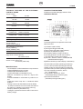
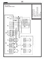
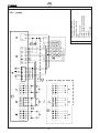
mase GENERATORS AUTOMATIC CONTROL PANEL MASE AT 92B I - LIBRETTO USO E MANUTENZIONE GB - USAGE AND MAINTENANCE MANUAL F - MANUEL D'INSTRUCTIONS ET D'ENTRETIEN D - HANDBUCHÜR BENUTZUNG UND WARTUNG E - MANUAL DE USO Y MANTENIMIENTO REV.5 MC. 04-05-07 cod.41235 GB AT 92B GENERATORS CONTENTS Foreword ..................................................................... 15 Suggestions for the installer ...................................... 15 Warranty ..................................................................... 15 Features of the electronic control board ................... 16 Mains feature .............................................................. 16 Construction features ................................................. 16 Wiring diagram ........................................................... 17 Technical term definition ............................................ 17 Measure display ......................................................... 18 Operating procedures ................................................ 19 Reset ........................................................................... 19 Manual ......................................................................... 19 Automatic .................................................................... 19 Test .............................................................................. 19 Automatic test............................................................. 19 Connecting/disconnecting automatic ........................ 19 Remote starting .......................................................... 19 Remote stop ............................................................... 20 Ejp function ................................................................. 20 Working hours calculation ......................................... 20 Periodic maintenance interval ................................... 20 Alarms and description codes .................................. 20 Parameters adjustable by the user (option) ............. 21 Troubleshooting .......................................................... 21 Colour legend .............................................................. 22 14 GB AT 92B GENERATORS FORE WORD - To protect from electric shocks and any atmospheric discharges, it is necessary to make a good grounding of all parts which can cause an earth return. The connection must be done using the yellow green cable sized in compliance with CEI 164.8 ART.9.6.01 AT92B and sets enable the control and the total running of a generating set with extremely easiness. Certain functions, which will be named as follows: 1 - OPTION parameters which can be adjusted by the user. 2 - SET UP parameters which can be adjusted by the installer enable modifications in the equipment functioning compared to standard version supply. OPTION parameters can be modified by the user himself, while SET UP parameters must be modified by skilled personnel, who are provided with all necessary information and knowledge in this field. We always suggest, however, that for further details and questions you consult skilled personnel. WARRANTY The control panel is fully guaranteed for one year after the date of purchase. The warranty is not valid if the fault is due to: A) faults in the installation and/or a use of the control panel not in compliance with the present technical and safety regulations; B) improper use of the control panel or in any case a use that is not in compliance with the manufacturers instructions; C) changes of the unit carried out without our previous approval; D) damages during transports; E) damages related to atmospheric discharges. In the above mentioned cases assistance , replacement of parts and transport are to be changed to customers. NOTICE These sets have been manufactured to avoid radiofrequency which could jam domestic or industrial equipment. ALWAYS SPECIFY THE SERIAL NUMBER WHEN ENQUIRING ABOUT YOUR CONTROL PANEL OR ASKING FOR WARRANTY SERVICE SUGGESTIONS FOR THE INSTALLER Customers must receive this set supplied with the present service manual which also includes warranty conditions. - All operations concerning the instal-lation of control panel should be carried out by skilled personnel in conformity with be performed when the control panel live, take the necessary precautions. - Electric connection must be carried out in compliance with the present CEI regulations. Particularly, supply cables must be size and placed so that the cable does not attain to temperatures which are 50-over room temperature. - It is necessary to check that no cables have loosened at the respective terminals and to remove any dust or other materials which have fouled the control panel during installation. The cleaning must be done by means of an exhausted, avoiding in any case blowing dust off the control panel with air. - Connections to the terminal board must be done using a cable of correct section, respecting carefully the electric diagram. - Never fix the control panel near heating sources or places where incidental electric leakages could cause an explosion. - This control panel standard version has a IP44 structure, for other uses ask for structures with adequate features. - To open the control panel front door use the proper tool supplied with the panel which should be placed so that only skilled personnel could reach it. 15 GB AT 92B GENERATORS TECHNICAL FEATURES OF THE ELECTRONIC CONTROL BOARD Supply voltage 12Vcc or 24Vc Operating field 9V-15V 18-30V Stand by input 100 mA 100 mA Battery charger voltage 13,8 Vcc CONSTRUCTION FEATURES AT92B control panel leakage protection: IP44 CARD DESCRIPTION 27,6 Charging current 500 mA Mains voltage control 0-220V+10% (380V on request) Generator voltage control 0-220V+10% (380V on request) Max. usable voltage Insulating voltage 400V 4 KVAC 1mm LEGEND The following devices are placed on the frontal side of the card: Max. usable current AT92B 16A per 380+N 30A per 220V single ph. Max. voltage on connections 15Vdc (V.Battery) 30Vdc (V.Battery 24V) Max. current 1) Led allarms (alarms ON) 2) Led engine ON (generator ON) 3) Led sf. failure (generator starting failure) 4) Led failures (fault/alarm signal) 5) Led battery (battery charger condition) 6) TLG led (generator remote control switch) 7) TLR led (main remote control switch) 8) Led VOLT, HERTZ, V.BATT, HOUR, METER (selected measure signal) 9) Measure buttons (to select display visualization) 10mA START/STOP ev./STOP magn./siren contact capacity 5A 125Vac 30Vdc Outlet contact capacity for remote control switch coils 5A 250Vac (380V max) 10) Test button (to select operating procedures) 11) Aut. button (to select operating procedures) 12) Man. button (to select operating procedures) 13) Reset button (to select operating procedures) 14) 3 figure display (measures, alarms, etc... visualizations) 15) Led RESET, MAN. AUT, TEST (selected operating procedure signal) 16) START/STOP buttons (Start/Stop of the generating set.) MAIN FEATURES - Control based on 11 Mhz Intel 80c552 microprocessors 32Kbyte EPROM memory program 32Kbyte static RAM data memory 256 word EPROM inviolate data memory Measure visualization by means of 3 figure, LED display Function/state/alarm visualization by means of 15 led Diaphragm button strip with 7 mechanical effect buttons Voltage measure at Real Effective Value (RMS) All setups accessible from the frontal side without dip switch (by software in permanent memory) Setups protected by admittance key Intelligent modulation of tension and current control battery charger 16 GB AT 92B GENERATORS 1 - Led allarms ON (allarms on): When on it indicates that the generator is being chacked and that all of the alarm signals are active. 2 - Led engine ON (generator on): When on it indicates that the generator has started. 3 - Led st. failure (generator starting condition): When on it indicates that, desplite attempts to start the generator, the generator has not started. 4 - Led failures (fault/alarm signal): When on it indicates generator stop for anomaly, read the alarm indentification message on the display. 5 - Led battery (battery charger condition): When on it indicates that the battery is ok. 6 - TLG led (generator remote control switch): When on it indicates that the panel has given closure consent to the group contactor. 7 - TLR led (mains remote control switch): When on it indicates that the panel has given closure consent to the mains contactor. 8 - Leds VOLT, HERTZ, V.BATT, HOUR, METER (selected measure signal): They switch on to indicate the selected measure. 9 - Measure button (to select display visualization): Press to select the measurement. 10 - Test button (to select operating procedures): Press to perform the test. 11 - Aut. button (to select operating procedures): Press for automatic functioning. 12 - Man. button (to select operating procedures): Press for manual operation. Warning! if stop is pressed in manual, the stoppage is not immediate: the cooling time must elapse before the stop, press RESET to stop immediately. Notice: If in manual mode, push for some seconds the manual button to switch from the network contactor to the unit contactor and viceversa. 13 - Reset button (to select operating procedures): Press to immediately stop the generator or to reset any alarms. 14 - 3 figure display (measures, alarms, etc... visualizat.): Communication display, in addition to the display of the following measurements genset and mains Volt, Hz, battery Volt, Hour counter, alarm messages appear, 15 - Leds RESET, MAN, AUT, TEST (selected operating procedure signal): They switch on to indicate the selected operating procedure. 16 - START/STOP buttons (Start/Stop of the generating set.): Press to START button the generating set is on, press to STOP button is stop (only in manual operation). By pushing it in the automatic mode, motor will be stopped immediately and the display will show the following message: E01, thus indicating that there is an emergency stop. Warning: If the STOP button is pressed in manual mode the motor cuts out after the cooling period. WIRING DIAGRAM LEGEND 1) Battery positive 2) Battery negative 3) Temperature 4) Oil 5) Remote stop (exchange mains and GE function EJP-SCR) 6) Remote starting (Start EJP-SCR) 7) Regulator yellow battery loading alternator type Saprisa 8) Regulator yellow battery loading alternator type Saprisa 9) Alternator D+ 10) Free 11) Neutral generator 12) Phase generator 13) Battery positive 14) Starting 15) Battery positive 16) Stop excitation, it is possible through a -17 set-up to change the operation of this outlet for an electro-magnet, an accelerator and a spark plug pre-heating 17) Stop de-energizing, it is possible through a -28 set-up to change the operation of this outlet for a solenoid valve and air starter control (or gasoline-fed motors 18)Horn 19) Alternator D+ 20) Battery positive 21) Neutral mains 22) Phase mains 29-30) TLR coil (NC contact) 31 -32) TLG coil (NO contact) 33-34) Generic alarm 35) Fuel optional 36) Free alarm (Only with optional 37) Free alarm cards installed) 38) Free 39) Free 40) Free J9 - N - RST Load outlet J8 - N - RST Generating set inlet J7 - N - RST Network Inlet Warning: It is of utmost importance lo install a fuse onto terminal 1 and a magnetothermal switch and/or differential onto inlets J8 and J7. 17 GB AT 92B GENERATORS TECHNICAL TERM DEFINITION generator frequency. The engine-ON signal is shown by its LED. Reading this manual you will meet with terms largely described below. Refer to the following definitions whenever these terms are mentioned in the manual: ALARMS ON Oil pressure and high temperature alarms are connected after a certain delay compared to the engineON signal. To stress that, the alarm-ON LED lights up. During the stopping cycle, the alarms are disconnected and simultaneously the fuel solenoid valve closes too. SET UP It is the stage of arrangement of the card which can be made before or during the installation of the card itself. All operating times and calculations which affect the system functioning can be set up and the parameters are stored on a permanent memory. This function can be reached by skilled personnel only and is protected by admittance key. ALARM OPERATING TIME Same procedure as in SET UP, but referred to parameters which can be adjusted also by the final user of the card. There is no admittance key. When one or more alarm signals occur, they immediately cause the generator remote control switch cutoff and accordingly the generator stopping, and ringing alarm. Becomes lower than the minimum fixed threshold and remains in that state for a while. That cause the mains remote control switch cutoff in any case. STARTING CYCLE MAINS ON Generator starting procedure, carried out through the following operations: first the fuel solenoid valve is activated. Then the control panel carries out some starting attempts (of adjustable duration) of the generator, alternating with intervals (of adjustable duration too). Once the engine is ON, the starting attempts stop immediately.If the engine fails to start after the fixed number of attempts, an acoustic alarm signal rings for 20 seconds lighting up the starting failure LED. To restore press RESET button. In the same way, the mains-ON signal occurs when, for a certain time, voltage exceeds the fixed threshold. The remote control switch make will depend on the selected operating procedure. OPTION GENERATOR ON Generator-ON signal works as the mains-ON signal described above. The delay interval is independent. On the contrary the generator is OFF when voltage becomes lower than the fixed threshold. MAINS/GENERATOR AND GENERATOR/MAINS SWITCHING STOPPING CYCLE Generator stopping procedure. The remote control switch opens and the engine continues to work for a certain time (cooling) at the end of which the fuel solenoid valve drops out and the stop magnet relay trips. The magnet remains energized till the generatorON signal stops and for a further time interval previously fixed. In case of emergency stop, the above mentioned procedure takes place without considering the cooling time. Between mains and generator remote control switches (besides the mechanical interlock) a delay time occurs to avoid their overlap . MEASURE DISPLAY The following measures can be selected on the display: - mains/generator voltage (Volt) - frequency of generator signal (Hertz) - battery voltage (V. Batt. ) - generator working hours (Hour Meter) The displayed measure is also signalled by the light up of its respective LED (TENS-FREQ-BATT-HOUR). To select another measure on the display press the measure button. When you select voltage measure and the generator is OFF, the display will show mains ENGINE ON The engine is ON when the 500 rpm signal, which comes out of the alternator, exceeds the fixed threshold or, if previously set during setup, when the generator voltage exceeds the starting threshold. As an emergency signal, working in parallel to one or the other signal, a threshold has been fixed on the 18 GB AT 92B GENERATORS voltage (starting LED OFF), but if the generator is ON the display will show generator voltage(starting LED ON). The displayed value of mains and generator voltage is precise at 1 volt, the frequency at 0.1 Hz, the battery voltage at 0.1 volt and working hour at one hour (even if the instrument measure is calculated in minutes). control switch is off. When the generator is running and its voltage reaches the fixed limits, the generator remote control switch makes. The generator goes on working till the mains is back. After the mains is back, the remote control switches exchange and the generator carries out the stopping cycle. When the generator is running it can be stopped by means of the stop button or the external stop signal. In automatic procedure both the external start connecting terminal and the automatic test are on too (see further) OPERATING PROCEDURES The card operates 4 different procedures, which are: - RESET - MANUAL - AUTOMATIC - TEST Each of these procedures is connected with a button and a signalling LED. To select a procedure push the respective button. It is also possible to change procedure at any time. Here follows a detailed description of each: TEST In TEST procedure the generator stars and the engine runs as long as you use this procedure, but the generator is loaded only when the mains drops. In that case the new exchange between remote control switches takes place only when changing from it is possible to stop the generator at once by pushing the stop button . AUTOMATIC TEST RESET When the card is in RESET, the generator stops if it was working and it will not be possible to carry out any operations. Selecting RESET procedure you will set to zero all displayed alarms, on condition that the alarms are not still effective (see alarms and failure messages). Also external controls are forbidden (external start, EJP function). The battery charger, however, is still working and you can select and see any measures on the display. AUTOMATIC TEST is a periodic check which is carried out by the control panel at fixed intervals (intervals can be fixed during set up) if the control panel is in automatic procedure and this very function had been previously set. After starting, the generotor runs for a fixed period at the end of which it stops. Before starting the warning horn rings signalling the beginning of this procedure. AUTOMATIC DISCONNECTION MANUAL In MANUAL procedure, the generator can be started or stopped by the respective START and STOP buttons. The START button is only used for beginning the starting cycle which, in any case, will be carried out automatically by the card, following the automatic starting procedure.STOP button, in the same way, begins the stopping cycle which will follow the automatic procedure (cooling, solenoid valve, magnet). The remote starting signal is forbidden. Alarrns work as usual (see ALARMS). In manual procedure, however, the automatic exchange between the remote control switches does not take place; the remote control switches work one by one. If you select manual procedure whenmains remote control switch is connected, it will be energized or de-energized with reference to the mains voltage, but the generator remote control switch will never be energized (the same remarks are valid if you select manual procedure when TLG is ON). TEST CONNECTION/ To connect or disconnect the automatic test function push MEASURE button and, while keeping it pressed, also push TEST button.The display will show the following messages: - OFF if the test is disconnected - ON.g if the test is connected (g stands for the number of interval days programmed during set Up) At this stage push START if you want to connect the function or STOP if you want to disconnect it. Pushing RESET you restore the normal operating procedure (while working on this function, in fact, the control panel maintains the previously selected procedure). Measure display goes back to voltage value. REMOTE STARTING When the card is in automatic procedure, the generator can be started be means of the remote starting connecting terminal. As in automatic test, the execution of the starting cycle is preceded by 5 seconds siren signal and 3 seconds interval. When the mains is back, however, the exchange does not take place till the engine has stopped (connecting terminal cutoff, failure, emergency stop). AUTOMATIC In AUTOMATIC procedure the generator starts when the mains voltage drops and its respective remote 19 GB AT 92B GENERATORS connected to the temperature connecting terminal. In this case the generator remote control switch opens and the generator stops at once. A02 OIL PRESSURE ALARM It operates like the one mentioned above, but it refers to the sensor for insufficient oil pressure. A03 500 RPM FAILURE ALARM This alarm appears when, during the generator running and with generator voltage on, the alternator signal (500 rpm) is missing. The generator stops. A04 GENERIC ALARM This alarm is connected when the engine-running signal depends only on the generator voltage. It occurs when, with engine on and without the intervention of stopping devices, the generator voltage is missing. Also in this case the emergency stopping cycle takes place. A05 REQUEST FOR MAINTENANCE This alarm occurs when the periodic maintenance interval, set up during the first setting or the last maintenance, has passed. The control panel, however, goes on working normally. A06 RUNAWAY SPEED ALARM This alarm occurs when frequency (therefore the engine revolution) exceeds the value fixed by SETUP. In this case the generator remote control switch opens and the generator stops immediately. EO1 EMERGENCY STOP This message is displayed when the generator is stopped by the operator by pushing the STOP button in automatic or test procedures. E03 REMOTE STOPPING ON It is displayed when the remote stopping connecting terminal is on. It stops the generator at once and forbids the generator starting. Unlike the other alarms, it resets automatically (without pushing RESET) when the connecting terminal contact opens. E04 GENERATOR VOLTAGE LACK It occurs when, with engine running, the generator voltage does not exceed the fixed threshold within a fixed time. REMOTE STOP The remote stop connecting terminal stops the generator at once in any operating procedures and forbids its starting. The display will show the relative code (E03). The connecting terminal cutoff will restore the control panel functioning automatically. EJP FUNCTION EJP function can be arranged during set up. When this function is ON the remote starting connecting terminal conform to EJP START and the stopping connecting terminal to EJP switching-consent. When the starting connecting terminal is ON a time delay occurs, at the end of which the starting cycle is carried out. Then, when the switching-consent signal arrives, the exchange between mains and generator takes place . At the switching-consent cutoff, the load returns on the mains and the generator carries out the stopping cycle at the starting connecting terminal cutoff. EJP function is connected only in automatic procedure. Protections and alarms are on too. WORKING HOUR CALCULATION After the engine starting, the working minutes are counted. The calculation, expressed in hours, can be shown on the display. The calculation continues even in case of disconzero by the user. Switching off the connecting terminal, the stopping cycle is carried out. While working the generator by this function, if the mains drops the load moves to the generator. PERIODIC MAINTENANCE INTERVAL By means of SET UP, a periodic maintenance interval, expressed in hours, is set. When the working minutes reach the fixed amount, the display shows the code of maintenance request. The control panel, however, goes on working normally. Pushing RESET you set to zero the calculation and the message disappears. ERRORS/ALARMS SUMMARY ERR DESCRIPTION A01 Temperature alarm A02 Oil pressure alarm A03 5OO RPM failure alarm A04 Oil sensor alarm A05 Request for maintenance A06 Runaway speed alarm E01 Emergency stop E03 Remote stopping on E04 Generator voltage lack ALARM AND DESCRIPTION CODES The display can show certain codes to signal emergency or specific situations. The message disappears only when those emergency conditions have disappeared too and the user has pressed RESET button. Here follows the scheduled codes: A01 TEMPERATURE ALARM This message appears when, with the engine running and alarms on, there is an intervention of the sensor 20 GB AT 92B GENERATORS MESSAGES TABLE CODE MEANING STA START STO A.TE E.ST STOP Code DISPLAY CONDITION During the start-up cycle of the generating set During the stopping of the generating set after the cooling time AUTOMATIC TEST During the automatic test cycle REMOTE STARTING With remote starting signal EJP EJP FUNCTION When the EJP start entry is active and the system is in automatic mode SCR SCR FUNCTION When the SCR start entry is active and the system is in automatic mode PARAMETERS WHICH CAN BE ADJUSTED BY THE USER (OPTION) To reach the parameters which can be adjusted by the user position in RESET, then push RESET and contemporary push MEASURE for 5 seconds. The display will show the code of the first value to be set (OP.1) At this stage , using MEASURE button , you can select the parameter that you want to modify. By pushing START or STOP button you will see the established value of the parameter on the display for 3 seconds. During that interval if you push again the START button you can increase the variable (up to its max. granted limit), while by pushing the STOP button you can decrease it (up to its min. limit). If you do not push any button and let the 3 seconds pass, you go back to option selection (OP.X). By pushing RESET you can leave this procedure. If you do not push any buttons for 30 seconds, the control panel leaves this procedure automatically. Here follows a table of the adjustable options with the minimum and maximum allowed values for each. Option Range Default OP. 1 Mains voltage minimum threshold 160-230 VAC 190 VAC OP. 2 Mains voltage maximum threshold 253-345 VAC 253 VAC OP. 3 Mains off delay 0 - 120 sec 5 sec OP. 4 Mains on delay 0 - 240 sec 10 sec OP. 5 Generator voltage minimum threshold 160-230 VAC 190 VAC OP. 6 Generator voltage maximum threshold 253-345 VAC 253 VAC OP. 7 Generator off delay 1 - 180 sec 5 sec OP. 8 Generator on delay 1 - 180 sec 20 sec OP. 9 Cooling time 1 - 300 sec 30 sec OP. 10 Alarm ringing time 0 - 60 sec 20 sec OP. 11 Automativc test time interval 1 - 7 gg 3 gg OP. 12 Automatic test duration 1 - 30 min OP. 13 Engine start delay after EJP start 0 - 99 min 25 min Commutation delay for EJP/T (1wire) 0 - 30 min 5 min OP. 14 10 min TROUBLESHOOTING 1) Three dotted lines appear on the display screen both when the machine is switched on and during start-up. - battery voltage is too low - check that power cables are tightened in their clamps - replace battery or recharge it NOTICE: - Options number 13 and 14 are displayed only if EJP function has been activated during setup. - The values quoted under default are set during the card setup. 2) During start-up the card is reset and switches off and then switches on again all leds. - battery voltage is too low - check that power cables are tightened in their clamps - replace battery or recharge it 3) Unit’s remote switch does not switch on (in automatic mode). TLG LED is ON. - check fuse (in versions with fuse) - use appropriate instrument to check that reel is correct - if the TLG led is off, check that minimum and maximum voltage values (codes P.O5-P.06) have been set correctly on the basis of the value read on the unit voltage display. Use the option function to adjust. 21 GB AT 92B GENERATORS 4) Networks remote switch does not switch on (in automatic mode). TLR LED is ON. COLOUR LEGEND "FX" 1 01 02 11 12 14 16 - check fuse (in versions with fuse) - use appropriate instrument to check that reel is correct - if the TLR led is off, check that minimum and maximum voltage values (codes P.01-P.02) have been set correctly on the basis of the value read on the unit voltage display. Use the option function to adjust. N.B. For versions with separate DRV minimum and maximum voltage relay check that the adjustments are correct in relation to the actual network voltage value. When this Leds green light is on, the calibration is correct. &2/285 PINK GREEN GREY WHITE BROWN YELLOW B R IGGS & S T R AT T ON / S UZ UK I 3523(57< POSITIVE - BATTERY NEGATIVE - BATTERY NEUTRAL - GENERATOR 220V PHASE - GENERATOR 220V START STOP (EXCITATION) COLOUR LEGEND "FX" HONDA - "SILENT 5000B" Robin 5) Voltage and frequencies recordings on the display are unstable. - card probably set at incorrect frequency - Set-up -01 has been incorrectly set in relation to frequency used. Change setting by using set-up (only for specialised personnel following set-up procedure). 1 01 02 03 04 07 08 11 12 14 16 17 &2/285 1 01 02 03 04 07 08 11 12 14 16 17 &2/285 RED BLACK GREEN GREY BROWN WHITE 0.5 Ø GREY 1.5 Ø BLUE 1.5 Ø YELLOW PINK VIOLET 3523(57< POSITIVE - BATTERY NEGATIVE - BATTERY ENGINE TEMPERATURE LOW OIL PRESSURE BATTERY CHARGER REGULATOR BATTERY CHARGER REGULATOR NEUTRAL - GENERATOR 220V PHASE - GENERATOR 220V START STOP (DE-EXCITATION) AUTOMATIC AIR STARTER COLOUR LEGEND "PD" YANMAR 6) During start-up the card reports that the motor is running even if the motor has not started up. - double motor running signal reaches the card - for motors without battery charging alternator (D+) and with monitoring by clamps 7 and 8 remove wire 9 from terminal block J5 of the card - set motor running threshold according to type of measurement selected start set-up and check setting of parameters: set-up: -05, -06, -07 (only for specialised personnel following procedure). 7) Excessive motor speed alarm A06 message appears although the motor is running correctly. - the problem is caused by a very rapid signal peak on voltage wave of alternator voltage during start-up - contact alternator supplier in case you need filters. - override safety device by means of function -34 of set-up (only for specialised personnel following procedure). 22 RED BLACK GREEN GREY BROWN WHITE 0.5 Ø BLUE 1.5 Ø BLUE 1.5 Ø YELLOW PINK 3523(57< POSITIVE - BATTERY NEGATIVE - BATTERY ENGINE TEMPERATURE LOW OIL PRESSURE BATTERY CHARGER REGULATOR BATTERY CHARGER REGULATOR NEUTRAL - GENERATOR 220V PHASE - GENERATOR 220V START STOP (DE-EXCITATION) 2 3 1 4 6 7 1 2 3 4 5 6 7 A B C Electronic printed circuit Three phases connection Single phase connection Alarm Genset connector Auxiliary contact remote START Auxiliary contact remote STOP To users To genset To mains supply GB GENERATORS AT 92B "FX" BRIGGS & STRATTON / SUZUKI 23 1 2 3 4 5 6 7 A B C "FX" HONDA "SILENT 5000B" Robin Electronic printed circuit Three phases connection Single phase connection Alarm Genset connector Auxiliary contact remote START Auxiliary contact remote STOP To users To genset To mains supply GB GENERATORS AT 92B 24 1 2 3 4 5 6 7 A B C Electronic printed circuit Three phases connection Single phase connection Alarm Genset connector Auxiliary contact remote START Auxiliary contact remote STOP To users To genset To mains supply GB GENERATORS AT 92B "PD" YANMAR 25