1
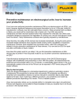
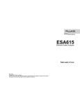
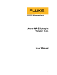
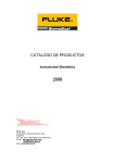
Preventive maintenance on
electrosurgical units: How to
increase productivity using
test automation software
White Paper
Figure 1: The QA-ES Electrosurgery
Analyzer hooked up to The Switch Box
and an Electrosurgery unit.
If you’ve ever performed preventive maintenance
(PM) on an electrosurgical unit (ESU), you know it
requires proper expertise and specialized information to do so. In the past, opting for a manufacturer
contract alleviated concerns surrounding ESU
preventive maintenance.
When a problem or failure occurred, users
would call for technical repair and/or request a
loaner unit. ESUs were sent for maintenance and
later returned repaired and/or fully inspected for a
flat-rate cost. Because ESUs were considered dangerous equipment, only the manufacturer would
touch the device, regardless of contract cost.
In recent years, ESU safety has substantially
increased. Most hospitals have newer, safer ESU
units and in-house preventive maintenance
programs. Increased budget restrictions have
required careful scrutiny and/or cancellation of
expensive maintenance contracts. ESUs are now
sent for repair only after a fault or defect has been
confirmed.
Designed with these practices in mind, Fluke
Biomedical developed the Ansur-automated
version of the QA-ES Electrosurgical Analyzer to
help increase productivity, safety and eliminate
down time. With this system, all measurements
are performed and documented within 12 to 15
minutes. A customizable report is automatically
created at the end of the PM and can be exported
in PDF format using any PDF software.
Additionally, Fluke Biomedical developed The
Switch Box and Return Electrode Current Monitoring (RECM) Test Box (Figure 1) that works with
Ansur to leverage the internal “footswitch” capability of the QA-ES.
• The Switch Box allows a differentiation
between cut and coagulation commands. The
two modes can be selected using a switch
instead of changing the wiring for each mode.
• RECM Test Box is intended to test the Return
Electrode Current Monitoring alarm.
Step-by-step ESU test guide using the
QA-ES Ansur Plug-In Software
There are several reasons why a biomedical
department should adopt an Ansur automated
test solution. For starters, Ansur test automation
allows users to precisely define each step in the
PM process using a pre-made template. Pictures
and diagrams can be added to these templates
to provide a visual guide, as shown in Figure 2.
Specific service manual information can also be
added to the Ansur template, making bulky print
manuals an item of the past.
Additionally, each template can be customized to reflect the exact model to which it refers
and those model-specific inspection and testing
steps required by the ESU manufacturer. Because
Ansur templates are stored in a PC, there is no
limit to the number of PM procedures that can be
automated.
Automated procedures allow technicians
with minimal training to successfully perform
a PM with ease. Users are guided step-by-step
through the test, while the software minimizes
risk of human error. This occurs by automatically
configuring the QA-ES for the specific test, and
collecting pre-defined values to determine pass or
fail outcome. Pass or fail outcomes are displayed
in Figure 3.
Figure 2: Step-by-step checklist for monopolar output test.
Figure 3: The Ansur test automation software shows clear pass or fail test outcomes.
2
Fluke Biomedical
Preventive maintenance on electrosurgical units: How to increase productivity using test automation software
Figure 4: Custom limits for power, current, voltage peak-to-peak, and crest factor.
Additional columns such as “Not Applicable”
can also be included to accommodate special
circumstances, such as a missing accessory. The
automation software automatically collects the test
measurements and verifies they are within the
specified limits.
Custom limits can be set for power, current,
voltage peak-to-peak, or crest factor. In Figure 4,
the limits are set for current. For power, limits can
be set in percentage of the nominal power or in
absolute values (watts).
If the QA-ES internal footswitch is used, the
operator does not need to press the ESU footswitch. The QA-ES closes a relay when needed,
which causes the high frequency (HF) signal to
alarm and stops the generator while collecting
results. With one single click, the measurement is
performed, collected, and documented.
Testing the REM/ARM function
A decade box is recommended to verify accurate
REM/ARM function.
The RECM test box (Decade Resistance Box)
tests the Return Electrode Current Monitoring
alarm. Simply choose the cable that fits your ESU
neutral plate connector and select the appropriate
resistance value as instructed in the ESU manufacturer’s RECM test procedure (incorporated into
the Ansur ESU test template).
As shown in Figure 6, Ansur test automation
easily guides the user in verifying REM/ARM
alarm function.
User-friendly navigation
Easy-to-use navigation allows users to verify
proper settings and secure work. Simply select
NEXT to proceed to the next step. Or, select PREVIOUS to go back to verify the proper mode has been
set on the ESU (Figure 5). If a change is made, the
new measurement will overwrite the previous
erroneous one and, this time, the test will pass
without having to restart the entire procedure
from the beginning.
Figure 5: Toolbar buttons.
Figure 6: Verifying REM function.
3
Fluke Biomedical
Preventive maintenance on electrosurgical units: How to increase productivity using test automation software
Power distribution curve
Occasionally it’s necessary to perform a concentrated analysis of ESU performance. Newer
Electrosurgery units asses the presented impedance to the active electrode and automatically
adjust the output voltage or current. This process
improves coagulation. However, older generators may require manual ESU output adjustments
during surgery.
The power distribution test applies the selected
output energy through a series of test loads
representing the variety of impedances presented in Figure 7, and displays the measured
output energy. The power distribution curve will
show whether the energy selected is the energy
delivered.
A power distribution curve also illustrates if the
power output is effectively generated, as expected
over an extended patient load selection. This data
is required by standards ANSI/AAMI/IEC 606012-2: 2006 in loads ranging from 100 Ω to 2000 Ω
for all monopolar modes. Once the test template is
created, the Ansur test automation automatically
captures a power distribution curve in approximately 20 seconds.
There are 128 load selections in the QA-ES
starting at 10 Ω, then from 25 Ω to 2500 Ω
increasing in 25 Ω increments and 2500 Ω to
5200 Ω increasing in 100 Ω increments. Testing at
such high impedance loads may seem unnecessary, but doing so simulates real-life conditions.
For example, when an organ is protected by
a glucose solution, the resistance becomes very
high. Therefore, testing at high impedance loads
is not only necessary, but critical. Loads can be
tested in increasing or decreasing order.
Figure 7: Power distribution curve.
Power output vs. setting
The ANSI/AAMI/IEC 60601-2-2: 2006 standard
also requires the power output to be shown versus
the output control setting at a specified load. This
is usually the nominal value for which the power
reaches its maximum (Figure 8).
Power output testing is a requirement in the
manufacturer’s preventive maintenance protocols,
and can easily be achieved using QA-ES test
automation. Because this test requires ESU power
setting adjustments for each step, it takes longer
than a power distribution test. However, using the
QA-ES internal footswitch to control the ESU is
still very convenient.
4
Fluke Biomedical
Figure 8: Power output graph.
Preventive maintenance on electrosurgical units: How to increase productivity using test automation software
Measuring high frequency
leakage current
Measuring high-frequency (HF) leakage current is
a standard in most test procedures. This can also
be performed with the Ansur-automated QA-ES
software. The ability to upload diagrams and
customized instructions allows test visualization
and minimal dependence on training resources.
The limits are easily set to match the ESU specifications and testing procedure (Figure 9).
For monopolar outputs, 100 mA is recommended,
otherwise use the special table described in the
standard. A lower limit is applicable for bipolar
outputs (usually 50 mA to 70 mA) but the standard
sets a formula based on the maximum power for a
given bipolar mode. However, it should not exceed
one percent of the nominal power converted into
current through the measurement resistor (load).
This formula is included in the QA-ES Ansur automation software.
According to the standard, HF leakage currents
are measured using a 200 Ω load. When testing
an ESU with HF grounded neutral plate, a second
200 Ω load is needed. This additional load is
integrated into the QA-ES. Measurement order is
strategically optimized to reduce mid-test wire
changing, resulting in increased productivity.
Instructions are shown in large characters on
the PC during the tests to simply illustrate which
electrode, mode, and power settings to use. A
similar screen appears when measuring a power
distribution curve or a power output
Measuring low frequency
leakage current
Protocols for testing low frequency (LF) current
vary depending on the make and model of the ESU
device. The following electrical safety analyzers
include an automatic electrical safety test in the
protocol:
• Fluke Biomedical ESA615
• Fluke Biomedical ESA620
• Fluke Biomedical ESA612
Automatic electrical safety test protocol allows
user to obtain one single model-specific test result
file and report per ESU, including:
• Visual inspection
• REM/ARM function test
• Performance analysis
• HF leakage current
• Low frequency leakage current
5
Fluke Biomedical
Figure 9: High frequency leakage current.
After creation, the document can be linked to the
user’s CMMS/database system. By beginning a
work assignment created in the CMMS/database,
the Ansur-created ESU test template is automatically launched. The DUT information populates the
appropriate fields in the template, and the initial
automated test guide is displayed with instructions for how to proceed.
After the test is performed, the software automatically creates a link between the results and
the CMMS/database. The overall test status (Pass/
Fail) can be viewed on the CMMS/database and
used to automatically close the original work
assignment (assuming the overall test result was
Pass).
Likewise, an overall test status of Fail could
trigger the CMMS/database to extract the failed
test results from the Ansur test result file. It would
then use that information to automatically open
a new work assignment and populate the workassignment fields for “problem reported.”
Preventive maintenance on electrosurgical units: How to increase productivity using test automation software
Peak-to-peak voltage output
When using a current transformer, the RF signal
is converted into a low voltage in order to be
measured. This voltage is an image of the current,
not the HF output voltage generated by the ESU.
The QA-ES measures the peak-to-peak voltage directly. This measurement is useful when
troubleshooting an ESU, as some ESUs require
a voltage measurement at low frequency, which
cannot be accomplished using a current transformer. Such coils have a low-end frequency
response at about 40 kHz. The QA-ES can handle
this measurement.
Summary
The Ansur QA-ES plug-in, supported on the Ansur
software, provides remote access to all functionality of the QA-ES Electrical Electrosurgical
Analyzer. A unique Ansur QA-ES test element is
available for each of the QA-ES Electrical Electrosurgical Analyzer measurements.
The Ansur-automated QA-ES software streamlines ESU preventive maintenance and allows
users to increase productivity with the following
functions:
• Step-by-step test templates including pictures,
diagrams, and hyperlinks
• User-friendly Ansur test automation
functionalities including:
– Checklists and user messages
– Output power, current, peak-to-peak voltage,
and crest factor measurements
– Low frequency leakage currents included
when using an automation compatible with
Fluke Biomedical electrical safety analyzers
– Measurements are automatically captured
and compared to the specified limits to
reduce human error
– Automatically generated comprehensive
reports
About the QA-ES Electrosurgery
Analyzer
The QA-ES Electrosurgery Analyzer is the ESU
tester you can depend on for complete preventive
maintenance and ESU safety testing to test all
critical functions.
To learn more about the QA-ES Electrosurgery
unit, Ansur test automation software, or any other
medical test equipment mentioned in this document, click here or visit flukebiomedical.com.
Fluke Biomedical.
Better products. More choices. One company.
Fluke Biomedical
6045 Cochran Road
Cleveland, OH 44139-3303 U.S.A.
For more information, contact us at:
(800) 850-4608 or Fax (440) 349-2307
Email: [email protected]
Web access: www.flukebiomedical.com
©2013 Fluke Biomedical. Specifications subject to change
without notice. Printed in U.S.A.
11/2013 6001337A_EN
Modification of this document is not permitted
without written permission from Fluke Corporation.
6
Fluke Biomedical
Preventive maintenance on electrosurgical units: How to increase productivity using test automation software