1
A5x-02 Ascent Trainer
SER V ICE M A N U A l
table of contents
CHAPTER 1: Serial number location . ......................................................... 1
CHAPTER 2: Important Safety instructions
2.1
2.2
2.3
Moving the Unit........................................................................................................... 3
Read and Save These Instructions............................................................................. 4
Electrical Requirements ............................................................................................. 5
CHAPTER 3: Preventative Maintenance
3.1
3.2
3.3
3.4
Recommended Cleaning Tips . ..................................................................................
Check for Damaged Parts .........................................................................................
Care and Maintenance Instructions ...........................................................................
Preventative Maintenance Checklist . ........................................................................
6
6
7
7
CHAPTER 4: CONSOLE overlay and workout description
4.1
4.2
4.3
4.4
4.5
4.6
4.7
4.8
Console Description ...................................................................................................
Workout Setup Steps - Manual...................................................................................
Workout Setup Steps - Fat Burn.................................................................................
Workout Setup Steps - Level Based...........................................................................
Workout Setup Steps - Fitness Test............................................................................
Workout Setup Steps - Target Heart Rate..................................................................
Workout Setup Steps - Constant Watts......................................................................
Auto Calibration Instructions.......................................................................................
8
9
9
9
10
11
11
12
CHAPTER 5: Manager MODE
5.1
5.2
Using Manager Mode ................................................................................................ 13
Manager Mode Overview............................................................................................ 14
CHAPTER 6: ENGINEERING / Service MODEs
7.1
Using Engineering / Service Mode ............................................................................ 15
CHAPTER 7: Troubleshooting
7.1
7.2
7.3
7.4
Electrical Diagram ......................................................................................................
LCB Error Indicators ..................................................................................................
Console Error Codes..................................................................................................
Troubleshooting...........................................................................................................
16
19
20
21
CHAPTER 8: PART REPLACEMENT GUIDE
8.1
8.2
8.3
8.4
8.5
8.6
8.7
8.8
Front Disk Replacement ............................................................................................
Front Shroud Removal................................................................................................
Lower Control Board (LCB) Replacement..................................................................
ECB (Electromagnetic Brake) Replacement...............................................................
ECB Belt Replacement...............................................................................................
Drive Belt Replacement..............................................................................................
Pulley Axle Set Replacement......................................................................................
Drive Axle Set Replacement.......................................................................................
22
25
26
27
29
30
31
32
table of contents
8.9
8.10
8.11
8.12
8.13
8.14
8.15
8.16
8.17
8.18
8.19
8.20
Console Replacement.................................................................................................
Overlay & Keypad Replacement.................................................................................
Handlebar Assembly Replacement.............................................................................
Rear Shroud Replacement.........................................................................................
Incline Motor Replacement.........................................................................................
Dual Action Handlebar Replacement..........................................................................
Foot Pedals Replacement...........................................................................................
Pedal Arm Replacement.............................................................................................
Link Arm Replacement................................................................................................
Swing Arm Replacement.............................................................................................
Rear Pivot Arm Replacement......................................................................................
Testing the Ascent Trainer...........................................................................................
33
34
37
38
39
41
42
43
44
46
48
49
CHAPTER 9: EXPLODED DIAGRAMS
9.1
9.2
9.3 9.4
Ascent Trainer Specifications ....................................................................................
Fasteners & Assembly Tools.......................................................................................
Ascent Trainer Assembly Steps .................................................................................
Stabilizing the Ascent Trainer......................................................................................
50
51
52
56
CHAPTER 10: UPGRADES
iv
10.1
10.2
10.3
10.4 Belt Tensioner Bearing Replacement..........................................................................
Bearing Assembly Shimming .............................................................................. ......
Upgrading Hand grips with Resistance Buttons ..................................................... ..
Installing Adjustable Tensioner....................................................................................
57
58
59
60
CHAPTER 11: SOFTWARE UPGRADE PROCEDURE
11.1
Software Upgrade Procedure..................................................................................... 64
Chapter 1: serial number location
1.1 SERIAL NUMBER LOCATION
SERIAL Number Placement
1
Chapter 1: Serial number location
1.1 SERIAL NUMBER LOCATION - CONTINUED
console serial number location
2
Chapter 2: important safety instructions
2.1 Moving the Unit
Two hand holds are located just above the MATRIX logo on the rear
legs.
The A5x-02 Ascent Trainer weighs 395 lbs. To avoid injury to the
user and the unit, be sure to have proper assistance to move the
unit.
3
Chapter 2: important safety instructions
2.2 REad and Save These Instructions
This Ascent Trainer is intended for commercial use. To ensure
your safety and protect the equipment, read all instructions before
operating the MATRIX Ascent Trainer.
CAUTION! If you experience chest pains, nausea, dizziness, or
shortness of breath, stop exercising immediately and consult
your physician before continuing. When using an electrical product, basic precautions should always be
followed including the following:
CAUTION! Any changes or modifications to this equipment
could void the product warranty. • A
n appliance should never be left unattended when plugged
in. Unplug the unit from the outlet when not in use and before
putting on or taking off any parts.
• T
his product must be used for its intended purpose
described in this service manual. Do not use other
attachments that are not recommend by the manufacturer.
Attachments may cause injury.
• T
o prevent electrical shock, never drop or insert any object
into any opening. • D
o not remove the console covers. Service should only be
done by an authorized service technician.
• N
ever operate the Ascent Trainer with the air opening
blocked. Keep the air opening clean, free of lint and hair.
• Do not carry this unit by it’s supply cord or use the cord as
a handle. • C
lose supervision is necessary when the Ascent Trainer is
used by or near children or disable persons.
• Do not use outdoors. • D
o not operate where aerosol (spray) products are being
used or when oxygen is being administered.
• T
o disconnect, turn all controls to the off position, then
remove the plug from the outlet.
• Connect this Ascent Trainer to a properly grounded outlet
only.
• D
o not use the equipment in any way other than designed or
intended by the manufacturer. It is imperative that all Matrix
Fitness Systems equipment is used properly to avoid injury.
• Keep hands and feet clear of moving parts at all times to
avoid injury.
• Unsupervised children must be kept away from this equipment.
• Do not wear loose clothing while on the equipment.
4
Chapter 2: important safety instructions
2.3 Electrical Requirements
For your safety and Ascent Trainer performance, the ground on this
circuit must be non-looped. Please refer to NEC article 210-21 and 21023. Your Ascent Trainer is provided with a power cord with a plug listed
below and requires the listed outlet. Any alterations of this power cord
could void all warranties for this product. Multiple Ascent Trainers can
be powered on one dedicated circuit. (3 units per 15 Amp and 4 units
per 20 Amp dedicated circuit.)
GROUNDING INSTRUCTIONS:
The Matrix Ascent Trainer must be grounded. If it should
malfunction or break down, grounding provides a path of least
resistance for electric current to reduce the risk of electric shock.
The Ascent Trainer is equipped with a cord having an equipment
grounding conductor and a grounding plug. The plug must be
plugged into an appropriate outlet that is properly installed and
grounded in accordance with all local codes and ordinances. If the
user does not follow these grounding instructions, the user could
void the Matrix limited warranty.
DANGER: Improper connection of the equipment grounding
conductor can result in the risk of electric shock. Check with a
qualified electrician if the user is in doubt as to whether the product
is properly grounded. Do not modify the plug provided with the
product if it will not fit the outlet, have a proper outlet installed by an
electrician
MATRIX DEDICATED CIRCUIT/ELECTRICAL REQUIREMENT INFO
All Matrix Ascent Trainers require the use of a 15 amp or 20 amp
“dedicated circuit,” with a non-looped (isolated) neutral/ground, for the
power requirement. Quite simply this means that each outlet you plug
Ascent Trainers into should not have anything else running on that
same circuit besides other Ascent or Incline Trainers (up to 3 per 15
amp circuit and 4 per 20 amp circuit). The easiest way to verify this is to
locate the main circuit breaker box, and turn off the breaker(s) one at a
time. Once a breaker has been turned off, the only thing that should not
have power to it are the Ascent/Incline Trainers in question. No lamps,
vending machines, fans, sound systems, or any other item should lose
power when you perform this test.
Non-looped (isolated) neutral/grounding means that each circuit must
have an individual neutral/ground connection coming from it, and
terminating at an approved earth ground. You cannot “jumper” a single
neutral/ground from one circuit to the next.
In addition to the dedicated circuit requirement, the proper gauge wire
must be used from the circuit breaker box, to each outlet that will have
the maximum number of units running off of it. If the distance from
the circuit breaker box, to each outlet, is 100 ft or less, then 12 gauge
wire may be used. For any distance greater than 100 ft from the circuit
breaker box to the outlet, 10 gauge wire must be used.
5
Chapter 3: Preventative maintenance
3.1 RECOMMENDED CLEANING TIPS
Preventative maintenance and daily cleaning will prolong the life and
look of your MATRIX Ascent Trainer.
Please read and follow these tips.
• P
osition the equipment away from direct sunlight. The intense UV
light can cause discoloration on plastics.
• L
ocate your equipment in an area with cool temperatures and low
humidity.
• Clean with a soft 100% cotton cloth.
• C
lean with soap and water or other non-ammonia based all purpose cleaners.
• W
ipe foot pads, handles, heart rate grips, and handlebars clean
after each use.
• D
o not pour liquids directly onto your equipment. This can cause
damage to the equipment and in some cases electrocution.
• Check pedal motion and stability.
• Adjust leveling feet when equipment wobbles or rocks.
• Maintain a clean area around equipment, free from dust and dirt.
6
3.2 check for damaged parts
DO NOT use any equipment that is damaged or has worn or broken
parts. Use only replacement parts supplied by Matrix Fitness
Systems.
maintain labels and nameplates. Do not remove labels
for any reason. They contain important information. If unreadable or
missing, contact Matrix Fitness Systems for a replacement. 1-866693-4863, www.matrixfitness.com
maintain all equipment Preventative maintenance is the key
to smooth operating equipment. Equipment needs to be inspected
at regular intervals. Defective components must be replaced
immediately. Improperly working equipment must be kept out of use
until it is repaired. Ensure that any person(s) making adjustments
or performing maintenance or repair of any kind is qualified to do
so. Matrix Fitness Systems will provide service and maintenance
training at our corporate facility upon request or in the field if proper
arrangements are made.
Chapter 3: Preventative Maintenance
3.3 CARE AND MAINTENANCE INSTRUCTION
In order to maximize life span, and minimize down time, all MATRIX
equipment requires regular cleaning, and maintenance items performed
on a scheduled basis. This section contains detailed instructions on how
to perform these items, the frequency of which they should be done, and a
check list to sign off each time service is completed for a specific machine.
Some basic tools and supplies will be necessary to perform these tasks
which include (but may not be limited to):
* Metric Allen wrenches
* #2 Phillips head screwdriver
* Adjustable wrench
* Torque wrench (capability to read foot lbs, and inch lbs)
* Lint free cleaning cloths
* Teflon based spray lubricant
* Mild, water soluble, detergent – such as “Simple Green”, or other Matrix
approved product
* Teflon based spray lubricant such as “Super Lube”, or other Matrix
approved product
* Vacuum cleaner with an extendable hose and crevasse tool attachment
Please find the worksheet sample for our equipment provided in this
manual and make copies as needed. Keep them up to date as the required
service / maintenance items are performed. It is critical that you also log the
accumulated (total) amount of miles or running hours on the equipment each
time service or maintenance is performed.
You may periodically see addendums to this document, as the Matrix
Technical Support Team identifies items that require specific attention,
the latest version will always be available on the Matrix website, www.
matrixfitness.com
3.4 preventative maintenance checklist
Make:
Model:
Location:
Technician:
S/N
DATE:
Inspect power cords
Check resistance system
Check E-stop cord/button
Lubricate pivot points
Clean/lube guide rods
Vacuum/clean under cover
Check connecting joints
Inspect belt/cable assy.
Check motor drive belt
Remove covers, check
belts
Check locking pins
Check running belt
Flip/replace deck
Check pulleys
Check pedal & crank
Inspect upholstery
De-wax rollers
Check/lube seat
adjustment
Notes/comments
Verify electronics operation
Make:
Model:
Location:
Technician:
Check/tighten hardware
Lubricate Acme screw
S/N
DATE:
DAILY MAINTENANCE ITEMS
1)
Clean the entire machine using water and mild detergent such as
“Simple Green”, or other Matrix approved solutions (cleaning agents
should be alcohol and ammonia free).
QUARTERLY MAINTENANCE ITEMS
1)
Check all connecting joint areas for tightness of bolt assemblies.
2)
Ensure that there is little, or no free play at all joint assemblies once
bolts have been tightened. Installation of washer kits may be required
if free play does not come out from tightening bolts.
3)
4)
Remove plastic covers, and lubricate the ball joint where the Link Arm
and Handlebar join together. A grease gun, with a needle fitting adapter
is required for this (Matrix recommends using Superlube brand grease
with PTFE {Teflon} additive).
Inspect power cords
Check resistance system
Check E-stop cord/button
Lubricate pivot points
Clean/lube guide rods
Vacuum/clean under cover
Check connecting joints
Inspect belt/cable assy.
Check motor drive belt
Remove covers, check
belts
Check locking pins
Check running belt
Flip/replace deck
Check pedal & crank
De-wax rollers
Check/lube seat
adjustment
Notes/comments
Verify electronics operation
Check pulleys
Inspect upholstery
Check/tighten hardware
Lubricate Acme screw
Remove plastic covers, and lubricate the Acme screw on the left and
right incline motors (Matrix recommends using Superlube brand grease
with PTFE {Teflon} additive).
7
Chapter 4: Console overlay and workout description
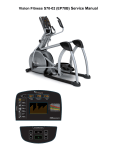
4.1 CONSOLE DESCRIPTION
WORKOUT KEYS Simple program view and selection buttons.
GO: One touch Start.
ENTER: To confirm each program setting.
UP / DOWN INCLINE: Easy information and incline selection.
UP / DOWN LEVEL: Easy information and level selection.
UP / DOWN TIME: Easy information and time adjustment.
STOP: Ends workout and shows workout summary data.
NUMBER KEYPAD: Workout data input for workout setup. Level adjustment during workout.
COOL DOWN: Puts the Ascent Trainer into Cool Down Mode.
FAN: Allows for fan speed selection (fan has 3 operating speeds).
8
Chapter 4: Console overlay and workout description
4.2 workout setup steps - MANUAL
GO - Press to immediately begin a workout. Workout, resistance
level, and time will automatically go to default settings. Pressing
GO will not prompt user for age, weight, or level settings.
1) Start pedaling and press the GO key to begin your workout. 2)
The display will read 3, 2, 1, Begin and then the program will start.
MANUAL - Manual allows the user to input more information
while defining their own workout. Calorie expenditure will be more
accurate when inputting information in Manual than by pressing GO.
1) Start pedaling, press the MANUAL key.
2) Select Level by using the UP or DOWN LEVEL keys and press
ENTER.
3) Select Time by using the UP or DOWN LEVEL keys and press
ENTER.
4) Select Weight by using the UP or DOWN LEVEL keys and press
ENTER.
5) The display will read 3, 2, 1, Begin and then the program will
start.
4.3 workout setup steps - fat burn
FAT BURN - Fat burn is a level based program that is designed
to help users burn fat through various resistance level changes.
1) Start pedaling and press the FAT BURN key.
2) Select Level by using the UP or DOWN LEVEL keys and press
ENTER.
3) Select Time by using the UP or DOWN LEVEL keys and press
ENTER.
4) Select Weight by using the UP or DOWN LEVEL keys and press
ENTER.
5) The display will read 3, 2, 1, Begin and then the program will
start.
4.4 workout setup steps - LEVEL BASED
ROLLING HILLS - The Rolling Hills program is a level based program
that automatically adjusts the resistance level to simulate real terrain.
1) Start pedaling and press the ROLLING HILLS key.
2) Select Level by using the UP or DOWN LEVEL keys and press
ENTER.
3) Select Time by using the UP or DOWN LEVEL keys and press ENTER.
4) Select Weight by using the UP or DOWN LEVEL keys and press
ENTER.
5) The display will read 3, 2, 1, Begin and the program will start.
INTERVAL TRAINING - The Intervals Training program is a level
based program that automatically adjusts the resistance of the machine
from low to high intensity settings at regular intervals.
1) Start pedaling and press the INTERVAL TRAINING key. 2) Select Level by using the UP or DOWN LEVEL keys and press
ENTER.
3) Select Time by using the UP or DOWN LEVEL keys and press ENTER.
4) Select Weight by using the UP or DOWN LEVEL keys and press
ENTER.
5) The display will read 3, 2, 1, Begin and the program will start.
GLUTE TRAINING WORKOUT - This program was designed
to increase your range of motion and target the thighs and glutes. By
varying a high incline throughout the workout you can engage significant
glute recruitment and enjoy a great workout. You will be asked to enter
in a minimum resistance level and a maximum resistance level. The
maximum resistance is applied at your peaks and the minimum resistance
is applied in the valleys. Choose levels that are appropriate for you. A
great recommended starting point is a Minimum Resistance Level of 1
and a Maximum Resistance Level of 8. After you are comfortable with this
setting, try higher levels for both. Incline levels cannot be adjusted during
this workout as it is an incline based workout.
1) Start pedaling, press the GLUTE TRAINING key.
2) Select Time by using the UP or DOWN LEVEL keys and press ENTER. 3) Select Weight by using the UP or DOWN LEVEL keys and press
ENTER.
4) Select Maximum Resistance by using the UP or DOWN LEVEL keys
and press ENTER.
5) Select Minimum Resistance by using the UP or DOWN LEVEL keys
and press ENTER.
6) The display will read 3, 2, 1, Begin and the program will start.
9
Chapter 4: Console overlay and workout description
4.5 workout setup steps - cooper fitness test
FIT TEST -The Cooper Fitness Test measures cardiovascular fitness and proves an estimated sub-maximal VO2 result. It is based on
power output according to ACSM standards and was developed by the Cooper Institute© (www.cooperinstitute.org). User RPMs must remain
between 60-80 RPM during the test. The test will end when the user can no longer maintain this speed. Use of a heart rate strap is optional
but provides more data.
The test starts at a low intensity level and gradually increases in intensity (difficulty) every 2 minutes. As it increases, the user must maintain
60-80 RPM to advance to the next level. The test could take upwards of 30+ minutes for very fit individuals. Once the test ends a recovery
period (cool down) will begin and the user's results are calculated and displayed. Results are based on the number of stages completed.
Incline will not be adjustable during the test.
1) Start pedaling and press the FITNESS TEST key.
2) Select Age by using the UP or DOWN LEVEL keys and press ENTER. 3) Select Gender by using the UP or DOWN LEVEL keys and press ENTER.
4) Select Weight by using the UP or DOWN LEVEL keys and press ENTER. 5) The display will read 3, 2, 1, Begin and then the program will start.
6) Once the workout is complete, the display will read the results of the Fitness Test.
STAGE COMPLETE:
1
2
3
4
5
6
7
8
9+
10
Well Below Average
Well Below Average
Below Average
Below Average
Average
Average
Above Average
Above Average
Well Above Average
Chapter 4: Console overlay and workout description
4.6 workout setup steps - target heart rate
TARGET HEART RATE - The Matrix Ascent Trainer comes
with standard digital contact heart rate sensors and are POLAR
telemetry compatible. The heart rate control workout mode allows
the user to program their desired heart rate zone, and the Ascent
Trainer will automatically adjust the level based upon the user's
heart rate. The heart rate zone is calculated using the following
equation: (220-Age)8%=target heart rate zone. The user must wear
a POLAR telemetric strap or continually hold onto the contact heart
rate grips for this workout.
Locate the metal sensors on the handlebars of the Ascent Trainer.
Notice that there are two separate pieces of metal on each grip.
You must be making contact with both pieces of each grip to get
an accurate heart rate reading. You can grab these sensors in any
program to view your current heart rate.
4.7 workout setup steps - constant watts
CONSTANT WATTS - Constant Watts is a unique program
that allows you to vary your cadence or RPM and the Ascent
Trainer's resistance level will adjust accordingly to your selected
goal. The quicker you pedal, the less resistance for the goal
selected.
1) Start pedaling and press the CONSTANT WATTS key.
2) Select Watts by using the UP or DOWN LEVEL keys and press
SELECT.
3) Select Time by using the UP or DOWN LEVEL keys and press
SELECT.
4) Select Weight by using the UP or DOWN LEVEL keys and
press SELECT.
5) The display will read 3, 2, 1, Begin and the program will start.
1) Start pedaling and press the HEART RATE key.
2) Select Age by using the UP or DOWN LEVEL keys and press
SELECT.
3) Select Target HR Percentage by using the UP or DOWN LEVEL
keys and press SELECT.
4) Select Time by using the UP or DOWN LEVEL keys and press
SELECT.
5) Select Weight by using the UP or DOWN LEVEL keys and press
SELECT.
6) The display will read 3, 2, 1, Begin and the program will start.
11
Chapter 4: Console overlay and workout description
4.8 auto calibration instructions
AUTO CALIBRATION PROCEDURE
After initial installation or after installing a new lift motor, Auto Calibration must be run. This will synchronize the 2
lift motors to ensure the unit elevates evenly.
1) Press and hold the UP and DOWN LEVEL keys for 3 seconds until Manager Mode appears on the middle LED display. 2) Press the UP or DOWN LEVEL key to scroll between to Service Mode 6. 3) Press ENTER once Service Mode 6 is displayed.
4) This will run the Auto Calibration. If the calibration passes, it will say Complete. Press and hold the STOP key to return to normal function.
5) If the auto calibration fails, contact the Matrix Technical Support Team.
12
Chapter 5: Manager Mode
5.1 USING manager mode
The Manager's Custom Mode allows the club owner to customize the Ascent Trainer for the club.
1) To enter Manager Mode, press and hold down the UP and DOWN LEVEL keys. Continue to hold down these two keys until the display
reads Manager Mode and hit ENTER (Figure A).
2) To scroll through the list of options in Manager Mode, use the UP and DOWN LEVEL keys. Each of the custom settings will show on the
display.
3) To select a custom setting, press the ENTER key when the desired setting is shown.
4) To change the value of the setting, use the UP and DOWN LEVEL keys.
5) To confirm and save the value of the setting, press the ENTER key.
6) To exit the setting without saving, press the BACK key.
7) Press and hold the HOME key for 3-5 seconds to return to normal operation.
figure a
13
Chapter 5: Manager Mode
5.2 manager mode overview
CUSTOM SETTING
DEFAULT
MINIMUM
MAXIMUM
Description
Maximum Time
95 min
10 min
95 min
Sets the total run time of any program.
Default Time
20 min
10 min
Maximum
Time
Setting
Workout time when GO is pressed or when no time is selected
during program set up.
Default Level
1
1
20
Starting resistance when GO is pressed or when no resistance is
selected during program set up.
Default Age
30
10
100
Starting age when GO is pressed or when no age is selected during
program set up.
Default User Weight
150 lbs /
75 kg
80 lbs / 36
kg
400 lbs /
181 kg
Weight used for program calorie expenditure calculations.
Accumulated Distance
N/A
0
65,000
Miles
Total distance for all programs.
Accumulated Time
N/A
0
65,000
hours
Total time for all programs displayed in hours.
Software Version
N/A
N/A
N/A
Current version of console software.
Timer Mode
Up
Up
Down
Determines whether the timer counts up or down.
Out of Order
No
No
Yes
Locks the machine when out of order.
Gender
Male
Male
Female
Determines the gender of the user when not selected during program
set up.
Language
English
English
English
Sets the language for the console. Select between English, Spanish,
German, French, Italian, and Dutch.
Speed / Distance Mode
Mile
Mile
Kilometer
Displays distance in miles or kilometers.
Default Incline
10
0
100
Starting incline level at each program start.
Sound Mode
Incline Reset
14
Turns the chime on / off when a button is pressed.
ON
OFF
ON
This is a software feature that resets machine elevation to 0 degrees
after 30 seconds of user inactivity. During incline reset, movement
can be stopped by pressing any console key. The display will scroll
"HOLD SELECT TO RESUME." To resume reset to 0 degrees, hold
the SELECT key for 3 seconds.
Chapter 6: Engineering & Service mode
6.1 engineering / service mode
To enter Engineering or Service Mode, hold the UP and DOWN LEVEL keys for 3 seconds until Manager Mode appears on the middle LED
display. Press the UP or DOWN LEVEL key to scroll between the different Engineering and Service Modes. ENGINEERING MODE
DISABLE ERRORS: Displays the class A and B error codes.
INCLINE TUNER: Adjusts the maximum and minimum end of the incline.
SPEED UNIT: Sets the distance to show in miles or kilometers.
MACHINE TYPE: Should be sent for Ascent Trainer at all times.
POWER SAVE TIME: Sets the amount of time the console keeps the workout information after the completion of a workout.
SERVICE MODE
SERVICE 1: Display Test.
SERVICE 2: Keypad Test.
SERVICE 3: Accumulated Distance and Time.
SERVICE 4: CSAFE / RF Test.
SERVICE 5: Error Log.
SERVICE 6: Auto Calibration of the lift motors.
15
Chapter 7: Troubleshooting
7.1 Electrical Diagram
16
Chapter 7: Troubleshooting
7.1 electrical diagram
17
Chapter 7: Troubleshooting
7.1 electrical diagram
System block diagram
18
Chapter 7: Troubleshooting
7.2 LCB ERROR INDICATORS
LED
Description
LED 1
+5V Power LED
LED 2
+32V Power LED
LED 3
This light should PULSE when coummunication with LCB is normal.
LED 4 - 5
LED 4 ON and LED 5 OFF = Class B error present. LED 4 OFF and LED 5 ON = Class C error present. LED 4 and LED 5 ON = No resistance offset. LED 6
Incline motor 1 up.
LED 7
Incline motor 1 down.
LED 8
Incline motor 2 up.
LED 9
Incline motor 2 down.
LED 10
PWM Signal LED.
19
Chapter 7: Troubleshooting
7.3 console error codes
code
20
DESCRIPTION
SOLUTION
0x0140
When the UCB implements an incline command, there is no
movement after 3 seconds.
Replace the LCB or Incline Motor.
0x0142
The incline position has a difference of over 3% and is not reduced
within 3 seconds.
Look for misalignment of the Incline
Motors, replace if needed.
0x0441
When the UCB implements a command, the LCB is not receiving.
Check the console cable connections,
replace the LCB or UCB as needed.
0x01A0
Incline motor disconnected.
Check the connection of the incline
motor cables at the LCB. Replace the
incline motors or LCB as needed.
0x01A1
Incline calibration is over 80 seconds or does not complete.
Replace the LCB or Incline Motor
0x01A7
The incline is short circuited or over current.
Look for misalignment of the Incline
Motors, replace if needed.
0x01AC
ECB has an open circuit, short circuit, or the current is over 2.3
Amps for 1.4 seconds.
Replace the ECB.
0x01AE
The battery charge is over current or short circuited.
Replace the battery.
0x01AF
Resistance or solenoid circuit.
Check the generator and resistor.
0x02AB
Machine type error.
Set the console for Ascent Trainer.
0x02B3
Resistance type error.
Check the amperage of the ECB,
replace if needed. If ok, replace the
LCB.
0x02B4
Resistance Type Error
Verify that the LCB and UCB software
versions are correct.
Replace the LCB if needed.
0x03A5
Failed to Load Program.
Usually means that the file is corrupt.
The software should be re-loaded, or if
necessary the console can be replaced.
0x03A6
Failed to Run Program.
Usually means that the file is corrupt.
The software should be re-loaded, or if
necessary the console can be replaced.
0x04A0
If the LCB does not return a message to the UCB within 3 seconds.
Check the console cable connections,
replace the LCB or UCB as needed.
0x04B0
UCB no communication response.
Check the connection of the console
cable at the UCB and LCB. Replace
the console cable, UCB, or LCB as
needed.
Chapter 7: Troubleshooting
7.4 troubleshooting issues
UNIT DOES NOT POWER UP
1) Verify that the unit is plugged in and that there is power at the outlet (120 v AC). Verify that there is a green LED lit on the power converter
brick. Replace the power converter if needed.
2) Verify the power switch is in the ON position. If there is power at the power converter and the power switch is in the ON position, remove the
entertainment port plate and check continuity on the power switch. Replace the switch if needed.
3) Remove the right side disk and check the power LED on the lower control board (labeled RL). If the LED is not lit, check that the console
communication cable is plugged into the LCB.
a. If all the connections are good and the LCB is still not powering up, replace the LCB.
4) Remove the console and unplug the console communication cable. Measure voltage at the black and red wires (Pins 1 and 3), it should be
around 10 Volts. Replace the communication cable if needed. 5) If all tests have been performed and the issue is still present, replace the console.
UNIT DOES NOT RECORD DISTANCE OR RPM
1) If the unit resets after 30 seconds despite pedaling, verify that "Incline reset" is in the ON position in Manager Mode.
2) Select another program and begin pedaling. Look for RPM on the display. If RPM is shown, replace the console.
3) Remove the right side disk and check that the green LED labeled RPM on the lower control board flashes when the main drive pulley is turned.
a. If the LED does not flash, check that there are 4 magnets on the pulley.
b. If the LED still does not flash, verify that the speed sensor cable is plugged into the lower control board. If the sensor is plugged into the
board, unplug it and perform a continuity check on the sensor wire. Replace the speed sensor if needed.
5) If all tests have been performed and the issue is still present, replace the lower control board.
NO OR HIGH HEART RATE
NOTE: Contact (hand grip) heart rate takes approximately 15 seconds to acquire. Due to variations to physiology, some people take longer and
there is a small percentage of the population that will not be able to register a heart rate. Contact heart rate grips work better when the users hands
are warm and slightly damp.
1) Press GO and test the unit to see if a heart rate will register. If the console is receiving a signal from the HR grips, the HR window on the
console should flash HR.
2) If the console is not flashing HR:
a. Remove the console and verify that the HR wiring is plugged into the console.
b. Check the wiring from the HR grips to the console to ensure it is not pinched or torn.
c. Replace the HR grips.
3) If the console is flashing HR but no rate ever comes up, or if the heart rate is higher than it should be:
a. Remove the console and disassemble the front from the back. Verify that the HR power harness is securely plugged into the HR board. If
all connections are good, replace the console.
21
Chapter 8: Part Replacement Guide
8.1 FRONT DISK REPLACEMENT
1) Remove the link arm and pedal arm plastic caps (Figures A and B).
figure a
figure b
2) Detach the dual-action handlebar at the pedal arm (Figure C).
3) Detach the link arm from the crank bearing assembly (Figure D).
figure C
22
figure D
Chapter 8: Part Replacement Guide
8.1 FRONT DISK REPLACEMENT – CONTINUED
4) Rest the link arm padded surface on the front stabilizer (Figure E).
5) Press the center cap and turn it counter clockwise to remove (Figure F).
figure e
figure f
6) Remove the 24mm locking nut and washer by turning them counter clockwise (Figure G).
figure g
23
Chapter 8: Part Replacement Guide
8.1 FRONT DISK REPLACEMENT - CONTINUED
7) Thread the Matrix disk removal tool into the center hub (Figures H and I). Note: There are two different removal tools. If you have 3
tapped holes on your center hub see Figure I, if the inside of the hub
is tapped (no holes) see Figure H.
figure h
figure i
8) T
urn the center bolt of the removal tool clockwise until the main disk can be removed (Figures J and K). Repeat if necessary for the opposite
side disk.
figure j
figure k
9) Reverse Steps 1-8 to install a new front disk. NOTE: When reinstalling the 24mm nut, it should be tightened to 196 N-m Torque.
24
Chapter 8: Part Replacement Guide
8.2 FRONT SHROUD REMOVAL
1) Remove the front disks as outlined in Section 9.1.
2) Remove the 6 screws that hold the front shrouds in place on each side (Figure A).
figure a
3) Remove the front shrouds for frame access (Figure B).
figure b
25
Chapter 8: Part Replacement Guide
8.3 lower control board replacement
1)
2)
3)
4)
Turn off the power and disconnect the cord from the machine.
Remove both front disks from the machine as outlined in Section 9.1.
Remove the 2 screws holding the cover on the lower control board to allow wiring access. (Figure A).
Disconnect all wires from the LCB (7 connections) (Figure B).
figure a
figure b
5) Remove the 2 screws holding the LCB to the frame and remove the LCB. (Figure C).
figure c
6) Reverse Steps 1-5 to install a new LCB.
7) Test the Ascent Trainer for function as outlined in Section 9.19.
26
Chapter 8: Part Replacement Guide
8.4 ECB (ELECTRONIC BRAKE) REPLACEMENT
1)
2)
3)
4)
Turn off power and disconnect the cord from the machine.
R
emove the front disks as outlined in Section 9.1.
Remove the front shrouds as outlined in Section 9.2.
Unplug the ECB (under mast connection point) from the wire harness (Figures A & B).
figure a
figure b
5) Loosen the 11mm nut on the tension loop bolt (Figure C).
6) Remove the tension loop bolt from the ECB bracket. (Figure D).
figure c
figure D
27
Chapter 8: Part Replacement Guide
8.4 ECB REPLACEMENT – CONTINUED
7) R
emove the 6 bolts holding the ECB to the frame & remove the belt once loosened (Figure E).
8) R
emove the old ECB and install the new ECB from the user’s left side of the frame. (Figure F).
figure e
figure f
9) Install the 6 frame mounting bolts loosely & attach the belt. (Figure G).
10) Attach the tension loop bolt to the ECB bracket and tension the belt to 120 lbs using an 11mm nut (Figure H).
figure g
11) Tighten the 6 frame mounting bolts to 12 N-m torque.
12) Reconnect the ECB wires, reassemble the front disks and shrouds.
13) Test the Ascent Trainer as outlined in Section 9.19. .
28
figure h
Chapter 8: Part Replacement Guide
8.5 ECB BELT REPLACEMENT
1) Turn off the power and disconnect the cord from the machine.
2) Remove the front disks from the machine as outlined in Section 9.1.
3) Loosen the 6 bolts holding the ECB to the frame (Figure A).
figure A
4) Loosen the 11mm nut on the tension loop bolt until there is enough slack in the belt to remove it (Figure B).
figure B
5) Install the replacement belt and reverse necessary steps to secure the assembly until the belt is tight. Tighten the 6 ECB bolts to 12 N-m
torque. Tighten the ECB belt to 120 lbs.
6) Test the Ascent Trainer for function as outlined in Section 9.19. .
29
Chapter 8: Part Replacement Guide
8.6 DRIVE BELT REPLACEMENT
1) Turn off the power and disconnect the cord from the machine.
2) Remove the front disks from the machine as outlined in Section 9.1.
3) Loosen the belt tension bolt on the left side of the tension pulley and rotate the pulley counter-clockwise until there is enough slack in the belt
to remove it (Figures A & B).
figure a
figure b
4) Install the replacement belt and reverse necessary steps to secure the assembly until the belt is tight. Tighten the drive belt to 180 lbs. for a
new belt, 150 lbs. for a used belt.
5) Test the Ascent Trainer for function as outlined in Section 9.19.
30
Chapter 8: Part Replacement Guide
8.7 PULLEY AXLE SET REPLACEMENT
1) Turn off the power and disconnect the cord from the machine.
2) Remove both front disks from the machine as outlined in Section 9.1.
3) Loosen the belt tension bolt on the right side until there is enough slack to remove the drive belt and tensioner (Figures A & B).
figure a
figure b
4) Release any bent tabs on the lock washer around the nut. Remove the 75mm nut from the assembly being serviced (Figure C). Shown with
special tool available from Matrix Fitness.
5) Remove the tapered split ring that is held in place by the nut (Figure D).
6) Remove the bearing assembly, and clean any debris from the frame (Figure E).
figure c
figure d
figure e
7) Reverse steps 1-6 to install a new pulley axle set, making sure to tighten the 75mm nut to 100 N-m torque and rebend the lock washer tabs to
secure the nut. Reinstall the belts as outlined in Sections 9.5 and 9.6.
8) Test the Ascent Trainer for function as outlined in Section 9.19.
31
Chapter 8: Part Replacement Guide
8.8 DRIVE AXLE SET REPLACEMENT
1) Turn off the power and disconnect the cord from the machine.
2) Remove the front disks from the machine as outlined in Section 9.1.
3) Remove both belts as outlined in Sections 9.5 & 9.6.
4) Release any bent tabs on the lock washer around the nut. Remove the 75mm nut from the assembly being serviced (Figure A). Shown with
special tool available from Matrix Fitness.
5) R
emove the tapered split ring that is held in place by the nut (Figure B).
figure a
figure b
6) R
emove the drive axle set and clean any debris from the frame (Figure C).
figure c
7) R
everse steps 1-6 to install a new drive axle set, making sure to tighten the 75mm nut to 100 N-m torque and rebend the lock washer tabs to
secure the nut. Reinstall the belts as outlined in Sections 9.5 and 9.6.
8) Test the Ascent Trainer for function as outlined in Section 9.19.
32
Chapter 8: Part Replacement Guide
8.9 CONSOLE REPLACEMENT
1) Turn off the power and disconnect the cord from the machine.
2) R
emove the 4 screws that hold the console to the top of the console mast (Figure A).
figure a
3) Disconnect the data cable, heart rate, and ground wires and remove the console (Figure B).
figure b
4) Reconnect the wire connections to the new console.
5) Carefully push the wires into the console and mast until they are clear of the console/mast connection and attach the console to the mast
using the 4 screws removed in Step 2.
6) Test the Ascent Trainer for function as outlined in Section 9.19.
33
Chapter 8: Part Replacement Guide
8.10 OVERLAY & KEYPAD REPLACEMENT
NOTE: The instructions below are for console overlays / keypads, but the procedure is the same regardless of where the overlay / keypad is.
1) Turn off power and disconnect the cord from the machine.
2) Remove the console as outlined in Section 9.9.
3) Remove the back cover of the console (Figure A).
4) Unplug and remove the faulty overlay (Figure B).
figure a
figure b
5) Clean the console area with alcohol to remove any left over adhesive (Figure C).
6) Remove the protective film over the display window of the overlay (Figure D).
figure c
34
figure d
Chapter 8: Part Replacement Guide
8.10 KEYPAD & OVERLAY REPLACEMENT - CONTINUED
7) Peel part of the protective film from the back of the overlay (Figure E).
8) Push the overlay ribbon cable through the hole in the console and plug it in (Figure F).
figure e
figure f
9) Match the overlay to the cutout on the console (Figure G).
figure g
35
Chapter 8: part replacement guide
8.10 KEYPAD & OVERLAY REPLACEMENT - CONTINUED
10) Press down on the corners of the overlay to keep it in place, then remove the protective film (Figure H & I).
figure h
figure i
11) Once the overlay is in the correct position, press down on the overlay with a cloth to adhere it to the console plastic (Figure J).
figure j
12) Use the same procedure to replace any additional faulty overlays. NOTE: Overlays can not be reused.
13) Test the Ascent Trainer for function as outlined in Section 9.20.
36
Chapter 8: Part Replacement Guide
8.11 handlebar assembly replacement
1) Turn off the power and disconnect the cord from the machine.
2) Remove the two screws holding the plastic handlebar cover in place and remove the cover (Figure A).
3) Remove the 4 bolts that hold the handlebar to the console mast (Figure B).
figure a
figure b
4) Pull the handlebar away from the console mast to expose the HR grip wiring (Figure C).
5) Carefully remove the wires from inside the console mast until the connectors on the ends come free and disconnect (Figure D).
figure c
6)
7)
8)
9)
figure d
To install a new handlebar assembly, connect the new handlebar and carefully push the heart rate wires into the console mast.
Attach the new handlebar assembly to the console mast using the 4 screws removed in Step 3.
Reattach the cover over the handlebar assembly.
Test the Ascent Trainer for function as outlined in Section 9.19.
37
Chapter 8: Part Replacement Guide
8.12 REAR SHROUD REPLACEMENT
1) Remove the 3 screws on the outer shroud (1 at the rear of the machine and 2 at the front) (Figure A).
2) Remove the 6 screws on the inner shroud (Figure B).
figure a
figure b
3) Remove the shrouds from the machine. (Figure C).
figure c
4) Repeat the same steps for the other side of the machine.
5) Reverse steps 1-4 to install new shrouds.
6) Test the Ascent Trainer for function as outlined in Section 9.19.
38
Chapter 8: Part Replacement Guide
8.13 INCLINE MOTOR REPLACEMENT
1)
2)
3)
4)
Turn off the power and disconnect the cord from the machine.
Remove the rear shrouds as outlined in Section 9.11.
Disconnect the incline motor ground wire from frame. (Figure A).
Carefully remove the two 8mm bolts that hold the swing arm to the motor assembly (Figure B).
figure a
figure b
5) Secure the swing arm as once the bolts are removed it will fall (Figure C)
6) Move the swing arm up to rest against the frame so it is clear of the motor.
7) Remove the motor by disassembling the pivot bolt (Figure D).
figure C
figure D
39
Chapter 8: Part Replacement Guide
8.13 INCLINE MOTOR REPLACEMENT - CONTINUED
8) Disconnect the wire connection (Figure E).
9) Prepare the new motor for installation, the new motor will have the nut placed at the end of the screw shaft – DO NOT move the nut (Figure F).
figure e
figure f
10) Install the new motor using the plastic washers (Figure G).
11) Reverse Step 6 to secure the new incline motor in place, and then reconnect the ground wire from step 2. NOTE: Do not overtighten the pivot
bolt – the incline motor must be able to swivel.
12) Reconnect the power cord and turn the machine on. Follow the procedure in Section 4.8 to calibrate the lift motors. As long as calibration
passes, turn off the power and continue to Step 11.
13) Set the nut on the Acme screw to a distance of 67mm from the base of the motor casing to the furthest end of the nut (Figure H).
figure g
14) Reattach the swing arm to the nut with 8mm bolts by reversing Step 4.
15) Reinstall the rear shrouds.
16) Test the Ascent Trainer for function as outlined in Section 9.19.
40
figure h
Chapter 8: Part Replacement Guide
8.14 dual action handlebar replacement
1) Remove the plastic cover where the dual action handlebar meets the pedal arm (Figure A).
2) Remove the bolt and bushings where the dual action handlebar and the pedal arm meet (Figure B).
figure a
figure b
3) Remove the two bolts holding the dual action handlebar to the console mast pivot (Figure C).
4) Remove the pivot cap and handlebar (Figure D).
figure c
figure d
5) Reverse steps 1-4 to install a new dual action handlebar.
6) Test the Ascent Trainer for function as outlined in Section 9.19.
41
Chapter 8: Part Replacement Guide
8.15 FOOT PEDALS REPLACEMENT
1) Remove the 4 Phillips screws that hold the plastic foot pedal to the foot plate (Figure A).
2) Remove the plastic foot pedal (Figure B).
figure a
figure b
3) Remove the rubber grip (Figure C).
4) Clean the foot plate to remove any rubber or debris (Figure D).
figure c
5) Reverse Steps 1-4 to install a new foot pedal.
6) Test the Ascent Trainer as outlined in Section 9.19.
42
figure d
Chapter 8: Part Replacement Guide
8.16 PEDAL ARM REPLACEMENT
1) Remove the plastic cover where the dual action handlebar meets the pedal arm (Figure A).
2) Remove the bolt and bushings where the dual action handlebar and the pedal arm meet (Figure B).
figure a
figure b
3) Remove the pedal as outlined in Section 9.15.
4) Remove the 3 bolts that hold on the mounting plate at the link arm / pedal arm joint (Figure C). Note the plastic washer that mounts at the end
of the shaft.
5) Slide the pedal arm shaft out of the link arm housing noting the order of the washers on the pedal arm shaft (Figure D).
figure c
figure d
6) Reverse Steps 1-5 to install a new pedal arm.
7) Test the Ascent Trainer for function as outlined in Section 9.19.
43
Chapter 8: Part Replacement Guide
8.17 link arm replacement
1) Remove the plastic cover at the joint of the link arm and the crank assembly (Figure A).
2) Disconnect the link arm from the crank assembly (Figure B).
figure a
figure b
3) Disconnect the pedal and link arm from the rear of the machine by separating the joint between the swing arm and the link arm. Remove the
plastic cap from the swing arm bushing to reveal the bolt and washer that hold the joint together. Remove the bolt (tighten to 28 N-m torque during
reassembly) (Figures C & D).
figure C
44
figure D
Chapter 8: Part Replacement Guide
8.17 link arm replacement - continued
4) The swing arm can now be separated from the pedal arm (Figure E).
5) Remove the 3 bolts that hold on the mounting plate at the link arm / pedal arm joint (Figure F).
figure e
figure f
6) Note the plastic washer that mounts at the end of the shaft, this will needed during re-assembly (Figure H).
7) Slide the pedal arm shaft out of the link arm housing noting the arrangement of the washers on the pedal arm shaft. (Figure I).
figure g
figure h
8) Reverse Steps 1-7 to install a new link arm.
9) Test the Ascent Trainer for function as outlined in Section 9.19.
45
Chapter 8: Part Replacement Guide
8.18 SWING ARM REPLACEMENT
1) Remove the black plastic cover on the lower swing arm joint (Figure A).
2) Remove the bolt that holds the swing arm to the pedal and link arms (Figure B).
figure a
figure b
3) Carefully tap the crank arm inward until it can be pulled free of the bearing housing (Figure C & D).
4) Loosen one of the bolts on either side of the upper pivot joint (Figure E).
figure c
46
figure d
figure e
Chapter 8: Part Replacement Guide
8.18 SWING ARM REPLACEMENT - CONTINUED
5) Holding onto the swing arm, push / pull the pivot shaft out of the bearing housing (Figures F and G).
figure f
figure g
6) T
ransfer the rubber arm pad and plastic parts to the new swing arm. (Figure H).
7) Reverse Steps 1-6 to install the new swing arm. NOTE: Be aware of the spacer between the bearings that the shaft passes through (Figure I).
figure h
figure i
8) Test the Ascent Trainer for function as outlined in Section 9.19.
47
Chapter 8: Part Replacement Guide
8.19 REAR PIVOT ARM REPLACEMENT
1) Turn off the power and disconnect the cord from the machine.
2) Remove the rear shrouds as outlined in Section 9.11.
3) Remove the bolts holding the rear pivot arm to the incline motor (Figure A).
4) Remove the 4 bolts that hold the upper pivot arm assembly to the lower pivot arm (Figure B) and carefully swing the upper arm assembly
forward and out of the way.
figure a
figure b
5) Remove the pivot shaft bolt and taper washer from the pivot assembly (Figures C).
6) Remove the pivot shaft and rear pivot arm from the frame (Figure D).
figure C
figure D
7) Reverse Steps 1-6 to install a new pivot arm assembly. NOTE: Tighten the pivot shaft bolt to 40 N-m torque.
8) Test the Ascent Trainer for function as outlined in Section 9.19.
48
Chapter 8: Part Replacement Guide
8.20 TESTING THE ASCENT TRAINER
Once the unit or replacement part is fully installed and assembled and
properly placed on the floor, use the following instructions to test
the machine:
1) Without hitting start or entering any exercise modes, stand on the machine and hold the handlebars while initiating movement to simulate
exercising. While moving listen for any odd noises or squeaks.
2) After stopping movement, press the green GO key and begin using the machine.
3) Grasp the hand grips to check for proper heart rate response.
4) Press the LEVEL UP and DOWN keys both on the hand grips and on the console to make sure resistance is fully functional. 5) Press the ELEVATION UP and DOWN keys (fully incline and decline the machine) to make sure the incline motor function is fully operational. 8) If the Ascent Trainer has had an incline motor replaced, or if this is the initial installation, calibrate the lift motors (see Section 4.8).
49
Chapter 9: Ascent Trainer specifications and assembly guide
9.1 Ascent trainer specifications
console
Display Type
Dot-Matrix LED
Display Feedback
Time, Distance, Calories, Speed, Incline, Heart Rate, METs, Watts,
Level, RPM
Programs
Manual, Rolling, Intervals, Fat Burn, Glute Training, Fitness Test,
Target HR, Constant Watts
Resistance Levels
25
Elevation Levels
20
Multi-language Display
No
CSafe, FitLinxx Ready
Yes
Wireless Data Transmitter
Yes
iPod Compatible
No
Nike + iPod Compatible
No
Personal Fan
Yes
Technical data
Resistance Technology
JID Hybrid ECB
Power Requirements0
Powered 120V / 60Hz AC
Minimum Watts
16
Overall Dimensions (L x W x H)
80" x 34.5" x 72" / 203.2 x 87.7 x 182.9 cm
Maximum User Weight
400 lbs / 181.4 kg
Unit Weight
395 lbs / 179.2 kg
Shipping Weight
434 lbs / 196.9 kg
Transport Wheel
Yes
USER DATA
50
Stride Length
21-24"
Incline Range
30"
Contact Heart Rate Sensors
Yes
Telemetric Heart Rate Receiver
Yes
Cushioned Footpads
Yes
Q-Factor
3.75"
Handle Bar Design
Multi-position dual action and ergo bend stationary.
Thumb Switch Controls
Yes
Chapter 9: Ascent Trainer specifications and assembly guide
9.2 FASTENERS & ASSEMBLY TOOLS
quantity
part #
sketch
description
package color
01
Z11
phillips screwdriver
purple
01
Z12
13 mm open wrench
purple
01
Z13
6 mm allen wrench
purple
04
Z01
hex socket head cap (M8 x 15L)
yellow
02
Z14
Hex socket head cap (M8 x 25L)
yellow
08
Z02
HEx socket head cap (M8 x 20L)
black
06
Z03
Cross Truss Head (M5 x 10L)
white
04
Z04
hex socket head cap (M8 x 65L)
white
02
Z05
Hex Socket head cap (M8 x 55l)
white
02
Z06
flat washer (8.2 x 16.0 x 1.0t)
white
02
Z07
nylon nut (m8 x 1.25p)
white
04
Z08
Axle
white
05
Z41
socket head cap screw (m5 x 8l)
white
51
Chapter 9: Ascent Trainer specifications and assembly guide
9.3 ASCENT TRAINER ASSEMBLY STEPS
step 1
52
Chapter 9: Ascent Trainer specifications and assembly guide
9.3 ascent trainer assembly steps - continued
step 2
53
Chapter 9: Ascent Trainer specifications and assembly guide
9.3 ascent trainer assembly steps - continued
step 3
54
Chapter 9: Ascent Trainer specifications and assembly guide
9.3 ascent trainer assembly steps - continued
final assembly
55
Chapter 9: Ascent Trainer specifications and assembly guide
9.4 stabilizing the ascent trainer
STABILIZING the MATRIX A5x-02 Ascent Trainer
On a new Ascent Trainer, the rubber foot on the underside of the center of the frame should be flush against the frame itself. The rubber foot
has a washer that eliminates pressure against the nut that is inside the frame. This rubber foot needs to be screwed in all the way (Figure A),
and is not used for adjustments.
All stability adjustments are made using the front stabilizer leveling feet (Figure B). Most of the time you will be raising the front of the machine
instead of lowering it. Raise the front of the unit until you can fit a piece of paper underneath the rubber foot on the center of the frame (Figure
C). Once you have both feet set to a level position, use a 14mm or 17mm wrench (depending on which stabilizing feet you have) to tighten the
jam nut and secure the feet (Figure D).
figure a
figure c
56
figure b
figure d
Chapter 10: Upgrades
10.1 BELT TENSIONER BEARING REPLACEMENT
Bearing replacement procedure for Ascent Trainer machines.
RE-WORK PARTS REQUIRED
1. Replacement bearing kit (SAP - 0000086250)
figure a
TOOLS AND EQUIPMENT REQUIRED
1. Replacement bearing kit (SAP - 0000086250)
2. (2) 5mm Allen Wrench
3. Phillips head screwdriver
4. 24mm Socket Wrench
5. Matrix Disc Removal Tool
PROCEDURE
1. Refer to Ascent Trainer Service Manual and complete steps 1,2
and 3 in Section 8.5 or 8.6.
2. With the drive belt loosened, remove the tension wheel assembly
from the unit using a 5mm Allen Wrench (Figure A).
3. Remove the bearing and washers from the assembly housing with
5mm Allen Wrenches (Figure B).
4. Check to see if the housing needs the washers included in the kit.
Use the washers to fill any excess gap between the new bearing and bracket. If the bearing fits with minimal gap then discard the
washers. DO NOT USE JUST ONE WASHER. This will cause a
misalignment with the belt. When using both washers, it will be a
snug fit. If you need help aligning the washers and bearing to the holes in the housing, use a screwdriver to nudge the bearing.
5. Secure the new bearing with the 2 hex screws (Figure C).
6. Install the bearing assembly onto the unit and reverse steps 1,2,
and 3 in Section 8.5 or 8.6.
7. Test the Ascent Trainer for function as outlined in Section 8.20.
figure b
figure c
57
Chapter 10: Upgrades
10.2 BEARING ASSEMBLY SHIMMING
Eliminate clunking noise by shimming bearing assembly with washers.
RE-WORK PARTS REQUIRED
1. Washer kit (SAP - ZMS3000335): Includes 4x .1mm
(SAP - ZMS3000332) and 4x .2 flat washers (SAP - ZMS3000333),
2x. 5mm wavy washer (SAP 005219-00).
figure a
TOOLS AND EQUIPMENT REQUIRED
1.
2.
3.
4.
Snap Ring Pliers
Phillips Head Screwdriver
8mm Socket
17mm Open Wrench
figure b
PROCEDURE
1. Remove the plastic guard cover over the crank assembly with a
Phillips head screwdriver (Figure A).
2. Separate the bearing assembly from the arm using an 8mm
socket and 17mm open wrench (Figure B).
3. Remove the snap ring from the bearing rod using a snap ring
pliers (Figure C).
figure c
4. Remove the bearing assembly from rod (Figure D).
5. Insert the appropriate combination of washers onto the rod. This
number will vary, but using combinations of washers you may go up
to .1mm in total shim distance. Typically you should start with a .2
mm washer and adjust from there.
6. Do a stress test by trying to move the bearing assembly back and
forth along the rod. If the assembly still moves, add washers in .1mm
increments.until tight.
7. Test the Ascent Trainer for function as outlined in Section 8.20.
58
figure d
Chapter 10: Upgrades
10.3 UPGRADING HANDGRIPS WITH RESISTANCE BUTTONS
Replacement instructions for the resistance level buttons that are
handle bar mounted to the Ascent Trainer.
RE-WORK PARTS REQUIRED.
1. Each kit includes: Complete left and right hand grip components.
figure a
TOOLS AND EQUIPMENT REQUIRED
1. #2 Phillips Head Screwdriver
2. Straight Blade Screwdriver
figure b
PROCEDURE
BEFORE BEGINNING PLEASE NOTE THAT YOU REMOVE AND
REPLACE KEYPADS WITH LIKE ARROW DIRECTIONS ON
EACH SIDE DURING THE REPLACEMENT PROCESS.
1. Remove the bottom grip plate using a straight blade screwdriver
(Figure A). NOTE: The grip plate and plastic grip will probably be
damaged or destroyed in the removal process, these parts are all
included in the upgrade kit.
2. Remove the three (3) Phillips head screws that hold the two
halves of the plastic grip together (Figure B).
3. Separate the two halves of the hand grip (Figure C) and
disconnect the wires from the grip plates, and unplug the wire from
the circuit board (Figure D).
4. Connect the wire to the top grip plate of the new grips, and install
the grip plate by pressing it into place in the handle (be sure to
remove all of the protective wrapping from the new grip plate and
plastic).
5. Connect the wire to the circuit board of the new handle, and set
this half of the handle in place on the machine.
6. Using the screws provided in the updated kit, set the bottom
portion of the plastic handle in place and fasten the two halves
together being sure to hook the wire to the bottom grip plate.
7, Test the Ascent Trainer for function as outlined in Section 8.20.
figure c
figure d
59
Chapter 10: Upgrades
10.4 Installing Adjustable Tensioner
Replaces the belt tensioner with an adjustable bracket assembly.
RE-WORK PARTS REQUIRED
1. Part # 0000089133 (short - this is used on most units) or
0000089456 (long) - Replacement Tensioner Kit: contains tensioner
assembly, zip ties, and shims.
2. Part # 0000089129 - Adjustment Block. Send one per technician
(can be reused on multiple units).
Tools and Equipment REquired
1.
2.
3.
4.
5.
6.
7.
8.
24 mm Socket / Ratchet.
Matrix Wheel Puller.
Torque Wrench to 2000kgf*cm/196 N-m (145 ft*lbf).
#2 Phillips Head Screwdriver.
5 mm, 6 mm, and 8 mm Allen / Hex.
13 mm / 17 mm Open End Wrench.
Pliers.
Side Cutter.
7. Place the alignment block over the small pulley and then place
the new tensioner onto the frame.
PROCEDURE
1. Read these directions all the way through before proceeding.
2. Follow the procedure outlined in Section 8..1 of the Ascent
Trainer Service Manual to remove the right side disc from the
machine.
3. Loosen the belt tension lock nut with a 17mm wrench, and back
off the screw so that the drive belt can be removed from the unit.
Remove the locking nut to allow more room to fit the parts in later
steps.
4. Use a 5 mm Allen wrench to remove the tensioner from the
machine. NOTE: Several of the Phillips screws will need to be
removed so the plastic covers can be spread far enough to remove
the tensioner completely from the mounting post.
5. If required, remove the non-crowned tension roller from the old
assembly and move it to the new assembly. Rollers that have a
crowned face or rollers consisting of two bare ball bearings are to be
replaced with the new roller kit.
6. Check the 5 screws on the tensioner assembly. They should be
only lightly finger tight and the three pieces should all slide freely
against each other without excessive slop.
60
8. Apply pressure across the small pulley and the roller to bring the
two parts into contact with the alignment block.
Chapter 10: Upgrades
10.4 Installing Adjustable Tensioner - Continued
9. Thread the two cable ties through the bottom holes in the
alignment block and around all of the components.
11. Grasp the pulley on the opposite side of the machine from the
small pulley and rotate it back and forth slightly to confirm that the
components are all seated tightly against each other.
12. Grasp the pulley on the opposite side of the machine from the
small pulley and rotate this back and forth slightly and gently as
you make these bolts finger-tight. Finger-tighten the 2 bolts on the
bottom of the bracket assembly and then the three bolts on the side.
10. Grab the tail end of each cable tie and pull the cable tie VERY
tight, stretching it around the components. As the cable tie is held
tight, push the zipper portion toward the roller to lock the tension in.
61
Chapter 10: Upgrades
10.4 Installing Adjustable Tensioner - Continued
14. Next, tighten the three hex head screws (13 mm wrench).
13. Start at the bottom and tighten the Cap Screws (6 mm Hex).,
62
15. Cut the cable ties and remove the alignment block from the
machine. Keep the alignment block for the next step.
Chapter 10: Upgrades
10.4 Installing Adjustable Tensioner - Continued
16. Install the drive belt and move the tensioner assembly on the
mounting post until it is centered on the belt. Make a judgement or
measurement of the space between the tensioner mounting block
and the mounting post on each side.
17. Choose shims from the kit to go behind and in front of the
bracket and do a test installation of the tensioner bracket. If
the bracket is not centered choose different shims - repeat as
necessary.
18. Adjust the drive belt tension to 180 lbs. for new belt, 150 lbs. for
used belt.
19. While observing the distance between the belt edge and
tension roller edge, spin the drive in the forward direction several
revolutions. Stop the machine, spin the drive in the reverse
direction and make sure the belt does not change its contact
position on the tensioner wheel as the crank direction is reversed.
It is possible to achieve 0 mm change in many cases but up to 0.5
mm is acceptable.
20. Any significant travel or variance observed when the drive
direction is changed indicates that the tensioner is not properly
aligned and this procedure should be repeated from step 2 until
there is 0 mm to 0.5 mm belt travel observed when the drive
direction is changed back and forth.
Machine with 1 mm or greater shift in position of the belt on the
back side tensioner would experience shortened belt life and noise.
21. Test the Ascent Trainer for function as outlined in Section 8.20.
63
Chapter 11: Software Upgrade procedure
11.1 software upgrade procedure
1)
2)
3)
4)
5)
Copy the software files "SRPDJMVH" onto a USB drive. Turn on the power to the Ascent Trainer, wait until the standby picture has been cleared.
Insert the USB drive into the Reprogram Port in the back of the console back cover (Figure A).
The upgrade procedure will run automatically. When the console beeps, remove the USB drive.
Cycle power on the Ascent Trainer. Once the unit powers back up, test for function as outlined in Section 8.20.
figure a
64
notes
65
M AT ri x F i t n e s s s y s t e m s c o r p.
1610 Landmar k Drive C ottage G rove wi 5 3 5 2 7 U S A
TO LL FREE 866. 693. 4863
w w w. m a t r i x f i t n e s s . c o m
REV. 02
KO
66
FA X 6 0 8 . 8 3 9 . 1 7 1 7