1
Operator’s Manual
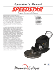
UHS Propane Burnisher
Failure to read and understand this manual before
operating this machine or performing service on this
machine may result in injury to the operator or nearby
personnel or result in damage to the machine or
nearby property. Each operator must be trained in the
operation of this machine before being allowed to use
it. Contact Amano Pioneer Eclipse Customer Service
at 1-800-367-3550 or 1-336-372-8080 or an authorized
Amano Pioneer Eclipse Distributor to inquire about
training or to request a replacement manual.
La falta de leer y de entender este manual antes de
usar esta máquina o de realizar servicio en esta
máquina puede dar lugar a lesión al operador o al
personal próximo o a resultado en daño a la máquina
o propiedad próxima. Cada operador debe ser
entrenado en la operación de esta máquina antes de
ser permitido utilizarla. Ponerse en contacto con el
servicio de Amano Pioneer Eclipse 1-800-367-3550 o
1-336-372-8080 o un distribuidor autorizado por
Amano Pioneer Eclipse para investigar sobre el
entrenamiento o para solicitar un manual.
Manquer de lire et de comprendre ce manuel
d'utilisation avant l'utilisation de cette machine ou
avant faire de maintenance sur la machine peut être
résulter en blessure à l'opérateur ou au personnel
proche ou peut endommagé la machine ou la propriété
proche. Chaque utilisateur doit être entraîné dans
l'opération de cette polisseuse avant l'utilisation.
Veuillez contacter le service àpres-vente de Amano
Pioneer Eclipse à 1-800-367-3550 ou 1-336-372-8080
et/ou un distributeur de Amano Pioneer Eclipse pour
vous renseigner concernant l'entraînement ou pour
obtenir un autre manuel d'utilisation.
DANGER! For your safety, if you smell gas:
1.
2.
3.
4.
Extinguish any open flame.
Open window.
Do not touch electrical switches.
Immediately call your gas supplier.
DANGER!
Do not store or use gasoline or other
flammable vapors and liquids in the vicinity
of this or any other appliance.
Record This Important Information
Date of Purchase
Purchased From
Address
City
State
Phone
Zip
Contact
Machine Model
Machine Serial Number
Important Phone Numbers
Medical Emergency
Police
Fire Department
In this Operation Manual you will find three statements that you must read and observe to ensure
safe operation of this machine.
DANGER! indicates that the possibility of severe bodily injury or death can occur if DANGER!
statements are ignored. Read and observe all DANGER! statements included in the Operation
Manual and attached to the machine.
WARNING! indicates that the possibility of bodily injury to the operator and other people can occur
if WARNING! statements are ignored. Read and observe all WARNING! statements included in the
Operation Manual and attached to the machine.
CAUTION! indicates that the possibility of damage to the machine or other property can occur if
CAUTION! statements are ignored. Read and observe all CAUTION! statements included in the
Operation Manual and attached to the machine.
Contents
Quick Reference Specifications..........................................2
Safety Precautions............................................................ . 3
Machine Preparation......................................................... . 7
Unpacking the Machine.........................................7
Filling the LP Cylinder............................................8
Installing the LP Cylinder.......................................8
Machine Components....................................................... . 9
Controls and Instruments.....................................9
Service Engine Indicator...................................9
High Engine Temperature Indicator......................9
Engine Ignition Switch..........................................10
Engine Bail Throttle.............................................10
Hour Meter...........................................................10
Emergency Stop Switch.......................................10
Pad Change.........................................................11
Fuses.......................................................11
How the Machine Works...................................................12
Pre-Operation Checklist....................................................12
LP Fuel Cylinder................................................................12
Starting the Machine.........................................................13
Burnishing.........................................................................13
Post Operation Checklist..................................................13
Troubleshooting................................................................14
ECU with Engine Monitor and Diagnostic
Software...............................................................14
Engine Fuel Injection Troubleshooting.................16
Machine Troubleshooting.....................................17
Scheduled Maintenance Chart..........................................18
Engine Maintenance.........................................................19
Oil Level Inspection..............................................20
Oil Change...........................................................20
Oil Filter Replacement.........................................21
Spark Plug Inspection and Replacement.............21
Checking and Adding Coolant.............................21
Air Filter Inspection and Replacement.................22
Inspect Fuel Hose and Connections....................22
Inspect Radiator and Hoses................................23
1
Machine Maintenance.......................................................24
Clean Dust Container Filter..................................24
Inspect Pads and Pad Holders............................24
Inspect Drive Belt.................................................24
Replace Drive Belt................................................25
Battery Maintenance............................................25
Body Maintenance................................................26
Machine Storage..................................................26
Repacking the Machine.......................................26
Transporting the Machine....................................26
Machine Specifications.............................................27 & 28
Wiring Schematic.....................................................29 & 30
Electrical Connections..............................................31 & 32
Bulkhead Assembly......................................................33
Frame Assembly..............................................................34
Handle Assembly..............................................................35
Control Panel................................................................36
Bottom Assembly........................................................37& 38
Deck Assembly..........................................................39 & 40
Engine Assembly.......................................................41 & 42
Engine.......................................................................43 & 44
Final Assembly..........................................................45 & 46
Engine Cover Assembly............................................47 & 48
Fuel Injection Assembly....................................................49
Dust Container Assembly..................................................50
Warranty............................................................................52
Quick Reference Specifications:
Capacities:
z Engine Oil:
- Filter not removed: 2L (2.1 U.S. qt.)
- Filter removed: 2.3L (2.4 U.S. qt.)
z Cooling System: 2.7L (2.9 U.S. qt.)
Routine Maintenance Parts:
z
z
z
z
z
z
z
z
z
z
z
Engine Monitor and Diagnostic Software: MP322300
Engine Oil Filter: KA490652078
Engine Primary Air Filter: KA110137020
Engine Secondary Air Filter: KA110137019
Spark Plug: KA920702112
Battery: MP120800
Drive Belt: MP041000 (24”)
MP273000 (28”)
Fuses:
- 20A: SS2570
- 7.5A: MP043000
Dust Skirt: RV022400 (24”)
RV022700 (28”)
Dust Container Filter: MP095100
Pads:
- 24” Blue Blend: PD006024
- 24” White Lightning: PD010024
- 24” Thermal Thunder: PD001024
- 24” Natural Poly-Blend: PD002024
-
28” Blue Blend: PD006028
28” White Lightning: PD010028
28” Thermal Thunder: PD001428
28” Natural Poly-Blend: PD002028
Your Authorized Amano Pioneer Eclipse Distributor
Authorized Amano Pioneer Eclipse Distributor Telephone Number
Amano Pioneer Eclipse Customer Service: 1-800-367-3550
2
Safety Precautions
Anyone operating the machine should read the
following carefully and be informed of potentially
dangerous operating conditions. Operators should be
familiar with the location and use of all safety devices
on the machine. DO NOT use the machine if it is not in
proper operating condition, and report any damage or
operation faults immediately.
DANGER! Operate this machine in a well-ventilated area.
It is the responsibility of the machine operator, machine
owner, and the site manager to ensure that the air
exchange system where the machine is to be used is in
compliance with local building codes and is operating
properly. Failure to operate this machine in a
well-ventilated area could lead to sickness, injury or death
from carbon monoxide (CO) exposure.
DANGER! This machine emits CO, which is a colorless,
odorless, non-irritating gas. The first symptoms of CO
exposure include headache, drowsiness, dizziness, and
nausea. If you should experience any of these symptoms
while operating the machine, shut off the machine and go
outside to get fresh air. Have the machine tested for CO
emissions by a qualified service technician before using it
again.
DANGER! Prolonged or high exposure to CO may result
in vomiting, confusion, and collapse in addition to loss of
consciousness and muscle weakness. If such symptoms
occur, call 911 for emergency medical attention. If you
have experienced these symptoms, DO NOT operate this
machine or any other propane machine again until cleared
by a physician. Excessive exposure to CO can result in
death.
DANGER! Propane is a highly flammable fuel. If you
smell propane, shut off the machine immediately and take
it outside the building. DO NOT use the machine again
until a qualified service technician has corrected the
propane leak. DO NOT use or allow another person to
use an ignition source such as a cigarette lighter near the
propane machine. DO NOT smoke near the propane
machine. DO NOT vent a propane cylinder inside a
building. DO NOT store propane cylinders inside a
building.
DANGER! This machine has parts including the pad
assemblies that can cause severe injury if these parts are
contacted while they are moving. DO NOT allow any part
of the body or clothing to come in contact with these parts
while they are moving. DO NOT try to change the pads
while the machine is running. DO NOT allow other people
to come near the machine while it is in operation. DO
3
NOT allow the machine to run unattended. DO NOT leave
the machine in a place where unauthorized or untrained
personnel could use the machine. DO NOT run the
machine with the pads off center, damaged or missing.
DO NOT run machine with unsecured guards and shields.
DO NOT operate the machine if the machine has loose
parts.
DANGER! Federal law and California State law prohibits
the following acts or the causing thereof: (1) the removal
or rendering inoperative by any person other than for
purposes of maintenance, repair, or replacement, of any
device or element of design incorporated into any new
engine for the purpose of emission control prior to its sale
or delivery to the ultimate purchaser or while it is in use, or
(2) the use of the engine after such device or element of
design has been removed or rendered inoperative by any
person.
Among those acts presumed to constitute tampering are
the acts listed below: DO NOT tamper with the original
emission related part.
z Throttle body and internal parts
z Spark plugs
z Magneto or electronic ignition system
z Air cleaner elements
z Crankcase
z Cylinder heads
z Breather chamber and internal parts
z Intake pipe and tube
z Regulator
z Fuel injector
z Fuel lock-off
WARNING! Overfilled or liquid withdraw cylinders can
damage the fuel system and create a fire hazard. DO
NOT overfill the cylinder or use a liquid withdraw cylinder
on the machine. If the regulator freezes or the machine
shuts down due to a "System Rich" fault (See "Controls
and Instrumentation" Section), stop the burnisher and take
the cylinder outside. Inspect cylinder, if a vapor withdraw
cylinder, use gloves or pliers to open bleeder valve and
purge cylinder until only vapor is escaping. If it is a liquid
withdraw cylinder, replace with a vapor withdraw cylinder.
Both cylinders are shown below.
WARNING! Modifications or alterations to this machine
can lead to personal injury or damage to the machine. DO
NOT make unauthorized modifications or alterations to this
machine. Amano Pioneer Eclipse assumes no liabilities
for injury or damage resulting from an unauthorized
modification or alteration to the machine. Any
unauthorized modification or alteration to this machine
voids all warranties.
WARNING! The muffler and the engine become hot
enough while the machine is in operation, and for a long
time after the machine is shut off, to cause severe burns.
DO NOT touch these parts of the machine until they have
cooled.
WARNING! Injury can occur to the eyes and body while
using the machine. Safety goggles, safety shoes, and
safety clothing are recommended while operating the
machine.
WARNING! Continuous exposure to high noise levels can
cause hearing loss. Hearing protection is recommended
while the machine is in operation.
WARNING! Machine vibration may cause tingling or
numbness in the fingers or hands. Gloves are
recommended to reduce machine vibration. If tingling or
numbness persists, shut off the machine. If the vibration is
caused by loose parts such as an off center pad, adjust or
tighten these parts before using the machine again.
CAUTION! A dirty engine filter can cause overheating.
Check and replace following recommended maintenance
schedule.
CAUTION! Overheating can be caused by insufficient or
low oil. Check oil before each use, and fill or change as
needed.
CAUTION! Never over-fill with oil. Over-filling could cause
irreparable damage to the engine.
CAUTION! Overheating can be caused by dirty oil. Check
oil before each use and change regularly following
recommended maintenance schedule.
CAUTION! DO NOT engage starter for more than 10
seconds. Allow a 60 second cool-down period for second
failed start-up attempt.
CAUTION! Perform all recommended scheduled
maintenance. Regular maintenance of your propane
powered floor machine is necessary to keep it in safe
working condition.
CAUTION! DO NOT operate machine unless trained and
authorized. DO NOT operate machine unless you have
read and understand the operation manual. DO NOT
operate machine in flammable or explosive areas.
CAUTION! Before starting machine ensure all safety
devices are in place and functioning properly. Before
starting machine check for proper operation.
CAUTION! When using machine, go slowly on inclines or
slippery surfaces. Use care when operating machine in
reverse.
CAUTION! When servicing machine, stay clear of moving
parts. DO NOT wear loose clothing when working on
machine. Block machine wheels before raising or jacking
up machine. Use hoist stands that will support the weight
of the machine. Wear eye and ear protection when using
pressurized air or water. Disconnect battery connections
before servicing machine. Use only replacement parts
supplied by Amano Pioneer Eclipse or an Amano Pioneer
Eclipse Authorized Distributor or Service Center.
CAUTION! When loading or unloading machine onto or off
a truck or trailer, turn machine OFF. Only use a truck or
trailer that will support the weight of the machine to
transport. DO NOT push the machine onto or off a truck or
trailer unless the load height is 15 in (380mm) or less from
the ground. Block machine wheels when transporting. Tie
the machine down securely to truck or trailer when
transporting.
4
This machine is manufactured for
commercial use only.
This machine is designed and manufactured for indoor use
in burnishing wax coated hard floor surfaces. Amano
Pioneer Eclipse does not recommend use of this machine
in any environment other than an indoor environment.
This propane powered floor machine is designed and
manufactured for commercial floor burnishing only. This
machine is designed to burnish most modern types of
floors including composition tile, stone, marble, terrazzo,
and resilient floor covering, and some coated wood floors.
Even though NFPA 58 8-4.5 says..."these machines shall
be permitted to be used in buildings frequented by the
public, including the times when such buildings are
occupied by the public," Amano Pioneer Eclipse suggests
usage when occupancy of a given work area is minimal.
Protection Association (NFPA) Standard for Storage and
Handling of LP Gas is the appropriate authority for safe
propane use. A copy of this publication is available through
the National Fire Protection Association (1-800-344-3555).
Canadian Safety Requirements
1.
2.
3.
These machines should not be used
z
z
z
z
In nursing homes, hospitals, day-care centers, etc.
By unqualified or untrained personnel.
Unless properly maintained and adjusted.
On areas with obstructions such as thresholds,
floor outlet boxes, etc.
z In areas where loose tile or other objects are
present.
z In rooms without proper ventilation.
4.
Refueling and Storage of Fuel Cylinders
The Revolution uses a 20lb (9.1kg) capacity aluminum or
steel cylinder, which meets the DOT 4E240 standards.
These cylinders are also listed by UL. In addition, the
steel cylinder meets European TPED specifications and is
CE compliant. Filling should be done ONLY by a qualified
propane dealer. FILL THROUGH THE SERVICE VALVE
ONLY. A properly filled cylinder should not exceed 80% of
the rated capacity. DO NOT attempt cylinder repair.
Return the cylinder to your propane dealer if repair is
necessary. Please note that DOT regulations prohibit
shipping of cylinders after the cylinder has been filled with
propane. When not in use, cylinders always should be
stored outside in an upright position in a secure, tamperproof, steel mesh storage cabinet. The cabinet may be
located next to the building, but with at least five feet (1.5
m) of space between the cabinet and the nearest building
opening (door or window). The cylinder to be used on the
Revolution is a vapor withdraw cylinder. It is not
intended to be used with a liquid withdraw system.
Conversely, a liquid withdraw cylinder is not to be
used with this machine. The use of a liquid withdraw
cylinder on a vapor withdraw system could freeze the
regulator and create a fire hazard. The National Fire
5
5.
6.
7.
A sign indicating "NO SMOKING" shall be
permanently displayed at the storage area. The
sign shall be in accordance with the sign required
in Clause 10.12.3 of CAN/CGA-B149.2-M91,
Propane Installation Code.
When the cylinder is attached to the floor
maintenance machine for use, the operator shall
not leave the unit unattended except for short
periods of time such as rest stops, washroom, or
meal stops.
The requirements of 1.10.1 (e) and (g) do not
apply in industrial buildings.
A floor maintenance machine shall only be used in
buildings:
a.
Provided with continuous mechanical
ventilation that removes products of
combustion to the outdoors of not less that
300 CFM for each 10,000 BTU-hr or
fraction thereof.
b.
Provided with natural ventilation of not
less than 300 CFM for each 10,000
BTU-hr input or fraction thereof, based on
a maximum of one-quarter-air exchange
per hour for the net building volume.
The owner of a floor maintenance machine shall
ensure that the operator has participated in a
course authorized by the manufacturer of the unit
on the safe handling of propane and the safe
operation of the machine.
The owner of a floor maintenance machine shall
ensure that the unit is maintained in accordance
with the manufacturer's recommended
maintenance procedures in a safe operating
condition and the owner shall maintain a record of
the maintenance for a period of two years.
Before transporting a floor maintenance machine,
the cylinder shall be securely fastened with the
system valve closed, and the cylinder shall be
located in a well-ventilated space.
Operator Responsibility
The operator is responsible for performing the
recommended daily maintenance and checkups of the
machine to keep it in good working condition. The operator
must inform the service mechanic or supervisor when
recommended maintenance procedures are required as
described in the MAINTENANCE section of this manual.
z
All machines are tested while stationary and
centered on the test surface. With the traction
drive in neutral (where applicable) the test is
conducted with the machine at maximum engine
or motor speed as specified by the manufacturer.
z
The operator is located in the normal operating
position with the microphone or meter supported
independent of the machine, 1,68 m (66 in) above
the test surface, 25 cm (10 in) to the right and left
centerline of the operators position, and 20 cm
(8 in) to the rearmost point of the handle, with the
handle in the most forward position.
z
The sound level meter is observed for a minimum
of 5 seconds or until a stabilized reading is
obtained. The maximum repeatable sound level
observed during the test at each microphone
position is recorded and documented.
Read this manual carefully before operating this machine.
FOR SAFETY: DO NOT operate machine before reading
and understanding the operation manual.
Check the machine for shipping damage.
Keep your machine regularly maintained by following the
maintenance information in this manual. We recommend
taking advantage of a service contract from your Amano
Pioneer Eclipse Authorized Distributor or Service Center.
Order parts and supplies only from an Authorized Amano
Pioneer Eclipse Distributor. Use the parts illustration
section of your manual when ordering parts.
During and after operation, perform the recommended
daily and hourly procedures outlined in the Maintenance
Chart.
Test for Operator-Ear Sound Pressure Level
Amano Pioneer Eclipse measures and rates the operatorear sound pressure level for hand-guided floor treatment
and floor cleaning machines for industrial use. All tests
are performed in accordance with European Machinery
Directive (98/37/EC).
z
z
Outdoor test area consists of a flat open space
free from effects of signboards, buildings or
hillsides for at least 15 m (50 ft) from the center of
the test surface. Indoor tests are conducted in a
semi-anechoic or sound deadening room.
The test surface is a single sheet of floor covering
at least 1 m (3.3 ft) wider and longer than the
equipment being tested. In order to not affect the
sound reading, the observer taking readings is at
least 2 m (6.6 ft.) from the equipment being tested,
or standing directly behind the operator.
Test for Hand-Arm Vibration at the Grip
Surface of Hand-Guided Machinery
Amano Pioneer Eclipse measures and rates the vibration
at the machine-hand contact surface of hand-guided
machines that are provided with handles in accordance
with European Machinery Directive (98/37/EC).
z
The test area consists of a flat open floor area
that allows the machine to be operated normally.
z
The transducer is mounted firmly at a point
halfway along the length of the handle where the
handle would normally be held.
z
Machines are tested while stationary, with all
mechanisms necessary for the equipment to
perform its intended functions engaged and the
traction drive in neutral (if applicable). The
machine will be tested at maximum engine or
motor speed as specified by the manufacturer of
the subject machine.
z
The measurements are recorded from the
dominant axis.
6
7.
Open engine cover.
8.
Remove engine air scoop and connect the battery.
Refer to Maintenance section.
9.
Check machine fluid levels (engine oil and
coolant). See Maintenance section. Note: If
machine was shipped by airfreight, add engine
oil.
Carefully back the machine off of the pallet.
Machine Preparation
Unpacking the Machine
The machine is shipped boxed on a wooden pallet. To
unpack machine:
1.
2.
3.
4.
5.
Cut and remove black bands holding the box to
the pallet.
Remove staples attaching the box to the platform
at the bottom edge of the box.
With two people, one at either end of the box, lift
box straight up and off machine.
Cut and remove black bands securing the
machine to the pallet.
Remove back brace.
10.
6.
7
Remove front wheel brace.
Filling the LP Cylinder
Installing the LP Cylinder
The Revolution uses the 20lb (9.1 kg) capacity cylinder,
which meets the D.O.T. 4E240 standards. These cylinders
are also listed by UL. In addition, the steel cylinder meets
European TPED specifications and is CE compliant.
Filling should be done ONLY by a qualified propane dealer.
A properly filled cylinder should not exceed 80% of the
rated capacity. Do not overfill the cylinder or use a liquid
withdraw cylinder on the machine. The use of a liquid
withdraw cylinder on a vapor withdraw system could freeze
the regulator and create a fire hazard.
Place the Safe-Fill cylinder on the cylinder platform at the
back of the machine. Connect the fuel hose coupling to
the service valve by turning to the right (clockwise). HAND
TIGHTEN ONLY! Make sure coupling is not cross
threaded and check for leakage by noting any propane
odors immediately after cylinder is connected. Finally,
connect the two ends of the tank strap together.
®
To Remove the LP Cylinder, reverse the above
procedure. Always connect or change cylinders in a
well-ventilated area.
8
Controls and Instruments
Service
Engine
Indicator
Hour
Meter
Emergency
Stop
Button
Service Engine Indicator
Engine
Shutdown
Indicator
Key
Switch
Service Engine Indicator
The Revolution has an onboard ECU that monitors and
controls the engine’s fuel system. If a problem occurs, the
Service Engine Indicator alerts the operator with a series
of blink codes. This is explained further in the
Maintenance section.
Engine Shutdown Indicator
If the engine shuts down abnormally, a LED will light. If
this occurs, stop the machine immediately and refer to the
“Machine Troubleshooting” section in this manual.
Engine Shutdown Indicator
9
Engine Ignition Switch
The Revolution features a key switch ignition.
Start: Turn the key all the way clockwise or START to
engage the engine starter motor. Release the key when
the engine starts.
Note: If the engine is cold, start the engine with the bail
throttle pulled back.
Off: Turn the key to the back or OFF position.
Note: For safety, always close the propane cylinder valve
to stop the engine and then turn the key switch to the OFF
position.
and every 100 hours thereafter. At these intervals the
meter will flash “OIL” for service. The meter will begin
flashing one hour before recommended service interval
and continue until one hour past the recommended service
interval. The meter will reset itself after the preset interval
has passed.
Emergency Stop
Engine Bail Throttle
The engine bail throttle controls the engine speed and
engages the burnish clutch. To increase engine speed
and engage clutch, pull the bail back.
The emergency stop is provided for added safety. To
disable the machine, press the red button.
CAUTION! The emergency stop should only be used in
the event of an emergency or for added safety after the
machine has been shut down. The engine should be
stopped by closing the propane cylinder valve and turning
off the key switch.
Hour Meter
The hour meter records the number of hours the machine
has been powered ON. The hour meter reading is used to
mark recommended maintenance intervals. The hour
meter alerts the operator when the machine requires
scheduled maintenance. This occurs after the first 8 hours
10
Pad Change
1.
2.
3.
4.
Close the valve on the propane cylinder, allow the
engine to stop and turn the machine OFF.
Remove the propane tank.
Rock the machine back by either pushing down on
the operator handle or lifting up the front of the
machine.
Remove centering device and inspect pads. If
pads have worn less than 1/4” (6mm), replace
them.
Fuses
The machine’s electrical circuit is protected by fuses,
which stop the flow of current in the event of a circuit
overload. Once a fuse blows, it must be replaced. If the
overload that caused the fuse to fail is still present, the
new fuse will fail and the problem must be corrected. DO
NOT bypass any fuse. The fuse panel is located on the
right side of the bulkhead.
Fuel
Lock-Off
Clutch
Circuit
Fuel
Injection
Charging
Regulator
The primary fuses are located on the right side of the
engine near the starter motor.
Ignition Fuse
Primary Fuse
11
How the Machine Works
Installing the LP Cylinder
The Revolution is a propane burnisher that has a pad
driver that is belt driven via an electric clutch. The clutch
is controlled by a bail on the handle. Dust generated
during burnishing is contained by a floating steel skirt and
collected in a dust container.
Place the Safe-Fill cylinder on the cylinder platform at the
back of the machine. Connect the fuel hose coupling to
the service valve by turning to the right (clockwise). HAND
TIGHTEN ONLY! Make sure coupling is not cross
threaded and check for leakage by noting any propane
odors immediately after cylinder is connected. Finally,
connect the two ends of the tank strap together.
Pre-Operation Checklist
z
z
z
z
z
®
Check the engine oil level. Add oil if needed.
Refer to Maintenance.
Check the engine coolant level. Add coolant if
needed. Refer to Maintenance.
Inspect the engine radiator and clean off any
debris or dust buildup. Refer to Maintenance.
Inspect the burnishing pad and replace, if
necessary. Refer to Maintenance.
Inspect the pad holder for cracks or damage!
Replace if necessary. Refer to Maintenance.
WARNING! A DAMAGED PAD HOLDER ROTATING AT
HIGH SPEEDS MAY BE AN EXTREME HAZARD IF IT
SHOULD DISINTEGRATE.
z
z
Inspect the drive belt. Replace if necessary.
Refer to Maintenance.
Check the machine for leaks or loose fasteners.
Only Use a Vapor Cylinder!
LP Fuel Cylinder
The Revolution uses the 20 lb (9.1 kg) capacity cylinder,
which meets the D.O.T. 4E240 standards. These cylinders
are also listed by UL. In addition, the steel cylinder meets
European TPED specifications and is CE compliant.
Filling should be done ONLY by a qualified propane dealer.
A properly filled cylinder should not exceed 80% of the
rated capacity. Do not overfill the cylinder or use a liquid
withdraw cylinder on the machine. The use of a liquid
withdraw cylinder on a vapor withdraw system could freeze
the regulator and create a fire hazard.
Pressure
Relief
Valve
Bleeder
Valve
Liquid
Level
Sight
Gauge
Service
Valve
12
Starting the Machine
1.
2.
Complete your pre-operation check.
Turn propane cylinder service valve
counter-clockwise to open.
Note: Always open the service valve slowly to allow
pressure to equalize in the hoses. Opening the service
valve too quickly may cause the flow check valve to
engage, limiting the fuel flow.
3.
With the engine bail throttle pulled back, engage
the starter by turning the key switch to the starting
position for approximately 5 seconds. If the
engine does not start, release the key switch for
10 seconds, then try to start again for another 5
seconds.
4.
After the engine has started, allow the engine to
warm up for approximately 30 seconds. For
optimum performance, only burnish at the full
throttle position.
Note: The Revolution comes with an onboard ECU that
continually monitors and controls the engine's fuel injection
system. In addition, the machine is equipped with a
catalytic muffler. The Service Engine light will NOT be
illuminated as long as the machine is safely and properly
operating. Refer to the "Machine Troubleshooting" section,
if the Service Engine light flashes.
WARNING! Catalytic mufflers require a few minutes to
warm up before effectively removing harmful emissions.
Make sure of proper ventilation during this warm-up
period!
Burnishing
1.
2.
Dust mop and scrub the floor to clean it.
After the engine has been started and properly
warmed, pull back on the bail throttle to increase
engine speed and engage the clutch.
3.
Lower the burnishing head to the floor while
moving the machine forward.
Note: The burnisher should always be operated at full
throttle engagement to ensure adequate air movement
through the cooling radiator.
4.
Try to burnish in open areas with minimal
obstructions. Use a smaller burnisher for more
confined areas.
CAUTION! Keep the burnisher moving when the
burnishing head is rotating. Failure to do this may result in
finish damage.
CAUTION! DO NOT add weight to the burnisher head.
CAUTION! DO NOT lift up on the handle to add pressure
while burnishing.
Note: To not comply with any of the CAUTION!
statements could cause the engine to overheat and/or
damage the padholder, drive components or dust skirt.
5.
When done burnishing, push the machine to the
desired location. Turn off the LP cylinder service
valve. When the fuel is depleted and the engine
stops, turn the key switch OFF.
6.
Remove the LP cylinder and store properly. Refer
to Refueling and Storage of Fuel Cylinders.
Post Operation Checklist
z
z
z
13
Turn off the LP cylinder service valve. When the fuel
is depleted and the engine stops, turn the key switch
OFF.
Check the dust container and dust filter. Empty the
container and clean the filter, if necessary. Refer to
Maintenance.
Check under the machine for leaks and loose
fasteners.
Troubleshooting
ECU with Engine Monitor and Diagnostic
Software
The Revolution comes with an onboard ECU that
continually monitors and controls the engine's fuel injection
system. The engine may be diagnosed by two methods.
The first is by the blink codes that are displayed by the
Service Engine Indicator on the control panel. The Service
Engine Indicator will blink two digit fault codes to indicate
engine problems. Blink codes are shown below. The
system blinks the first digit of the code, followed by a
pause, then the last digit. This will be followed by a long
blink and then the sequence will begin again. For
example, a “System Rich” failure would have the following
code: one blink, pause, and two blinks. A “Low Battery
Voltage” failure would have the following code: five blinks,
pause, and one blink.
A more detailed evaluation may be found using the Engine
Monitor and Diagnostic Software that is available for the
Revolution. The software’s display can be seen on the
next page.
To view, load the software on a computer according to the
instructions on the software CD. Next, connect the engine
ECU to the computer via a nine-pin serial cable and
communication box.
The software gives a more detailed description of the fault.
In addition, it displays critical engine parameters, including
engine RPM.
14
Engine Monitor and Diagnostic Software
Display Explanation
1.
2.
3.
4.
5.
6.
7.
8.
9.
10.
11.
12.
13.
14.
15.
16.
17.
18.
19.
15
Operating Mode: Tells operational status of Engine Monitoring Software.
Start Now: Click this buttion to start the Engine Monitor Software.
Tachometer: This measures the real time engine speed.
Oil Pressure: Displays if the Engine Oil Pressure is normal.
O2 Sensor: Displays the Oxygen Sensor’s voltage signal. This measures the oxygen content of the exhaust,
which the ECU uses to constantly adjust the desired Air/Fuel Ratio.
MAP Sensor: Manifold Absolute Pressure is the engine’s intake vacuum. The ECU monitors this to determine
engine load.
Engine Temp: Displays if the Engine Temperature is normal or too high.
Average Engine Speed: Displays the average Engine Speed.
Battery Voltage: Displays the charging system’s voltage.
Oxy-Correction: Displays fuel correction percentagee to achieve desired performance and emissions.
Oxy-Wait: Displays the Fuel Correction Rate.
Final Fuel Quantity: Displays the volume of fuel being delivered to the engine.
Injector Duration: Displays the duration the injector is injecting fuel.
MIL Light: Displays if the Service Engine Indicator light is ON or OFF.
Shut-Down Light: Displays if the Engine Shutdown light is ON or OFF.
Lockoff Valve: Displays if the Fuel Lock is Open or Closed.
Diagnostic Code: Displays Engine Fault code.
Air/Fuel Gauge: Displays the Air Fuel Mixture.
RPM Gauge: Displays the Engine RPM.
Engine Fuel Injection Troubleshooting
16
Machine Troubleshooting
17
Scheduled Maintenance
18
Maintenance
1.
After the engine cover has been removed, remove
the two front engine air scoop retaining knobs.
2.
Push in the sides of the engine air scoop and slide
forward.
3.
Remove the engine air scoop.
Engine
Note: For all maintenance procedures requiring the
engine cover to be removed, please perform the following.
1.
Push the machine to a level surface, turn off the
LP cylinder, and remove it.
2.
Open the cover by lifting up on the hand cutout.
3.
Unlatch the lanyard, lower the cover, and lift
straight up.
Note: For all maintenance procedures requiring the
engine air scoop to be removed, please perform the
following.
19
Oil Level Inspection
1.
2.
3.
4.
5.
Push machine to level surface.
Turn off LP cylinder and remove it.
Open the engine cover.
Clean area around the oil gauge (A) before
removing it.
Remove the oil gauge and wipe it with a clean
cloth.
Oil Drain Hose
6.
7.
6.
The machine should be in an upright, level
position. If necessary, place a block under the
back of the machine or apply weight to the front of
the deck to maintain an upright, level position.
7.
Insert the oil gauge into the tube (B), but do not
tighten the oil gauge.
8.
Check the oil level. It should be between the
“FULL” (C) and “ADD” (D) marks on the oil gauge.
Note: If the oil level is near or below the "ADD" mark,
remove the oil gauge and add enough engine oil to bring
oil level to the "FULL" mark.
Note: If the oil level is too high, remove the excess oil by
loosening the oil drain valve.
CAUTION! Do not fill above the "FULL" mark. Excess oil
will cause a smoking condition and may cause the engine
to overheat.
Oil Change
1.
2.
3.
4.
5.
Change the oil after the first 8 hours of operation
and every 100 hours thereafter.
Start and warm the engine so the oil will drain
easily and completely. Push machine to a level
surface. Stop the engine.
Turn off LP cylinder and remove it.
Remove the engine cover.
Remove the oil drain hose from the retaining clip,
and remove the plug from the end of the hose.
Place a suitable container under the end of the oil
drain hose.
Open the drain valve by turning counter-clockwise
and drain the oil.
Oil Drain Valve
WARNING! Be careful with hot oil being drained. It may
be hot enough to cause severe burns.
8.
Close the drain valve by turning clockwise.
9.
Remove oil cap and add clean SH or SJ SAE 30
oil. Use 2.1 U.S. qt. (2.0 L) when the filter is not
changed and 2.4 U.S. qt. (2.3 L) when filter is
changed.
10. Screw in oil gauge. Reconnect the LP cylinder to
the fuel hose.
11. Run the engine at low idle for 2 minutes. Check
for leaks around the engine.
12. Stop the engine. Check the oil level (see Oil Level
Inspection section).
20
Oil Filter Replacement
1.
2.
3.
4.
5.
Place a suitable container underneath the oil filter.
Using a strap wrench or oil filter wrench, remove
the oil filter. Turn the filter counter-clockwise to
remove it.
Apply a thin coat of new oil or grease to the oil
filter seal (A).
Install the new filter (Amano Pioneer Eclipse part
# KA920652078) by turning it clockwise.
Turn the filter until the seal contacts the mounting
surface (B) of the engine. Then, turn the filter BY
HAND 3/4 turn more.
A:
B:
C:
D:
Insulator
Center Electrode
Plug Gap
Side Electrode
Checking and Adding Coolant
6.
7.
8.
Reconnect the LP cylinder to the fuel hose.
Run the engine at low idle for 2 minutes. Check
for leaks around the engine.
Stop the engine. Check the oil level (see Oil Level
Inspection section).
Spark Plug Inspection and Replacement
1.
2.
3.
4.
Turn off LP cylinder and remove it.
Open the engine cover.
Pull spark plug cap off of spark plug.
Remove spark plug by turning counter-clockwise
and inspect it.
Note: If the plug is oily or has carbon build up on it, clean
the plug using a high flash-point solvent and a wire brush
or other suitable tool.
Note: If the spark plug electrodes are corroded or
damaged, or if the insulator is cracked, replace the plug.
Use Only Amano Pioneer Eclipse part # KA920702112.
Do not use any other spark plug!
5.
Measure the gap with a wire-type thickness
gauge. The correct gap is .025 in (.635 mm). If
the gap is incorrect, carefully bend the side
electrode with a suitable tool to obtain the correct
gap.
1.
Push machine to level surface.
2.
Turn off LP cylinder and remove it.
3.
Remove the engine cover.
4.
Remove the engine air scoop.
WARNING! Always allow the engine to cool before
removing the radiator cap. Then remove the cap slowly
and carefully to avoid a possible fast discharge of hot
coolant which could cause severe burns.
5.
Remove the radiator cap by turning it counterclockwise and check the coolant level in the
radiator.
6.
Coolant must be level with the filler neck bottom
(A) and between the high and low marks on the
reserve tank. If additional coolant is required, use
only 50% mix of permanent type antifreeze for
aluminum engine and radiator. Completely empty,
the system requires 2.9 U.S. qt ( 2.7 L).
CAUTION! Use only soft or distilled water for the
antifreeze mix in the cooling system. If hard water is used,
it causes scale accumulation in the water passages and
reduces the efficiency of the cooling system.
7.
21
Install the radiator cap by pushing it down and
turning it clockwise.
Air Filter Inspection and Replacement
1.
2.
3.
4.
Push machine to level surface.
Turn off LP cylinder and remove it.
Open the engine cover.
Locate the air cleaner housing, unhook the two
clips (A), and remove the cap (B).
Inspect Fuel Hose and Connections
1.
2.
3.
4.
5.
(A)
Push machine to level surface.
Turn off LP cylinder and remove it.
Remove the engine cover.
Inspect hoses for abrasions and other signs of
wear. Replace all worn or damaged hoses.
Check for gas leaks by spreading a soapy water
solution around all connections while the LP
cylinder is reconnected and the service valve is
turned ON.
Check for Leaks
(B)
5.
Remove primary filter (A) and secondary filter (B).
6.
CAUTION! Do not wash the air cleaner filters. Do not
oil the air filters. Do not use pressurized air to clean
the air filters.
6.
Inspect both primary and secondary air filters. If
necessary, clean primary filter by lightly tapping
and wipe seal ends with a clean cloth. If primary
filter cannot be cleaned, is bent, or damaged, it
must be replaced (Amano Pioneer Eclipse part #
KA110137020). If secondary filter is dirty, do
not attempt to clean it. Replace it with a new filter
(Amano Pioneer Eclipse part # KA110137019).
7.
Clean the housing with detergent and water and
dry thoroughly.
8.
Check the housing for cracks or other damage.
The housing must seal well and permit only filtered
air to the carburetor.
9.
Slide the secondary and primary filters into place
in the air cleaner housing.
10. Install the cap and fasten the two clips.
7.
If a leak is detected, turn off the LP cylinder. If the
leak is in a hose, replace it. If the leak is at a
fitting, loosen and clean it. Apply pipe-sealing
compound and re-tighten it.
Recheck for leaks using a soapy water solution. If
leaks persist at fittings, replace them and recheck
with a soapy water solution once more.
22
Inspect Radiator and Hoses
1.
2.
3.
4.
5.
Push machine to level surface.
Turn off LP cylinder and remove it.
Remove the engine cover.
Remove the engine air scoop.
Check the radiator core. If the corrugated fins are
deformed, carefully straighten them with the blade
of a thin screwdriver.
Check and adjust valve clearance.
Re-torque heads:
Refer to Kawasaki’s FD731V service manual.
Clean and lap valve-seating surface:
Refer to Kawasaki’s FD731V service manual.
Change coolant:
Refer to Kawasaki’s FD731V service manual.
6.
7.
Inspect the inlet and outlet tubes for cracks, kinks,
dents, and fractured seams. Repair or replace
(refer to Kawasaki’s FD731V service manual), if
necessary.
Check for debris that can be lodged in the radiator.
Clean them out by using compressed air or a lowpressure washer.
CAUTION! Using high-pressure water could damage
the radiator fins and impair the radiator’s
effectiveness.
23
5.
Maintenance
Machine
Clean Dust Container Filter
1.
2.
3.
Push machine to level surface.
Turn off LP cylinder and remove it.
Loosen the Velcro strap used to retain the dust
container and pull out the dust container.
Velcro Strap
4.
Loosen the dust filter retainer knob and remove
the dust filter retainer.
Inspect the pad holder for cracks or damage. If
the pad holder does not have any damage
proceed to step 9.
WARNING! A damaged pad holder rotating at a high rate
of speed may be an extreme hazard if it should come
apart.
6.
If the pad holder needs to be removed, a 3/4”
wrench will be required. Locate the wrench flats
on top of the spindle shaft by routing the wrench
through the front grill and onto the top side of the
spindle pulley. With the spindle shaft secure, turn
the pad holder counter clockwise until it is free of
the spindle shaft.
7.
Save the washer and/or spacer that is on the
spindle shaft. Be sure they are in place when the
pad holder is re-installed.
8.
When threading the pad holder onto the spindle
shaft, use the wrench to keep the shaft from
turning. Be sure the pad holder is tight before
proceeding.
9.
Secure the pad with the centering device.
10. Lower the machine.
Inspect Drive Belt
1.
2.
3.
4.
Filter
Retaining
Knob
5.
Push machine to level surface.
Turn off LP cylinder and remove it.
Rock the machine back by either pushing down on
the operator handle or lifting up the front of the
machine.
Lie on the floor and look at the belt above and
behind the shroud. Rotate the pad drive and
inspect the belt.
If cracks or excessive wear is present, replace
with MP041000 (24” Revolution) or MP273000
(28” Revolution).
5.
Pull the dust filter from the container and clean the
filter by either tapping the filter on the inside of a
waste container or using a vacuum cleaner.
6.
Empty the debris in the container and wipe clean.
Note: Do not use compressed air or water to clean the
dust filter. This will damage or destroy the filter and
require it to be replaced.
7.
Replace the filter and secure with filter retainer.
Place dust container on the machine and secure
with the Velcro strap.
Inspect Pads and Pad Holders
1.
2.
3.
4.
Push machine to level surface.
Turn off LP cylinder and remove it.
Rock the machine back by either pushing down on
the operator handle or lifting up the front of the
machine.
Remove centering device and inspect pads. If
pads have worn less than 1/4” (6 mm), replace
them.
24
Replace Drive Belt
1.
2.
3.
4.
Push machine to level surface.
Turn off LP cylinder and remove it.
Remove the engine cover.
Remove the front grill.
7.
8.
9.
10.
11.
Pull the belt out from the front of the machine.
Install new belt on the engine clutch pulley.
Route belt around tensioner pulley and start belt
on the spindle pulley.
Slowly turn the pad drive and guide the belt
completely around the spindle pulley.
Reattach the belt cover, front grill, and engine
cover.
Battery Maintenance
The battery supplied with this machine is a sealed,
absorbed glass mat (AGM), maintenance free type. It
never needs servicing. When battery replacement is
necessary, use Amano Pioneer Eclipse part #: MP120800.
5.
Remove the belt cover.
1.
2.
3.
4.
5.
Push machine to level surface.
Turn off LP cylinder and remove it.
Raise the body.
Remove the engine cover.
Remove the engine air scoop.
6.
Disconnect the BLACK negative battery cable first.
Disconnect the RED positive battery cable last.
Loosen battery-retaining strap.
Lift out old battery and replace with new battery.
Secure battery with battery-retaining strap.
Connect the RED positive battery cable first.
Connect the BLACK negative battery cable last.
Attach engine air scoop, and engine cover.
7.
8.
9.
10.
11.
6.
25
Use a straight blade screwdriver under the belt
and over the spindle pulley. Slowly turn the pad
driver while guiding the belt off of the pulley.
z
z
z
PROPOSITION 65 WARNING
Battery posts, terminals, and related
accessories contain lead and lead
compounds, chemicals known to the State of
California to cause cancer and reproductive
harm.
Batteries also contain other chemicals known
to the State of California to cause cancer.
Wash hands after handling.
Body Maintenance
The body may be cleaned with a damp cloth to remove
dust and scuff marks. More stubborn scuffmarks on the
body exterior can be removed with a vinyl cleaner.
Repacking the Machine
Refer to Unpacking and repack the machine using original
packing materials and container.
Transporting the Machine
When transporting a propane powered floor machine with
the fuel cylinder installed, the cylinder should be securely
fastened with the service valve closed and the machine
should be secured in the vehicle. Any propane fuel
cylinders not installed should be securely fastened to avoid
movement and damage. Never store machine with
cylinder installed or store spare cylinders in an enclosed
van or trailer. It is a good practice to check propane
cylinders for overfilling before transporting them. If
overfilled, correct before loading them in the vehicle by
venting the excess propane outside in a safe area using
the bleeder valve.
Machine Storage
Only authorized, trained personnel should have access to
propane cylinders and machines.
1.
2.
3.
4.
5.
6.
7.
Remove propane fuel cylinder when not in use
and store it outside in a storage cage in
accordance with NFPA Section 5 or Subsection
9.5.2 of CAN/CGAB149.2. Do not release or
bleed propane inside the building. Please consult
your local Fire Marshal to ensure that you are in
compliance with local fire codes.
Store machine away from objects that may fall and
damage it.
Never store machine or fuel cylinders near an
open flame or heat-producing device.
Make sure machine is cleaned properly before
storing.
Never store machine with cylinders installed, or
store spare cylinders in an enclosed van or trailer.
Store machine in a dry location, temperature not to
exceed 120°F (50°C).
Never store machine with body opened.
26
Machine Specifications
Productivity
Burnishing Rate:
2
2
28”: 34,000 ft2/hr (3,159 m2/hr)
24”: 28,000 ft /hr (2,601 m /hr)
Engine
Engine: Kawasaki FD731V, 675 cc, watercooled.
Fuel System: Electronic fuel injection with
engine and emissions monitoring system.
Engine Speed, Idle: 1,800-2,000 rpm
Engine Speed, High Idle: 2,800-2,900 rpm
Coolant Capacity: 2.9 U.S. qt. (2.7 L)
Spark Plug Part #: KA920702112
Spark Plug Gap: 0.025 in (0.635 mm)
Engine Primary Filter: KA110137020
Engine Secondary Filter: KA11013-7019
LP Cylinder Type: 20 lb (9.1 kg) vapor withdraw
Engine Oil: SAE 30W SH or SJ
LP Cylinder Part #: (North America Only):
MP021703 (Aluminum) MP106000 (Steel)
Engine Oil Capacity, Filter Not Removed: 2.1
U.S. qt (2 L)
Engine Monitor and Diagnostic Software:
MP322300
Engine Oil Capacity, Filter Removed: 2.4 U.S. qt
(2.3 L)
27
Coolant: Permanent type of antifreeze for
aluminum engine. Mixed 50%.
Machine Specifications
Deck Drive
Drive: Electric clutch with B-Section Belt.
Clutch: MP220000
Drive Belt: 28”: MP273000
24”: MP041000
Dust Container Filter: MP095100
Recommended Pads:
z 24” Blue Blend: PD006024
z 24” White Lightning: PD010024
z 24” Thermal Thunder: PD001024
z 24” Natural Poly-Blend: PD002024
z
z
z
z
28” Blue Blend: PD006028
28” White Lightning: PD010028
28” Thermal Thunder: PD001428
28” Natural Poly-Blend: PD002028
Pad Holder Assembly: 28”: MP032500-DOM 24”: MP047500-DOM
MP183700-EJ
MP196600-EJ
Literature
FD731V Kawasaki Parts Catalog: KA99907258801
FD731V Kawasaki Service Manual: KA99924206501
Electrical
Battery Type: 12V, 275 CCA, AGM starter battery
Battery Part #: MP120800
20A Fuse: SS2570
7.5A Fuse: MP043000
Size
Weight: R280: 377 lbs (171 kg)
R240: 365 lbs (166 kg)
Width: R280: 32.5” (82.6 cm)
R240: 28.5” (72.4 cm)
Length: R280: 64.2” (163 cm)
R240: 62.2” (158 cm)
Height: 41.5” (105.4 cm)
Ergonomics
Noise: 85 dBA
2
Vibration: Less than 2.5 m/sec .
28
Wiring Schematic
012809
29
Wiring Schematic Continued
Exploded Views and Replacement Parts
We recommend Amano Pioneer Eclipse quality parts, available through your Amano Pioneer Eclipse
Distributor or direct from the factory.
When you order parts, you need to have your machines serial number. This is the number that you
recorded in the Product Registration section of this manual.
30
Electrical Connections
012809
31
Electrical Connections Continued
050808
Ref. Part #
1 RV023000
2 MP273300
3 MP273400
4 MP273500
5 MP273600
6 MP273700
Description
Qty.
HARNESS, WIRING, REVOLUTION 1
HARNESS, WIRING, SWITCH, KEY 1
HARNESS, WIRING, METER, HOUR 1
WIRE, E-STOP, RELAY
1
WIRE, FUEL LOCK-OFF, #3 FUSE
1
WIRE, SWITCH, CLUTCH, #1 FUSE 1
Ref. Part #
7 MP273800
8 MP273900
9 SS2570
10 MP043000
Description
Qty.
WIRE, GROUND, METER, HOUR
1
HARNESS, WIRING, SWITCH,
CLUTCH
1
FUSE, 20 AMP, ATO
2
FUSE, 7.5 AMP
4
032907
32
Bulkhead Assembly
083107
RF009600
Ref. Part #
1 RV016400
2 MX1075
3 NB6110
4 NB3350
5 RV019400
6
RV019500
7
8
9
10
11
12
13
NB6042
RV009901
NB3001
MP086500
MP086600
RV014400
NB5350
Description
Qty.
FRAME, REVOLUTION, ASM.
1
WASHER, LOCK, 3/8”
6
WASHER, LOCK, 1/4”
12
WASHER, FLAT, 1/4”
12
ARM, LEFT, HAMMERTONE,
PAINTED
1
ARM, RIGHT, HAMMERTONE,
PAINTED
1
SCREW, CAP, 3/8” X 1”
8
HUBCAP, PAINTED
2
BOLT, HEX, 1/2” X 1”, NC
2
FOOT, UPPER
2
FOOT, LOWER
2
RAIL, BOX, DUST
1
SCREW, MACHINE, TH, 10-24 X 1” 2
Ref. Part #
14 RV019600
15 RV019900
16 NB6501
17
18
19
20
21
22
23
24
25
26
27
IN1015
MP298600
NB8130
NB6110
NB019100
NB015700
NB52816
RV021100
RV019700
RV005100
NB1588
Description
Qty.
HANDLE, REVOLUTION, ASM.
1
BULKHEAD, TANK, LP, WELDMENT 1
INSERT, 1/4-20, COMPRESSION
TYPE
5
TRIM, BATTERY TRAY
1
CLAMP, 3/4” ID, RETAINER, ASM.
1
CLAMP, 3/4” ID, RETAINER
1
WASHER, LOCK, 1/4”
1
BOLT, HEX, 1/4-20 X 3/4, GD 5
1
SCREW, CAP, HH, 1/4-20 X 5/8
12
SCREW, BH, 1/4-20 X 1/2
6
CLAMP, HANDLE, LS, FINISHED
1
CLAMP, HANDLE, RS, FINISHED
1
KNOB, HANDLE
2
BOLT, HEX, 3/8” X 2 1/2”, NC
2
083107
33
Frame
083007
Ref. Part #
1 RV016500
2 MP027500
3
4
5
6
7
NB6545
NB9267
NB6111
NB3260
NB010200
8
RV010000
Description
Qty.
FRAME, REVOLUTION, WELDMENT 1
CASTER, 3.5”, SWIVEL, PLATE
MOUNT
1
SCREW, CAP, HH, 5/16”-18 X 1”
4
WASHER, FLAT, 5/16”
4
WASHER, LOCK, 5/16”
4
NUT, 5/16”-18, NC
4
INSERT, 5/16”-18, COMPRESSION
TYPE, AVK
4
BRACKET, FUSE, HOLDER
2
Ref. Part #
9 NB049200
10 NB9510
11 RV018000
12 RV023300
13 MX1075
14 NB6042
15 NB045800
Description
Qty.
SCREW, BH, 10-24 X 5/8”, SS
4
NUT, SPIN LOCK, 10-24
4
BLOCK, MOUNTING, FRAME, RS
1
BLOCK, MOUNTING, FRAME, LS
1
WASHER, LOCK, 3/8”
6
SCREW, CAP, 3/8” X 1”
6
INSERT, 1/4-20, .165-.260 GRIP,
COMP. TYP
4
083007
34
Handle Assembly
030807
Ref. Part #
1 RV015000
2 MP272100
3 RV011200
4 NB012200
5
35
NB9735
Description
Qty.
HANDLE, REVOLUTION, SLOTTED 1
GRIP, FOAM, 1 1/8” I.D. X 24”
1
BAIL, ASM.
1
BUSHING, RUBBER, 1/4 ID, 5/8” OD
X 5/8”
1
NUT, LOCK, 10-24, NYLON
1
Ref. Part #
6 NB9645
7 NB4382
8 NB028300
9 NB049100
10 MP106500
Description
WASHER, FLAT, #10
SCREW, DRILL KWIK, 8 X 1/2”
BUSHING, CABLE, BAIL
SCREW, BH, 10-24 X 7/8”, SS
CABLE, THROTTLE, CONTROL
Qty.
2
1
1
1
1
032907
Control Panel
030807
Ref. Part #
1 RV020801
2 RV020900
3 MP200100
4 MP199000
5
6
MP151700
MP139800
Description
Qty.
PANEL, DASH, CONTROL, FORMED 1
DECAL, PANEL, DASH
1
LIGHT, RED, EXTERNAL RESISTOR 2
KEYSWITCH, BURNISHER,
RIDE-ON
1
SWITCH, STOP, EMERGENCY
1
EDGING, WEAR, SKIRT, STEEL
1
032907
36
Bottom Assembly
030308
37
Bottom Assembly
Ref. Part #
1 RV016400
2 MP318600
3 MX1105
4 NB6863
5 MP269900
6 NB4791
7 MX1075
8 MP199800
9 MP7220
10A MP326400
10B MP7802
11 NB2463
12 MP270700
13
14
15
16
LX2105
RV009600
NB6044
NB046200
Description
Qty.
FRAME, REVOLUTION, ASM.
1
SPINDLE, REVOLUTION, THREADED,
ASM.
1
WASHER, LOCK, 1/2”
4
BOLT, HEX, 1/2” X 1”, NC
4
TENSIONER, PULLEY, 3”, ASM.
1
SCREW, CAP, 3/8” X 2”
2
WASHER, LOCK, 3/8”
10
METER, HOUR, SENDEC
1
RING, RETAINING, EXTERNAL
1
KEY, 1/4” x 1/4” x 1 1/4” (24” MACHINES) 1
KEY, 1/4” x 1 1/2” (28” MACHINES) 1
SCREW, SET, HEX SOCKET, 5/16”-18
X 3/8”
2
BRACKET, WHEEL, REVOLUTION,
WELDMENT
2
CLIP, HITCH PIN, STRAIN RELIEF 2
WHEEL, PERFORMA, 6” GREY
2
HEX, CAP, SCREW
8
NUT, HEX, 3/8”-16, GR5
8
Ref. Part #
17 NB5700
18A MP329300
18B MP267100
19A MP041000
19B MP273000
20 NB3450
21 RV009500
22 NB010400
23 MP021703
24 RV009200
25 MP4500
26 MP4331
27 MP153900
28 NB053400
Description
Qty.
WASHER, .755 X 1.005 X .060, SS 1
PULLEY, 8.00” w/ 1” BORE
1
PULLEY, 9.75”, w/ 1” BORE
1
BELT, BX-56
1
BELT, BX-59
1
WASHER, FLAT, 3/8”
4
FOOTMAN LOOP
2
SCREW, OVAL HD, #10-24 x 5/8”
4
CYLINDER, PAINTED W/DECAL
1
STRAP, TANK HOLDING
1
COUPLER, QUICK REGO, FEMALE 1
FITTING, 54 X 6, REG TO FUELOCK 1
PAD, TANK, LP
1
PIN, CLEVIS, 1/2” x 3 1/2”
2
011509
38
Deck Assembly
030308
39
Deck Assembly Continued
Ref. Part #
1 MP032500
1.1 MP196300
1.2
1.3
1.4
1.5
NB3275
SA004000
MP8310
MP195800
1.6 MP066300
1.7 MP012700
1.8 PD006028
1.9 NB3350
1.10 NB9319
1.11 NB5700
Ref. Part #
2 RV022500
2.1 RV022600
2.2 MP007300
2.3 MP139900
2.4 NB038800
2.5 MP8300
2.6 NB3275
2.7 RV007600
2.8 RV013200
2.9 NB3350
2.10 NB3001
2.11 MP139600
2.12 NB038700
Ref. Part #
3 RV022700
3.1
3.2
3.3
3.4
3.5
3.6
3.7
3.8
3.9
MX1040
NB3350
NB050600
PG006100
MP140000
MP139800
NB043900
NB044000
MP139700
3.10 NB6501
28” PADHOLDER ASSEMBLY
Description
Qty.
PADHOLDER, 28”, COMPLETE ASM. 1
RING, RELIEF, STRESS, LARGE,
PADHOLDER
1
NUT, LOCK, 1/4”
6
PADHOLDER, 28”, W/STUDS ONLY 1
VELCRO, HOOK, STUDS
68
FLEXI-DISC, W/O LIP, YELLOW, 80
DURO
1
RING, SPACER, CENTER LOK II
1
RETAINER, PAD, CENTER LOK II
(SCREW IN)
1
PAD, 28” BLUE BLEND-RND
1
WASHER, FLAT, 1/4”
6
SCREW, BH, 1/4”-20 X 1 1/4”
6
WASHER, .755 X 1.005 X .060, SS 1
28” DECK ASSEMBLY
Description
Qty.
SHROUD, 28” REVOLUTION,
ASSEMBLY
1
SHROUD, 28”, REVOLUTION,
PAINTED
1
DECAL, KEEP HANDS/FEET
1
BUSHING, SKIRT, STEEL
1
SCREW, SOCKET HD, 1/4”-20 X 1 1/4”
W/LOCTITE
1
VELCRO, HOOK, 1” W/ADHESIVE,
25 YDS/ROLL
2.8 YDS
NUT, LOCK, 1/4”
1
TUBE, DUST
1
SCOOP, 28”
1
WASHER, FLAT, 1/4”
7
SCREW, BH, 1/4”-20 X 3/4”
5
FELT, POLYESTER, 28 OZ,
BLACK
8.3FT
RIVET, 3/16” X 1/2” X 3/8” HD
9
28” SKIRT ASSEMBLY
Description
Qty.
SKIRT, STEEL, 28” REVOLUTION,
ASSEMBLY
1
NUT, HEX, 1/4”-20
1
WASHER, FLAT, 1/4”
2
BOLT, HEX, TAP, 1/4”-20 X 2 1/2”
1
SKIRT, STEEL, 28”, PAINTED
1
FELT, DOT
1
EDGING, WEAR, SKIRT, STEEL
1
RIVET, 3/16” X 1/2” X 5/8” HD, BLACK 5
WASHER, FLAT, #10, BLACK
5
MOLDING, BUMPER, SKIRT,
STEEL
8.3FT
INSERT, 1/4”-20, COMPRESSION
TYPE
1
Ref. Part #
1 MP047500
1.1 MP196300
1.2
1.3
1.4
1.5
NB3275
SA007800
MP8310
MP195800
1.6 MP066300
1.7 MP012700
1.8 PD006024
1.9 NB3350
1.10 NB9319
1.11 NB5700
Ref. Part #
2 RV022200
2.1 RV022300
2.2 MP007300
2.3 MP139900
2.4 NB038800
2.5 MP8300
2.6 NB3275
2.7 RV007600
2.8 RV013201
2.9 NB3350
2.10 NB3001
2.11 MP139600
2.12 NB038700
Ref. Part #
3 RV022400
3.1
3.2
3.3
3.4
3.5
3.6
3.7
3.8
3.9
MX1045
NB3350
NB050600
PG007300
MP140000
MP139800
NB043900
NB044000
MP139700
3.10 NB6501
24” PADHOLDER ASSEMBLY
Description
Qty.
PADHOLDER, 24”, COMPLETE ASM. 1
RING, RELIEF, STRESS, LARGE,
PADHOLDER
1
NUT, LOCK, 1/4”
6
PADHOLDER, 24”, W/STUDS ONLY 1
VELCRO, HOOK, STUDS
76
FLEXI-DISC, W/O LIP, YELLOW, 80
DURO
1
RING, SPACER, CENTER LOK II
1
RETAINER, PAD, CENTER LOK II
(SCREW IN)
1
PAD, 24” BLUE BLEND-RND
1
WASHER, FLAT, 1/4”
6
SCREW, BH, 1/4”-20 X 1 1/4”
6
WASHER, .755 X 1.005 X .060, SS 1
24” DECK ASSEMBLY
Description
Qty.
SHROUD, 24” REVOLUTION,
ASSEMBLY
1
SHROUD, 24”, REVOLUTION,
PAINTED
1
DECAL, KEEP HANDS/FEET
1
BUSHING, SKIRT, STEEL
1
SCREW, SOCKET HD, 1/4”-20 X 1 1/4”
W/LOCTITE
1
VELCRO, HOOK, 1” W/ADHESIVE,
25 YDS/ROLL
2.5 YDS
NUT, LOCK, 1/4”
1
TUBE, DUST
1
SCOOP, 24”
1
WASHER, FLAT, 1/4”
5
SCREW, BH, 1/4”-20 X 3/4”
5
FELT, POLYESTER, 28 OZ,
BLACK
7.5 FT
RIVET, 3/16” X 1/2” X 3/8” HD
9
24” SKIRT ASSEMBLY
Description
Qty.
SKIRT, STEEL, 24” REVOLUTION,
ASSEMBLY
1
NUT, HEX, 1/4”-20
1
WASHER, FLAT, 1/4”
2
BOLT, HEX, TAP, 1/4”-20 X 2 1/2”
1
SKIRT, STEEL, 24”, PAINTED
1
FELT, DOT
1
EDGING, WEAR, SKIRT, STEEL
1
RIVET, 3/16” X 1/2” X 5/8” HD, BLACK 5
WASHER, FLAT, #10, BLACK
5
MOLDING, BUMPER, SKIRT,
STEEL
7 FT
INSERT, 1/4”-20, COMPRESSION
TYPE
1
030308
40
Engine Assembly
083107
41
Engine Assembly Continued
Ref. Part #
1 NB4791
2 MX1075
3 RV019100
4
5
6
7
8
MP250300
NB9745
NB6111
NB3350
MP271800
9 MP018000
10 NB9505
11 RV023501
12
13
14
15
16
17
18
MP223100
RV023400
NB3260
NB054200
MP223000
MP276300
MP4511
19
20
21
22
23
24
25
NB9530
NB1621
NB7282
NB054300
MP4515
MP276000
MP155600
26 NB054700
27 NB030400
Description
Qty.
SCREW, CAP, 3/8 X 2”
1
WASHER, LOCK, 3/8”
1
ENGINE, KAWASAKI, FD731V, REV.,
ASM.
1
CLUTCH, RXL40, ASM.
1
SCREW, CAP, 5/16”-18 X 3/4”
4
WASHER, LOCK, 5/16”
4
WASHER, FLAT, 1/4”
14
MUFFLER, EXHAUST, ENGINE,
FD731V
1
SENSOR, OXYGEN, FUEL INJ.
1
WASHER, FLAT, 5/16” X 1 1/2”
8
PLATE, MOUNT, ISOLATOR,
PAINTED
1
SPACER, SHAFT, ENGINE
1
INTAKE, AIR, REVOLUTION, ASM. 1
NUT, 5/16”-18, NC
4
BOLT, HEX, M8 x 45
4
BUSHING, MOUNT, VIBRATION
4
BUSHING, ISOLATOR, VIBRATION 4
CLIP, OIL DRAIN SPRING,
ASSEMBLY
1
NUT, LOCK/WASHER, 6-32
1
CAPLUG, K8, RED
1
CLAMP, HOSE, NO. 38
1
SCREW, 6-32 X 1”, SS
1
TUBING, OIL DRAIN
1
RING, ISOLATOR, VIBRATION
4
KNOB, FLUTED, 1/4-20 UNC X 3/4”
STUD
2
SPACER, 3/8 OD x 1/4 ID x .250 L,
NYLON
2
SCREW, PHILLIPS, PAN HD,
1/4-20 X 1
2
083107
42
Engine
050808
43
Engine Continued
Ref. Part #
1 MP195100
2 MP243800
3 NB007000
4 NB007100
5 NB012300
6
MP271601
7
MP271701
8
9
10
11
NB9625
MP318400
NB053900
NB038900
12 KA590717004
13 MP072300
14 MP244000
15
16
17
18
KA110612075
RV019301
NB009900
NB043700
19
20
21
22
23
24
IN1015
KA110612128
NB2460
NB045600
MP167100
NB054100
Description
Qty.
ENGINE, KAWASAKI, 26HP, FD731V 1
CARBURETOR, FD731V, ASM.
1
NUT, LOCK, NYLON, 4-40
5
WASHER, FLAT, #6
4
WASHER, LINKAGE, .275 HOLE &
.070 HOLE
1
BRACKET, SWITCH, CLUTCH,
FORMED
1
PLATE, ENGAGEMENT, SWITCH,
PAINTED
1
SCREW, 4-40 X 3/4”
2
SWITCH, MICRO, 12V, 15A, 1” LEVER
1
SCREW, PAN HD, #4-40 X 1/2”
2
SPACER, THREADED, 4-40, 1/4” OD X
1/4” LONG
1
ADAPTER, DRAIN, OIL
1
VALVE, DRAIN, OIL, KAWASAKI
1
BLOCK, SPACER, INTAKE,
SUB-ASM.
1
GASKET, CARB, KAW.
2
SHIELD, INTAKE, SCOOP, ASM.
1
GROMMET, 11/16 X 1
1
GROMMET, 1 1/2” ID X 3/16
GROOVE X 2 1/8”
2
TRIM, BATTERY TRAY
1.25ft
GASKET, CARB, KAW.
1
HOSE, VACUUM, 5/32
6”
LOOM, SPLIT, 3/8” I.D., BLACK
5”
LANYARD, COVER, ENGINE
1
SNAP, SPRING, 1/4” DIA., 5/16” EYE 1
050808
44
Final Assembly
012909
45
Final Assembly Continued
Ref. Part #
1 MX1075
2 RV018100
3 NB9745
4 NB6111
5 NB6530
6 NB6110
7 RV018300
8
MP271000
9 NB6042
10 NB5350
11 RV020200
12
13
14
15
16
17
MP273200
MP120800
RV021000
MP318800
NB9510
MP321001
18 NB049200
19 MP272400
20 MP151500
21 NB9200
22 NB020800
23 NB9845
24A MP043000
24B MP043000
25 MP151800
26
27
28
29
30
31
MP4300
MP271300
NB007100
RV023900
NB019100
NB060400
32 NB008700
33
34
35
36
MP320801
NB060200
NB9545
MP318700
37 SS2570
Description
Qty.
WASHER, LOCK, 3/8”
2
COVER, BELT, REVOLUTION, ASM. 1
SCREW, CAP, 5/16”-18 X 3/4”
4
WASHER, LOCK, 5/16”
4
SCREW, CAP, HH, 1/4”-20 X 1”
12
WASHER, LOCK, 1/4”
12
GRILL, EXHAUST, REVOLUTION,
WELDMENT
1
BRACKET, HINGE, COVER, ENGINE,
WELDMENT
1
SCREW, CAP, 3/8” X 1”
8
SCREW, MACHINE, TH, 10-24 X 1” 8
TRAY, BATTERY, REVOLUTION,
ASM.
1
STRAP, BATTERY, ADJUSTABLE
1
BATTERY, DEKA, SEAMATE, AGM 1
BOX, COLLECTION, DUST, ASM.
1
ECU, FUEL INJECTION, FD731,
1
NUT, SPIN LOCK, 10-24
14
BRACKET, SUPPORT, FUEL
INJECTION,
1
SCREW, BH, 10-24 X 5/8”, SS
2
FUEL INJECTION, REVOLUTION,
ASM.
1
RELAY, BOARD, CIRCUIT, PRINTED,
12V
1
SCREW, MACHINE, ROUND HD,
6-32 X 5/8”
2
NUT, LOCK, NYLON, 6-32
2
NUT, KEPS, 1/4”-20
1
FUSE, 7.5 AMP (DOMESTIC
VERSION)
3
FUSE, 7.5 AMP (EJ VERSION)
1
BLOCK, FUSE, ATC, TERMINAL,
REAR
1
HOSE, 18”, REGULATOR
1
STRAP, BOX, DUST, ADJUSTABLE 1
WASHER, FLAT, #6
4
COVER, ENGINE, NXG, ASM.
1
BOLT, HEX, 1/4-20 X 3/4, GD 5
4
SCREW, PAN HD PHILLIPS, 10-24
X2
3
SPACER, NYLON, .50 O.D., .25 I.D.,
.75L
3
PLATE, COVER, ECU, PAINTED
1
BOLT, U, 1/4-20 X 1” I.D.
1
NUT, SPIN LOCK, 1/4-20
2
SENSOR PRESSURE MANIFOLD
(MAP)
1
FUSE, 20 AMP, ATO
1
012909
46
Engine Cover Assembly
083007
47
Engine Cover Assembly Continued
Ref. Part #
1 RV023900
2 RV016300
3 RV021400
4 MP023600
5 RV022000
6 NB6110
7 NB6530
8 RV024400
9
RV024300
10 RV024101
11
12
13
14
15
16
NB3275
NB019100
NB3350
RV024201
NB054100
MP167100
Description
Qty.
COVER, ENGINE, NXG, ASM.
1
COVER, ENGINE, REVOLUTION
1
DECAL, REVOLUTION, 16”
2
DECAL, PIONEER ECLIPSE
1
BRACKET, PIN, PIVOT, HINGE, ASM. 1
WASHER, LOCK, 1/4”
4
SCREW, CAP, HH, 1/4”-20 X 1”
4
SUPPORT, COVER, ENG., RS,
WELD.
1
SUPPORT, COVER, ENG., LS,
WELD.
1
FRAME, SUPPORT, CENTER COVER,
ENG., FORMED
1
NUT, LOCK, 1/4”
4
BOLT, HEX, 1/4”-20 X 3/4”, GD 5
4
WASHER, FLAT, 1/4”
6
BRACKET, SUPPORT, CENTER
1
SNAP, SPRING, 1/4” DIA., 5/16” EYE 1
LANYARD, COVER, ENGINE
1
032907
48
Fuel Injection Assembly
050808
Ref. Part #
1 MP320701
2
NB6501
3
4
MP318900
MP243700
5
6
7
MP242500
MP245500
MP4320
Description
Qty.
BRACKET, MOUNTING, REGULATOR,
FORMED
1
INSERT, 1/4”-20, COMPRESSION
TYPE
2
INJECTOR, FUEL, PROPANE
1
FITTING, 1/8” MNPT X 1/4” BARB, 90
DEG, ELB
1
FITTING, 1/4” MNPT X 1/8” MNPT
1
FUELOCK, 12V, VALTEK
1
FITTING, 48 X 6
1
Ref. Part #
8 MP306000
9 MP245600
10 NB9730
11 NB6540
12 MP260200
13 MP239600
14 NB050700
Description
VALVE, FILLER, AIR TANK
REGULATOR, FUEL INJECTION
WASHER, STAR #8
SCREW, BH, 8-32 X 1/2
HARNESS, WIRING, PIGTAIL,
FUEL INJ.
HOSE, FUEL, 1/4” I.D. (31.5”)
CLAMP, HOSE, 1/4”-5/8”
Qty.
1
1
4
4
1
1
1
050808
49
Dust Container Assembly
030807
Ref. Part #
1 RV023800
2
RV015600
3
4
NB4381
RV015800
5
MP155600
Description
Qty.
CONTAINER, DUST COLLECTION,
NXG, TRIMMED
1
INSERT, FRAME, FILTER,
REVOLUTION
1
SCREW, DRILL KWIK, 8 X 3/4”
4
SEAL, DUST COLLECTION,
REVOLUTION
1
KNOB, FLUTED, 1/4”-20 UNC X 3/4”
STUD
1
Ref. Part #
6 RV021201
7 MP272200
8
9
MP095100
NB038800
10 NB047700
Description
Qty.
RETAINER, FILTER, FORMED
1
SPACER, 3/8” O.D. X 1/4” I.D. X
1/2” L
2
FILTER, DUST COLLECTION, ASM. 1
SCREW, SOCKET HD, 1/4”-20 X 1 1/4”
LOCTITE
2
INSERT, T-NUT, 1/4”-20, 4-PRONG 3
032907
50
Limited Warranty
Revolution REV24NXG & REV28NXG Burnishers
The Revolution propane burnishers REV24NXG and
REV28NXG are warranted to be free of defects in
materials and workmanship for a period of three (3) years
from the date of purchase by the original owner apart from
the EXCLUSIONS AND EXCEPTIONS noted below.
TO QUALIFY FOR THIS WARRANTY:
1.
Machine must be registered at the time of
purchase on a form provided by Amano Pioneer
Eclipse Corporation. Your Amano Pioneer Eclipse
Distributor is responsible for the registration of
your machine. Please cooperate with your
distributor in supplying necessary information on
the card.
2.
The machine must have been purchased from
Amano Pioneer Eclipse or an authorized Amano
Pioneer Eclipse Distributor.
3.
This warranty extends to the original purchaser
only and is not transferable to subsequent owners.
EXCLUSIONS:
1.
Parts that fail through normal wear by reason of
their characteristics including, pads, dust skirt
edging, belts, dust container filters, spark plugs, air
filters, oil filters, etc., are not warranted.
2.
Parts affected by misuse, neglect, abuse, or
improper maintenance are not warranted.
EXCEPTIONS:
1.
The engine is warranted, except for the valve train
noted below, for four (4) years provided that
Kawasaki approved oil is used each time the oil is
changed or added to the crankcase. Written
records are required to show that Kawasaki
approved oil was used. Revolution
burnishers shipped by overland freight have the
correct amount of Kawasaki oil added to the
engine before shipping.
2.
The engine is warranted, except for the valve train
noted below, for two (2) years if Kawasaki
approved oil is not used each time the oil is
changed or added to the crankcase.
3.
The engine valve train is warranted by Pioneer
Eclipse for one (1) year.
4.
Batteries are warranted by the battery
manufacturer for one (1) year.
5.
The machine frame is warranted for five (5) years.
THE OBLIGATION OF AMANO PIONEER ECLIPSE
CORPORATION:
1.
The obligation of Amano Pioneer Eclipse under
this warranty is limited to repairing or replacing, at
it's option, any part which is proven to be defective
in material or workmanship under normal use for
the applicable period stated above.
2.
Warranty repairs will be made by your Amano
Pioneer Eclipse Distributor without charge for
parts or labor for a period of one (1) year from the
date of purchase by the original owner apart from
the Exclusions and Exceptions noted.
3.
Parts repaired or replaced under this warranty are
warranted only during the balance of the original
warranty period. All defective parts replaced
under these warranties become the property of
Amano Pioneer Eclipse.
4.
All defective parts must be returned to an
authorized Amano Pioneer Eclipse Distributor for
credit.
WARRANTY SERVICE:
To obtain warranty service, take your machine and proof of
purchase to any authorized Amano Pioneer Eclipse
Distributor. Amano Pioneer Eclipse will not reimburse
expenses for service calls or travel. For the distributor in
your area, call Amano Pioneer Eclipse Customer Service
Department at 1-800-367-3550 or 1-336-372-8080. If you
are dissatisfied with the service that you receive, call or
write Amano Pioneer Eclipse Customer Service
Department for further assistance.
DISCLAIMER OF CONSEQUENTIAL:
AMANO PIONEER ECLIPSE DISCLAIMS ANY
RESPONSIBILITY FOR LOSS OF USER TIME OF THE
PIONEER ECLIPSE MACHINE OR ANY OTHER
INCIDENTAL OR CONSEQUENTIAL DAMAGE EXCEPT
AS STATED IN THE WARRANTY APPLICABLE TO
EACH MACHINE. EXCEPT AS STATED IN SUCH
WARRANTIES, THE COMPANY DOES NOT
OTHERWISE WARRANT ANY MACHINE AND NO
WARRANTY, EXPRESS, IMPLIED, OR STATUTORY IS
MADE BY THE COMPANY.
Copyright 2007 Amano Pioneer Eclipse Corporation
LT047600_G; 01302009
© 2007
Amano Pioneer Eclipse Corporation
P.O. Box 909
Sparta, NC 28675
1-336-372-8080
1-800-367-3550
www.pioneer-eclipse.com
Article #:
Serial #:
DOM:
Built in NC, USA
Machinery Directive 98/37/EC Restriction of Hazardous Substances Directive
2002/95/EC