1
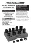
Ball Joint
Super Set
Page
Parts List . . . . . . . . . . . . . . . . . . . . . . . . . . . . 2
Safety Precautions . . . . . . . . . . . . . . . . . . . . 2
Applications :
Press-Fit Ball Joints . . . . . . . . . . . . . . . . . . . . 3
Dana 44 Axles . . . . . . . . . . . . . . . . . . . . . . . . 4
GM 4WD . . . . . . . . . . . . . . . . . . . . . . . . . . . . 5
Ford 2WD Van . . . . . . . . . . . . . . . . . . . . . . . . 6
Dodge / Jeep 4WD . . . . . . . . . . . . . . . . . . . . 7
Honda . . . . . . . . . . . . . . . . . . . . . . . . . . . . . . 8
Form No. 517920
© SPX Corporation Rev. D, 12-21-06
1
Parts List / Safety Precautions
2
3
1
5
4
6
8
9
7
11
10
12
13
14
16
15
17
18
22
20
19
24
21
23
Item
No.
Part No.
No. Req'd
Item
No.
Description
1
7248 1 C-Frame Press (consists of 1 ea.:
37703 forcing screw; 14472 steel ball; 10273 o-ring;
29501 plug; 41925 c-frame)
2
305227 1 Installing Adapter
3
305228 1 Removing Adapter
4
29503 1 Receiving Tube
5
29504 1 Receiving Tube
6
29505 1 Receiving Tube
7
39976 1 Receiving Cup
8
313444 1 Ball Joint Remover
9
222305 1 Receiving Tube
10
222306 1 Receiving Tube
11
314425 1 Receiving Cup
12
314426 1 Removing Adapter
Part No.
No. Req'd
13
222304
14 204508A
15
222307
16
313969
17 38355A
18
314427
19
314392
20
313967
21
38354
22
313970
23
313968
24
314428
514480
1
1
1
1
1
1
1
1
1
1
1
1
1
Description
Receiving Tube
Receiving Cup
Receiving Tube
Installing Cup
Installing Cup
Receiving Cup
Live Center Forcing Screw Plug
Remover Cup
Receiving Cup
Installer
Remover
Installing Adapter
Storage Case (not shown)
Safety Precautions
CAUTION : To prevent personal injury when using these tools,
• Wear eye protection that meets ANSI Z87.1 and OSHA standards.
• Before performing repairs on a vehicle, block the vehicle wheels to prevent
movement of the vehicle.
• Check
2
the final alignment of tooling and components before using the
C-frame to exert pressure.
Shaded areas reflect the last
revisions made to this form.
Press-Fit Ball Joints
Application : Most cars and light trucks that have
press-fit type ball joints.
Installing Adapter
305227
This assembly enables the user to remove and
install ball joints without removing the control arm
from the vehicle.
NOTE: Some cars and light trucks may have the
upper ball joint spot-welded to the control arm.
The weld must be cut before attempting to
remove the ball joint.
Ball Joint
Control
Arm
Receiving Tube
29503
29504
29505
Removal
1. Assemble the ball joint press over the control arm
as shown. Select the correct size receiving tube,
and position it under the vehicle ball joint.
2. Tighten the forcing screw until the receiving tube
contacts the control arm. Check the alignment of
all tooling and components, and continue
tightening the forcing screw until the ball joint is
removed.
Installation
Removing Adapter
305228
Removal
Installing Adapter
305227
1. Clean the control arm and coat the I.D. with a
suitable lubricant.
2. Insert the replacement ball joint as straight as
possible into the vehicle control arm.
3. Assemble the ball joint press components as
shown. Position the receiving tube, and tighten
the forcing screw. Check the alignment of all
tooling and components, and continue tightening
the forcing screw until the ball joint is firmly
seated.
Control
Arm
Receiving Tube
29503
29504
29505
Ball
Joint
Removing Adapter
305228
Installation
3
Dana 44 Axles
Application : Upper and lower ball joints on 1967–current 4WD vehicles with Dana 44 axles.
Removal
1. Remove the knuckle assembly from the vehicle according to the instructions in the service manual.
Note:
• It may be necessary to remove the steering arm before servicing the upper ball joint on left hand knuckle.
• The lower ball joint must be removed before any service can be performed on the upper ball joint.
2. Remove the lower ball joint snap ring.
3. Assemble the ball joint press over the ball joint as shown in Figure 3.
4. Turn the forcing screw until it meets the ball joint. Check the alignment of all components. Tighten the
forcing screw until the ball joint is removed.
5. Repeat Steps 3 & 4 to remove the upper ball joint.
No. 38354
Receiving Cup
No. 38354
Receiving Cup
Lower Ball Joint
Upper Ball Joint
Installation
Note: The lower ball joint must be installed before the upper ball joint.
1. Clean the knuckle and coat it with a suitable lubricant.
2. Assemble the ball joint into the knuckle.
3. Assemble the ball joint press components as shown. Check the alignment of all components. Tighten
the forcing screw until the ball joint is firmly seated.
4. Install the snap ring on the lower ball joint.
5. Repeat Steps 1-3 to install the upper ball joint.
6. Install the knuckle assembly to the vehicle according to the vehicle service manual procedures.
No. 38355A
Installing Cup
No. 38355A
Installing Cup
No. 204508A
Installing
Adapter
No. 204508A
Installing
Adapter
4
Lower Ball Joint
Upper Ball Joint
GM 4WD
Application : 1996–newer GM 4WD 1/2-Ton and 3/4-Ton Pickups, Suburbans, Yukons, Tahoes
1. Position the tools as shown to remove or install the lower ball joint.
Note for Installation: Clean the control arm or knuckle, and coat the I.D. with a suitable lubricant.
2. Tighten the forcing screw until it meets the cup, and check the alignment of all tooling and components.
Continue tightening the forcing screw until the ball joint is removed or installed.
Removing the Lower Ball Joint
No. 7248
C-frame
No. 305227
Installing Adapter
Installing the Lower Ball Joint
No. 204508A
Receiving Cup
No. 7248
C-frame
No. 222307
Receiving Tube
No. 305227
Installing Adapter
5
Ford 2WD Van
Application : Upper and lower ball joints on 1992–97 Ford 3/4-Ton and 1-Ton 2WD Vans
1. Position the tools as shown to remove or install the upper or lower ball joint. Note for Installation: Clean
the control arm or knuckle, and coat the I.D. with a suitable lubricant.
2. Tighten the forcing screw until it meets the cup, and check the alignment of all tooling and components.
Continue tightening the forcing screw until the ball joint is removed or installed.
No. 7248
C-frame
No. 7248
C-frame
No. 305228
Removing
Adapter
No. 305228
Removing
Adapter
No. 222305
Receiving
Tube
No. 204508A
Receiving
Cup
No. 29505
Receiving
Tube
No. 313968
Remover
Removing the Upper Ball Joint
No. 313444
Ball Joint
Remover
Installing the Upper Ball Joint
No. 39976
Receiving
Cup
No. 222304
Receiving
Tube
No. 7248
C-frame
No. 305228
Removing
Adapter
No. 7248
C-frame
6
Removing the Lower Ball Joint
Installing the Lower Ball Joint
Dodge / Jeep 4WD
Application : Upper and lower ball joints on 1993–04 Grand Cherokee; 1994–01 Dodge Ram 4WD 1/2-Ton
Pickup; 1984–89 Jeep Wagoneer, Cherokee, Comanche; 1987–98 Wrangler
1. Position the tools as shown to remove or install the upper or lower ball joint.
Note for Installation: Clean the control arm, and coat the I.D. with a suitable lubricant.
2. Tighten the forcing screw until it meets the cup, and check the alignment of all tooling and components.
Continue tightening the forcing screw until the ball joint is removed or installed.
No. 7248
C-frame
No. 7248
C-frame
No. 313969
Installer Cup
No. 313967
Remover Cup
No. 313968
Remover
No. 313970
Installer
Removing the Upper Ball Joint
Installing the Upper Ball Joint
No. 313968
Remover
No. 313970
Installer
No. 313967
Remover Cup
No. 7248
C-frame
Removing the Lower Ball Joint
No. 313969
Installer Cup
No. 7248
C-frame
Installing the Lower Ball Joint
7
Honda
Application : Lower ball joints on 1986–97 Accord, 1988–00 Civic, 1988–91 CRX, 1993–99 del Sol,
and 1983–98 Prelude
Removal
1. Assemble the ball joint press over the control arm as shown in Figure 1.
2. Tighten the forcing screw until the removing adapter contacts the control arm. Check the alignment of
all tooling and components, and continue tightening the forcing screw until the ball joint is removed.
No. 305227
Installing
Adapter
No. 314427
Receiving
Cup
No. 314425
Receiving
Cup
Control
Arm
Control
Arm
No. 314426
Removing
Adapter
No. 7248
C-frame
Press
No. 7248
C-frame
Press
No. 314426
Removing
Adapter
Figure 1
1990-97 Accord
Figure 1
1986-89 Accord
1988-00 Civic
1988-91 CRX
1993-99 del Sol
1983-98 Prelude
No. 314428
Installing
Adapter
Installation
1. Clean the control arm and coat the I.D. with a
suitable lubricant.
2. Insert the replacement ball joint as straight as
possible into the vehicle control arm.
3. Assemble the ball joint press components as
shown in Figure 2, and tighten the forcing screw.
Check the alignment of all tooling and
components, and continue tightening the forcing
screw until the ball joint is firmly seated.
8
Control
Arm
No. 7248
C-frame
Press
No. 38355A
Receiving
Cup
Figure 2
Honda
Application : Lower ball joints on 1999-2004 Odyssey vans
Removal
No. 313968
Remover
1. Remove the ball joint dust boot.
2. Assemble the ball joint press over the control
arm as shown in Figure 1.
3. Tighten the forcing screw until the removing
adapter contacts the control arm. Check the
alignment of all tooling and components, and
continue tightening the forcing screw until the
ball joint is removed.
Control
Arm
No. 7248
C-frame
Press
No. 313969
Installing
Cup
Figure 1
No. 305227
Installing
Adapter
Installation
1. Clean the control arm and coat the I.D. with a
suitable lubricant.
No. 29505
Receiving
Tube
2. Insert the replacement ball joint as straight as
possible into the vehicle control arm.
3. Assemble the ball joint press components as
shown in Figure 2, and tighten the forcing screw.
Check the alignment of all tooling and
components, and continue tightening the forcing
screw until the ball joint is firmly seated.
4. Install the ball joint dust boot.
Control
Arm
No. 7248
C-frame
Press
Figure 2
9