1
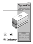
MANUAL AND SERVICE MANUAL
ORLIGNO 100
Content
1. Boiler application . . . . . . . . . . . . . . . . . . . . . . . . . . . . . . . . . . . . . . . . . . . . . . . . . . . . . . . . . . . . . . . . 3
2. Installation . . . . . . . . . . . . . . . . . . . . . . . . . . . . . . . . . . . . . . . . . . . . . . . . . . . . . . . . . . . . . . . . . . . . . . 4
2.1. Ventilation . . . . . . . . . . . . . . . . . . . . . . . . . . . . . . . . . . . . . . . . . . . . . . . . . . . . . . . . . . . . 4
2.2. Supply-air ventilation . . . . . . . . . . . . . . . . . . . . . . . . . . . . . . . . . . . . . . . . . . . . . . . . . . 4
2.3. Exhaust ventilation . . . . . . . . . . . . . . . . . . . . . . . . . . . . . . . . . . . . . . . . . . . . . . . . . . . . 4
2.4. Chimney connection . . . . . . . . . . . . . . . . . . . . . . . . . . . . . . . . . . . . . . . . . . . . . . . . . . . 4
3. Technical data . . . . . . . . . . . . . . . . . . . . . . . . . . . . . . . . . . . . . . . . . . . . . . . . . . . . . . . . . . . . . . . . . . . 5
3.1. Dimensions . . . . . . . . . . . . . . . . . . . . . . . . . . . . . . . . . . . . . . . . . . . . . . . . . . . . . . . . . . . 6
3.2. Boiler construction . . . . . . . . . . . . . . . . . . . . . . . . . . . . . . . . . . . . . . . . . . . . . . . . . . . . 6
3.3. Safety valve connection . . . . . . . . . . . . . . . . . . . . . . . . . . . . . . . . . . . . . . . . . . . . . . . . 7
4. Boiler startup . . . . . . . . . . . . . . . . . . . . . . . . . . . . . . . . . . . . . . . . . . . . . . . . . . . . . . . . . . . . . . . . . . . 9
4.1. Boiler stoking . . . . . . . . . . . . . . . . . . . . . . . . . . . . . . . . . . . . . . . . . . . . . . . . . . . . . . . . 10
4.2. Tarring and condensation . . . . . . . . . . . . . . . . . . . . . . . . . . . . . . . . . . . . . . . . . . . . . 10
5. Maintenance . . . . . . . . . . . . . . . . . . . . . . . . . . . . . . . . . . . . . . . . . . . . . . . . . . . . . . . . . . . . . . . . . . . . 11
2
1. Boiler application
Steel boiler ORLIGNO 100 tested according to EN 303-5 is designed for central heating installations
with maximal temperature on the boiler 90ºC and working pressure 3 bar.
Recommended fuel for boiler: wood, coke, coal and in case of mounting pellet burner – pellets and
oats.
TTENTION!
A
Using fuel different than the recommended not guarantees optimum boiler operation
and achieving parameters featured in technical data. It can also affect durability of the
boiler and its components.
TTENTION!
A
Using fuel different than the recommended is treated as wrong boiler operation and
resultant performance irregularities cannot be reason for complaint.
3
2. Installation
2.1. Boiler-room ventilation
According to european safety regulations each boiler room should have supply-exhaust ventilation
ensuring correct boiler operation and user’s safety . Lack of ventilation or its obstruction is the main
reason of incorrect boiler operation (i.e. boiler cannot reach set temperature).Exhaust ventilation
removes from boiler room used air and harmful gases. Boiler room with natural draught cannot
have installed mechanical ventilation.
2.2. Supply air ventilation
1. Ventilating duct section should have at least 50% area of chimney’s section and not less than
20 x 20 cm. Duct should be placed 1m above the floor.
2. Ventilating duct should have installed device for air flow control; device shouldn’t limit duct
section above 1/5.Ventilating duct should be made of non-inflammable material.
2.3. Exhaust ventilation
1. Exhaust duct should be made of bricks with section of at least 25% of chimney section not less
14 x 14 cm. Inlet hole cannot have any devices that reduce its section. Outlet hole should be
placed close to the ceiling led out 1,5 m above the roof. Ventilating duct should be made of
non-inflammable material.
2. Height of the boiler room min. 2,2 m.
2.4. Chimmey connection.
Chimney ducts should be installed according to binding rules and norms in countries to which
boilers are sold. Part of chimney system connection boiler with chimney is called flue. In order to
lower flow resistance of exhaust gases this part should lead as a straight pipe with, if necessary,
joints up to 45°.
Because of exhaust gases temperature ORLIGNO 100’s need to be connected to heat-resistant.
30 cm above the floor closing door should be installed with tight closing.
Chimney section should be round or close to square shape because of low flow resistance.
Minimal flue diameter should be 160 mm.
Chimney should lead above the roof. Chimney outlet location is dependent on roof slope and its
combustibility.
4
3. ORLIGNO 100 – technical data
Power
wood
Coke/pellets
kW
kW
Boiler class acc. to EN-303-5
14
30/16
3
%
76,5
86
Max working pressure
bar
3
90
Efficiency
coke
pellets
Max temperature
°C
Min. temperature
°C
60
Water capacity
ltr.
60
Weight
kg
305
Loading chamber capacity
ltr.
70
1100
Length
mm
Width
mm
675
Height
mm
1220
mm
300x300
Water outlet
Upper door dimensions
inner thread
inch
5/4”
Return
inner thread
inch
5/4”
Drain valve
inner thread
inch
½”
Cooling coil
inner thread
inch
½”
Min. cooling coil pressure
bar
2
Flue diameter
mm
160
Required chimney draft
Pa
20
%
23/12
Exhaust gases temperature at nominal power
°C
250-280
coke
h
4,5
wood
h
2-2,5
mm
500
6-8
Max. moisture content:
Burning period at nominal power
Fuel parameters
Water resistance
wood/pellets
wood/max length
pellets/ diameter
mm
∆t=20 K
mbar
0,8
∆t=10 K
mbar
3,4
5
3.1. Dimensions
3.2. Boiler construction
6
3.3. Safety valve connection
7
ORLIGNO 100 is equipped with copper cooling coil mounted in boiler body, protecting boiler from
overheating. To one of cooling coil tappings on right side of the boiler one should connect safety
valve.
When temperature increases above 95ºC safety valve opens and lets in cold water through cooling
coil. Water from mains at 10ºC temperature cools down boiler, water from boiler is removed to
drain.
8
4. Boiler startup
Before first startup it is necessary to:
-Check water level in installation, pressure in installation should be 2 bar.
-Check fire-grate location (fire-grate gaps from bottom should be bigger than from top).
-Draft regulator seal with oakum and mount, fit arm and block with screw.
Startup:
-Mount draft regulator horizontally, regulator set on 70°C.
-Open flue flap.
-Put on fire-grate papers and small wood pieces; open bottom door .
-After lightning up put bigger wood logs and create ember layer (close bottom door and
unscrew primary air flap – opening in flap at least 2cm- regulation knob is located on bottom
door.
-After creating ember layer fully load boiler with wood or coke. Put wood logs along
chamber.
-Set chimney draft with flue flap
-Connect draft regulator chain with primary air flap. Burn in boiler up to 70°C then set draft
regulator on 70°C and shorten chain till primary air flap is barely opened. Draft regulator knob
is for temperature change. Marking on regulator is every 10°C.
TTENTION!
A
Before stoking boiler open slowly open upper door to suck out gases.
TTENTION!
A
It is not allowed to open bottom door during boiler burning – glow may fall out.
SECONDARY AIR SETTINGS:
-wood opening ½
-coke opening ¼ .
Troubleshooting
Reason
Activity
Heat exchanger gets dirty to fast
Use good quality wood, moisture content 18-23%.
Smoke leakage
Seal chimney pipe, open more flue flap, check chimney draft
Too high temperature of exhaust
gases
Check fuel moisture content, cannot be too dry.
Check secondary air settings.
Too short burning period
To high exhaust gases temperature: burning period depends on
used fuel and heat demand
9
4.1. Boiler stoking
In order to stoke boiler:
1. Close primary air flap.
2. Open completely flue flap.
3. Open slightly upper door in order to suck out gases through chimney.
4. Open completely upper door and stoke boiler.
5. Close upper door, return to previous setting of flue flap and primary air.
4.2. Tarring and condensation
Lightning up in cold boiler may cause that water precipitated from fuel falls on boiler walls and runs
down to ash chamber. That may look like boiler leakage. It is important to keep boiler temperature
high enough at least 70°C. It is recommended to install four-way mixing valve which protects boiler
from low temperature return below 50°C. Too humid wood also causes that boiler works on low
temperatures, which leads to tarring. In order to avoid problem of tarring and condensation – keep
high boiler temperatures, boiler must be properly sized to heated space to avoid oversizing – boiler
then will work on low temperatures.
1. Boiler ORLIGNO 100
2. Pressure vessel
3. Radiator
4. Safety valve- protection- from verheating
5. Four-way mixing valve
6. Safety group
10
5. Maintenance
dvice:
A
Clean boiler works efficiently. Boiler life is extended.
-Fire-grate and ash clean/remove daily.
-Boiler must be cool during this activities.
-Open upper door and remove cleaning flap.
-Check if heat exchanger surfaces are cleaned, clean with brush.
-Remove ash from bottom chamber ( ashpan may be hot).
-Fit cleaning flap.
-Each 2-4 weeks clean boiler depending on burning intensity.
11
12
INSTRUCTION MANUAL
Contents
1. Basic informations . . . . . . . . . . . . . . . . . . . . . . . . . . . . . . . . . . . . . . . . . . . . . . . . . . . . . . . . . . . . . . 14
1.1. Construction description and burner application . . . . . . . . . . . . . . . . . . . . . . . . . . 14
1.2. Fuel characteristics . . . . . . . . . . . . . . . . . . . . . . . . . . . . . . . . . . . . . . . . . . . . . . . . . . . 15
1.3. Transport and delivery specification . . . . . . . . . . . . . . . . . . . . . . . . . . . . . . . . . . . . 16
2. Burner’s technical data . . . . . . . . . . . . . . . . . . . . . . . . . . . . . . . . . . . . . . . . . . . . . . . . . . . . . . . . . . 17
3. Package . . . . . . . . . . . . . . . . . . . . . . . . . . . . . . . . . . . . . . . . . . . . . . . . . . . . . . . . . . . . . . . . . . . . . . . 18
4. Location and package installation . . . . . . . . . . . . . . . . . . . . . . . . . . . . . . . . . . . . . . . . . . . . . . . . . 19
4.1. Rules, norms, recommendations . . . . . . . . . . . . . . . . . . . . . . . . . . . . . . . . . . . . . . . 19
4.2. Boiler room recommendation . . . . . . . . . . . . . . . . . . . . . . . . . . . . . . . . . . . . . . . . . 20
4.3. Ventilation . . . . . . . . . . . . . . . . . . . . . . . . . . . . . . . . . . . . . . . . . . . . . . . . . . . . . . . . . . . 20
4.4. Safe distance to inflammable substances . . . . . . . . . . . . . . . . . . . . . . . . . . . . . . . 20
5. Putting into operation . . . . . . . . . . . . . . . . . . . . . . . . . . . . . . . . . . . . . . . . . . . . . . . . . . . . . . . . . . . 22
5.1. Burner start . . . . . . . . . . . . . . . . . . . . . . . . . . . . . . . . . . . . . . . . . . . . . . . . . . . . . . . . . . 22
5.2. Burner’s assembly to ORLIGNO 100 . . . . . . . . . . . . . . . . . . . . . . . . . . . . . . . . . . . . 22
5.3. Adjustment of ORLIGNO 100 to work with pellet burner . . . . . . . . . . . . . . . . . . . 22
5.4. Tank assembly . . . . . . . . . . . . . . . . . . . . . . . . . . . . . . . . . . . . . . . . . . . . . . . . . . . . . . . 24
5.5. Before starting of the burner it is necessary . . . . . . . . . . . . . . . . . . . . . . . . . . . . . . 25
6. Burner’s maintenance . . . . . . . . . . . . . . . . . . . . . . . . . . . . . . . . . . . . . . . . . . . . . . . . . . . . . . . . . . . 26
7. Troubleshooting . . . . . . . . . . . . . . . . . . . . . . . . . . . . . . . . . . . . . . . . . . . . . . . . . . . . . . . . . . . . . . . . 27
II. Instrukcja regulatora . . . . . . . . . . . . . . . . . . . . . . . . . . . . . . . . . . . . . . . . . . . . . . . . . . . . . . . . . . . . . 28
8. Main functions of the controller. . . . . . . . . . . . . . . . . . . . . . . . . . . . . . . . . . . . . . . . . . . . . . . . . . . 28
9. Graphic display . . . . . . . . . . . . . . . . . . . . . . . . . . . . . . . . . . . . . . . . . . . . . . . . . . . . . . . . . . . . . . . . 29
10. Service. . . . . . . . . . . . . . . . . . . . . . . . . . . . . . . . . . . . . . . . . . . . . . . . . . . . . . . . . . . . . . . . . . . . . . . . 30
11. Simple menu . . . . . . . . . . . . . . . . . . . . . . . . . . . . . . . . . . . . . . . . . . . . . . . . . . . . . . . . . . . . . . . . . . 33
12. Main menu . . . . . . . . . . . . . . . . . . . . . . . . . . . . . . . . . . . . . . . . . . . . . . . . . . . . . . . . . . . . . . . . . . . . 35
13. Heating . . . . . . . . . . . . . . . . . . . . . . . . . . . . . . . . . . . . . . . . . . . . . . . . . . . . . . . . . . . . . . . . . . . . . . . 36
14. Hot domestic water . . . . . . . . . . . . . . . . . . . . . . . . . . . . . . . . . . . . . . . . . . . . . . . . . . . . . . . . . . . . . 38
15. Water tank . . . . . . . . . . . . . . . . . . . . . . . . . . . . . . . . . . . . . . . . . . . . . . . . . . . . . . . . . . . . . . . . . . . . . 40
16. Boiler. . . . . . . . . . . . . . . . . . . . . . . . . . . . . . . . . . . . . . . . . . . . . . . . . . . . . . . . . . . . . . . . . . . . . . . . . . 40
17. Settings . . . . . . . . . . . . . . . . . . . . . . . . . . . . . . . . . . . . . . . . . . . . . . . . . . . . . . . . . . . . . . . . . . . . . . . 41
18. Burner . . . . . . . . . . . . . . . . . . . . . . . . . . . . . . . . . . . . . . . . . . . . . . . . . . . . . . . . . . . . . . . . . . . . . . . . . 41
19. Alarms . . . . . . . . . . . . . . . . . . . . . . . . . . . . . . . . . . . . . . . . . . . . . . . . . . . . . . . . . . . . . . . . . . . . . . . . 43
20 Electric installation . . . . . . . . . . . . . . . . . . . . . . . . . . . . . . . . . . . . . . . . . . . . . . . . . . . . . . . . . . . . . . 44
13
1. Basic informations
1.1. Construction description and burner application
Self- cleaning burner is a new look into the automatic burning of solid fuels in Europe – pellets of
6-8 mm of diameter or as a option oats with maintaining low emissions, complying with European
norms.
Burner doesn’t have any drawbacks of chute burners –gravitational, in which ash and sinter have
to be removed manually.
Main burner advantage is its simple service: just fill in hopper with pellets and press START button.
Reports are shown on big graphic display. Within few minutes burner will automatically select work
parameters, maintain constant room temperature and hot utility water.
Burner’s features:
-automatic burner’s start
-automatic modulation
-flame control through photo-cell
-low heat inertness during start and stop
-low electric energy consumption
-possibility to control 16 heating circuits (radiators and underfloor heating or hot utility water)
– option
-control of burner’s temperature
-three phases of lightning up eliminate risk of explosions
-AUTOSTART function after power failure – memory of last settings
-separation of primary and secondary air – emissions on the same level as in gas and oil
burners
-efficiency > 94,5%
-soot = 0
-self-cleaning function, automatically removes ash from the burner’s grate
-oats –burner’s construction enables to burn grain (oats) – option
2 years of warranty for appliance durability enables to decrease exploitation and service
costs.
Burner’s regulator can control:
- boiler pump
-1-16 heating circuits (radiators or underfloor heating) controlled according to outside
temperature
-room’s temperature
14
Useful functions of controller:
You don’t have to keep in mind about next boiler service – it is shown on the display
Statistics – function enables to preview
-minimal, maximal and average burner’s power
-fuel usage: minimal, maximal and average.
Temperature’s parameters are shown as a digits and charts on big graphic display
1.2. Fuel characteristics
a) Pellet granulate made according to DIN 51731
-granulate 5-8 mm
-recommended calorific value 17500-19500 kJ/kg
-ash content 1,5%
-max moisture content 12%
-density 1-1,4 kg/dm³
b) Oats
- moisture content <15%
TTENTION!
A
It is recommended to use fuel from reliable sources. Fuel should have appropriate
humidity and low content of small fractions. It is necessary pay attention especially
to mechanical pollution ( stones), which worsen burning process and may lead to
burner’s failure.
Eko-Vimar Orlański sp. z.o.o. is not responsible for appliance failure or improper burning process
when using inappropriate fuel.
15
1.3. Transport and delivery specification
Burner during transport should be secured with straps against leaning and movement.
Burner need to be stored in roofed and dry place.
Burner is delivered in separate boxes wrapped in foil. Boxes contains: pellet tank with lid, fuel
feeder, burner with controller and elastic feeding pipe. Before installation it is recommended to
check delivery completeness and its condition.
16
2. Burner’s technical data
Parameter
Pellet power range
Oats power range*
Efficiency
CO emission
Weight
Feeder length standard
Feeder length option
Fuel
Fuel diameter
Fuel (option) humidity<15%
Voltage
Power consumption
Protection level
Tank dimensions
Capacity
SI
kW
kW
%
ppm
kg
m
m
mm
V
W
mm
L
16 kW
4 – 16
3,6 – 14,4
>94,5
<200
14
1,3 – 1,6
2.0;2.5;3.0
pelety
6–8
owies
230
30
IP40
600x600x1400
305
TTENTION!
A
Producer reserves the right for construction and documentation changes in order to
modernize the boiler.
1. Boiler
2. Burner
3. Fuel tank
4. Feed system
Pic.1. Basic package elements.
17
1. Burner’s body
2. Grate
3. Fan
4. Feeder casing ( worm+
igniter)
5. Drive plate
6. Plate for electric
connections
7. Sealant
8. Motoreducer
9. Burner’s casing
Pic.2. Burner construction
3. Package
Standard package:
18
-burner
-controller
-fuel feeder
-tank
-manual
-4 refractory bricks
-Sensor sleeve ½”
4. Location and package installation
4.1. Rules, norms, recommendations
Boiler room should comply with construction law valid in country where boiler is installed.
Pic.3. Package layout.
19
4.2. Boiler room recommendation
-Package ( boiler, burner, tank, feeder) should be placed in separate room, centrally to heated
rooms
-Front door should open outside and must be made of nonflammable materials, with 0,8
width
-Floor should be made of nonflammable materials or covered with 0,7 mm steel plate at
minimum 0,5 m distance to door edges. Boiler should be located on a nonflammable
foundation, lifted 0,05 m above floor level
-Boiler room should have artificial lightning but natural light is also recommended
-Distance to walls in boiler room should allow for easy access to all sides of the boiler
-Minimal distance from front side of the boiler to opposite wall should be 1m
-Minimal height of the boiler room: at least 2,2 m; in existing building it is allowed 1,9 m with
assured supply-exhaust ventilation.
-It is forbidden to install boiler and burner in damp rooms or with elevated humidity. Corrosion
process may in short time damage the boiler and burner.
4.3. Ventilation
-Boiler room should have 200 cm² supply-air duct
-Exhaust duct should have at least 14x14 cm section with inlet hole under boiler room ceiling
that should lead above roof and be placed near chimney.
-Ventilation ducts should be made of nonflammable materials.
-It is forbidden to install mechanical ventilation
TTENTION!
A
High risk of carbon monoxide poisoning exists if boiler is located in a room with
insufficient access to fresh air.
4.4. Safe distance to inflammable substances
-During installation and exploitation it is advisable to maintain safe distance of 200 mm from
inflammable substances
-For inflammable substances with C3 grade of combustibility which rapidly and easy burn (ex.
paper, cardboard, wood, plastic) distance is minimum 400 mm;
-If combustibility grade is unknown safe distance should be doubled.
20
Combustibility grade of building
products
Building products
A – non-burning
sandstone, concrete, bricks, fire plaster, Mortar,
tile, granite
B - hard burning
cement board, fiberglass, mineral insulation
C1- hard burning
beech tree, oak tree, plywood
C2 – middle burning
pine, larch, spruce tree, cork, rubber floor cover
C3 – easy burning
tarmac plywood, celuloids, polyurethane,
Polystyrene, polyethylene, plastic
User please remember:
-Only adult person acquainted with this manual may operate the burner It is forbidden for kids
to stay in close distance to burner without presence of adult person.
-If inflammable gases penetrate boiler room during activities (varnishing, gluing) it is
recommended to turn off the burner.
-It is forbidden to use inflammable substances for lightning up the burner, burner will light up
automatically.
-High risk of fire exist when using open fire or inflammable substances close to installed boiler
package.
-Burner should be turned off during maintenance (position OFF.
-Pay attention on hot burner’s surfaces – risk of burn.
-It is forbidden to lay inflammable items on the burner or nearby.
-All defects should be removed at once.
-After heating season it is recommended to clean the burner and pellet tank thoroughly.
-Oversee the burner during power failure
-It is forbidden to manipulate with any electric parts or interfere in burner’s construction.
21
5. Putting into operation
5.1. Burner start
First startup of the burner must be done by authorized company trained by manufacturer with valid
certificate of authorized serviceman issued by Eko-Vimar Orlanski ltd.
5.2. Burner’s assembly to ORLIGNO 100
1. Remove the screws (1) fastened to burner’s casing (pic.4) and take off casing (2)
2. T
ake off ORLIGNO 100 bottom door
3. Fix adapter (3) in bottom’s door place (pic.5)
4. F
ix burner (4) in adapter (3) screwing it with two bolts (5)
5. Mount burner’s casing (2) with two screws (1)
6. S
lide feeder’s pipe (6) in to fixing pipe (7) (pic.6)
7. Fit flexible pipe (8) on feeder’s pipe (6) and secure with band clip (9)
8. Fit flexible pipe (8) on burner’s pipe (10) and secure with band clip (9)
5.3. Adjustment of ORLIGNO 100 to work with pellet burner
1. Remove iron-cast grate from boiler.
2. P
lace two refractory bricks on each of two supports above support for iron-cast grate.
Pic.4. Disassembly of burner’s casing.
22
Pic.5. Burner assembly.
Pic.6. Feeder assembly
23
5.4. Tank assembly
24
5.5. Before starting of the burner it is necessary:
1. Check installation condition.
2. F
ill in pellet to the tank, cover with lid
3. Check if fuel contains any unwanted elements ( rocks, metal elements)
4. S
crew in sensor’s sleeve in one of two probes on the right side of boiler behind safety coil
5. Put the boiler sensor in to the sleeve
Pellet*
30% of power
100% of power
Feed time
1,5
5
Max air
8
13
OATS**
Feed time
2
7
Max air
9
14
8. Feed fuel from tank till it show up in flexible pipe.
9. T
urn off fuel feed and hold ON button.
10. W
hen changing fuel ex. on oats; it is necessary:
-turn off boiler
-wait till boiler cool down
-remove pellet grate and clean surface
-put oats grate
-set feed time and max air amount acc. to chart
11. B
urner maintenance after heating season:
-turn off and disconnect from power supply
-clean thoroughly
-remove pellet from tank
25
6. Burner’s maintenance
TTENTION!
A
It is necessary to put out, cool down and disconnect burner from power supply when
servicing.
Pay attention on hot burner’s surfaces – risk of burn.
In order to keep high efficiency of burner it is recommended to clean and service it
systematically. Remove soot and ash from burner’s grate.
TTENTION!
A
Much more ash is created during oats burning than pellets.
Cleaning activities:
1. Turn off the boiler (wait till burner completely put out), disconnect boiler from power supply and wait till
boiler cool down.
2. D
isconnect burner form boiler and power supply.
3. Remove grate from burner and clean it ( check permeability of air holes) Clean burner’s casing
(pic.7)
Pic.7. Burner maintenance.
26
7. Troubleshooting
Type of defect
Possible cause of defect
Suggested repair
One of controller’s
button doesn’t
work
Display malfunction
Display repair
Automatic lightning
up Doesn’t work
Wrong connection of igniter or
photo-cell
Check plug and wires connections of igniter and
photo-cell
Clogged outlet hole of hot air
Clean heater hole
Very damp fuel
Change or dry fuel
Damaged igniter
Replace igniter
Damaged photo-cell
Replace photo-cell
Smoke from door
or burner
Water in boiler
Boiler cannot reach
set temperature
Lack of chimney draft
Clogged chimney
Clogged heat exchanger
Clean heat exchanger
Damaged sealant (rope)
Replace sealant (rope)
Lack of chimney draft
Improper chimney installation
Very damp fuel
Change or dry fuel
Leaky heat exchanger
To check heat exchanger, turn off boiler on 8 hours,
remove water, when water is still in boiler – call
service
Improperly selected boiler for
heating space
Check if boiler is properly selected
Wrongly located sensor of return
water
Check sensor location
Sensor malfunction
Check sensors
Set low boiler power
Check feed time and fan power
27
8. Main functions of the controller.
8.1. Front panel
Graphic display (2.1.3)
Buttons (2.1.2)
Status diode (2.1.1)
8.2. Status diode
Lightning description
Green- continuous light
Green – pulsate
Orange – continuous light
Orange – pulsate
Red – continuous light
Red – pulsate
28
Meaning
Controller off
Controller on, burner off
Controller on, burner on
Burner work
Alarm – to confirm
Alarm active
8.3. Buttons
Function
Button
Return, Esc
Return in menu to previous level, cancellation of
parameter’s change. After pressing button > 3 sec –
change of controller’s status ON/OFF
Menu moving, decrease parameter’s value On main display
entering to simple menu
Arrow down
Shows navigational informations and description of
parameters
Info
Menu moving, increase parameter’s value
On main display entering to simple menu
Arrow up
Enter the menu. Confirmation of edited parameter
Alarm confirmation
Enter
9. Graphic display
9.1. Graphic display
grate status
weekday
time
set temperature
actual temperature
object symbol (boiler)
processor’s temperature
number of unconfirmed alarms
heating program ( time program, permanent, off)
h.d.w. program (time program, permanent, off)
grate program (OFF/ON)
controller’s status (OFF/ON)
29
9.2. Grate statuses
Status
OFF
Cleaning
Lightning up
Kindling
Power 1
Power 2
Modulation
Extinguishing
Stop
Description
Burner doesn’t work. Work approval off.
Burner cleaning with strong stream of air.
Fuel lightning up. Initial fuel feeding, Heater and fan
are on.
After flame detection, additional fuel feeding and fan
power increase for better grate kindling.
Burner works with first power.
Burner works with second power.
Burner works with modulated power.
Grate extinguishing. Feeder and fan work till flame die
out.
Burner doesn’t work. Required boiler’s temperature
reached.
10. Service
10.1. Menu navigation
Controller contains two types of menu: simple and main menu.
Simple menu – enables to access basic functions of the controller. To enter simple menu press
button “arrow up” or “arrow down” on main display. Simple menu description chapter 4.
Main menu – enables to access all functions of the controller ( monitoring of status, changes and
service settings ). To enter main menu press “Enter” on main display. Main menu description
chapter 5.
TTENTION!
A
Service menu is only for qualified staff. Any settings’ changes may lead to incorrect
system operation.
10.2. Start of the controller ON
In order to start the controller (mode ON) press for 3 sec “Return, Esc” on main display, when it is
in OFF mode.
30
10.3. Shutdown of the controller OFF
In order to turn the controller off (mode OFF) press for 3 sec Return, Esc” on main display, when it
is in ON mode.
ATTENTION!
After controller shutdown depending on its previous status, burner may still work
(extinguishing ), it’s not advisable to disrupt this process. If controller will be
disconnected from main power, please wait till burner status is on OFF mode.
10.4. Time programs
Controller is equipped with clock and calendar. Thanks to that it is possible to program work of
individual parts of heating system depending on current time and weekday. Date and time aren’t
deleted during power outage because controller contains battery, which needs to be replaced
every 2 years.
Programming takes place in menu of given heating circuit ( ex. hot domestic water, heating, water
tank) and for each element proceeds in the same way.
Weekday choice. After entering in menu “ Time program”, weekday pulsates, with arrow buttons
choose day for setting or just to check program settings.
Programming. After choosing weekday and confirming with “Enter” button; current programmed
hour starts to pulsate, next to displayed hour, icon with chosen time zone is shown (sun symbol
stands for comfort temperature, moon symbol – economic temperature). To move to next hour
press “arrow down” button ( comfort temperature) or “arrow up” (economic temperature). If all
day is programmed press “enter”. After confirmation of changes (or cancellation) weekday starts
to pulsate.
grate status
day
arrow up – set comfort temperature
arrow down – set economic temperature
chosen temperature (economic)
actual set temperature
Economic temperature 00:00 - 6:00
Comfort temperature 6:00 - 9:00
Economic temperature 9:00 - 18:00
Comfort temperature 18:00 - 24:00
31
TTENTION!
A
Values of economic and comfort temperatures are set in SETTINGS menu and may
differ for each of the heating circuits. In order to activate time program activate it in
SETTINGS menu.
10.5. Service password
Access to service parameters is protected with password. After writing correct password access is
cleared. Access is denied after 10 minutes without pressing the buttons.
Service password: it is a set temperature in BOILER/SETTINGS menu and 3 letters “EST”
Example: If set temperature in BOILER/SETTINGS menu is 60°C then password is: „60EST”.
TTENTION!
A
Service menu is only for qualified staff. Any settings’ changes may lead to incorrect
system operation.
32
11. Simple menu
11.1. Simple menu’s displays
Display
Description
Shows current boiler temperature (large type) and
programmed temperature (small type). After pressing
“Enter” button: set desired boiler’s temperature
Shows current h.d.w. temperature (large type) and
programmed temperature (small type). After pressing
“Enter” button: set desired h.d.w. temperature
Heats once h.d.w. till reaching comfort temperature no
matter of program.
H.d.w. program no. 1:
a. time program – according to programmed time- intervals
b. permanent – no matter of time-intervals comfort
temperature is kept
c. off – heating is turned off.
33
Shows current room temperature in room no.1 (large type)
and set value (small type). After pressing “Enter”, set desired
room temperature
Circuit heating program no. 1:
a. time program – according to programmed time- intervals
b. permanent – no matter of time-intervals comfort
temperature is kept
c. off – heating is turned off
Burner work: ON/OFF. When burner is OFF, controller
controls heating system, but doesn’t start the burner.
Manual start of feeder from pellet tank. Function useful
after fuel runs out. After filling the tank with fuel activate
FEED THE FUEL function, till the moment when fuel will
be on the burner.
34
12. Main menu
13 Heating
strona 36
14 H.d.w
page 38
15 Water tank
page 40
16 Boiler
page 40
17 Settings
page 41
18 Burner
page 41
19 Alarms
page 43
35
13. Heating
13.1. Circuit selection
Enables to choose number of heating system circuit. Selection of circuit: “arrow down/up”.
13.2. Status
Enables to monitor status of central heating.
Circuit number
Name of circuit
Measured temperature/ programmed in room
Measured temperature/ programmed in radiators
Outside measured temperature
Valve work time (sec)
Programmed temperature at source (°C)
Valve work signalling
Pump work signalling
36
13.3. Settings
Description of functions in submenu SETTINGS.
Function
Comfort temperature
Program
Economic temperature
Description
Programmed temperature in room during heating.
Programs:
a. time program – according to programmed time- intervals
b. permanent – no matter of time-intervals comfort
temperature is kept
c. off – heating is turned off
d. e
conomic – during all period economic temperature in room
is kept
Programmed temperature in room after heating period
13.4. Time program
It is for time program configuration that controls central heating.
Settings description of time program can be found in chapter 3.4
13.5. Service
TTENTION!
A
Service menu is only for qualified staff. Any settings’ changes may lead to incorrect
system operation.
Description of functions in submenu SERVICE.
Function
Temp. MIN pump comf.
Temp. MIN pump. econ.
Description
Minimal calculated central heating temperature, at which
pump is ON during comfort period.
Minimal calculated central heating temperature, at which
pump is on during economic period
Source
Max. temperature
Determines source of energy for central heating
Maximal calculated temperature for central heating
Mixing valve time
H.d.w. priority
Pump test
Time when mixing valve is fully opened
H.d.w. priority for given central heating circuit; during h.d.w.
heating, central heating pump doesn’t work
Starts circulation pump regardless of outside conditions.
Mixing valve test
Circuit name
Starts mixing valve actuator regardless of outside conditions.
Gives the name for central heating circuit.
37
14. Hot domestic water
14.1. Circuit selection
Enables to choose number for h.d.w. circuit.
14.2. Status
Enables to monitor status of h.d.w.
Circuit number
Circuit name
Measured temperature/ programmed for h.d.w.
Source programmed temperature (°C)
Pump work signalling
38
14.3. Settings
Description of functions in submenu SETTINGS
Function
Comfort temperature
Program
Heat now
Description
Programmed temperature of h.d.w. during heating period
Programs:
a. time program – according to programmed time- intervals
b. permanent – no matter of time-intervals comfort
temperature is kept
c. off – heating is turned off
Hysteresis
Heats once h.d.w. up to comfort temperature regardless of
program
Decrease of temperature value for h.d.w.
Economic temperature
Programmed h.d.w. temperature after heating period.
14.4. Time program
It is for time program configuration of h.d.w.
Settings description of time program can be found in chapter 3.4
14.5. Service
TTENTION!
A
Service menu is only for qualified staff. Any settings’ changes may lead to incorrect
system operation.
Description of functions in submenu SERVICE:
Function
Source delta
Source
Max. temperature
Delta MIN temp.
Description
Source temperature increase in relation to programmed
h.d.w temperature during heating.
Determines source of energy for h.d.w.
Pump test
Maximal h.d.w. temperature
Minimal temperature difference between source and h.d.w,
at which pumps work
Starts pump regardless of other conditions.
Circuit name
Gives the name for h.d.w. circuit
39
15. Water tank
15.1. Service
ATTENTION!
Service menu is only for qualified staff. Any settings’ changes may lead to incorrect
system operation.
16. Boiler
16.1. Status
Boiler work statistics during last 24h. Chart shows boiler’s temperature and burner power.
16.2. Settings
Description of functions in submenu SETTINGS.
Function
Programmed boiler’s
temperature
Description
Heat medium temperature in the boiler kept by the
controller.
16.3. Service
ATTENTION!
Service menu is only for qualified staff. Any settings’ changes may lead to incorrect
system operation.
40
Description of functions in submenu SERVICE:
Function
Pumps MIN temp
Work mode
Hysteresis
Description
Temperature above which controller may turn on the
pumps
Boiler’s work mode:
a. auto – temperature set automatically
b. continuous – temperature is kept continuously
Temperature’s value that needs to decrease to start the
burner.
17. Settings
17.1. Date and time
Enables to set the date and controller’s time.
17.2. Language
Enables to choose controller’s language in menu.
17.3. Restore factory settings
Selecting this option enables to cancel all current controller’s settings and restore factory
settings.
18. Burner
18.1. Status
Animation showing work of burner’s appliances.
41
18.2. Settings
Description of functions in submenu SETTINGS.
Function
Description
Feed the fuel
Starts feeder regardless of other functions.
Burner’s work
Burner’s work approval.
Type of fuel
Determines type of burned fuel.
18.3. Service
TTENTION!
A
Service menu is only for qualified staff. Any settings’ changes may lead to incorrect
system operation.
Function
Description of functions in submenu SERVICE
Air MIN
Minimal air amount during modulation or at power no. 1
Air MAX
Maximal air amount during modulation or at power no. 2
Feeding MAX
MIN power
Minimal burner’s power during modulation.
Maximal burner’s power during modulation.
MAX power
Maximal burner power during modulation.
Modulation type
Test of igniter
Method of burner’s work, modulated power or 2 levels of
power
Brightness in burner, above which controller recognizes
flame
Starts igniter for test.
Test of burner’s feeder
Starts feeder for test.
Test of fuel’s feeder
Test of fan
Starts feeder for test.
Starts fan for test.
Photo threshold
42
19. Alarms
Menu contains history of maximum 20 alarms, that occured during controller’s work. Meanings of
code alarms is shown below:
Alarm codes and their meaning.
Code
Short description
Description
1
Processor’s overheating
Controller’s processor has been overheated. Improper
controller placement may be one of the reasons.
Controller detected lack of flame in burner. Lack of fuel
or flame gone out may be one of the reasons.
Burner’s temperature has exceeded maximum value
2
Lack of flame/fuel
3
Burner’s overheating
4
Boiler’s sensor short circuit
5
Boiler’s sensor break
6
Burner’s sensor short circuit
7
Gape of burner’s sensor
8
Boiler’s overheating
Controller detected short circuit. Damaged sensor or
connecting wire may be one of the reasons.
Controller detected gape of boiler sensor. Damaged
sensor or conecting wire may be one of the reasons.
Controller detected gape of sensor. Damaged sensor or
connecting wire may be one of the reasons.
Controller detected gape of sensor. Damaged sensor or
connecting wire may be one of the reasons
Boiler’s temperature has exceeded maximum value
9
Processor reset
Possible controller’s damage! Lack of power supply
43
20. Electric installation
20.1. Overall requirements
Before use of this controller; it is necessary to thoroughly read instruction manual.
Person responsible for controller’s installation should have technical experience. Connections
made of copper should be adjusted to operate at temperatures of 75°C.
All electric connections should comply with electric scheme enclosed in this manual and national
or local rules concerning electric installations
TTENTION!
A
Appliance should be connected to separate electric circuit equipped with properly
selected RCD (residual current device) and MCB ( miniature circuit breaker).
20.2. Location
Appliance is intended for use in confined premises.
Assembly location must be free from dampness and inflammable, fumes that cause corrosion.
Appliance assembly cannot be done close to any high-power, appliances, industrial equipment or
welding equipment.
Ambient temperature around assembly place cannot exceed 60°C and should not be lower than
0°C. Humidity should be in range 5-95%.
20.3. Connection
It is necessary to connect to boiler sensor and other executiue elements if needed. Picture shows
connection diagram of appliances table shows description of inputs and outputs.
TTENTION!
A
It is not allowed to connect (PE) safety wire with zero(N).
44
TTENTION!
A
Connection works should be made when controller is disconnected from power.
Only authorized person is allowed to do electrical connections with necessary
qualifications.
BACK VIEW OF CONTROLLER
FILTER
Output description
Foto
Tkotła
Tpalnik
Tc.w.u.
Tpokój
GND
Pcwu
Zapalarka
Pco
Dmuchawa
Pod.zas.
Pod.pal
N
N1
PE
Description
Brightness sensor in burner
Boiler sensor
Burner sensor
Hot domestic water sensor
Room sensor
Ground for sensor connection
Hot domestic water pump
Burner's igniter
Central heating pump
Burner's fan
Pellet tank feeder
Burner's feeder
Neutral constant
Neutral separable
Protective
45
20.4. Technical data
PARAMETER
Power supply
Power consumpion
Outputs capacity:
Central heating pump
Hot domestic water pump
Igniter
Fan
Burner's feeder
Pellet tank feeder
Measurement accuracy
Sensors
Outside temperature
Humidity
Software class
46
VALUE
~230V/50Hz ±10%
<6VA
100W
100W
400W
150W
150W
150W
±4ºC
NTC 10kΩ
B
=3877K±0,75%
25/85
VISHAY BCcomponents
0-60ºC
5-95% without condensation
A
47
EKO-VIMAR ORLAŃSKI Sp. z o.o.
48-385 Otmuchów, ul. Nyska 17b
POLSKA / woj. opolskie
T +48 77 400 55 80-81, 400 55 91
F +48 77 439 05 03, 400 55 96
E [email protected]
www.orlanski.pl