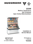
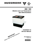
1
® Medium Temperature Meat, Delicatessen, Dairy and Produce Merchandisers Installation & Service Manual Shipped With Case Data Sheets IMPORTANT Keep in store for future reference! MANUAL- I/O EXCEL MEDIUM TEMPERATURE P/N 0463880_P Excel Series August 2014 Spanish 0486356 French 0521930 P/N 0463880_P iii TABLE OF CONTENTS INSTALLATION TOOL LIST . . . . . . . . . . . . . . . . . iv INSTALLATION NSF Certification. . . . . . . . . . . . . . . . . . . . . . . . . . . . 1-1 Location. . . . . . . . . . . . . . . . . . . . . . . . . . . . . . . . . . . 1-1 Shipping Damage. . . . . . . . . . . . . . . . . . . . . . . . . . . . 1-2 REFRIGERATION / ELECTRICAL Refrigerant. . . . . . . . . . . . . . . . . . . . . . . . . . . . . . . . . 2-1 Refrigerant Piping . . . . . . . . . . . . . . . . . . . . . . . . . . . 2-1 Standard Connection Location. . . . . . . . . . . . . . . . . . . . . 2-1 Refrigeration Shroud. . . . . . . . . . . . . . . . . . . . . . . . . . . . . 2-2 Optional Internal Top Piping Location . . . . . . . . . . . . . . 2-2 Apparent Loss or Damage . . . . . . . . . . . . . . . . . . . . . . . . 1-2 Multiplexing. . . . . . . . . . . . . . . . . . . . . . . . . . . . . . . . . . . . 2-3 Concealed Loss or Damage . . . . . . . . . . . . . . . . . . . . . . . 1-2 Line Sizing . . . . . . . . . . . . . . . . . . . . . . . . . . . . . . . . . . . . . 2-3 Unloading. . . . . . . . . . . . . . . . . . . . . . . . . . . . . . . . . . Serial Plate Location . . . . . . . . . . . . . . . . . . . . . . . . . Exterior Loading . . . . . . . . . . . . . . . . . . . . . . . . . . . . Merchandisers Shipped with End Installed. . . . . . . . Shipping Braces . . . . . . . . . . . . . . . . . . . . . . . . . . . . . Shipping Rider. . . . . . . . . . . . . . . . . . . . . . . . . . . . . . Merchandiser Leveling. . . . . . . . . . . . . . . . . . . . . . . . Joining Instructions. . . . . . . . . . . . . . . . . . . . . . . . . . 1-2 1-2 1-2 1-2 1-2 1-3 1-3 1-5 Preparation. . . . . . . . . . . . . . . . . . . . . . . . . . . . . . . . . . . . . 1-5 Apply Gaskets . . . . . . . . . . . . . . . . . . . . . . . . . . . . . . . . . . 1-5 Align End Frames . . . . . . . . . . . . . . . . . . . . . . . . . . . . . . . 1-8 Fasten End Frames . . . . . . . . . . . . . . . . . . . . . . . . . . . . . 1-13 Oil Traps. . . . . . . . . . . . . . . . . . . . . . . . . . . . . . . . . . . . . . . 2-3 Pressure Drop. . . . . . . . . . . . . . . . . . . . . . . . . . . . . . . . . . . 2-3 Insulation. . . . . . . . . . . . . . . . . . . . . . . . . . . . . . . . . . Suction Line. . . . . . . . . . . . . . . . . . . . . . . . . . . . . . . . Liquid Line. . . . . . . . . . . . . . . . . . . . . . . . . . . . . . . . . Refrigeration Thermostat . . . . . . . . . . . . . . . . . . . . . Defrost Termination Thermostat . . . . . . . . . . . . . . . Defrost Sequences . . . . . . . . . . . . . . . . . . . . . . . . . . . Merchandiser Electrical Data . . . . . . . . . . . . . . . . . . Electrical Connections. . . . . . . . . . . . . . . . . . . . . . . . Field Wiring. . . . . . . . . . . . . . . . . . . . . . . . . . . . . . . . Identification of Wiring. . . . . . . . . . . . . . . . . . . . . . . 2-3 2-4 2-4 2-5 2-5 2-5 2-6 2-6 2-6 2-6 Fasten Canopies . . . . . . . . . . . . . . . . . . . . . . . . . . . . . . . 1-13 Tighten End Frames . . . . . . . . . . . . . . . . . . . . . . . . . . . . 1-14 Seal Merchandiser . . . . . . . . . . . . . . . . . . . . . . . . . . . . . . 1-14 Install Splashguard Brackets. . . . . . . . . . . . . . . . . . Offsetting Bumper . . . . . . . . . . . . . . . . . . . . . . . . . . Installing Partitions . . . . . . . . . . . . . . . . . . . . . . . . . Installing End Assemblies . . . . . . . . . . . . . . . . . . . . Front Glass Adjustment. . . . . . . . . . . . . . . . . . . . . . Optional Front Rail Light. . . . . . . . . . . . . . . . . . . . 1-15 1-15 1-17 1-17 1-22 1-23 DRIP PIPING AND SPLASHGUARDS Waste Outlet and Water Seal. . . . . . . . . . . . . . . . . . . 3-1 Installing Drip Piping. . . . . . . . . . . . . . . . . . . . . . . . . 3-1 Optional Drip Piping Arrangements. . . . . . . . . . . . . . . . . 3-2 Installing Splashguards . . . . . . . . . . . . . . . . . . . . . . . 3-3 IMPORTANT KEEP IN STORE FOR FUTURE REFERENCE Quality that sets industry standards! 12999 St. Charles Rock Road • Bridgeton, MO 63044-2483 U.S. & Canada 1-800-922-1919 • Mexico 1-800-890-2900 www.hussmann.com © 2014 Hussmann Corporation (Continued) iv START UP / OPERATION Start up. . . . . . . . . . . . . . . . . . . . . . . . . . . . . . . . . . . . Stocking . . . . . . . . . . . . . . . . . . . . . . . . . . . . . . . . . . . Load Limits . . . . . . . . . . . . . . . . . . . . . . . . . . . . . . . . Install Shelves . . . . . . . . . . . . . . . . . . . . . . . . . . . . . . Multi-deck Shelf Configuration. . . . . . . . . . . . . . . . . Shelf Maximum Weight Limits. . . . . . . . . . . . . . . . . Multi-deck Shelf Alignment. . . . . . . . . . . . . . . . . . . . LED Light Fixtures . . . . . . . . . . . . . . . . . . . . . . . . . . Fluorescent Fixtures . . . . . . . . . . . . . . . . . . . . . . . . . Installing Lighted Shelves . . . . . . . . . . . . . . . . . . . . . Installing FDA/NSF Required Thermometer. . . . . . 4-1 4-1 4-1 4-2 4-2 4-3 4-4 4-4 4-5 4-5 4-7 MAINTENANCE Care and Cleaning. . . . . . . . . . . . . . . . . . . . . . . . . . . 5-1 Fan Plenum . . . . . . . . . . . . . . . . . . . . . . . . . . . . . . . . . . . . 5-1 Removable Air Grille. . . . . . . . . . . . . . . . . . . . . . . . . . . . . 5-1 Fascia Panels . . . . . . . . . . . . . . . . . . . . . . . . . . . . . . . . . . . 5-1 Exterior Surfaces . . . . . . . . . . . . . . . . . . . . . . . . . . . . . . . . 5-1 Interior Surfaces. . . . . . . . . . . . . . . . . . . . . . . . . . . . . . . . . 5-1 Do NOT Use . . . . . . . . . . . . . . . . . . . . . . . . . . . . . 5-2 Do Use . . . . . . . . . . . . . . . . . . . . . . . . . . . . . . . . . . 5-2 Cleaning Mirrors . . . . . . . . . . . . . . . . . . . . . . . . . . . . 5-2 Cleaning Honeycomb Assemblies. . . . . . . . . . . . . . . 5-3 Cleaning Stainless Steel Rails . . . . . . . . . . . . . . . . . . . 5-3 Removing Interior Back Panels. . . . . . . . . . . . . . . . . 5-4 Cleaning Coils . . . . . . . . . . . . . . . . . . . . . . . . . . . . . . 5-4 Removing Scratches from Bumper. . . . . . . . . . . . . . 5-4 Cleaning Under Merchandisers. . . . . . . . . . . . . . . . . 5-4 Maintaining Fluorescent Lamps . . . . . . . . . . . . . . . . 5-5 EXCEL INSTALLATION TOOL LIST Unloading From Trailer: Lever Bar (also know as a Mule, Johnson Bar, J-bar, Lever Dolly, and pry lever) Moving Dolly Setting Case Line-Up: Level, 4 ft suggested Ratchet 1/4 in. Socket 5/16 in. Socket 1/2 in. Socket Battery Drill/Screw Gun Caulking Gun 10 in. Adjustable Crescent Wrench SERVICE Replacing Fan Motors and Blades . . . . . . . . . . . . . . Replacing LED Canopy Light Bars . . . . . . . . . . . . . Replacing LED Shelf Light Bars. . . . . . . . . . . . . . . . Replacing Fluorescent Lamps. . . . . . . . . . . . . . . . . . Replacing Lamp Holders and End Caps. . . . . . . . . . Replacing Electronic Ballasts. . . . . . . . . . . . . . . . . . . 6-1 6-2 6-2 6-4 6-4 6-4 Diagram — Ballast Arrangement. . . . . . . . . . . . . . . . . . . . 6-5 Repairing Aluminum Coil. . . . . . . . . . . . . . . . . . . . . 6-6 WARRANTY P/N 0463880_P U.S. & Canada 1-800-922-1919 • Mexico 1-800-890-2900 • www.hussmann.com P/N 0463880_P ANSI Z535.5 DEFINITIONS ! • DANGER – Indicate[s] a hazardous situation which, if not avoided, will result in death or serious injury. ! • WARNING – Indicate[s] a hazardous situation which, if not avoided, could result in death or serious injury. ! • CAUTION – Indicate[s] a hazardous situation which, if not avoided, could result in minor or moderate injury. • NOTICE – Not related to personal injury – Indicates[s] situations, which if not avoided, could result in damage to equipment. ************************** REVISION HISTORY REVISION P 1. Revised for Indesign; Added California Warning Page 1-2 REVISION O - NOT ISSUED REVISION N 1. Added caution box, pages 1-3 and 4-3. 2. Added shelf depth recommendation, page 4-3. 3. Added Maintaining Fluorescent Lamps, pages 5-5 and 6-4. 4. Revised LED Canopy Lights, page 6-2 REVISION M 1. Added warning box, pages 1-1, 1-2, 4-1. REVISION L 1. Added Install Shelves, page 4-2. REVISION K 1. Added coil cleaning, page 5-4. 2. Shelf alignment strips are optional, page 4-2. HUSSMANN CORPORATION • BRIDGETON, MO 63044-2483 U.S.A. v REVISION J 1. Updated Mexico contact number, page iii. 2. Removed adjustable legs throughout. 3. Added shroud for optional top piping, page 2-2. REVISION I - Not issued REVISION H 1. Adds requirements for drip piping support, page 3-1 and 3-2. REVISION G 1. Added shelf weight limits table, page 4-3. REVISION F 1. Formatted text; adjusted headers and footers; updated warnings and cautions throughout. 2. Added single deck gasket graphic, page 1-7. 3. Added upper front panel, front panel and top rail alignment, page 1-9. 4. Added screw locations, page 1-10. 5. Updated multi deck tightening order graphic, page 1-10. 6. Added single deck tightening order, page 1-12. 7. Added end cap graphic, page 1-14; 1-19. 8. Revised drip piping pitch, page 3-1. 9. Added new shelf connector info, pages 4-2 and 4-3. 10.. . Added stainless steel rail maintenance, page 5-3. REVISION E 1. Added adjustable leg direction, page 1-3. 2. Added note to remove retainer from front shoe, page 1-6. 3. Added detailed view of alignment rod locations, page 1-8. 4. Changed gasket application for end installation, pages 1-13 through 1-15. 5. Added load limit diagram, page 4-1. 6. Updated NSF Thermometer, pages 4-5 and 4-6. 7. Added information on LED Shelf Lights, pages 4-2, 4-4, 5-3. 8. Added Servicing LED Canopy Lights, page 6-2. 9. Added Servicing LED Shelf Lights, page 6-3. Medium Temperature Excel vi Revision History (Continued) REVISION D 1. Added contact phone numbers, page iii. 2. Changed alignment pins to field-install, pages 1-5 and 1-6. 3. Front shelf support is integral to the interior front panel, pages 1-7 and 5-1. 4. Added front rail light, page 1-15. 5. Added refrigeration shroud, page 2-1. 6. Added single deck honeycomb cleaning, page 5-3. REVISION C 1. Added note, page 3-2. REVISION B 1. Added front glass adjustment, page 1-14. REVISION A 1. Added photographs to cover. 2. Added installation tool list, page iv. 3. Added unloading information, page 1-1 4. Revised shipping rider information, page 1-3 5. Changed location of levels, page 1-4. 6. Changed gasket application, pages 1-5 through 1-7,1-11 & 1-13. 7. Changed canopy joining, page 1-6. 8. Added bumper end cap installation, page 1-8. 9. Added end castings to illustration, page 1-9. 10. Added end installation information, pages 1-10 through 1-13. 11. Added plumbing options, page 3-2. 12. Added fascia panel removal and cleaning, page 5-1. 12. Revised mirror cleaning recommendation and added warning, page 5-2. P/N 0463880_P U.S. & Canada 1-800-922-1919 • Mexico 1-800-890-2900 • www.hussmann.com P/N 0463880_P 1-1 INSTALLATION NSF CERTIFICATION These merchandisers are manufactured to meet ANSI/National Sanitation Foundation (NSF®) Standard #7 requirements. Proper installation is required to maintain certification. Near the serial plate, each merchandiser carries a label identifying the type of application for which the merchandiser was certified. ANSI/NSF-7 Type I – Display Refrigerator / Freezer Intended for 75°F / 55%RH Ambient Application Excel merchandisers have internal frames. A 3 inch (76 mm) space between the rear of the merchandiser and wall must be maintained for air circulation. However, in high ambient conditions, sweating may still occur. If this happens install a method of forced ventilation such as a fan ventilation kit. For California Businesses: ANSI/NSF-7 Type II – Display Refrigerator / Freezer Intended for 80°F / 55%RH Ambient Application ANSI/NSF-7 – Display Refrigerator Intended for Bulk Produce LOCATION These merchandisers are designed for displaying products in air conditioned stores where temperature is maintained at or below the ANSI / NSF-7 specified level and relative humidity is maintained at or below 55%. Placing refrigerated merchandisers in direct sunlight, near hot tables or near other heat sources could impair their efficiency. Like other merchandisers, these are sensitive to air disturbances. Air currents passing around merchandisers will seriously impair their operation. Do NOT allow air conditioning, electric fans, open doors or windows, etc. to create air currents around the merchandisers. Product should always be maintained at proper temperature. This means that from the time the product is received, through storage, preparation and display, the temperature of the product must be controlled to maximize the life of the product. This product may contain chemicals known to the State of California to cause cancer, birth defects, or other reproductive harm. This warning is the result of the California State law known as the California Safe Drinking Water and Toxic Enforcement Act of 1986, which is commonly referred to as “Proposition 65.” This warning does not mean that Hussmann products will cause cancer or reproductive harm, or is in violation of any product-safety standards or requirements. As clarified by the California State government, Proposition 65 can be considered more of a ‘right to know’ law than a pure product safety law. When used as designed, Hussmann believes that our products are not harmful. We provide the Proposition 65 warning to stay in compliance with California State law. It is your responsibility to provide accurate Proposition 65 warning labels to your customers when necessary. For more information on Proposition 65, please visit the California State government website. Do not store items or flammable materials atop the case. HUSSMANN CORPORATION • BRIDGETON, MO 63044-2483 U.S.A. Medium Temperature Excel 1-2 Installation SHIPPING DAMAGE EXTERIOR LOADING All equipment should be thoroughly examined for shipping damage before and during unloading. This equipment has been carefully inspected at our factory. Any claim for loss or damage must be made to the carrier. The carrier will provide any necessary inspection reports and/or claim forms. Apparent Loss or Damage If there is an obvious loss or damage, it must be noted on the freight bill or express receipt and signed by the carrier’s agent; otherwise, carrier may refuse claim. Concealed Loss or Damage When loss or damage is not apparent until after equipment is uncrated, retain all packing materials and submit a written request to the carrier for inspection, within 15 days. Do NOT walk on top of merchandisers or damage to the merchandisers and serious personal injury could occur. They are not structurally designed to support exces- such as the weight of a person. Do not place heavy objects on the merchandiser. sive external loading MERCHANDISERS SHIPPED WITH END INSTALLED If the merchandiser was shipped with the end installed, two long bolts were used to hold the shipping brace to the end. If the shipping bolts are reinserted after removing the brace, they will extend into the product area. Therefore, be sure to replace these bolts with the shorter bolts provided. UNLOADING Improper handling may cause damage to the merchandiser when unloading. To avoid damage: 1. Do not drag the merchandiser out of the trailer. Use a Johnson bar (mule). 2. Use one dolly to remove the merchandiser from the trailer. 3. Use two dollies to move merchandisers to lineup. SERIAL PLATE LOCATION Direct a flashlight through the return air grille to locate the serial plate. Be sure to position wide island merchandiser fronts properly. The front of wide island merchandisers is readily identified by the location of the serial plate affixed to the inside of the left front assembly. Since all electrical and refrigeration connections will be made at the front side, the fronts will need to be positioned according to the store plan layout. P/N 0463880_P NSF requires any bolt or screw in the product area be capped or cut off if it has more than three exposed threads. NOTE: Be careful not to damage the factory installed end while moving the case. Make sure that tools are positioned past the end and beneath the merchandiser’s support bar. SHIPPING BRACES Move the merchandiser as close as possible to its permanent location and then remove all packaging. Check for damage before discarding packaging. Remove all separately packed accessories such as kits and shelves. Remove end braces and discard hardware. Do NOT remove shipping braces until the merchandisers are positioned for installation. U.S. & Canada 1-800-922-1919 • Mexico 1-800-890-2900 • www.hussmann.com P/N 0463880_P 1-3 SHIPPING RIDER Each merchandiser is shipped on a rider to protect the factory installed front legs, and to make positioning the merchandiser easier. DO NOT remove the front rider until the merchandiser has been positioned. Once the rider is removed, the case must be lifted –NOT PUSHED– to reposition. To remove the rider, remove bolts attaching rider to each leg. 4. FLOORS ARE NOT LEVEL!!! When working with two or more merchandisers to be joined, the whole lineup must be leveled on the same plane, left to right and front to back. This means that the entire lineup must be brought up to the level of the highest case in the lineup. Along the lines previously marked, find the highest point of the floor by: • Walking the floor and noticing any dips or mounds; • Using a string level; and • Using a transit. Remove Bolts from Front MERCHANDISER LEVELING Merchandisers must be installed level to ensure proper operation of the refrigeration system and to ensure proper drainage of defrost water. During all steps of setting, joining and leveling merchandisers, close attention to position and operation must be maintained. NOTE: Begin lineup leveling from the highest point of the store floor. Preparation 1. Using store blueprints, measure off and mark on floor the exact dimensions/locations of the merchandiser footprint. A 3 inch space is required behind each merchandiser to prevent condensation. Leveling Position the first merchandiser at the highest point on the floor. Work outward from that point to create the merchandiser lineup. Use a 48 inch (1220 mm) or longer level for endto-end leveling. The rear edge of the top foam panel of the merchandiser is a good location for the level at the rear of the case, and the top rail is a good location for the level at the front of the merchandiser. For leveling the merchandiser front-to-rear, a 24 inch (610 mm) level should be placed on the lower flange of the merchandiser end frame. If the merchandiser has a factory installed end, the level should be placed on the canopy support brackets on top of the merchandiser. Suggested level locations are shown in the following illustrations. 2. Snap a chalk line for the front and rear positions of the base legs. 3. Mark the location of each joint from front to back lines. HUSSMANN CORPORATION • BRIDGETON, MO 63044-2483 U.S.A. Tipping Hazard Case tipping may occur if cases are not properly leveled and secured, or if cases are not properly loaded. Medium Temperature Excel 1-4 Installation Levels Level the merchandiser by all four corners. Start at the rear by placing the provided shims as needed under each end of the rear base rail. The shims are long enough to allow adjoining merchandisers to be leveled with the same shim. When the rear of the case is level end-toend, move to the front of the case. Use shims as needed at each front corner so that the front is also level from end-to-end and front-to-rear. Shim Leveling Single Deck Merchandisers Adjust Legs Level on Hand Rail Levels Insert Shim(s) The merchandiser should be solidly supported at least every 4 feet (1220 mm). Once the merchandiser is level, if any gaps are present under the base rail, shims should be inserted approximately in line with the center front support legs to support the rear of the case. At the front of the case, insert shims under each of the center legs so that they support the front of the merchandiser. P/N 0463880_P Shim Leveling Multi-deck Merchandisers NOTE: Adjust Legs Do not place levels on Display Pans or on Shelves. U.S. & Canada 1-800-922-1919 • Mexico 1-800-890-2900 • www.hussmann.com P/N 0463880_P Once the merchandiser is level, the front glass panels may need adjustment before joining. See Page 1-20. Merchandisers with optional front rail light must have end caps installed. See Page 1-21 for details. JOINING INSTRUCTIONS Sectional construction means that two or more merchandisers may be joined in line yielding one long continuous display requiring one pair of ends. 1-5 Apply Gaskets as Follows: Right End 1. Apply the 1 inch (25 mm) gasket around the perimeter of the merchandiser as shown. It must be at the edge. Check to be sure that there are no gaps between gasket and merchandiser. 2. Apply the 15/8 in. (41 mm) gasket so that one edge is on the metal merchandiser frame and the parallel edge laps the 1 inch gasket. Check to be sure that there are no gaps between merchandiser and gaskets. Refer to Gasket diagram and All joints must be air-tight to prevent formation of ice or condensation. detail views on next two pages. Prep Merchandiser 1. Check to be sure that merchandisers are level and that the factory-installed nut retainers are in place. Locate the Joining Kit and check contents. A continuous bead of silicone sealant/ caulk may be used in addition to gaskets on mating surfaces but must not be used in lieu of gaskets. 2. Remove shelves (if installed), display racks, pans and front air grilles from the right end. 3. Remove the rear interior panel(s) from the right end. On multi-deck merchandisers remove the lower back panel first. To remove a panel, lift it up from its bottom edge and out. No tools required. IMPORTANT • Do not stretch gasket, especially around corners. • Do not butt gaskets; always overlap them as shown. • Remove paper backing after gasket has been applied. • Perimeter gasket required by NSF. • End caps required for rail light. HUSSMANN CORPORATION • BRIDGETON, MO 63044-2483 U.S.A. Medium Temperature Excel 1-6 Installation Maintain a 3 in. space between merchandiser and wall to prevent condensation. Insert Alignment Screws Second Gasket 1-5/8 in. (41 mm) Apply Gaskets to RIGHT END Gasket Detail Views Side View Case Perimeter Rear Top Foam-to-Metal Gap First Gasket 1 in. Gasket (24 mm) Insert Alignment Rod Remove Shipping Nut Retainer Top View Lap Gaskets Insert Alignment Pins Rear Side Back View Gasket Location for Joining (Multi-deck) Lap Gaskets (see Page 1-18 for End Gasket) Side Top P/N 0463880_P U.S. & Canada 1-800-922-1919 • Mexico 1-800-890-2900 • www.hussmann.com Maintain a 3 in. space between merchandiser and wall to prevent condensation. Insert Alignment Rod 1-7 3 inch minimum air space required between case and wall to prevent condensation. P/N 0463880_P First Gasket 1 in. (24 mm) Second Gasket 1-5/8 in. (41 mm) Apply Gaskets to RIGHT END Alignment Pins Gasket Location for Joining (Single Deck) Hussmann Corporation • Bridgeton, MO 63044-2483 U.S.A. HUSSMANN CORPORATION • BRIDGETON, MO 63044-2483 U.S.A. 07-MAR P/N 047714 Medium Temperature Excel 1-8 Installation Align End Frames IMPORTANT: alignment order is different from tightening order! Refer to the illustration. 3. Move the second case as close to the first as possible by pushing or using lever bar (mule). NOTE: Merchandisers must be level before joining. 1. Insert alignment rod at lower front and lower back. 4. Insert the alignment rod (1/4 in. diameter x 6 in.) through hole in top rail, align and insert second rod. See standard front detail below. For glass fronts, refer to glass front detail below. 2. Remove factory-installed nut retainer from lower front end frame(s). 5. Match alignment pins with corresponding holes in foam bottom and canopy. End View –– RH Insert Alignment Rod Detail for Glass Front Detail for Standard Front Alignment Rod End View – LH NO Alignment Rod P/N 0463880_P Detail for Glass Front U.S. & Canada 1-800-922-1919 • Mexico 1-800-890-2900 • www.hussmann.com P/N 0463880_P 1-9 Top Rail Rail Base Foam Assembly Upper Bumper Retainer Upper Front Panel Front Panel Lower Bumper Retainer 6. Verify that each merchandiser’s upper front panel, front panel, and top rail align before joining merchandisers. Panels and top rail must have equal overhang at each end of the merchandiser. HUSSMANN CORPORATION • BRIDGETON, MO 63044-2483 U.S.A. Medium Temperature Excel 1-10 Installation Screw Locations To correct vertical alignment of top rails and upper front panel, adjust shims as necessary. To correct horizontal alignment of upper front panel and lower front panel, remove the upper bumper to access screws attached to the front panels. Once these screws are loosened, the merchandiser’s upper front panel and lower front panel can be adjusted horizontally. P/N 0463880_P IMPORTANT: Alignment order is different from tightening order! Refer to alignment diagram and detail views on the next two pages. U.S. & Canada 1-800-922-1919 • Mexico 1-800-890-2900 • www.hussmann.com P/N 0463880_P 1-11 1 1/4 in. Cap Screw 1 1/4 in. Cap Screw Alignment order 1, 2, 3, 4, 5, 6, 7 1 1/4 in. Cap Screw Tightening order A, B, C, D, E, F Use Neoprene Washers Here Do not use for joining Remove clip if installed Use Neoprene Washers Here 3 1/2 in. Cap Screw 3 1/2 in. Cap Screw Tighten in Order Shown HUSSMANN CORPORATION • BRIDGETON, MO 63044-2483 U.S.A. Medium Temperature Excel Installation Alignment order 1, 2, 3 Tightening order A, B, C Insert Alignment Rod 1 1/4 in. Cap Screw 3 1/2 in. Cap Screw Use Neoprene Washers Here 3 1/2 in. Cap Screw Use Neoprene Washers Here Alignment Pins Tighten in Order Shown P/N 0463880_P 3 inch minimum air space required between case and wall to prevent condensation. 1-12 U.S. & Canada 1-800-922-1919 • Mexico 1-800-890-2900 • www.hussmann.com 07-MAR-2012 Hussmann Corporation • Bridgeton, MO 63044-2483 U.S.A. P/N 0477149_A P/N 0463880_P 1-13 Fasten End Frames Neoprene Washer 1. In both holes in bottom shoe, place a 2-inch neoprene washer between end frame and metal washer of each merchandiser. Loosely assemble bolt, washers, lockwasher and nut as shown. DO NOT TIGHTEN FULLY. Do not attempt to draw merchandisers together using nut and bolt. Neoprene Washer Metal Washer Lock Washer Nut Fasten Canopies 1. Insert a machine screw (#10 x 11/4 in.) through each hole in canopy end cap, align and insert into joining canopy end cap. Fasten with nuts. See detail at top right. Do not tighten fully. Neoprene Washer Case End Frames Metal Washer Metal Washer Lock Washer Bolt Nut Detail for Connecting Merchandiser End Frames Hex Nut Flat Washer Joining Bracket Bolt Lockwasher Joining Bracket Hex Nut 2. Draw canopies of multi-deck wall merchandisers together by using a bolt, flat washers, lockwasher and nut in the joining brackets atop the canopy. See detail at top right. Tighten only until canopies touch. Machine Screw #10 x 11/4 Hex Nut Detail for Connecting Canopies of Multi-deck Wall Merchandisers HUSSMANN CORPORATION • BRIDGETON, MO 63044-2483 U.S.A. Medium Temperature Excel 1-14 Installation Tighten End Frames Seal Merchandisers 1. Begin at lower back to draw end frames tight. 1. Remove wire shelf, interior front panel, and interior panel support bracket to apply butyl tape. 2. Tighten joints following the diagrams until gaskets are compressed, and merchandisers join smoothly. 3. Tighten screws in canopy (F) to complete smooth fit. 4. Place plastic end caps over exposed threads. Shelf Interior Front Panel Bring butyl tape up to this point. Interior Panel Support Bracket End Cap 2. Apply butyl tape across the bottom joint. Be sure to extend the tape up the back and front of the merchandiser. NOTE: End caps must be placed over exposed threads in food product areas to maintain NSF compliance. Silicone sealer may be applied around joining bolts on both sides in bottom shoe but isn’t necessary if neoprene washers are used. Butyl Tape P/N 0463880_P U.S. & Canada 1-800-922-1919 • Mexico 1-800-890-2900 • www.hussmann.com P/N 0463880_P 1-15 INSTALL SPLASHGUARD BRACKETS Pull Position splashguard brackets against the merchandiser and level to the floor. Each bracket has a 11/2 in. (38 mm) slot at the rear of the bracket where it attaches to the merchandiser. Tighten screws to secure the brackets. Internal Joint Trim 3. If not installed, install bumper end caps as shown below. Splashguard Bracket Screws Upper Bumper Leg Screws Bumper Retainer To avoid leaks, install splashguard brackets before installing drip piping. Bumper End Cap OFFSETTING BUMPER Offsetting the bumper helps to disguise the joint locations, giving the lineup a smoother look. 1. Locate starter bumper shipped with the left-end kit. 2. Remove factory installed bumper by pulling bumper away from bumper retainer. Be careful not to lose the internal joint trim on the bumper. HUSSMANN CORPORATION • BRIDGETON, MO 63044-2483 U.S.A. 4. Starting at the left end of the lineup, install the bumper starter section first. To install: a. Position internal joint trims so that the first is flush to the left-end panel and the second is centered between the started bumper and the full-length bumper as shown on the next page. Medium Temperature Excel 1-16 Installation Merchandiser Joint Starter Bumper Retainer Full Length Bumper Internal Joint Trims Bumper b.Install full-length bumpers and internal trims offset across joints. Make sure that no gaps exist between sections. Continue installing the bumpers the length of the lineup. 5. Once all except the last section of bumper have been installed, refrigerate the merchan-diser lineup for at least six (6) hours. The last section of bumper should be kept inside a cooler or refrigerated merchandiser during this time. This will allow the bumper to contract. 7. Measure and cut last sections of bumper. Use a miter box and fine-tooth saw to cut last bumper to length. Install the last section. Miter Box 8. Remove protective film from bumper once installation is complete. 6. Go to the right end of the lineup, and tap the bumper to close any gaps. P/N 0463880_P U.S. & Canada 1-800-922-1919 • Mexico 1-800-890-2900 • www.hussmann.com P/N 0463880_P 1-17 INSTALLING PARTITIONS To join same temperature fixtures on different defrost cycles, an acrylic partition kit is required. To join like or unlike fixtures operating at different temperatures, a 11/2 in. (38 mm) partition kit is required. It must be installed when setting the lineup. f. Optional Front Rail Light Only Check that end cap is in place before gaskets are applied. See Page 1-19 for details. Instructions for installing these partitions are included with the kits. 2. Apply Gaskets to End Frame as Follows: a. Apply the 15/8 in. (41 mm) gasket to canopy and rear of the merchandiser as shown on Page 1-14. It must be at the edge. Check to be sure that there are no gaps between merchandiser and gasket. b. Apply the 1 inch (25 mm) gasket from front to back. It should lap the 15/8 in. gasket at the rear. Check to be sure that there are no gaps between merchandiser and gaskets. Refer to details below. INSTALLING END ASSEMBLIES The following information is provided for field or retrofit installation: 1. Prepare Merchandiser a. Remove shelves (if installed), display racks, pans, front shelf supports and front air grilles from the section of merchan-diser where end is to be installed. b. Remove the interior rear panel(s). On multi-deck merchandisers, remove the lower back panel, lift it up from its bottom edge and out. No tools required. c. Right End Only Install Nut Retainers into right end frame at locations shown. d. Left End Only Check that factory-installed Nut Retainers are in place. HUSSMANN CORPORATION • BRIDGETON, MO 63044-2483 U.S.A. e. Remove bumper by pulling bumper away from bumper retainers. Be careful not to lose the internal joint trims. Gasket 15/8 in. (41 mm) Detail for Glass Front End Gasket Gasket 1 in. (24 mm) Medium Temperature Excel 1-18 Installation Gasket 1 in. (24 mm) Gasket 15/8 in. (41 mm) Insert Nut Retainers Gasket Location for End Installation (see Page 6 for Joining Gasket) Remove Alignment Pin (Left End Only) IMPORTANT • Do not stretch gasket, especially • Remove paper backing after gasket around corners. has been applied. • Do not butt gaskets; always overlap them as shown. P/N 0463880_P • Perimeter gasket required by NSF. • End caps required for rail light. U.S. & Canada 1-800-922-1919 • Mexico 1-800-890-2900 • www.hussmann.com P/N 0463880_P 1-19 3. Fasten End Assembly to Merchandiser a. Use Bolt and washer to fasten end assembly to merchandiser b. Use washer with Hex Nut to secure bolt and washer at front (A) and canopy (F), similar to joining process. c. Tighten in order shown on Page 1-16. After fasteners have been tightened, insert Plug Buttons. Flat Washer 5 /16-WI Zinc Cap Screw /16-18 x 13/4 5 End Cap End caps must be placed over exposed threads in food product areas to maintain NSF compliance. End Assembly Cap Screw /16-18 x 21/2 5 A continuous bead of silicone sealant/ caulk may be used in addition to gaskets on the end frame surfaces but must not be used in lieu of gaskets. Plug Button HUSSMANN CORPORATION • BRIDGETON, MO 63044-2483 U.S.A. Medium Temperature Excel 1-20 Installation d. Install Top and Bottom Corner Castings as shown below. Solid End Top Corner Casting Detail A Screw SM 8-18x1/2 Hex Head Detail B Solid Corner Bumper Casting Detail B Screw SM 8-18x1/2 Hex Head Figure 2 P/N 0463880_P U.S. & Canada 1-800-922-1919 • Mexico 1-800-890-2900 • www.hussmann.com P/N 0463880_P 4. Install End Splashguard a. Insert back of bracket through slot in leg. Use Screws to attach End Splashguard Retainers to end frame. Note: not all models have two brackets per leg. 1-21 5. Seal End to End Frame Remove front shelf and shelf support bracket. Apply a 1/2 in. bead of silicone at the back of the merchandiser, starting at the first slot. Continue across the bottom and up the front as shown below. Use field-supplied silicone in any gap between front support bracket and end assembly. End Splashguard Brackets Apply Silicone Sealant Screw SM 8-18x1/2 Hex Head b. Align forward edge of End Splashguard with front splashguard, with lower edge resting on floor. Fasten End Splashguard to bracket with Screws. c. Slip End Splashguard Cover under end assembly. Fasten to end splashguard and upper brackets with Screws. End Splashguard Cover Seal Glass Front Re-install bumpers as described beginning on Page 1-13. Note: Optional end bumpers are factory-installed only. Screw SM 8-18 x 1/2 Hex Head Standard End Splashguard Screw #8 x 1/2 Pan Head – Black HUSSMANN CORPORATION • BRIDGETON, MO 63044-2483 U.S.A. Medium Temperature Excel 1-22 Installation FRONT GLASS ADJUSTMENT The front glass panel may be adjusted from side to side by following these steps: 1. Lift out return air grilles and shelf supports. 2. Loosen but do not remove nuts in retainer. There are four nuts in each 4 ft section of glass. 3. Move glass panels horizontally as needed. 4. Tighten nuts enough to hold glass. Do not over-tighten, which will crack or break glass. 5. Replace shelf supports and return air grilles. Glass Do not over-tighten nuts. Excess pressure will cause glass to break. Top Rail Return Air Grille (Remove) Bumper Retainer Bolt Nut Shelf Support P/N 0463880_P U.S. & Canada 1-800-922-1919 • Mexico 1-800-890-2900 • www.hussmann.com P/N 0463880_P 1-23 OPTIONAL FRONT RAIL LIGHT Every merchandiser with an optional front rail light assembly must have an end cap installed on each end of the merchandiser when joining merchandisers or when ends are installed. Caps snap on without tools or fasteners. For reference, additional wiring detail is shown on the next page. 1 Rail Light RH End Cap Front Rail Light Shield Front Rail Light Extrusion A Front Rail Light Channel Assembly Rail Light LH End Cap HUSSMANN CORPORATION • BRIDGETON, MO 63044-2483 U.S.A. Installing End Caps for Optional Front Rail Lights Medium Temperature Excel 1-24 Installation 2 Clip Apply Silicone at Screw Location Before Piercing Liner 3 Install Light Shields after Assembly with Case Route Cable Through Notch in Case Base Rail Top Rail Light End Cap LH View P/N 0463880_P U.S. & Canada 1-800-922-1919 • Mexico 1-800-890-2900 • www.hussmann.com P/N 0463880_P 2-1 REFRIGERATION / ELECTRICAL REFRIGERANT REFRIGERANT PIPING The correct type of refrigerant will be stamped on each merchandiser’s serial plate. The merchandiser refrigeration piping is leak tested, factory sealed and pressurized. Before making refrigeration hookups, depress the universal line valve to ensure that coils have maintained pressure during shipment. Standard Connection Location The refrigerant line connections are at the right- hand end of the merchandiser (as viewed from the front) beneath the display pans. A sticker marks the location of the connection. The installer must saw a hole to exit the merchandiser. A refrigeration shroud ships with each merchandiser. Before making connections, place the refrigeration shroud over refrigeration piping so that when the shroud is rotated into place, it will be in the upright position. The Figure 2-1 shows the correct orientation. Refrigeration lines are under pressure and should be depressurized before attempting to make any connections. Be careful not to burn, scorch or over-heat the shroud when making connections. Refrigerant vapor is hazardous to your health and can cause death. Avoid breathing refrigerant and lubrication vapor or mist. Exposure may irritate eyes, nose and throat. If accidental system discharge occurs,ventilate work area before resuming service. Always wear safety goggles and protective gloves when working with refrigerants. Contact with refrigerant may cause injury. Disconnect hoses with extreme caution! All hoses may contain liquid refrigerant under pressure. Be sure that any room where you are working is thoroughly ventilated, especially if a leak is suspected. Place shroud over refrigerant piping. Refrigeration Shroud Figure 2-1 Read all safety information regarding the safe handling of refrigerant and refrigerant oil, including the Material Safety Data Sheet. MSDS sheets can be obtained from your refrigerant supplier. HUSSMANN CORPORATION • BRIDGETON, MO 63044-2483 U.S.A. Medium Temperature Excel 2-2 Refrigeration / Electrical Once connections have been made, apply silicone sealant to the bottom of the shroud as shown in Figure 2-2. Apply Sealant Complete piping connections. After connections have been made, seal this outlet thoroughly. Seal both the inside and the outside. We recommend using an expanding polyurethane foam insulation. Cover foam with silicone to prevent water from entering foam. Optional Internal Top Piping Connections A shroud should be used to seal ouside pipe penetrations at the top of the merchandiser. Position the shroud over the case piping before making the final connection. Once all connections are made and insulation has been applied to the piping, run a bead of sealant around the bottom of the shroud. Put the shroud into position and attach with six screws. Figure 2-2 As shown in Figure 2-3, rotate and center the shroud over the refrigeration outlet foam pad, then fasten to the interior liner of the bottom. Center shroud over refrigeration outlet foam pad and fasten to interior liner. In the event the shroud was not placed over the piping prior to final connection, the shroud can be cut (carefully) and then installed with adhesive and screws holding the shroud in place on top of the merchandiser. After connections have been made, seal this outlet thoroughly. Seal both the inside and the outside. We recommend using an expanding polyurethane foam insulation. Cover foam with silicone to ensure seal around insulation and to prevent deterioration of foam. Figure 2-3 P/N 0463880_P U.S. & Canada 1-800-922-1919 • Mexico 1-800-890-2900 • www.hussmann.com P/N 0463880_P 2-3 Plastic Shroud Cover Foam with Silicone When Dry Apply Sealant First Foam Use Shroud with Foam and Silicone as Described to Seal Around Tubing Egress Plastic Shroud Internal Top Piping HUSSMANN CORPORATION • BRIDGETON, MO 63044-2483 U.S.A. Medium Temperature Excel 2-4 Refrigeration / Electrical Multiplexing Piping of merchandisers operating on the same refrigeration system may be run from merchandiser to case. D o not run refrigerant lines through merchandisers that are not on the same refrigeration system as this may result in poor refrigeration control and compressor failure. branch Interconnecting piping inside the merchandiser must be located as shown below to allow room for lifting the hinged fan plenums and for clearance beneath the display pans. Alternately, the interconnecting piping may be run outside the merchandiser in the area shown. Line Sizing Refrigerant lines should be sized as shown on the refrigeration legend that is furnished for the store or according to ASHRAE guidelines. Refer to the information on the next page for branch line piping of Hussmann Equipment. Oil Traps P-traps (oil traps) must be installed at the base of all suction line vertical risers. Pressure Drop Pressure drop can rob the system of capacity. To keep the pressure drop toM4XE a minimum, keep the refrigerant line run as short as possible using a minimum number of elbows. Where elbows are required, use long radius elbows only. INSULATION Additional insulation for the balance of the liquid and suction lines is recommended wherever condensation drippage is objectionable or lines are exposed to ambient conditions. Pan Refrigeration Connection Pod Pan Fan Plenum Piping Locations P/N 0463880_P U.S. & Canada 1-800-922-1919 • Mexico 1-800-890-2900 • www.hussmann.com Fan Plenu P/N 0463880_P 2-5 SUCTION LINE LIQUID LINE • Pitch in direction of flow. • May be reduced by one size after one half the merchandiser run load. Do not reduce below the merchandiser liquid line connection size. • May be reduced by one size at one third of merchandiser run load and again after the second third. Do not reduce below the merchandiser suction line size. • Merchandiser suction lines should enter at the top of the branch line. • Take-offs to merchandiser liquid lines should exit the bottom of the branch liquid line. Provide an expansion loop for each evaporator take-off (minimum 3 in. [76 mm] loop). Suction Line Return Minimum Loop 3-in. (76 mm) Liquid Line Take Off Offtime Defrost 8 Ft Case (2438 mm) 12 Ft Case (3658 mm) 8 Ft Case (2438 mm) 12 Ft Case (3658 mm) Liquid Line Suction Line HUSSMANN CORPORATION • BRIDGETON, MO 63044-2483 U.S.A. Medium Temperature Excel 2-6 Refrigeration / Electrical REFRIGERATION THERMOSTAT DEFROST SEQUENCES The bulb for the optional refrigeration thermostat is located approximately 12 in. (305 mm) above the coil and 6 ft (1829 mm) from the left-hand end (facing front) of the merchan-diser. The optional refrigeration thermostat is located 31/2 ft (1067 mm) from the left-hand end, just past the raceway. On wide island models, the thermostat body is located on the serial plate side (front) of the merchandiser. These merchandisers require defrost cycles for proper operation. Refer to the data sheets for application data. The Time Clock initiates defrost. The evaporator fans continue to circulate air across the evaporator coil, melting any frost build-up. Defrost can be terminated by either temperature or time. Temperature Termination Temperature termination should be used for the following types of installations: DEFROST TERMINATION THERMOSTAT 1. Parallel systems with EPRs or suction stop solenoids The standard disc type defrost termination thermostat is not adjustable. This thermostat is clamped to the suction line of the coil on the left-hand (facing front) end of the merchandiser. 2. Single compressor units without pumpdown cycle. E-Plus models do not use a defrost termination thermostat and are to be time terminated only. Optional Refrigeration Thermostat Bulb 6 ft Standard Defrost Termination Thermostat P/N 0463880_P 9 (182 ) mm 12 9 06 t (1 f 3.5 m) 5m 30 in. ( ) mm Time Termination Time termination should be used for the following types of installations: 1. All E-Plus models; 2. Parallel systems with thermostat and liquid solenoid; and 3. Single compressor units with pump-down. To use time termination, simply do not wire the termination thermostat. Optional Refrigeration Thermostat U.S. & Canada 1-800-922-1919 • Mexico 1-800-890-2900 • www.hussmann.com P/N 0463880_P 2-7 MERCHANDISER ELECTRICAL DATA FIELD WIRING Technical data sheets are included with this manual. The data sheets provide merchandiser electrical data, electrical schematics, parts lists and performance data. Refer to the technical data sheets and merchandiser serial plate for electrical information. Field wiring must be sized for component amperes stamped on the serial plate. Actual ampere draw may be less than specified. Field wiring from the refrigeration control panel to the merchandisers is required for defrost termination thermostats and for optional refrigeration thermostats. When multiple merchandisers are on the same defrost circuit, the defrost termination thermostats are wired in series. ELECTRICAL CONNECTIONS All wiring must be in compliance with NEC and local codes. All electrical connections are to be made in the electrical raceway or Handy Box. always check the serial plate for component amperes. IDENTIFICATION OF WIRING Optional T8 rail lights and optional Quick Connect spray hose or field-installed misting system shall not be used together. Leads for all electrical circuits are identified by colored plastic bands. These bands correspond to the color code sticker (shown below) located inside the merchandiser’s raceway cover. WIRING COLOR CODE Leads for all electrical circuits are identified by a colored plastic band: neutral wire for each circuit has either White insulation or a White plastic sleeve in addition to the color band. Pink............ Refrig. Thermostat Low Temp. Orange or Light Blue.. Refrig. Thermostat Norm Temp. Tan..........Lights Dark Blue. . Defrost Term. Thermostat Maroon...Receptacles Purple........ Condensate Heaters Yellow....Defrost Heaters 120V Brown........ Fan Motors Red . .......Defrost Heaters 208V *Either colored Sleeve Or Colored Insulation Green*........ Ground ELECTRICIAN NOTE: Use copper conductor wire only. MERCHANDISER MUST BE GROUNDED These are marker colors wires may vary. HUSSMANN CORPORATION • BRIDGETON, MO 63044-2483 U.S.A. Medium Temperature Excel 2-8 Refrigeration / Electrical Notes: P/N 0463880_P U.S. & Canada 1-800-922-1919 • Mexico 1-800-890-2900 • www.hussmann.com P/N 0463880_P 3-1 DRIP PIPING AND SPLASHGUARDS WASTE OUTLET AND WATER SEAL Each merchandiser has two waste outlets. The waste outlets are located in front of the fan plenum 12 inches (305 mm) from either end of the merchandiser. One water seal, two tees, and two clean-outs are supplied for each fixture. The water seal must be installed with the waste outlets to prevent air leakage and insect entrance into the merchandiser. Cover Collar Gasket Items Factory Installed for Excel Waste Outlet on Each End of Case Splashguard brackets MUST be installed before piping merchandiser. INSTALLING DRIP PIPING Poorly or improperly installed drip pipes can seriously interfere with the merchandiser’s operation and result in costly maintenance and product losses. Optional drip pipe arrangements are shown on the next page. It is the installing contractor’s responsibility to consult local agencies for local code requirements. Assemble the components using field-supplied PVC primer and glue according to the manufacturers direction. Please follow the recommendations listed below when installing drip pipes to ensure proper installation. 1. Never use drip piping smaller than the nominal diameter of the pipe or water seal supplied with the merchandiser. Water Seal Tee Clean-out Factory Furnished Items To Be Installed 2. When connecting drip piping, the “water seal” must be used as part of the drip piping to prevent air leakage or insect entrance. Never use two water seals in series in any one drip pipe. D ouble water seals in series will cause an air lock and prevent draining . 3. Pitch the drip piping in the direction of flow. There should be a minimum pitch of 1/4 in. per ft (20 mm per 1 m). 4. Avoid long runs of drip piping. Long runs make it impossible to provide the pitch necessary for good drainage. HUSSMANN CORPORATION • BRIDGETON, MO 63044-2483 U.S.A. Medium Temperature Excel 3-2 Drip Piping and Splashguards 5. Ensure that drip piping is supported to relieve any stress on drip pipe connectors and drain hub. a. Drip piping MUST be supported no more than 24 in. from drain hub tee. Bottom of Case Drain Hub Tee Drain Hub 6. Provide a suitable air break between flood rim of the floor drain and outlet of drip pipe. To meet code on low base merchandisers, it may be necessary to install a field-supplied drip pipe reducer. An alternative is to cut the last section of drip pipe at an angle. 7. Prevent drip pipes from freezing: a.Do NOT install drip pipes in contact with uninsulated suction lines. Suction lines should be insulated with a nonabsorbent insulation material. Drip Piping Drip Piping Support Here Support Here 24 in. 24 in. b. Where drip pipes are located in dead air spaces, such as between merchandisers or between a merchandiser and a store wall, provide means to prevent freezing. It is the installing contractor’s responsibility to consult local agencies for local code requirements. Bottom of Case Slope Slope Always Slope Toward Floor Drain Bottom of Case Bottom of Case One Water Seal per Run of Drip Pipe Optional Excel Drip Piping Arrangements P/N 0463880_P U.S. & Canada 1-800-922-1919 • Mexico 1-800-890-2900 • www.hussmann.com P/N 0463880_P 3-3 INSTALLING SPLASHGUARDS The splashguard is shipped inside each merchandiser. After merchandisers have been leveled and joined, and all drip piping, electrical and refrigeration work has been completed, install the splashguard. Base of Case 1. Bracket To Install Splashguards: 1. Check to be sure that all splashguard brackets are level with the floor. 2. Position top of splashguard with the top angled in as shown in the illustration. Align the slots in the upper edge of the splashguard with the tabs extending downward behind the splashguard cover. Tab 2. & 3. Splashguard 3. Engage the slots over the tabs and raise the splashguard while pushing the bottom in. 4. Align the tabs on the splashguard brackets with the slots in the bottom edge of the splashguard. Engage the tabs in the slots and drop the splashguard into place. To install the cove trim to the splashguard: 1. Remove all dirt, wax and grease from the area of the splashguard where adhesion will be necessary to ensure a secure installation. Splashguard 4. 2. Apply a good contact cement to the cove trim and allow proper drying time according to the directions supplied with the cement. 3. Install the trim to the splashguard so that it is lying flush with the floor. Do not seal the trim to the floor. 4. If required by local health codes the Cove Trim may be sealed to the floor, using a silicone type sealer. Sealant must be removed and replaced when servicing. HUSSMANN CORPORATION • BRIDGETON, MO 63044-2483 U.S.A. Splashguard Trim Cement Cove Trim Medium Temperature Excel 3-4 Drip Piping and Splashguards NOTES: P/N 0463880_P U.S. & Canada 1-800-922-1919 • Mexico 1-800-890-2900 • www.hussmann.com P/N 0463880_P 4-1 START UP / OPERATION START UP See the merchandiser’s Technical Data Sheet for refrigerant settings and defrost requirements. Bring merchandisers down to the operating temperatures listed on the data sheet. Each four foot section has its own evaporator coil and pre-set non-adjustable thermostatic expansion valve (TEV). No adjustment is required. Air discharge and return flues must Do not remove the cap on the TEVs. This cap is to be removed only for valve disassembly. Removal of this cap during merchandiser maintenance will result in refrigerant loss unless the system is first isolated and the refrigerant recovered. Do not block honeycomb or return air grille. remain open and free of obstruction at to provide proper refrigeration and air curtain performance. Do not allow product, packages, signs, etc. to block these grilles. Do not use non-approved shelving, baskets, display racks, or any accessory that could hamper air curtain performance. all times Do NOT store flammable materials atop the unit. removal of the tev cap will result in refrigerant loss unless the system is first isolated and the refrigerant LOAD LIMITS recovered. The TEV has been factory set to provide the recommended performance settings as specified on the merchandiser data sheets. STOCKING Do not stock shelves above load limit decals. Shelf life of perishables will be short if load limit is violated. At no time should the merchandisers be stocked beyond the load limits indicated. CORRECT WRONG Proper rotation of product during stocking is necessary to prevent product loss. Always bring the oldest product to the front and set the newest to the back. PRODUC T CUR TAIN PRODU CT COLD AIR COLD AIR Product should NOT be placed in merchandisers until merchandiser is at proper operating temperature. CUR TAIN PRODU CT PRODU CT PRODU CT PRODUC T PRODUCT PRODU CT PRODUCT PRODU CT 0482814 HUSSMANN CORPORATION • BRIDGETON, MO 63044-2483 U.S.A. Medium Temperature Excel Hussmann Corporation 4-2 Start up / Operation INSTALL SHELVES Begin with the lowest row of shelves. Verify the shelf brackets are at 90 degrees to shelf. Keep shelf level from side to side while tilting the front down to insert the lowest tab in the shelf upright. Use a level on each shelf, or count slots in each upright and mark with tape to ensure rows of shelves stay level. Tabs must be seated firmly into position in the uprights before loading shelves. Right Ensure shelf tabs are locked into shelf uprights before loading shelves MULTI-DECK SHELF CONFIGURATION The bottom display shelves can be adjusted to accommodate shallow or volume displays (bulky items such as hams or chickens). The upper shelves are individually mounted in 1 in. (25 mm) increments and have two-, three-, or four-position brackets permitting shelves to be placed in a flat or down-tilt position (see illustration). Front product stops are recommended when shelves are placed in the down-tilt position. Merchandiser performance will be degraded if peg shelves are used without baffles. Unauthorized specialty shelving may cause poor merchandiser performance also. Consult your Hussmann representative to ensure optimum performance of all Hussmann equipment. Remove Shipping Clips Wrong 2-Position Even Vertical Spacing in Upright P/N 0463880_P 3-Position 4-Position Uneven Vertical Spacing in Upright U.S. & Canada 1-800-922-1919 • Mexico 1-800-890-2900 • www.hussmann.com P/N 0463880_P 4-3 SHELF MAXIMUM WEIGHT LIMITS Hussmann merchandiser shelves are designed to support the maximum weight load limits as indicated in the table at below. Exceeding these maximum weight load limits may cause damage to the shelf or shelves, damage to the merchandiser, damage to store products, and potentially create a hazardous condition for customers and staff. Exceeding the indicated maximum weight load limits constitutes misuse as described in the Hussmann Limited Warranty. Weight Limits for Merchandiser Shelving Nominal Shelf Depth Maximum Load Limit 12 in. (305 mm) 125 lb (56.7 kg) 14 in. (357 mm) 125 lb (56.7 kg) 16 in. (406 mm) 200 lb (90.7 kg) 18 in. (457 mm) 200 lb (90.7 kg) 20 in. (508 mm) 250 lb (113.4 kg) 22 in. (559 mm) 250 lb (113.4 kg) 24 in. (610 mm) 250 lb (113.4 kg) Heavy Duty Beverage Shelf 16 in. (406 mm) 300 lb (136 kg) Heavy Duty Beverage Shelf 18 in. (457 mm) 320 lb (145.1 kg) Heavy Duty Beverage Shelf 20 in. (508 mm) 350 lb (158.8 kg) Heavy Duty Beverage Shelf 22 in. (559 mm) 350 lb (158.8 kg) Heavy Duty Beverage Shelf 24 in. (610 mm) 350 lb (158.8 kg) *Shelf load limits at 0˚ tilt HUSSMANN CORPORATION • BRIDGETON, MO 63044-2483 U.S.A. Medium Temperature Excel Start 4-4 up / Operation LED LIGHT FIXTURES MULTI-DECK SHELF ALIGNMENT (Optional Shelf Alignment Strips ) Taped to one of the shelves of each merchandiser is a small plastic bag containing shelf alignment strips. These strips are designed to enhance the appearance of the shelves by aligning the front edge of each shelf with that of an adjacent shelf. When installing shelves: 1. Insert one of the alignment strips into the slot behind the front edge of each shelf. 2. After all shelves are installed, slide the strip across the shelf joint wherever two shelves are adjacent. This will lock them together. If your merchandiser has LED fixtures (light emitting diode), the procedure for installing the lighted shelves is the same. However, instead of ballasts that run fluorescent lamps, your merchandiser is equiped with 24VDC power supply that provides DC power to operate the LEDs. EcoShine II LED lights work well for dimming or on/off operation using an occupancy sensor (optional kits). They can be turned on and off in a cold environment with no warm-up time and no negative impact on lamp life. Hussmann EcoShine II LED light fixtures normally perform for up to 50,000 hours. Canopy LEDs EcoShine II EcoShine II Plus Shelf Alignment Strip ( /8 x 6 in. ––16 x 152 mm) 5 Shelf LEDs EcoShine II Plus P/N 0463880_P U.S. & Canada 1-800-922-1919 • Mexico 1-800-890-2900 • www.hussmann.com P/N 0463880_P 4-5 FLUORESCENT FIXTURES LED Shelf Light Plug The ballasts used in Excel models have builtin anti-arc protection. An electrical arc may occur if a shelf plug is not seated properly, or if a lamp is not properly seated in a lampholder. The ballast will shut down when it detects an arc. Two to four lamps will be out in the merchandiser when this occurs. Carefully check the plugs to make sure they are fully seated, and check the lamps to ensure they are firmly seated in the lamp-holders on the affected shelves. To reset a ballast that has ‘tripped’ on anti-arc, turn off the merchandiser light switch for a minimum of 15 seconds, then turn it on. PROCEDURE FOR INSTALLING LIGHTED SHELVES Follow these instructions to ensure good contact between male and female connectors. LED Shelf Light Receptacle — LOCK OUT / TAG OUT — To avoid serious injury or death from electrical shock, always disconnect the electrical power at the main disconnect when servicing or replacing any electrical component. This includes, but is not limited to, such items as doors, lights, fans, heaters, and thermostats. HUSSMANN CORPORATION • BRIDGETON, MO 63044-2483 U.S.A. Fluorescent Shelf Light Plug Fluorescent Shelf Light Receptacle Medium Temperature Excel 4-6 Start up / Operation 6. Verify that power is at the merchandiser and turned on. Verify that the merchandiser light switch is turned “OFF.” Switch is located in the canopy, on the left, behind first row of lamps. 1. Remove product from shelf and place in cooler. Shut OFF power to the merchandiser. 2. Turn off Canopy Light Switch. Remove all packed shelves. Light Switch Location 3. Remove shelf connectors from power sockets. Always grip shelf connector by the handle when removing from socket. Pull handle down and then out to disengage. Note that latch tongue must depress to disengage plug. Shelf Connector Handle 7. Refer to the illustration at the top of the next page. It is typical of D5X, C5X, and D6X models. Note that other models will have fewer rows of shelves. Starting from the left-hand bottom section, choose the location for the first shelf, X-1. Crossbar Latch Tongue cle 4. Engage each power socket cap and ensure that each cap is fully seated before cleaning. Ensure the proper seating of the cap at all times when the plug is not engaged. Secure the shelf in the slotted upright. Make certain that the shelf is level and that ends are in the same slot on the left and right upright. It is important that shelf brackets be properly seated in the slotted upright. 8. Working from left to right, install the next shelf, X-2, to the right of the first shelf you installed. Always work from left to right and from the bottom up in each 8 ft (2438 mm) and 12 ft (3685 mm) merchandiser. 5. Clean the merchandiser as described in the Care and Cleaning paragraphs of Section 5 – Maintenance. Keep liquid out of sockets. (Allow merchandiser shelves to dry before turning on shelf power.) P/N 0463880_P 9. After each shelf on the bottom row is in position, be sure to remove the cap and insert the shelf connector. Push firmly. U.S. & Canada 1-800-922-1919 • Mexico 1-800-890-2900 • www.hussmann.com P/N 0463880_P 4-7 10 Sockets in 8-ft Case Shelf Socket 10.Turn “ON” the merchandiser light switch after the entire bottom row has been installed in either 8 or 12 ft (2438 or 3658 mm) merchandisers. The shelf lights should light. If an LED shelf light does not operate: A. Turn off light switch. B. Remove and firmly re-insert each shelf plug. C. Turn on light switch. If a fluorescent shelf light does not operate: A. Turn off light switch. B Make certain all the shelf lamps are properly engaged in the shelf lamp holders. C. Remove and firmly re-insert each shelf plug. D. Turn on light switch. If lights do not operate after checking the items listed above, contact the installation contractor. 11.Using the row of shelves just installed as support, set the next shelf, X-4, in the desired location. Remove the cap and insert the shelf plug. Continue working left to right installing shelves X-5 and X-6. HUSSMANN CORPORATION • BRIDGETON, MO 63044-2483 U.S.A. 15 Sockets in 12-ft Case Always work Left to Right, and Bottom to Top Note: Since the location for the remaining shelves, X-4 to X-15, may be directly over the rear wall receptacle, the shelf should be plugged in before engaging brackets in the uprights. The lower shelf will support the weight of the next shelf until it is plugged in. After installing each shelf, verify that its plug is properly connected to its rear wall receptacle. Continue working row by row, bottom up, left to right. Important If a shelf is plugged in and the lamp does not work, verify the case light switch is “ON”. INSTALLING FDA/NSF REQUIRED THERMOMETER The following pages provide the same infor-mation that ships with the thermometer. This requirement does not apply to display refrigerators intended for bulk produce (refer to page 1-1). Please note that the tape cannot be exposed after installation. Medium Temperature Excel 4-8 Start up / Operation This is an NSF-7 & US FDA Food Code Required Thermometer Suggested Mounting Locations in Single Deck Glass Front Impact Merchandisers – Acrylic Package Guard, Facing Out Thermometer – Hussmann Part TM.4911251 Hussmann Corporation • 12999 St. Charles Rock Road • Bridgeton, MO 63044-2483 U.S. & Canada 1-800-922-1919 • Mexico 1-800-522-1900 • www.hussmann.com © 2007 Hussmann Corporation Double Stick Tape – Inside End Panel – Shelf Price Tag Molding – Return Air Grille Flexible Plastic Fits in Price Tag Moldings Hussmann P/N 0429971_C P/N 0463880_P Suggested Mounting Locations in Multi-deck Merchandisers 10/2007 U.S. & Canada 1-800-922-1919 • Mexico 1-800-890-2900 • www.hussmann.com P/N 0463880_P 4-9 Important – Please read! This thermometer is provided in response to United States Food and Drug Administration (US FDA) Food Code [ http://www.fda.gov/ ] and National Sanitation Foundation (NSF / ANSI) Standard 7 [ http://www.nsf.org/ ] Each installation will be different The thermometer may need to be depending on how the unit is moved several times to find the stocked, shopping patterns in the warmest location. Mounting options department and ambient conditions include flexible plsatic for price tag of the store. The suggested locations molding application, magnet provided herein are possible applied to back of flexible plastic for locations. It is the responsibility of steel end wall, and double stick the purchaser / user to determine tape. Tape must not be exposed the location with the food storage after installation. area of the unit that best meets the code requirements above. Questions about either code should be addressed to local agencies or other appropriate officals. Keep with merchandiser or give to store manager. DO NOT DESTROY. HUSSMANN CORPORATION • BRIDGETON, MO 63044-2483 U.S.A. Medium Temperature Excel 4-10 Start up / Operation Notes: P/N 0463880_P U.S. & Canada 1-800-922-1919 • Mexico 1-800-890-2900 • www.hussmann.com P/N 0463880_P 5-1 MAINTENANCE CARE AND CLEANING Long life and satisfactory performance of any equipment is dependent upon the care it receives. To ensure long life, proper sanitation and minimum maintenance costs, these merchandisers should be thoroughly cleaned, all debris removed and the interiors washed down, weekly. SHUT FANS OFF DURING CLEANING PROCESS. Fan Plenum To facilitate cleaning, the fan plenum is hinged. After cleaning be sure the plenum is properly lowered into position or product loss will result due to improper refrigeration. Do not use HOT water on COLD glass surfaces. This can cause the glass to shatter and could result in personal injury. Allow glass fronts, ends and service doors to warm before applying hot water. Fascia Panels The fascia panels lift out, left to right, and should be cleaned with a mild detergent and warm water. Do not use ammonia-based products to clean optional acrylic panels. Never use abrasive Removable Return Air Grille The return air grille may be removed to facilitate cleaning. Simply lift a four foot section up and out as shown below. Glass Front Removable Return Air Grille cleansers or scouring pads. Exterior Surfaces The exterior surfaces must be cleaned with a mild detergent and warm water to protect and maintain their attractive finish. Never use abrasive cleansers or scouring pads. Interior Surfaces The interior surfaces may be cleaned with most domestic detergents, ammonia based cleaners and sanitizing solutions with no harm to the surface. Always read and follow the manufacturer’s instructions when using any cleaning product. Product will be degraded and may spoil if allowed to sit in a non-refrigerated area. HUSSMANN CORPORATION • BRIDGETON, MO 63044-2483 U.S.A. Medium Temperature Excel Maintenance 5-2 Do NOT allow cleaning agent or cloth to contact food product. Do NOT Use: •Abrasive cleansers and scouring pads, as these will mar the finish. • Coarse paper towels on coated glass. •Ammonia-based cleaners on acrylic parts. •A hose on lighted shelves or submerge the shelves in water. •Solvent, oil or acidic based cleaners on any interior surfaces. •A hose on rail lights, canopy lights or any other electrical connection. Do: •Remove the product and all loose debris to avoid clogging the waste outlet. •Engage shelf light caps if removing shelves. •Store product in a refrigerated area such as a cooler. Remove only as much product as can be taken to the cooler in a timely manner. •First turn off refrigeration, then disconnect electrical power. •Thoroughly clean all surfaces with soap and hot water. Do not use steam or high water pressure hoses to wash the interior. These will destroy the merchandisers’ sealing causing leaks and poor performance. •Lift hinged fan plenum for cleaning. Hook chain in rear panel to secure plenum during cleaning. Be sure to reposition the fan plenum after cleaning merchandiser. •Take care to minimize direct contact between fan motors and cleaning or rinse water. •Rinse with hot water, but do NOT flood. Never introduce water faster than the waste outlet can remove it. P/N 0463880_P •Allow merchandisers to dry before resuming operation. •Wipe down lighted shelves with a damp sponge or cloth so that water does not enter the light channel. Do not use a hose or submerge shelves in water. •After cleaning is completed, turn on power to the merchandiser. •Ensure shelf lights are fully seated and engaged. CLEANING MIRRORS Mirrors are sheets of clear glass that have very thin reflective and protective coatings applied to one side. These coatings are susceptible to deterioration if certain cleaning solutions and even water are allowed to come in contact with them. Every precaution should be taken to keep all liquids away from the coated side of the mirrors. If liquids are allowed to flow along the face side of the mirror to its edge, the liquid can seep up between the coating and the glass, causing serious damage. To Help Prolong the Life of the Mirrors: •Use only mild cleaning solutions that do not leave residue, such as a weak (10%) solution of vinegar and water. •Do NOT spray liquids on the mirrors. Away from food, dampen the cleaning cloth, then use the cloth to wipe the mirror. •Wipe water from the mirrors immediately to prevent difficult to remove water spots and also to prevent the water from reaching the mirror’s edge. •Never use dirty cloths, scrapers or any other abrasive materials for cleaning. U.S. & Canada 1-800-922-1919 • Mexico 1-800-890-2900• www.hussmann.com P/N 0463880_P 5-3 CLEANING HONEYCOMB ASSEMBLIES Damaged honeycomb must be replaced. Honeycombs should be cleaned every six months. Dirty honeycombs will cause merchandisers to perform poorly. The honeycombs may be cleaned with a vacuum cleaner. Soap and water may be used if all water is removed from the honeycomb cells before replacing. Be careful not to damage the honeycombs. Single Deck Merchandisers 1. Using a flat object such as a screw driver, compress the honeycomb and remove it from its retainer. 2. Clean and dry the honeycomb. 3. After cleaning, replace in reverse order. Multi-deck Merchandisers 1. Loosen or remove screw to free honeycomb. 2. Clean and dry the honeycomb. 3. After cleaning, replace honeycomb and slide retainer forward. Reinstall screw. Honeycomb Air Straightener CLEANING STAINLESS STEEL RAILS LED Light Bars Honeycomb Air Straightener Use non-abrasive cleaning materials, and always polish with grain of the steel. Use warm water or add a mild detergent to the water and apply with a cloth. Always wipe rails dry after wetting. Retainer Screw Fluorescent Lamps Honeycomb Air Straightener Use alkaline chlorinated or non-chlorine containing cleaners such as window cleaners and mild detergents. Do not use cleaners containing salts as this may cause pitting and rusting of the stainless steel finish. Do not use bleach. Clean frequently to avoid build-up of hard, stubborn stains. A stainless steel cleaning solution may be used periodically to minimize scratching and remove stains. Rinse and wipe dry immediately after cleaning. Never use hydrochloric acid (muratic acid) on stainless steel. Retainer Screw HUSSMANN CORPORATION • BRIDGETON, MO 63044-2483 U.S.A. Medium Temperature Excel 5-4 Maintenance REMOVING INTERIOR BACK PANELS The interior back panels may be removed for cleaning and to gain access to the evaporator coils. Remove the rear interior back panels as follows: 1. Disconnect the electrical power to the merchandiser. 2. Unplug shelf lights and insert plastic protective cap. Remove shelving. 3. Remove the lower panel first: lift the panel up, then pull forward and out. 4. Remove the top panel. 5. Replace panels in reverse order, starting with the top panel. 6. After cleaning or servicing the merchan diser, allow shelf lights to fully dry. Reconnect shelf lights and return power to the merchandiser. CLEANING COILS NEVER USE SHARP OBJECTS AROUND COILS. Use a soft brush or vacuum brush to clean debris from coils. Do not puncture coils! Do not bend fins. Contact an authorized service technician if a coil is punctured, cracked, or otherwise damaged. ICE in or on the coil indicates the refrigeration and defrost cycle is not operating properly. Contact an authorized service technician to determine the cause of icing, and to make adjustments as necessary. To maintain product integrity, move all product to a cooler until the unit has returned to normal operating temperatures. P/N 0463880_P REMOVING SCRATCHES FROM BUMPER Most scratches and dings can be removed using the following procedure. 1. Use steel wool to smooth out the surface area of the bumper. 2. Clean area. 3. Apply vinyl or car wax and polish surface for a smooth glossy finish. CLEANING UNDER MERCHANDISERS Remove splashguards not sealed to floor. Use a vacuum with a long wand attachment to remove accumulated dust and debris from under the merchandiser. U.S. & Canada 1-800-922-1919 • Mexico 1-800-890-2900• www.hussmann.com P/N 0463880_P 5-5 MAINTAINING FLUORESCENT LAMPS Fluorescent lamps should not be allowed to run to failure. If a re-lamp schedule is not in place, the tubes should be inspected for signs of degradation (blackened ends). Degraded or failed tubes should be replaced. Allowing severely degraded lamps to operate may cause a ballast failure or could expose the lamp holder to excessive heat. Replacing degraded bulbs is more cost effective than replacing ballast and lamp-holders. Traditional re-lamp programs are 18- to 24month intervals. In the absence of a re-lamp program, a yearly inspection of the lightning system is recommended. 1. Inspect all lamp sockets and plug–receptacle connections for signs of arcing. Replace any component that shows signs of arcing. 2. Make sure all unused receptacles have their close-off covers securely installed. 3. Make sure proper cleaning procedures are followed. Lights and fans MUST be turned off when a case is cleaned and MUST be allowed to dry before turning power back on. 4. Do not use a pressure nozzle to clean inside a case. HUSSMANN CORPORATION • BRIDGETON, MO 63044-2483 U.S.A. Medium Temperature Excel 5-6 Maintenance Maintenance Notes: P/N 0463880_P U.S. & Canada 1-800-922-1919 • Mexico 1-800-890-2900• www.hussmann.com P/N 0463880_P 6-1 SERVICE REPLACING FAN MOTORS AND BLADES See cross section for location of evaporator fans. Should it ever be necessary to service or replace the fan motors or blades be certain that the fan blades are re-installed correctly. For access to these fans: 1. Turn off power. — LOCK OUT / TAG OUT — To avoid serious injury or death from electrical shock, always disconnect the electrical power at the main disconnect when servicing or replacing any electrical component. This includes, but is not limited to, such items as doors, lights, fans, heaters, and thermostats. 2. Remove bottom display pans. 3.Disconnect fan from wiring harness. 4. Remove fan blade. Fan Assembly 5. Remove screws holding fan motor/bracket assembly to plenum and remove assembly. S er vi c eM#O .XXX XX X X Speed-Nut 6. Replace fan motor/bracket assembly and reinstall screws. 7. Reinstall fan blade. XX XXXXX 8. Reconnect fan to wiring harness. Screws Fan Blade 9. Turn on power. 10. Verify that motor is working and blade is turning in the correct direction. 11. Close air gaps under fan plenum. Warmer air moving into refrigerated air reduces effective cooling. If the plenum does not rest against the case bottom without gaps, apply foam tape to the bottom of the fan plenum to reduce improper air movement. Use silicone sealant to close other gaps. Airflow Direction Bracket Motor Plenum 12. Replace display pans. Bring merchandiser to operating temperature before restocking. HUSSMANN CORPORATION • BRIDGETON, MO 63044-2483 U.S.A. Medium Temperature Excel Service 6-2 REPLACING LED CANOPY LIGHT BARS There are always two rows of canopy LED lights. The rear light bar illuminates the upper section of the case and the front light bar illuminates the lower section of the case. The front and rear light bars are labeled front and rear respectively and have a different shaped lens. They shall not be interchanged. Front Canopy LED Light Bar FRONT P/N XXXXXX AM P/N XXXXXX DATE CODE: XXXXX COLOR TEMP: XXXXX INPUT VOLTAGE: 24VDC (+ RED, – BLU) P/N 0502908 Rear Canopy LED Light Bar P/N XXXXXX AM P/N XXXXXX DATE CODE: XXXXX COLOR TEMP: XXXXX INPUT VOLTAGE: 24VDC (+ RED, – BLU) REAR P/N 0502909 Canopy LED Light Connector REPLACING LED SHELF LIGHT BARS Front Rear Canopy LED Light Bar Canopy LED Light Bar The LED shelf light bars are held in place using clips or a magnetic surface on the back of the light bar. The light bars are attached to the lamp panel using clips. When replacing clips ensure that the part number of the clip is the same as the original clip. The light bars are connected through a twoconductor connector. Push on the release tab on the connector, then pull down on the connector. Do not pull on wires. LED power source is 24-volts for safety. P/N 0501208 P/N XXXXXXX AM P/N XXXXXXX DATE CODE: XXXX COLOR TEMP: 2900 K INPUT VOLTAGE: 24VDC (+ RED, – BLU) P/N 0501208 Label Detail LED Shelf Light Bar P/N 0463880_P U.S. & Canada 1-800-922-1919 • Mexico 1-800-890-2900 • www.hussmann.com P/N 0463880_P 6-3 1. Disconnect power to the merchandiser. 1. Turn off power to the merchandiser, and turn canopy light switch off. Unplug the shelf connector from its socket. 2. Remove light bars from the canopy. 2. Replace with the appropriate Hussmann LED light bar. 3. Remove the screws that secure the lamp panel. Shelf Connector Handle 4. Grasp the lamp panel at its front edge and Crossbar carefully pull down. It will swing freely from its hinged rear edge. 5.Latch Replace power supply and reassemble parts Tongue in reverse order. 6. Reconnect the electrical power. Shelf Light Plug Shelf Light Receptacle REPLACING LED POWER SUPPLIES The LED power supplies for canopy lights and shelf lights are located at the top of the merchandiser inside the canopy. Power Supply 6 ft & 8 ft LH Shelves RH Shelves Canopy 12 ft LH Shelves Center Shelves RH Shelves Canopy Canopy Shelf LED Power Supply Arrangement LEDand Power Supply Locations HUSSMANN CORPORATION • BRIDGETON, MO 63044-2483 U.S.A. Medium Temperature Excel 6-4 Service REPLACING FLUORESCENT LAMPS Nub Fluorescent lamps are furnished with moisture resistant lamp holders, shields and end caps. Whenever a fluorescent lamp is replaced, be certain to reinstall the lamp shields and end caps. Excel Lamp Holder The switch in the canopy controls all lamps in the merchandiser. Inspect all lamp sockets and plug–receptacle connections for signs of arcing. Replace any component that shows signs of arcing. Excel End-Cap Groove Make sure all unused receptacles have their close-off covers securely attached. Plastic Shield Fluorescent Lamp REPLACING ELECTRONIC BALLASTS Rail Lamp Ballast The rail lamp ballast is located in the raceway at the left-hand end of the merchandiser. End Cap REPLACING LAMP HOLDERS AND END CAPS The Excel lamp holder is designed to snap into the sheet metal of the case. The lamp holder has a locking ‘nub’ which fits inside the groove of specially designed end caps. IMPORTANT! Always replace lamp holders and end caps with Hussmann lamp holders and end caps. To gain access: 1. Disconnect the electrical power to the merchandiser. 2. Remove screws attaching the raceway cover, then remove cover. 3. Service or replace ballast as required. Reassemble items as they were originally installed. 4. Reconnect the electrical power. Use of non-Hussmann parts may result in poor electrical contact and short lamp life. P/N 0463880_P U.S. & Canada 1-800-922-1919 • Mexico 1-800-890-2900 • www.hussmann.com P/N 0463880_P 6-5 Remove Screws (3 on 8 ft merchandiser, 4 on 12 ft merchandiser) Remove Screw from Each End of Raceway Remove Front Lamp Assembly to Access Screws Raceway Access at Left Hand End Canopy and Shelf Lamp Ballasts These ballast are located at the top of the merchandiser inside the canopy. 1. Disconnect power to the merchandiser. 2. Remove fluorescent lamps from the canopy. 3. Remove the screws that secure the lamp panel. Access to Canopy and Shelf Ballasts 4. Grasp the lamp panel at its front edge and carefully pull down. It will swing freely from its hinged rear edge. 5. Replace ballast and reassemble parts in reverse order. 6. Reconnect the electrical power. 6 ft & 8 ft LH Shelves RH Shelves Canopy 12 ft LH Shelves Center Shelves RH Shelves Canopy Canopy and Shelf Ballast Arrangement HUSSMANN CORPORATION • BRIDGETON, MO 63044-2483 U.S.A. Ballast Locations Medium Temperature Excel 6-6 Service REPAIRING ALUMINUM COIL The aluminum coils used in Hussmann merchandisers may be easily repaired in the field. Materials are available from local refrigeration wholesalers. Technique: 1. Locate Leak. 2. REMOVE ALL PRESSURE. Hussmann recommends the following solders and technique: 3. Brush area UNDER HEAT. 4. Use PRESTOLITE TORCH ONLY. Number 6 tip. Solders Aladdin Welding Products Inc. P.O. Box 7188 1300 Burton St. Grand Rapids, MI 49507 Phone: 1-800-645-3413 Fax: 1-800-645-3414 5. Maintain separate set of stainless steel brushes and USE ONLY ON ALUMINUM. 6. Tin surface around area. X-Ergon 1570 E. Northgate P.O. Box 2102 Irving, TX 75062 Phone: 1-800-527-9916 7. Brush tinned surface UNDER HEAT, thoroughly filling the open pores around leak. NOTE: Hussmann Aluminum melts at1125°F(607°C) Aladdin 3-in-1 rod at 732°F (389°C) X-Ergon Acid core at 455°F (235°C) 9. Don’t repair for looks. Go for thickness. 8. Repair leak. Let aluminum melt solder, NOT the torch. 10.Perform a leak check. 11.Wash with water. 12.Cover with a good flexible sealant. P/N 0463880_P U.S. & Canada 1-800-922-1919 • Mexico 1-800-890-2900 • www.hussmann.com To obtain warranty information or other support, contact your Hussmann representative. Please include the model and serial number of the product. Hussmann Corporation, Corporate Headquarters: Bridgeton, Missouri, U.S.A. 63044-2483 01 October 2012 Hussmann Corporation 12999 St. Charles Rock Road Bridgeton, MO 63044-2483 www.hussmann.com