1
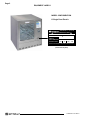
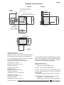
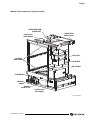
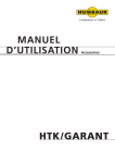
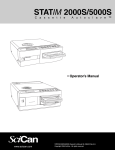
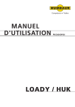
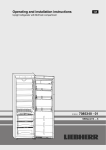
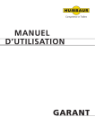
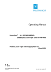
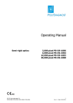
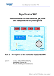
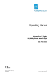
INSTALLATION INSTRUCTIONS
SKYTRON I3 Washer-Disinfector
TEC-F-0001 REV 1
4/12
TABLE OF CONTENTS
Page 1
TITLEPAGE
EQUIPMENT LABELS............................................................................................................................. 2
DRAWINGS & SPECIFICATIONS........................................................................................................... 3
SECTION I TECHNICAL SPECIFICATIONS / CONNECTIONS............................................................. 4
1-1 General Specifications................................................................................................................. 4
1-2 Utility Connection Specifications.................................................................................................. 4
1-3 Water Supply Connection Specifications..................................................................................... 7
1-4 Electrical Connection Specifications............................................................................................ 7
SPECIAL USER ATTENTION................................................................................................................. 8
GENERAL SAFETY GUIDELINES......................................................................................................... 10
SECTION II PREPARATION.................................................................................................................. 11
2-1 Preparatory Work........................................................................................................................ 11
2-2 Receiving - Damaged Shipment Claim Procedure..................................................................... 11
2-3 Unpacking................................................................................................................................... 11
2-4 Transportation Route.................................................................................................................. 12
SECTION III INSTALLATION................................................................................................................. 13
3-1 Washer/Drain Assembly Installation........................................................................................... 13. 3-2 Water Supply Connections......................................................................................................... 13
3-3 Chemical Supply Connections.................................................................................................... 14
3-4 Electrical Supply Connections.................................................................................................... 14
SECTION IV TEST AND CALIBRATION................................................................................................ 15
4-1 Keypad Navigation...................................................................................................................... 15
a. Entering Numeric Values...................................................................................................... 15
b. Menu/keypad Navigation..................................................................................................... 15
4-2 Set Up......................................................................................................................................... 16
4-3 Special Service Level................................................................................................................. 16
4-4 Diagnose Level........................................................................................................................... 17
4-5 Chemical Pump Calibration........................................................................................................ 18
4-6 System Final Test....................................................................................................................... 21
INSTALLATION CHECK LIST................................................................................................................ 23
MENUS
........................................................................................................................................... 24
Although current at the time of publication, SKYTRON’S policy of continuous development makes this
manual subject to change without notice.
I3 INSTALL ● REV1
Page 2
EQUIPMENT LABELS
MODEL CONFIGURATION
I3 Single Door Electric
GRAND RAPIDS, MI · 1.616.656.2900
! REFER TO ACCOMPANYING DOCUMENTS !
ELECTRICAL RATING
I3
MODEL NO.
SERIAL NO.
DATE OF FABRICATION
ELECTRICAL RATING
208V
3Ph
60Hz
11KW
Manufactured for SKYTRON by BHT HYGIENETECHNIK, GERSTHOFEN, GERMANY
SERIAL NUMBER TAG
(reverse side of panel)
I3 INSTALL ● REV1
Page 3
Drawings & Specifications
Front View
Side View
building-side drain valves with 3/4”
hose connection. Accessible for
machine’s operators.
26.8” (680)
cover plate
EL
option: exhaust air condenser
FFB
34.6” (880)
with cover plate
FFB
310
AL
500
310
700
Printer
VE
34.6” (880)
with cover plate
HW CW DI D
33.5” (850)
under counter model
1200
Dis
pla
y
EL
26.8” (680)
machine
33.5” (850)
under counter model
Main switch
by customer
0
250
150
300
350
450
space for media
31.5” (800)
machine
31.7” (805)
required space
631.5
AL
680
INNOVA M3
680
cover plate
ventilation slots
Top View
Heat loss: 1707 BTU/hr
Operating Weight: 331 lbs. (150 Kg)
Dimensions: 31.5”W x 26.8”D x 34.6”H (800 x 680 x 880 mm)
All measurements refer to finished floor and finished wall.
It is recommended that shut-off valves and vacuum breakers
(by others) be installed on all service lines.
Flexible hoses provided for services connections.
It is required that a three phase, fused Main Disconnect Switch
(with lockout in OFF position; by others) be installed in electrical
supply lines immediately near the equipment. Electrical
connections must be installed according to NEC.
Cold Water (CW) - 3/4” NPT
Flow pressure:: 29-75 PSI (2-5 bar)
Capacity : 5 gallons/min
Electrical Connection (EL)
208VAC, 3Ph, Ll + L2 + L3 + G
Electric dryer and sump: 35AMP, 11kW
Hot Water (HW) - 3/4” NPT
Temperature: 160°F
Flow pressure: 29-75 PSI (2-5 bar)
Capacity: 5 gallons/min
Consumption per cycle: 14.8 gal. (5.6L)
Drain (D) - 3/4” NPT Machine Side Discharge.
DI Water (DI) - 3/4” NPT
Flow pressure: 29-75 PSI (2-5 bar)
Capacity: 5 gallons/min
Consumption per cycle: 3.7 gal. (14L)
I3 INSTALL ● REV1
Vent (VE) - Direct Connection not recommended (in-direct
vent hood utilizing seamless non-corrosive vent materials
recommended).
* Not applicable if I3-CON Exhaust Condenser is installed.
Unit to be used only in specified environmental conditions:
Temperature: 5°- 40°C (41°- 104°F)
Relative Humidity: 30% to 95% (non condensing moisture)
Page 4
SECTION I TECHNICAL SPECIFICATIONS / CONNECTIONS
1-2 Utility Connection Specifications
1-1. General Specifications
Weight: Dimensions:
*All dimensions refer
wall.
331 lbs. (150 Kg)
31.5”W x 26.8”D x 33.5”H (800x680x880)*
to finished floor and finished
It is recommended that water shut-off valves and
vacuum breakers (by others) be installed on all
service lines. Flexible hoses are provided for service
connections. Hoses extend approximately 5 feet
from the back of the machine.
- Packaged Unit Dimensions & Weight
- Waterline connection color code:
Size:
Weight:
40"W x 30"D x 40"H
460 lbs.
- Package Contents
• Unit
• Drain Plumbing package
• Header Rack
• I-Series Performance Kit
For the connection of the SKYTRON I3 WasherDisinfector to the facility water supply, all local/
national regulations must be followed.
Install all the electrical connections in accordance with
the NEC standards and local/national regulations.
Red: Blue: Yellow: HW (hot water)
CW (cold water)
DI (de-ionized water)
- Cold Water (CW)
• Connection: • Flow pressure: • Capacity: ¾” NPT
29-75 P.S.I. (2-5 bar)
5 gal./min.
- Hot Water (HW)
• Connector: • Flow pressure: • Capacity: ¾” NPT
29-75 P.S.I. (2-5 bar)
5 gal./min.
- De-Ionized Water (DI)
• Connector: • Flow pressure: • Capacity: ¾” NPT
29-75 P.S.I. (2-5 bar)
5 gal./min.
NOTE
SKYTRON also recommends Reverse
Osmosis (RO) water or water from a
filtered source.
- Drain Service
The SKYTRON I3 Washer-Disinfector is supplied
with a 3/4" diameter Drain Hose that extends six (6)
feet from the back of the Washer.
• Capacity: 5 gal./min.
- Electrical Connection (EL)
208VAC, 3Ph, L1+L2+L3+G
- Power consumption
Electric dryer and sump: 35 Amp., 11KW
I3 INSTALL ● REV1
Page 5
Washer Front Component / System Location
UPPER SPRAY ARM
WATER INLET
NON-RETURN
CHECK VALVE
DOOR LATCH
ELECTRONICS
AIR FILTER
ROTATING
SPRAY ARMS
AIR HEATER
AIR TURBINE
FLOW METERS
CHEMICAL
PUMPS
MANUAL
DOOR LATCH
CONTROLLER
ENCLOSURE
I3 FRONT COMPONENTS
I3 INSTALL ● REV1
Page 6
Washer Rear Component / System Location
HOT
(RED)
COLD
(BLUE)
D.I.
(YELLOW)
LOW VOLTAGE
DOOR LOCK
LEVEL SWITCH
CONDENSER
(OPTION)
DOUBLE WATER
VALVE
SINGLE WATER
VALVE
AIR EXHAUST
PORT
CHEMICAL INLET
PORT
WATER INLET
CHAMBER
ADJUSTABLE
FEET
CIRCULATION
PUMP OUTLET
CHANNEL
ELECTRICITY
POWER
CONNECTION
BOX
MOVING CASTERS
CIRCULATION
PUMP
CIRCULATION PUMP
CAPACITOR
I3 REAR COMPONENTS
I3 INSTALL ● REV1
Page 7
1-3 Water Supply Connection Specification
1-4 Electrical Connection Specifications
The SKYTRON I3 Washer-Disinfector provides
three (3) Reinforced Water Intake Lines (hot, cold,
& DI) that extend five (5) feet from the back of the
Washer.
SKYTRON stipulates that the customer provide
a 208VAC, three phase, fused, Main Disconnect
Switch (with the lockout in the OFF position) near
the SKYTRON I3 Washer-Disinfector. Electrical
connections must be installed according to NEC
standards, following local and state electrical codes.
CAUTION
This washer requires that electrical connections are
made by a licensed electrician in accordance with
state, local, and national electrical codes using UL
(Underwriters Laboratory) recognized materials.
Flush all in-house water supply pipes
for a prolonged period of time before
the unit is connected. This will protect
the Washer from foreign particles
penetrating into the unit. SKYTRON
declines any responsibility for such
damages to the Washer caused by
contamination from the piping.
I3 INSTALL ● REV1
Page 8
SPECIAL USER ATTENTION
The following precautions should be reviewed by
all personnel prior to operating the SKYTRON I3
Washer-Disinfector.
WARNING
Indicates a possibility of personal injury.
CAUTION
Should any damage to the SKYTRON
I3 Washer-Disinfector be noted while
unpacking, further unpacking should be
discontinued. The container, with all the
wrapping, shall be held for inspection.
The transportation company must be
notified immediately so an inspector can
be sent. Read the Damaged Shipment
Claim Procedure for further details.
CAUTION
Indicates a possibility of damage to
equipment.
NOTE
Indicates important facts or helpful hints.
WARNING
Personnel unpacking the SKYTRON I3
Washer-Disinfector must use extreme
caution when removing the machine
from the package to prevent damage
to the machine and injury to themselves
or others.
CAUTION
CAUTION
Flush all in-house water supply pipes
for a prolonged period of time before
the unit is connected. This will protect
the Washer from foreign particles
penetrating into the unit. SKYTRON
declines any responsibility for such
damages on the Washer caused by
contamination from the piping.
Transport the SKYTRON I3 WasherDisinfector using a forklift truck or pallet
jack with appropriate lifting power and
suitable forks.
WARNING
The negligence of the safety
instructions may cause improper
Washer performance or endanger
operating personnel. Not following
safety instruction may lead to the loss
of warranty claims.
NOTE
The installation technician may be
required to change the order of steps
or modify the specifications of this
installation procedure to meet the
specific site installation requirements.
I3 INSTALL ● REV1
Page 9
NOTE
NOTE
Depending on the drain utilities provided
at the installation location, the Drain
Plumbing package has been provided
to facilitate making the Washer drain
connection into an existing sink drain.
Follow the installation instructions on
the Drain Plumbing package.
Two additional Chemical Pumps may
be added for a maximum of four Pumps
per Washer.
NOTE
Do not open the in-house water shut-off
valves at this time.
WARNING
Be careful when working with cleaning
and disinfection chemicals. Eyes, hands,
and clothes must be protected. Wear
safety glasses and gloves. Avoid contact
of eyes and skin with chemicals!
CAUTION
Ensure only non-foaming detergents are
used with the SKYTRON I3 WasherDisinfector.
NOTE
The SKYTRON I3 Washer-Disinfector
is supplied with two Chemical Siphon/
Level Sensors, one for e ach of the
two Chemical Pumps and Flow Meters.
They are designed to exit through
a knock-out hole in the back panel
and connect to a Chemical Supply
or Container next to the Washer. If
alternative chemical connections are
required, it is recommended to use
SKYTRON Chemical Extension Hose
(P.N. F3-040-99).
I3 INSTALL ● REV1
NOTE
Follow procedures in the Section
4-5, Chemical Pump Calibration, to
calibrate t he Chemical Pump/Flow
Meters.
WARNING
The connections of the SKYTRON I3
Washer-Disinfector to the Power Supply
must be carried out only by skilled
personnel. The applicable connection
data must be considered.
WARNING
Connect the Washer according to the
wiring diagram and ground in accordance
with the local and state electrical code.
Appropriate fuses and main switch will
be installed by customer.
NOTE
Watch the pump shaft until it slows down
to determine the direction of it's rotation.
If it is not rotating in the correct direction,
instruct the installation electrician to
change the electrical connections to
correct the phase problem.
Page 10
NOTE
NOTE
The I-Series Performance Kit (Part
No.F3-050-00) shipped with the
SKYTRON I3 Washer-Disinfector
includes a five gallon container of
Multi-Purpose Lube-Zyme Concentrate
Solution. The manufacturer suggests a
dilution ratio ranging from 1/4 ounce to
1 ounce per gallon.
The cycle can be aborted by pressing
the STOP key. The Control Panel Display
will show:
WARNING
Calibration of the Chemical Pump/
Flow Meters shall only be carried out
by a trained SKYTRON technician.
Otherwise, the cleaning and disinfection is not ensured.
CAUTION
WARNING
Avoid contact or inhalation of steam
that escapes from the Wash Chamber.
Severe burns may occur.
GENERAL SAFETY GUIDELINES
Installation instructions must be absolutely obeyed
and implemented. The installation technician must
pay attention to the following:
1. The installer must understand the instructions
and be able to execute them.
Always refer to the dilution rate indicated
on the chemical label for correct
calibration.
2. The installer must follow the instructions strictly
and carefully.
NOTE
4. Consider all the safety guidelines and hazard
warnings of the machine!
The chemical pump hoses and associated
components are empty and must be
"primed" before the chemical pumps can
be calibrated. Place Chemical Pump 1's
Chemical Siphon/Level Sensor into a
container of chemical and press the P16
- Rinsing Chemical System to initiate a
10 second pump cycle. Repeat this step
by pressing the P16 two times until you
observe chemical entering the Wash
Chamber through the Water Input Port.
Press the START key. The Chemical
Pump 1 system is now primed.
3. If necessary, or if required by regulations, use
personal protection equipment.
5. Do not make any changes, alterations or
attachment on the machine, without the approval
of SKYTRON.
6. Only trained personnel from SKYTRON may
implement program parameter alterations.
I3 INSTALL ● REV1
Page 11
SECTION II PREPARATION
2-1 Preparatory Work
2-3 Unpacking
SKYTRON recommends a pre-installation strategy
be developed to ensure the installation of the
SKYTRON I3 Washer-Disinfector is as effortless
and convenient as possible. Determine the kind and
place of installation for the SKYTRON I3 WasherDisinfector in advance. Prepare the required water/
drain and electrical supplies in accordance with the
connection plan.
The SKYTRON I3 Washer-Disinfector is shipped
in a wood crate mounted on a lift-truck accessible pallet. The packaged machine on the shipping
pallet measures 40”W x 30”D x 40”H and weighs
approximately 460 pounds. SKYTRON recommends
that the machine is unpacked at the receiving dock. 2-2 Receiving
The SKYTRON I3 Washer-Disinfector is delivered
in a suitable package. Please check the packing
immediately after receiving for outwardly recognizable
damages.
CAUTION
Should any damage to the SKYTRON
I3 Washer-Disinfector be noted while
unpacking, further unpacking should be
discontinued. The container, with all the
wrapping, shall be held for inspection.
The transportation company must be
notified immediately so an inspector can
be sent. Read the Damaged Shipment
Claim Procedure for further details
WARNING
Personnel unpacking the SKYTRON I3
Washer-Disinfector must use caution
when removing the machine from the
crate to prevent damage to the machine
and injury to themselves or others.
I3 INSTALL ● REV1
Page 12
2-4 Transportation Route
Included in the SKYTRON I3 Washer-Disinfector
shipping crate is a package containing the Operation/
Installation Manual, I-Series Performance Kit (Part
No. F3-050-00) and the Drain Plumbing Adaptors. Step 1
Disassemble the wood crate and discard.
Step 2
Remove the bubble-wrap from the Washer and
discard.
Step 3
Position the pallet jack forks so they are close
to the side of the pallet.
Step 4
Adjust the height of the pallet jack so it is even
with the top of the pallet.
Step 5
Carefully slide the Washer off the pallet until
the Washer is centered on the pallet jack forks.
Step 6
Prepare to transport the Washer to the
installation location.
The SKYTRON I3 Washer-Disinfector measures
31.5”W x 26.8”D x 33.5”H and weighs 331 pounds.
SKYTRON recommends that a transportation route
from the receiving dock to the installation location
be considered for height, width, and service elevator
accessibility with the machine sitting on a pallet jack
for transportation. CAUTION
Transport the SKYTRON I3 WasherDisinfector using a forklift truck or pallet
jack with appropriate lifting power and
suitable forks.
WARNING
The negligence of the safety
instructions may cause improper
Washer performance or endanger
operating personnel. Not following
safety instruction may lead to the loss
of warranty claims.
I3 INSTALL ● REV1
Page 13
SECTION III INSTALLATION
3-1. Washer/Drain Assembly Installation
NOTE
The installation technician may be
required to change the order of steps
or modify the specifications of this
installation procedure to meet the
specific site installation requirements.
Step 1
Carefully remove the Washer from the pallet
jack and place partially into the installation
location.
Step 2
Cut the tie-wrap at the back of the Washer
securing the three water intake lines. Unwrap
the lines.
Step 3
Cut the tie-wrap securing the 3/4" drain line.
Step 4
Remove the Drain Plumbing package from the
Wash Chamber.
NOTE
Depending on the drain utilities provided
at the installation location, the Drain
Plumbing package has been provided
to facilitate making the Washer drain
connection into an existing sink drain.
Follow the installation instructions on
the Drain Plumbing package.
I3 INSTALL ● REV1
3-2. Water Supply Connections
Step 1
Remove the package containing (3) 3/4"
NPT Adaptors (F1-010-65-1) and (1) Rubber
Washer (F1-010-65-2) from the I-Series
Performance Kit (Part No. F3-050-00)
Step 2
Locate the Water Supply Hose with the
tie-wrap securing three Hose Fitting Washers.
Cut the tie-wrap and collect the Washers.
Step 3
Place one (1) Hose Fitting Washer into each
of the three Water Supply Hose Fittings.
Step 4
Secure one (1) ¾” NPT Connection Adaptor to
each of the Washers’ three (3) Water Supply
Hoses Fittings.
Step 5
Connect and firmly secure the three (3) Water
Supply Hose Fittings to the in-house system
observing the following color code:
Red: HW (hot water)
Blue: CW (cold water)
Yellow:
DI (de-ionized water)
NOTE
Do not open the in-house water shut-off
valves at this time.
Page 14
3-3. Chemical Supply Connections
3-4. Electrical Supply Connections
Connect the unit according to the technical data
(See SECTION I TECHNICAL SPECIFICATIONS
/ CONNECTIONS on page 4).
SKYTRON stipulates that the customer provide
a 208VAC, three phase, fused, Main Disconnect
Switch (with the lockout in the OFF position) near
the SKYTRON I3 Washer-Disinfector. Electrical
connections must be installed according to NEC
standards, following local and state electrical codes.
WARNING
Be careful when working with cleaning
and disinfection chemicals. Eyes, hands,
and clothes must be protected. Wear
safety glasses and gloves. Avoid contact
of eyes and skin with chemicals!
CAUTION
Ensure only non-foaming detergents are
used with the SKYTRON I3 WasherDisinfector.
NOTE
The SKYTRON I3 Washer-Disinfector
is supplied with two Chemical Siphon/
Level Sensors, one for e ach of the
two Chemical Pumps and Flow Meters.
They are designed to exit through
a knock-out hole in the back panel
and connect to a Chemical Supply
or Container next to the Washer. If
alternative chemical connections are
required, it is recommended to use
SKYTRON Chemical Extension Hose
(P.N. F3-040-99).
WARNING
The connections of the SKYTRON I3
Washer-Disinfector to the Power Supply
must be carried out only by a certified
electrician. The applicable connection
data must be considered.
WARNING
Connect the Washer according to the
wiring diagram and ground in accordance
with the local and state electrical code.
Appropriate fuses and main switch will
be installed by customer.
Wire connection into fused disconnect box following
local and state electrical code.
NOTE
Two additional Chemical Pumps may
be added for a maximum of four Pumps
per Washer.
NOTE
Follow procedures in the Section
5-4, Chemical Pump Calibration, to
calibrate t he Chemical Pump/Flow
Meters.
I3 INSTALL ● REV1
Page 15
SECTION IV Test and Calibration
4-1 Keypad Navigation
a. Entering Numeric Values
b. Menu/Keypad Navigation
The SKYTRON I3 Washer-Disinfector’s control
panel features a dual purpose keypad. Its normal
mode of operation is for entering program navigation
commands as indicated by the symbols on the
individual key pads. When the START key pad LED
is blinking, the keypad is in the Numeric Keypad
Mode. Numbers can now be entered following the
keypad diagram shown below. Pressing the C4
key backspaces over entry errors. Pressing the
ENTER key returns the keypad to its normal mode
of operation.
To aid the user in entering keypad navigation
commands, all the available key pad options are
illuminated by a LED. All other key pads will not
function.
Normal Keyboard Settings
Cycle 1
STOP
Stop
The UP ARROW and DOWN ARROW keys provide
vertical movement into and out of submenu levels
as shown below.
The RIGHT ARROW and LEFT ARROW keys
provide horizontal movement through the submenus
levels and each submenu’s options. The user can
verify the results of their keypad actions on the
control panels two-line, 16-digit LCD alphanumeric
display.
Start
Cycle 2
Navigator Keyboard Settings
Cycle 3
Cycle 4-16
&
Backspace
Enter
STOP
Numeric Keyboard Settings
Up Arrow
Down Arrow
Left Arrow
Right Arrow
Figure 4-2.
Figure 4-1.
I3 INSTALL ● REV1
Page 16
4-2 Set Up
4-3 Special Service Level
Step 1
Open the three (3) in-house water shut-off
valves. Check for leaks and take appropriate
action.
To gain access to the SPECIAL SERVICE LEVEL one must enter a numeric access code. The
procedure to obtain this code is specified in the I3
Service Manual. Follow the steps below to enter
the SPECIAL SERVICE LEVEL.
Step 2
Place the Electrical Main Disconnect Switch
into the ON position. The washer will initiate
a power up/self-diagnose routine and a
sequence of messages will appear on the
display window until it ends with the following
message:
Step 1
Press the DOWN ARROW key.
Step 2
Press the START key. The zero's will flash on
and off.
Step 3
Thoroughly inspect the Water Supply Line
connections and Chemical Hoses for leaks.
Step 4
Press the STOP key.
Step 5
Press the RIGHT ARROW key two times. The
following messages will be displayed.
Step 3
Type the Service Code at the keypad.
Press the ENTER key.
Step 4
Press the DOWN ARROW key.
Step 5
Press the DOWN ARROW key.
I3 INSTALL ● REV1
4-4 Diagnose Submenu
In this submenu the output signals from the
Programmable Logic Controller (PLC) can be
tested. Exercise caution in this submenu. There
are no limiters activated in this submenu. Improper
handling may cause damage to the Washer.
Step 1
Press the DOWN ARROW key.
Page 17
NOTE
Watch the pump shaft until it slows down
to determine the direction of it's rotation.
If it is not rotating in the correct direction,
instruct the installation electrician to
change the electrical connections to
correct the phase problem.
Step 6
Press the RIGHT ARROW key until the Drain
Pump menu is displayed.
Step 2
Press the RIGHT ARROW key.
Step 3
Press the DOWN ARROW key.
Step 7
Verify this pump operation by pressing the
START key quickly two times to turn the pump
ON and then OFF.
Step 8
Press the RIGHT ARROW key until the Dryer
Turbine 1 menu is displayed.
Step 4
Press the RIGHT ARROW key until the
Circulation Pump menu is displayed.
Step 9
Verify the operation of the Turbine Motor by
pressing the START key quickly two times to
turn the motor ON and then OFF.
Step 5
Press the START key quickly two times to turn
the pump ON and then OFF.
I3 INSTALL ● REV1
Step 10
Press the RIGHT ARROW key until the
Chemical Pump 1 menu is displayed.
Page 18
Step 11
Verify the operation of Chemical Pump 1 by
pressing the START key quickly two times to
turn the pump ON and then OFF.
Step 12
Press the RIGHT ARROW key until the
Chemical Pump 2 menu is displayed.
4-5 Chemical Pump Calibration
Chemical pump calibration is determined by the
chemical/water dilution criteria for the particular
chemical being used by the facility.
Since chemical/water dilution criteria varies among
chemical manufacturers. You will need to adjust
your calibration to meet the chemical criteria at
your facility.
NOTE
Step 13
Verify the operation of Chemical Pump 2 by
pressing the START key quickly two times to
turn the pump ON and then OFF.
Step 14
Press the UP ARROW key until the Diagnose
Level Submenu is displayed.
The I-Series Performance Kit (P.N.
F3-050-00) shipped with the SKYTRON
I3 Washer-Disinfector includes a five
gallon container of Multi-Purpose
Lube-Zyme Concentrate Solution. The
manufacturer suggests a dilution ratio
ranging from 1/4 ounce to 1 ounce per
gallon.
WARNING
Step 15
Press the RIGHT ARROW key until the Basic
Setting Submenu is displayed.
Calibration of the Chemical Pump/
Flow Meters shall only be carried out
by a trained SKYTRON technician.
Otherwise, the cleaning and disinfection
effect is not ensured.
CAUTION
Step 16
Press the DOWN ARROW key.
Always refer to the dilution rate indicated
on the chemical label for correct
calibration.
A graduated vessel large enough to insert the
Chemical Siphon/Level Sensor into is required.
The ounces of liquid pumped per test cycle must
be able to be measured accurately.
Step 17
Press the RIGHT ARROW key three times.
Step 1
Press the DOWN ARROW key.
I3 INSTALL ● REV1
Page 19
Step 2
Press the DOWN ARROW key.
Step 5
Press the START key.
This is the default PARAMETER SETTING for
chemical pump No. 1. Both TYPE (TYP) and
TEMPERATURE (TEMP) can be edited. Step 6
Press the UP ARROW key.
TYP (0 or 1) is the method how the chemical is
monitored as it is being dispensed.
Type 0 = Monitored per time
Type 1 = monitored by the flow meter
TEMP is the temperature that the water must be
when the chemical is dispensed. This information
is found on the chemical data sheet.
Step 7
Press the RIGHT ARROW key.
We want the accuracy of the flow meters so TYP
1 will not be edited. The TEMP will be changed to
70° F.
Step 3
Press the START ARROW key. The "60" will
blink ON and OFF.
Step 4
Enter the sequence of "0, 7, 0" on the
keypad.
Press the ENTER key. The "1" will blink ON
and OFF.
Step 8
Press the DOWN ARROW key.
This is the default CHEMICAL (DOSING) SETTING
for chemical pump No. 1. Both TIME (T) and FLUID
OUNCE (2.40fl oz.) can be edited. T (time) is the time in seconds the chemical pump
is on. The number shown between "time" and "fl oz" is
the total counts the Flow Meter's electro/mechanical
counter sends during the chemical pump's ON TIME.
fl 0.00oz is for reference only. It's value does not
effect calibration. It is only entered to record the
amount of chemical dispensed.
I3 INSTALL ● REV1
Page 20
NOTE
The chemical pump hoses and associated
components are empty and must be
"primed" before the chemical pumps
can be calibrated. Place Chemical Pump
1's Chemical Siphon/Level Sensor into
a container of chemical and press the
P16 - Rinsing Chemical System to initiate
a 10 second pump cycle. Repeat this
step by pressing the P16 two times until
you observe chemical entering the Wash
Chamber through the Water Input Port.
Press the START key. The Chemical
Pump 1 system is now primed.
Step 13
Remove the Chemical Siphon/Level Sensor
from the graduated vessel.
View where the chemical line is on the graduated
scale. Subtract this level from the original level.
This will be the amount of chemical pumped in 10
seconds.
EXAMPLE: If 1.2 ounces was pumped in 10 seconds
and the goal is 2.5 ounces, then one could calculate
(2.5 ÷ 1.2 = 2.08 ) that 2.08 more time (21 seconds
total) is required to pump 2.5 ounces (2.08 x 1.2
= 2.5).
Step 9
Fill the graduated vessel with enough
chemical to have a clear initial reading.
Step 14
Place enough chemical in the graduated
vessel to return to the original level. Place
the Chemical Siphon/Level Sensor into the
graduated vessel.
Step 10
Insert Chemical Pump 1's Chemical Siphon/
Level Sensor into the graduated vessel filled
with chemical.
Step 15
Press the START key two times.
Enter the number sequence "2, 1".
Press the ENTER key.
Step 11
Press the START key. The "10" will blink ON
and OFF.
The "2.40" will blink ON and OFF. The Time
will begin to count down from 21 and the
Counter will begin to count up from 0.
Wait for the 38 second pump cycle to end.
Step 12
Press the ENTER key. The "2.40" will blink
ON and OFF. The Time will begin to count
down from 10 and the Counter will begin to
count up from 0.
Step 16
Remove the Chemical Siphon/Level Sensor
from the graduated vessel.
View where the chemical line is on the graduated
scale. Subtract this level from the original level.
This will be the amount of chemical pumped in 38
seconds.
Wait for the 10 second pump cycle to end.
If further adjustments are needed, follow Step 14
and Step 15 until the required chemical quantity is
measured. I3 INSTALL ● REV1
Page 21
4-6 System Final Test
Step 17
Type the number sequence "2, 5, 0" at the
keypad.
Press the ENTER key.
Press the START key.
The Washer's components have been checked and
calibrated. Now the Washer will run programs to
test it's operation.
Step 1
Press the C4 key seven times to access Wash
Cycle 10 - Rinse Cycle.
Step 18
Press the STOP key.
Step 2
Place enough chemical in the graduated
vessel to return to the original level. Place
the Chemical Siphon/Level Sensor into the
graduated vessel.
Step 19
Press the LEFT ARROW key two times.
Step 3
Press the START key.
The Washer will now automatically proceed
through all the steps of the Rinse Cycle.
Observe the entire operation for any unusual
signs.
Step 20
Open the I3 Washer door. Visually inspect
the Wash Chamber for damage. Ensure that
all the Filters are in place and free of debris.
Verify that the two (2) Wash Spray Arms rotate
freely.
NOTE
The cycle can be aborted by pressing
the STOP key. The Control Panel Display
will show:
Step 21
Inspect the Header for damage and ensure
the Header Spray Arms rotate freely.
Step 4
When the cycle is finished, the Control Panel
Display will show:
I3 INSTALL ● REV1
Page 22
WARNING
Avoid contact or inhalation of steam
that escapes from the Wash Chamber.
Severe burns may occur.
Step 5
Remove the Chemical Siphon/Level Sensor
from the graduated vessel.
Step 11
Open the Washer door and observe the
results of the Washer Performance Test
Packet.
Step 12
Place the Electrical Main Disconnect Switch
into the OFF position.
View where the chemical line is on the graduated
scale. Subtract this level from the original level to
verify that 2.5 ounces of chemical was pumped by
Chemical Pump 1.
Step 6
Place the Chemical Siphon/Level Sensors 1
into the appropriate Chemical Tanks.
Step 7
Press the C1 key to access Wash Cycle 1 Instrument Cycle.
Step 8
Locate the Washer Performance Test
Packet (F2-010-67) included in the I-Series
Performance Kit. Remove its contents and
follow the water quality test procedures
provided.
Step 9
Press the START key and the cycle will begin.
Step 10
When the cycle is finished, the Control Panel
Display will show:
I3 INSTALL ● REV1
Page 23
Installation Check List
Items to be checked during installation:
Unit leveled at installation.
Check date and item on display. Correct if required.
Water hoses connected with strainers and hose
washers.
Drain hose connected to the drain and drain
capped.
Electric service hard wired with breaker switch
close to unit.
Chemical bottles installed.
Chemical pumps primed.
Unused chemical siphon tubes have the floats
locked in the up position.
I3 INSTALL ● REV1
Chemical pumps calibrated.
Unit inspected for fluid leaks.
All protective film removed. Unit cleaned with
stainless steel cleaner.
P1 test cycles run and printout attached to this
installation sheet (optional).
Page 24
Skytron
I3
select
program
info level
submenu
I3
Vers. 76543210
date/time
15.02.2008/19:49
SERIAL NUMBER
01234567
ERROR/INFO
submenu
err 1 - data
err 2 - data
err 3 - data
err 4 - data
err 5 - data
err 6 - data
err 7 - data
err 8 - data
err 9 - data
err 10 - data
COUNTER
submenu
main counter
cycle counter start
cycle counter end
operation hours
1 – Instrument Cycle
2 – Short Instrument Cycle
3 – Basin & Bowl Cycle
4 – Mixed Load Cycle
5 – Heavy Inst. Cycle
6 – AN Equipment Cycle
7 – Glass Cycle
8 – Plastics Cycle
9 – Cannulated I Cycle
10 – Rinse Cycle
11 – User Defined
12 – User Defined
13 – User Defined
14 – User Defined
15 – Program 15
16 – Chemical Pump Rinse
I3 INSTALL ● REV1
Page 25
service level
submenu
service level
000000
special-service
submenu
diagnose - level
submenu
documentation
submenu
docu on/off
submenu
print program
submenu
printer
PC
print
program 01
I3 INSTALL ● REV1
technical-service
submenu
print error
submenu
print
error XXX
print parameter
submenu
analogvalues
submenu
basic parameter
dosing parameter
coding/releases
option
meter reading
TEMP TANK
TEMP DRYER
input-status
submenu
tank normal level
tank over level
door switch
reserve
reserve
reserve
reserve
reserve
reserve
reserve
reserve
reserve
reserve
coding 1
coding 2
coding 3
24V check
dos 1 empty
dos 2 empty
dos 3 empty
dos 4 empty
reserve
reserve
reserve
reserve
reserve
reserve
fail sterilfilt.
conduct.
PC-READY
reserve
reserve
output-status
submenu
CW valve
WW valve
DI valve
condenser
circ. pump
drain pump
Reserve
heating tank
turb. drying
turb. drying sof
heating dryer
dosing pump 1
dosing pump 2
dosing pump 3
dosing pump 4
Reserve
Reserve
Reserve
Reserve
Reserve
Reserve
Reserve
Reserve
reserve
PFC PRG_END
PFC PROG. ACTIV
PFC ERROR
PFC SPECIAL
Reserve
Reserve
door-magn.
reserve
Page 26
programming
submenu
release
submenu
programming
P (1-16)
glob param 1
Step 20 thru 2
rel. Option
submenu
glob param 2
Step 1
1 – Drain
2 – Drain V
3 – Drain/Regeneration
4 – PreWash
5 – PreWash V
6 – Wash
7 – Wash 104 F
8 – Wash 122 F
9 – Wash 140 F
10 – Neutralization
11 – Interm. rinse W
12 – Interm. rinse Di
13 – Final rinse DI
14 – Final rinse TH
15 – Chem. Disinf.
16 – Therm. Disinfection
17 – Special Step
18 – Condensate
19 – Drying
20 – Drying 140 F
21 – Drying 158 F
22 – Drying 176 F
23 – Drying 194 F
24 – Drying 212 F
25 – Drying 230 F
26 – Cooling
27 – Dosing rinse
28 – Preparation
29 – Program end
Step 2 thru 20
SCANNER
reserve
reserve
reserve
PROG.-SELECT
reserve
reserve
CONDENSER
prog-release
submenu
codes rack
submenu
prog 01 ACT/NONACT
prog 02 ACT/NONACT
prog 03 ACT/NONACT
prog 04 ACT/NONACT
prog 05 ACT/NONACT
prog 06 ACT/NONACT
prog 07 ACT/NONACT
prog 08 ACT/NONACT
prog 09 ACT/NONACT
prog 10 ACT/NONACT
prog 11 ACT/NONACT
prog 12 ACT/NONACT
prog 13 ACT/NONACT
prog 14 ACT/NONACT
prog 15 ACT/NONACT
prog 16 ACT/NONACT
code rack 01
code rack 02
code rack 03
code rack 04
code rack 05
code rack 06
code rack 07
I3 INSTALL ● REV1
Page 27
basic settings
submenu
date/time
15.02.2008/19:49
cycle oper.
NOT ACTIVE
SERIAL- NUMBER
01234567
country setting
submenu
language ENGLISH
date - format
SO/WI-Time
C°/F°
I3 INSTALL ● REV1
basic param
submenu
dosing
setting
main. Counter
BASIC_VOL_TANK
dryer heat-hyst
tank heat-hyst
DRY_Softrun
DRY_Draining
dosing-parameter
submenu
dos. calibr.
submenu
dosing 1
dosing 2
dosing 3
dosing 4
dosing 1
dosing 2
dosing 3
dosing 4
initialization
submenu
DISINFEC.PARAM.
submenu
mainten. counter
program-init.
basic parameter
TEMP-ADVANCE
DELAY-OVERTEMP
DELAY_UNDERTEMP
DEBOUNCE TIME
INADMIS.DEVIAT.
5085 Corporate Exchange Blvd. S.E.
Grand Rapids, MI 49512 • 1.616.656.2900 • FAX 1.616.656.2906