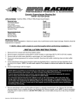
1
624H Repower Work Instructions
6068HF285-624H
Revision: C
27 July, 2010
Attention - Service Manager - Attention
Experience has shown that putting Tier 2 and Tier 3 power plants into engine compartments
designed for much older Tier 0 and Tier 1 models almost always involves trade-offs and
compromises. You need to be aware that the equipment options on your candidate machine may
differ from the options installed on the prototype unit used for kit development. Particular
examples might include cabs on bulldozers and the presence of air conditioning. In addition,
individual interpretations abound with respect to the “best way” to execute a repower. For these
reasons, Western Power Products will not be responsible for any additional cost an installing
dealer incurs to 1) adapt a kit to a machine configuration different from the machine used to
develop the kit or 2) to provide additional kit elements or alternate component mounts or
orientations employed to satisfy individual dealer preferences for their final repower product. So
before quoting, always start with a thorough review the installation instructions and engine codes
to identify potential areas you suspect might require additional material and labor. If you are
uncertain, talk to a Western Power Products’ engineer at 888-ENG-POWR or 661-397-9155.
They will help you develop a more complete picture of the scope of your repower project.
Table of Contents
624H Repower Work Instructions ................................................................................................................ 1
6068HF285-624H ......................................................................................................................................... 1
1 Parts....................................................................................................................................................... 4
2 Removing Old Engine........................................................................................................................... 5
3 Service Radiator .................................................................................................................................... 5
4 Installing New Engine........................................................................................................................... 5
5 Wiring and Wire Harness...................................................................................................................... 6
6 Modifying Controls ............................................................................................................................. 10
6.2
Key Switch .................................................................................................................................. 14
7 Hood Modifications ............................................................................................................................ 15
7.1
Air Cleaner Mounting ................................................................................................................. 16
7.2
Exhaust Mounting ....................................................................................................................... 17
Appendix A: 6068HF285 Engine Specification ......................................................................................... 21
Appendix B: Electronics ............................................................................................................................. 23
Figures and Tables
Figure 1: Radiator Removal .......................................................................................................................... 5
Figure 2: New Engine Installation ................................................................................................................ 5
Figure 3: CAC Tube Routing ........................................................................................................................ 6
Figure 4: Wiring Harness Routing ................................................................................................................ 6
Figure 5: Rear Left Wiring Harness Routing ................................................................................................ 7
Figure 6: Extension Harness to ECU ............................................................................................................ 7
Figure 7: ECU Mounting Location ............................................................................................................... 8
Figure 8: Pre-threaded Mounting Holes........................................................................................................ 8
Figure 9: Harness Routing Through ECU Compartment.............................................................................. 9
Figure 10: Underside of ECU Compartment ................................................................................................ 9
Figure 11: Modified Instrument Panel with PowerView ............................................................................ 10
Figure 12: RE534022B Instrument Panel Harness ..................................................................................... 11
Figure 13: Wiring Harness Routing Through Cab ...................................................................................... 11
Figure 14: AG-11 Analog Foot Throttle Wiring ......................................................................................... 12
Figure 15: Potentiometer Mounting On Accelerator Pedal......................................................................... 13
Figure 16: Underside of Accelerator with Potentiometer ........................................................................... 13
Figure 17: Key Switch ................................................................................................................................ 14
Figure 18: New Exhaust Stack and Air Cleaner Locations......................................................................... 15
Figure 19: Air Cleaner Mounting................................................................................................................ 16
Figure 20: Air Inlet Hose Routing .............................................................................................................. 16
Figure 21: Muffler Mounting Location ....................................................................................................... 17
Figure 22: Muffler Support Bracket............................................................................................................ 17
Figure 23: Mocked Up Muffler Support Bracket........................................................................................ 18
Figure 24: Muffler Support Bracket Base ................................................................................................... 19
Figure 25: CCV Tube Routing .................................................................................................................... 19
Figure 26: Muffler Support Bracket Modification for CCV ....................................................................... 20
Figure 27: Muffler Support ......................................................................................................................... 20
Figure 27: 21-pin Deutsch Instrument Panel Connector ............................................................................. 23
Figure 29: 21-pin Deutsch Instrument Panel and Controls ......................................................................... 23
Figure 30: Wiring Harness .......................................................................................................................... 24
1 Parts
Table 1: Parts List
CATEGORY
KIT
PART
QTY
DESCRIPTION
6068HF285-624H
CAC
50-250-300-110
51-250-300-300-110
WCT624A01
WCT624A02
AH170895
AT105289
2
2
1
1
6
2
2.5" COUPLER
2.5" TO 2" REDUCER
HOT CAC TUBE
COLD CAC TUBE
2.5" CLAMP
2" CLAMP
EXHAUST
M101171
9V15881
1
1
MUFFLER
EXHAUST CLAMP
RADIATOR
T181335
T181336
TY22472
1
1
4
RADIATOR HOSE
RADIATOR HOSE
RADIATOR HOSE CLAMP
ELECTRONICS
RE534022B
AT332120
AT332121
AT332122
1
1
1
1
INSTRUMENT PANEL
THROTTLE POTENTIOMETER
THROTTLE PEDAL HARNESS
THROTTLE PEDAL PLATE
AIR CLEANER
AT225535B
H88782
WRPAFT4ODA01
RE67747
28H1981
AT175358
AR64937
1675-202
135501-10825
1
2
1
4
4
1
2
1
1
AIR CLEANER KIT
AIR CLEANER ELBOW HOSE
4" OD X 16" AIR FLOW TUBE
HOSE CLAMP
SPACER
INTAKE RAINCAP
SUPPORT BAND
1/8" FITTING
FILTER
MISC
WRP624HA01
WRP624HA02
R522690
R120467
T178416
1
1
1
HOOD MODIFICATION TEMPLATE
ACCELERATOR PEDAL MOUNTING PLATE
AUX DRIVE GASKET
45 DEGREE CCV ELBOW FITTING
V-BELT
*Due to differences in configurations, you may need to supply miscellaneous mounting
hardware.
2 Removing Old Engine
•
•
Remove old engine according to the 624H Service Manual
Remove air cleaner mounting bracket from old engine – this will be used as the exhaust
mounting bracket on the new engine
3 Service Radiator
•
Check radiator and service if necessary
Figure 1: Radiator Removal
4 Installing New Engine
•
•
Install new engine per service repair manual
Reinstall hydraulic pump
Figure 2: New Engine Installation
Figure 3: CAC Tube Routing
•
•
5
•
•
•
•
Re-install radiator if it needed to be removed for service
Connect radiator hoses, new CAC pipes, fuel lines
Wiring and Wire Harness
Install wiring harness per service repair manual
Be sure to keep harness away from high temperature locations such as the exhaust
manifold
Connect sensors to engine
Secure harness to engine with zip ties
Figure 4: Wiring Harness Routing
Figure 5: Rear Left Wiring Harness Routing
•
Run excess wiring underneath the right side of the cab
Figure 6: Extension Harness to ECU
•
On the right side of the cab use a 13mm wrench and undo the 2 screws holding the access
panel closed.
Figure 7: ECU Mounting Location
Figure 8: Pre-threaded Mounting Holes
•
•
In the access panel, you will find 2 power control modules and wiring
Mount the engine control module to the pre-threaded holes on the wall that separates the
other power control module that it already installed; see Figure 8: Pre-threaded Mounting
Holes
Figure 9: Harness Routing Through ECU Compartment
Figure 10: Underside of ECU Compartment
•
With cutting torch, cut a hole below the ECU to route the wiring harness underneath the
cab to engine and connect to ECU
6 Modifying Controls
6.1.1 Power View Installation
Figure 11: Modified Instrument Panel with PowerView
•
•
•
•
•
•
•
•
•
•
Remove the harness, switches, key switch, and Power View from the instrument panel.
Figure 12: RE534022B Instrument Panel Harness
Using 1 ½ inch hole saw cut a hole next to the floorboard and the hydraulic control panel
Remove ashtray; PowerView will be installed in the old ash tray location
On the left hand side of the dash with 1 ½” hole saw cut a hole even with the ashtray
Route PowerView wiring connector to the hole on the left hand side of the dash
Connect the PowerView to CAN Bus and power
Install PowerView in ash tray location
Carefully route harness extension from the left side of the dash below and around the
right side of the cab. Ensure that the cable does not interfere or damage foot pedal
controls
Once past all foot pedals, lift up the floor mat and run harness around the contour of the
cab
Reinstall floor mat
Figure 12: RE534022B Instrument Panel Harness
Figure 13: Wiring Harness Routing Through Cab
•
Connect harness to the 21 pin connector through the 1 ½” hole previously drilled through
the cab and the hydraulic control box
6.1.2 Throttle Modification
The mechanical throttle linkage must be changed to accommodate the new electronic engine.
Replace the mechanical system with the throttle potentiometer.
•
•
•
•
Remove old pedal and cable
Install new pedal with provided WRP624HA02 bracket
Route throttle sensor wires through floor of cab and to 21 pin instrumentation and
controls connector on the wiring harness.
See AG11-P-11 for additional details on the foot throttle:
Figure 14: AG-11 Analog Foot Throttle Wiring
Figure 15: Potentiometer Mounting On Accelerator Pedal
Figure 16: Underside of Accelerator with Potentiometer
6.2 Key Switch
Figure 17: Key Switch
Key Switch
Install the wiring harness into the original key switch or transfer the key switch from the
RE534022B instrument panel.
7 Hood Modifications
The new engine configuration requires modifications to the hood to accept the new air cleaner
and exhaust. The Tier III 6068HF285 2 valve engine only comes in front exhaust configuration,
so the change from a rear exhaust engine to front exhaust necessitates the relocation of the air
cleaner.
See WRP624HA01 - HOOD MODIFICATION TEMPLATE for a 1:1 scale template of where to
cut the new holes for the exhaust stack. The old exhaust stack hole is used for the air cleaner.
The following figures point out the purpose of each modification to the hood:
• Mount Air Cleaner in old Exhaust Stack Location
• Mount the Exhaust Stack as shown in Figure 18: New Exhaust Stack and Air Cleaner
Locations
Figure 18: New Exhaust Stack and Air Cleaner Locations
•
Cut holes in hood according to WRP624HA01
o The drawing is a top view
o Align the drawing with the back edge of the hood and existing slot
o The portion to cut will create a second exhaust stack mount which looks like the
standard exhaust stack mount.
7.1 Air Cleaner Mounting
•
Install air cleaner in location of the previous muffler
Figure 19: Air Cleaner Mounting
•
Use washers to space the saddle brackets from the top of the hood
Figure 20: Air Inlet Hose Routing
•
Secure air inlet hose to turbo
7.2 Exhaust Mounting
Figure 21: Muffler Mounting Location
Figure 22: Muffler Support Bracket
•
The muffler support bracket will mount in the same location on the new engine
Figure 23: Mocked Up Muffler Support Bracket
•
•
•
•
Obtain a 22” X 3” piece of ¼” plate
Scribe a bend line 5” from one end, heat with a torch, and bend up 90 degrees
Filet weld the support to the muffler support bracket. You will need 2” gap from the
right side of the bracket. See Figure 23: Mocked Up Muffler Support Bracket for
completed bracket.
Using muffler mounting bracket from previous engine mock bracket to new engine and
with a pencil scribe the corner closest to the cab in a circular pattern to be ground
off/removed to clear valve cover oil cap.
Figure 24: Muffler Support Bracket Base
Figure 25: CCV Tube Routing
•
•
•
Remount bracket
With a pencil scribe the center of the bracket where the crank case ventilation hole and
valve cover come in contact
Install the R120467 – 45 DEGREE CCV ELBOW FITTING on the engine – the 90
degree fitting will not clear the exhaust support bracket.
Figure 26: Muffler Support Bracket Modification for CCV
•
•
•
•
Remove bracket and cut a circular hole in bracket as marked to obtain crank case
ventilation elbow
Remount bracket
Attach one AR64937 air cleaner saddle bracket to muffler. Mock up the vertical section
of plate to the saddle bracket and scribe mounting holes
Bolt air cleaner saddle bracket on the muffler to the exhaust support bracket.
Figure 27: Muffler Support
Appendix A: 6068HF285 Engine Specification
Table 2: Engine Option Codes
Product: PE 6068HF285 Diesel Engine (2684F) Specification Name: 6068HF285-624H
Final Specification Number: S022139
Create Date: 09Dec2009 Build Number: 2 Customer Name:
Code
Description
As Of
Date
09Dec2009
Base
PE 6068HF285 Diesel Engine (2684F)
1142
Rocker Arm Cover, Rear Fill, w/ John Deere Nameplate
1201
Oil Filler, RH, for use w/ Remote Mounted ECU
1324
Crankshaft Pulley, 168mm (6.6"), Standard Duty Damper, for Taper Nose Crank
1406
Flywheel Housing, SAE #3, LH, 3 Bolt Type 1 Starter Mount, Front Access for Torque Converter, Magnetic PU
1503
Flywheel for SAE #3, 11.5" OCC, 129 Tooth 8/10 Pitch Ring Gear
16A6
Fuel System, Denso HPCR w/ECU, 1000cc Flow Injector, Industrial - 116kW (155hp) thru149kW (200hp) and Gen-Set 147kW (197hp) & 177kW (237hp) at 1800RPM
1783
Air Intake, Vertical Intake
1909
Oil Pan, Aluminum, Deep Center Sump, 45° Int & 20° Cont. Off-Level, 19L
2156
Thermostat Cover, Vertical Outlet, Single Thermostat, Two Sensor Ports
2201
Thermostat, Single
2395
No Fan Housing, w/ Fan Mount Capability
2499
No Fan Belt
2699
No Engine Cylinder Block Heater
28AV
Exhaust Manifold, High Mount Turbocharger
2957
Vent System, 90° Elbow w/o Clamp, 1100mm (43") Vent Hose, Clamped to Right Side of Flywheel Housing
3041
24V Denso, 10 HP (7.5 kW), LH, 3-Bolt, Type 1 Mount, Gear Reduction
3142
24V, 45 Amp Bosch, w/ Wiring Harness
35ED
6.0", 2 Micron Final Fuel Filter, RH Side, Engine Mounted (contains port for optional low pressure fuel sensor)
3614
Front Plate, w/Aux-Drive, HPCR
3999
No Thermostat Housing (Cover Only)
4002
Dipstick, RH Side Service
4199
No Auxiliary Front Drive Pulley
4399
No Starting Aid
4434
Timing Gear Cover, Aux-Drive, w/ Fan Mount Support (High Mount Alternator)
5204
Base Engine Auxiliary Drive w/ Shipping Cover (less drive gear)
5399
No Fuel Heater
5569
Shipping Stand, Metal
5603
Industrial Yellow
5722
Water Pump Inlet, Downward Orientation w/ M18 Port
5902
Oil Cooler, 7 Plate
6099
No Auxiliary Fan Drive Pulley
6277
Alternator Mounting, High Position, Bosch 45-120 Amp, for Aux Drive
6387
Engine Mounted Primary Filter, High RH Rear Engine Mounted Final Filter - Air Compressor Compatible
6438
Exhaust Elbow
65RM
Turbocharger, High Mount, Industrial (High Power) & Gen-Set, RH Low Rear Oil Filter
6730
Base Engine Sensors
6901
Serial Number Plate
72MC
24V, 185HP, 138kW@2200, 4% PB, 31% TR
7499
No Air Conditioning Compressor Bracket
7899
No Air Compressor
8171
RH Side, Engine Mounted, High RH Side, 6.0", 30 Micron Primary Fuel Filter w/ Water Separator and W.I.F Sensor
83DR
ECU Software, John Deere Custom Performance - Industrial 138kW (185HP) thru 149kW (200HP) (500 Hour Oil Change
Interval)
8453
Remote Mounted ECU, 24V, w/wiring harness and hardware installed, ECU shipped loose, Distributor/OEM Installed, w/10
foot of harness, 402 mm fan height
8699
No Fan Pulley
8718
Belt Tensioner, Auto, High Mount & Low Mount Alternator, for use w/Aux-Drive
8843
Oil Filter, RH Low Rear
9109
Extension Harness - 21 Pin, Customer/Panel Interface Harness to Instrument Panel, 12 Foot (3.7M), Qty - 1 (packaged & shipped
w/engine)
9113
Customer/Panel Interface Harness, Remote Mounted ECU to Instrument Panel, packaged & shipped w/engine (contains the
21 & 23 pin connectors, 9 pin diagnostic connector, starter relay leads, power/ground leads, TVP, Aux Power, CAN
Terminator, Remote On
93GP
Emission Label, Tier 3 Industrial Applications (185hp / 138kW thru 200hp / 149kW)
9499
No Software Trim
Appendix B: Electronics
Figure 28: 21-pin Deutsch Instrument Panel Connector
Figure 29: 21-pin Deutsch Instrument Panel and Controls
Figure 30: Wiring Harness