1
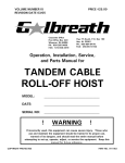
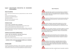
HT700 OWNERS MANUAL
Tag ##_____________________________________
Mileage In: _______________________
REMAN CENTER
Date Installed: __________________________
100% Associate Owned
WELLER REMAN
The Nation’s Complete Drivetrain Program!
Transmissions and Transfer Cases –
Quality Remanufactured by WELLER in
Grand Rapids, MI.
Light to Heavy Duty.
Borg Warner • Clark • Cotta • Fuller • FWD
• IHC • Isuzu • Mack/PAI • Meritor/Rockwell
• New Process GMC • New Venture • Noster
• Oshkosh • Spicer/TTC • ZF
A complete line of Auxiliaries and Transfer Cases.
Allison Transmissions –
Quality Remanufactured by WELLER in
Grand Rapids, MI.
Light to Heavy Duty.
An Authorized Allison Dealer in
Grand Rapids, MI, remanufacturing off-road
transmissions and components for Allison • Clark
• IHC • Dresser • Funk • Twin Disc • Borg Warner
Steering Gear Boxes and Pumps –
All units are tested on our state-of-the-art
XLT3 Road Simulator
TRW-Ross • Saginaw • Sheppard • Vickers Pumps
• ZF • Eaton • Luk
Differentials –
Complete Stock for quick exchange.
Clark • FWD • GMC • IHC • Industrial/Off Road
• Mack/PAI • Meritor/Rockwell • Spicer/Eaton
• Terex
THE WELLER REMAN NETWORK
2
PROGRAM
DESCRIPTION
Weller’s Unit Exchange program eliminates down time by getting you the parts you
need when you need them. With over 17,000 remanufactured transmissions and
differentials ready to ship, we can help you eliminate your or your customer’s downtime.
Consider becoming a key partner in the industry’s leading drivetrain program today. With
no commitments and no minimums, we are the industry partner for you!
Our aggressive reman program includes:
• All Makes Coverage – One Call
• Same Day Service
• Obsolete and Discontinued Specialists
• 17,000 Unit Stock – It’s Available
Today!
• Excellent Core Policy (call for
details)
• ASE-certified, manufacturer-trained
mechanics
• Technical Support on Questions
WELLER REMAN HAS THE ADVANTAGE!
THE WELLER REMAN NETWORK
3
ALLISON
TRANSMISSIONS
100% Genuine Allison
Outstanding Availability
Quality Remanufacturing
Every unit dyno tested
New Genuine Allison Torque
Converter on all AT Units
✔ Quality remanufactured
valve bodies matched to
original unit
✔ Priced for the best value
✔
✔
✔
✔
✔
Two year, unlimited mile warranty
on On-highway applications
Six month warranty on
Off-highway applications
Weller Reman Center,
Grand Rapids, MI is an
Authorized Allison Dealer
Popular Models
AT540 Series
1000/2000 Series
B400, B500
HD4560,HT740/750
MD3060, MT643…..
EVERYTHING!
Remanufactured by experts in Allison transmissions
THE WELLER REMAN NETWORK
4
DYNO TESTING
All transmissions are
dyno tested with a load
to simulate real truck
conditions.
Every transmission is
evaluated to ensure proper
torque,
accurate
shift points,
correct main
pressure, and
applied clutch
pressures. Gasket areas
are also
inspected for
leakage during
these tests.
THE WELLER REMAN NETWORK
5
INSTALLATION
GUIDE
VEHICLE MAKE AND MODEL ___________________________
MECHANIC’S NAME ___________________________________
TRANSMISSION ASSEMBLY NO. _______________________
VEHICLE ID NO. ________________________________________
I. PROPER TORQUE
• Flexplate bolts – ½ X 20: 96-115 ft lb (130-156 N-m), 3/8 X 24: 41-49 Ft lb .............................................
• Transmission housing to engine bell housing bolts (Tighten to vehicle manufacturers specifications) .........
• Transmission to frame or mounting bolts – 164-192 Ft lb (223-260 N-m) .................................................
• Output flange nut – 600-800 Ft lb (813-1085 N-m) ...................................................................................
• Companion flange or universal joint bolts (Tighten to manufacturer’s specifications)..................................
• Manual selector lever nut – 15-20 Ft lb (20-27 N-m). Thread on manual selector shaft changed to metric
effective MY 1978, S/N 20542. Nut torque remains unchanged ................................................................
• Modulator control retaining bolt, early models – 15-20 Ft lb (20-27 N-m); later models – 13-16 Ft lb
(18-22 N-m) ..............................................................................................................................................
• Oil filler tube nut – 90-100 Ft lb (122-136 N-m), 4.5" Pans 40-50 Ft lb, If Bolts 14-18 Ft lb......................
• Oil drain plug – 15-20 Ft lb (20-27 N-m) ...................................................................................................
• Speedometer driven gear assembly to rear cover – 45-50 Ft lb (61-68 N-m).............................................
• Neutral start switch to transmission housing – 50-60 Ft lb (68-81 N-m) ....................................................
• Reverse signal switch to transmission housing – 4-5 Ft lb (5-7 N-m) ........................................................
• Parking brake mounting bolts – 164-192 Ft lb (222-260 N-m) ..................................................................
• Oil lines to transmission – 50-60 Ft lb (61-68 N-m) ...................................................................................
• Bell cranks and cable support brackets to transmission – 54-65 Ft lb (73-88 N-m) ...................................
II. OIL COOLER, AIR AND VACUUM LINES
• Check for leaks .........................................................................................................................................
• Check for tightness of connections ............................................................................................................
• Check routing of lines................................................................................................................................
• Check for recommended line and fitting sizes (refer to AS45-035 or AS45-038) ........................................
¨
¨
¨
¨
¨
¨
¨
¨
¨
¨
¨
¨
¨
¨
¨
¨
¨
¨
¨
III. LINKAGE
Manual Selector
•
•
•
•
Check adjustment at all positions (refer to Service Manual, SA 1142, Section IV) .......................................
Check ease of movement ..........................................................................................................................
Check neutral safety switch (engine start in Neutral only) ..........................................................................
Check shift tower for correct detent and freedom of movement .................................................................
Mechanical Modulator Control
•
•
•
Check adjustment for proper shift points (full travel 1-3/16 to 1-9/16 in.; 30.16 to 39.69 mm) ..................
Check ease of movement ..........................................................................................................................
Check routing ............................................................................................................................................
Parking Brake
•
•
Adjust for proper clearance .......................................................................................................................
Adjust for full apply and release ................................................................................................................
THE WELLER REMAN NETWORK
6
¨
¨
¨
¨
¨
¨
¨
¨
¨
INSTALLATION
GUIDE
IV. DRIVELINE
• Check for proper indexing of slip and universal joints ................................................................................
• Determine if angles are within recommendations ......................................................................................
• Check for excessive backlash....................................................................................................................
• Lubricate universals and slip joints ............................................................................................................
¨
¨
¨
¨
V. FLUID SYSTEM
• TES 389-295 fluid being used ..................................................................................................................
• Oil level correct for operating conditions ....................................................................................................
• Dipstick properly marked (refer to Mechanic’s Tips, MT 1366 Section V) ....................................................
• Filler cap tight and vented .........................................................................................................................
• Filler tube tight at oil pan ...........................................................................................................................
• Breather clean and free of restriction.........................................................................................................
• Checked for oil leaks during operation.......................................................................................................
¨
¨
¨
¨
¨
¨
¨
VI. POWER TAKE OFF
• Backlash established.................................................................................................................................
• Controls connected and operative..............................................................................................................
• Properly coupled to driven equipment........................................................................................................
• Lube line from transmission properly routed and connected ......................................................................
¨
¨
¨
¨
VII. INSTRUMENTS, ELECTRICAL COMPONENTS
• Speedometer and odometer – operable .....................................................................................................
• Oil temperature and pressure gauges ........................................................................................................
• Wiring and electrical connections – functional ...........................................................................................
• Reverse signal circuit checked ..................................................................................................................
¨
¨
¨
¨
VIII. ROAD TEST VEHICLE
• Refer to Mechanic’s Tips, MT 1366, Section VI, for points to check
THE WELLER REMAN NETWORK
7
APPROVED
LUBRICANTS
TES-295
Approved Marketer
Product Brandname
AN-011001
Castrol Heavy Duty Lubricants
TranSynd
AN-031002
BP Lubricants
Autran Syn 295
AN-031003
Cognis Corporation
Emgard 2805
AN-031004
International Truck & Engine Company
Fleetrite Synthetic ATF
AN-051005
ExxonMobil Lubricants and Petroleum Specialties Company
Mobil Delvac Synthetic AFT
AN-071006
John Deere & Company
HD SynTran
AN-1010007
Volvo Trucks North America
Bulldog Synthetic ATF
AN-121009
Case New Holland
CNH HD Synthetic ATF
AN-121008
Shell International Petroleum Co. LTD.
Shell Spirax S6 ATF A295
Approval
Number
TES-389
Product Marketer
Product Brandname
NAmerica
CAmerica
Approval Number
BP Castrol
Castrol ATF Heavy Duty
Yes
Yes
AA-33182010
BP Castrol
Castrol ATF Heavy Duty
Yes
Yes
AA-33192010
BP Lubricants
Castrol Heavy Duty Multi-Purpose ATF
Yes
Yes
AA-32252007
BP Lubricants
Castrol Heavy Duty Multi-Purpose ATF
Yes
Yes
AA-32362007
Chevron Products Company
Chevron Automatic Transmission Fluid HD-389
Yes
Yes
AA-32012007
Chevron Products Company
Chevron Automatic Transmission Fluid HD-389
Yes
Yes
AA-32202007
Chevron Products Company
Chevron Automatic Transmission Fluid HD-389
Yes
Yes
AA-32242007
Chevron Products Company
Chevron Synthetic Automatic Transmission Fluid
Heavy Duty
Yes
Yes
AA-31992007
Chevron Products Company
Texaco Automatic Transmission Fluid HD-389
Yes
Yes
AA-32002007
ExxonMobil Lubricants &
Petroleum Specialties Co.
Mobile ATF D/M
Yes
Yes
AA-32792008
Fuchs Petrolub AG
Fuchs Titan ATF 4000
Yes
Yes
AA-32822010
Petro-Canada
Petro-Canada ATF D3M
Yes
Yes
AA-32082007
Ravensberger
Schmierstoffvertrieb GMBH
Ravenol ATF III H
Yes
Yes
AA-33072010
Shell International Petroleum
Co. LTD.
Spirax S2 ATF A389
Yes
Yes
AA-33242011
Shell Lubricants
Donax TA-389
Yes
Yes
AA-32212007
Shell Lubricants
Donax TX
Yes
Yes
AA-32332007
THE WELLER REMAN NETWORK
8
WHY SHIFT LINKAGE
IS IMPORTANT
The shift lever on a transmission moves inside the valve body, which distributes main pressure to the
various clutches in the transmission. If the valve is between two clutch ports, main pressure is restricted
to the clutches when the valve is operating. This can result in transmission failure.
Typical shift linkage adjustment complaints:
1.
2.
3.
4.
Shift lever (in cab) does not line up with the gear selected.
Slow engagement to forward or reverse.
Truck creeps forward or backward in neutral.
Reverse beeper operates intermittently in reverse or in neutral or not at all.
Correction:
One person is needed inside the cab and another person at the transmission shift lever. At the
transmission, remove the cotter key or retaining clip and remove the cable clevis pin from the
transmission shift lever. Have the person in the cab select each gear with the cable removed. Lock the
shifter in each gear while the person at the transmission moves the lever to its corresponding position
and reinserts the clevis pin in and out freely. This needs to be done in each gear. If the clevis pin fails to
line up with the lever after adjusting, some further diagnosis will be needed. Common issues for these
symptoms are a sticking cable, the lever or cable geometry is incorrect, or the lever id is too long or too
short. These are just some of the common causes to be checked if this problem would arise.
Why Modulator Adjustment Is Important:
The modulator is an external component attached to the transmission. They are typically mounted to
the rear half of the transmission directly behind the shift lever and neutral safety switch. Its function is
to vary the shift points depending on the throttle position. In other words, a part throttle condition (i.e.
city driving) will result in an “early” or lower up shift and a full throttle condition will result in a “later”
or higher up shift. What happens when the modulator is not working properly is an early or too soon
up shift at full throttle conditions. You may notice the engine RPM “flare” 200-300 RPM between shifts.
Driving a truck that shifts “too soon” will lug the engine and place undue stress on the transmission.
Imagine driving a manual transmission truck and you attempt a 3rd or 4th gear shift from a rolling stop.
The clutch will try to absorb this load from the output but the clutch will slip if it cannot. This same
theory applies with automatics.
There are Four Different Types of Modulators:
1. Cable Operated - One end will attach to the throttle linkage or directly to the accelerator
pedal. The transmission end uses a fulcrum to move the modulator pin. This cable will either
push or pull to full throttle depending on your vehicles set up.
2. Air - This modulator uses an air signal from the engine governor to move the modulator pin.
Williams Controls recommends changing the air modulator at each transmission service
(50,000 Miles).
3. Electric - Most commonly used with electronically governed engines where the governor has
no mechanical moving parts. Electric modulators are either on or off. They get their signal
from the engines ECU or data link translator to move the modulator pin.
(continued on page 10)
THE WELLER REMAN NETWORK
9
WHY SHIFT LINKAGE
IS IMPORTANT
(continued from page 9)
4. Vacuum- Only used on gas engines. Under full engine load, vacuum will drop off. This signal
is relayed to the modulator via a tube or hose, actuating a diaphragm inside the modulator
and releasing the plunger outward. Once there is no load, vacuum will return, pulling the
plunger back against spring pressure.
Typical Modulator Complaints:
Downshifts Hard
Cable Modulator - Cable at pedal or throttle linkage is not fully returning to its relaxed position.
You may need a return spring to help the cable back.
Vacuum Modulator - No vacuum signal or a torn diaphragm in modulator.
Air Modulator - Stuck plunger in modulator or full air pressure under all throttle positions.
Electric Modulator - Power to modulator, under all throttle positions.
Up shifts Hard (low RPM or too early)
Cable modulator - Cable not adjusted correctly or inoperable. To correctly adjust, push or pull the
throttle to full fuel. There should be no more than 1/8" slack left in the cable. Keep in mind there
are mechanical parts inside the box end of the cable that do wear.
Replacement of the cable may be necessary if adjustment won’t cure an early up shift.
Air modulator - Seals inside the modulator have worn allowing air pressure into the case. If there
is a lack of air pressure, or too low of pressure, the modulator may not function properly. If you
notice oil leaking out the breather, chances are the air modulator is leaking.
Electric Modulator - Modulator malfunction or no power to the modulator. This test will require
one person in the cab and one at the transmission. To check, loosen the retaining clip but do not
remove. With the ignition key on and the engine off, fully depress the throttle. This should push
the modulator away from the transmission if working properly. If there is no movement of the
modulator, further diagnosis will be required. Many times the problem is found with the relay or
in the vehicle wiring.
A harsh downshift may also be caused by higher than normal idle or slow to return throttle. It may
also be caused by a sticky transmission governor valve. An early up shift may be caused by using two
o-rings in the modulator valve. This happens quite often as most reman units are shipped with an o-ring
already installed in the case. BE SURE TO ONLY USE ONE “O” RING WHEN INSTALLING MODULATOR
OR MODULATOR PLUG!
THE WELLER REMAN NETWORK
10
ALLISON JOB AID
Allison Job Aid
SHIFT SELECTOR AND CABLE ADJUSTMENT PROCEDURE
For Allison Transmission Models:
1000 Product Family, 2000 Product Family, AT 500 Series, MT 600 Series,
HT / CLT 700 Series
The shift cable must be adjusted after the shift selector has been installed in its permanent mounting location, the
shift cable routing is finalized, and the cable has been secured.
NOTE: All changes to the shift cable routing,
including changes to the shift selector
location, will affect the adjustment of the
shift cable. Therefore, the shift cable must
be readjusted if its routing is modified by
a body builder or during transmission or
vehicle service.
“Gates” in
shift selector
permit transmission
detent to determine
actual selector
shaft orientation
When properly adjusted, the handle of a lever shifter
should be centered in each gate position when the
transmission selector shaft is held in place by the
internal transmission detent. See Figure C–2.
R
N
5
4
2
1
Figure C–2. Proper Shift Selector
Adjustment
Follow procedure below to attach and adjust the shift
selector cable at shift lever on the transmission.
SHIFT LEVER
HELD IN
NEUTRAL BY
TRANSMISSION
DETENT
1. With the engine off, set the park brake and block
the wheels to prevent vehicle movement.
CABLE
PIVOT
2. Place both the shift selector and the transmission
selector shaft in the Neutral position.
3. Attach the cable to the shift selector at the
operator’s station.
ñ
4. At the transmission end of the cable, push the
cable to move the shift handle against the end of
the shift selector Neutral gate. Note the position
of the pivot at the end of the cable with respect to
the hole in the shift lever. Refer to Figure C–3.
Push cable to move
selector handle against
end of NEUTRAL gate.
Figure C–3. Proper Shift Selector
Cable Adjustment
5. Pull the cable to move the shift handle against the opposite end of the shift selector Neutral gate. Note the
position of the pivot at the end of the cable with respect to the hole in the shift lever. Refer to Figure C–4.
6. Center the position of the cable at the midpoint of the travel determined by Steps 3 and 4. See Figure C–5.
JA3344EN (2008/01)
P.O. Box 894
Indianapolis, Indiana 46206-0894
(317) 242-5000
www.allisontransmission.com
THE WELLER REMAN NETWORK
11
ALLISON JOB AID
SHIFT LEVER
HELD IN
NEUTRAL BY
TRANSMISSION
DETENT
CABLE
SHIFT LEVER
HELD IN
NEUTRAL BY
TRANSMISSION
DETENT
PIVOT
CABLE
PIVOT
ñ
ñ
ñ
Center cable to midpoint of travel
(midway between “push” and “pull” positions).
Pull cable to move
selector handle against
opposote end of
NEUTRAL gate.
Figure C–5. Proper Shift Selector Cable
Adjustment
Figure C–4. Proper Shift Selector Cable
Adjustment
7. Holding the cable at the position determined in Step 5, rotate the pivot on the threaded section of the
cable end until it is aligned with the hole in the shift lever. See Figure C–6.
8. Verify that the attachment pin of the pivot does not bind in the shift lever hole and that the detent in the
transmission is positively engaged. This condition is sometimes called “free-pin-fit,” referring to lack of
friction at the cable / shift lever interface once
the transmission detent is engaged. Repeat
SHIFT LEVER
CABLE
Steps 4 through 6 as necessary to create this
HELD IN
NEUTRAL BY
condition.
TRANSMISSION
DETENT
PIVOT
ñ
9. Attach the pivot to the shift lever and secure with
the lock pin. If a jam nut is provided with the
cable hardware, torque the jam nut to lock the
pivot to the cable end as noted in Figure C–6. If
the cable manufacturer does not provide a jam
nut with the cable assembly, do not add one
during the installation process.
ññ
Rotate pivot on threaded end of cable
until it is aligned with hole in shift lever.
Verify “free pin fit” between pivot and
shift lever. Install lock pin and torque
jam nut (if present) to 8.5N-m (75 in-lb).
CAUTION: Once the jam nut is tightened,
the pivot pin should slide freely into the hole
in the lever. Do not twist the cable to insert it
into the lever. Loosen the jam nut, reorient
the pivot to insert freely into the lever, then
tighten the jam nut again.
Figure C–6. Proper Shift Selector Cable
Adjustment
10. Once this attachment is made, move the selector through all the range positions at the operator’s
station. Verify that free-pin-fit exists in each range position, and that the position of the shift lever is
determined by the internal transmission detent — not by tension or compression on the shift cable.
Special attention should be devoted to the free-pin-fit in the Neutral position, in the lowest forward
range (1), and, if available, in the Park or Park Brake position.
JA3344EN (2008/01)
www.allisontransmission.com
THE WELLER REMAN NETWORK
12
SERVICE TIPS
THE WELLER REMAN NETWORK
13
SERVICE TIPS
THE WELLER REMAN NETWORK
14
CORE RETURN
INSTRUCTIONS
The Weller Truck Parts core return program is designed to facilitate an efficient
and cost effective way of returning your cores. Following the instructions listed
below will insure your core is processed quickly and correctly.
1. Attach the Core Return Tag provided with the remanufactured unit
to core.
⦁ For warranty units, obtain a Warranty Repair Authorization (RA#) from your
Weller Truck Representative. If you are not sure who your representative is
call the Reman Center at 1-800-872-6697 or email [email protected].
2. Prepare the unit for shipping.
⦁ Drain oil from unit.
⦁ Band, wrap, or strap unit(s) to a pallet.
⦁ Attach a copy of the warranty invoice, core tag or RA# to the unit for
identification.
3. Notify Weller Shipping Department when unit is ready for pick up.
⦁ Email [email protected] or call 1-800-872-6697 Ext. 3794 or 3759
⦁ Provide the following:
◆ Core return tag # or Weller Truck Parts invoice # or the RA# if the unit is
a possible warranty
◆ Your contact information
◆ Hours of operation
⦁ Weller will prepare the bill of lading and schedule your unit to be picked up
by a Weller approved carrier.
Thank you for choosing Weller Truck Parts.
Failure to follow these procedures could result in core credit delays and freight charge backs.
www.wellertruck.com
THE WELLER REMAN NETWORK
15
WELLER WARRANTY
WARRANTY STATEMENT
Warranty Coverage
• Nationwide
Standard Warranty Coverage
Weller Reman Allison Transmissions for “on-highway” applications –
Two year, unlimited mileage – parts and labor. Weller Reman Allison
Transmissions for “off-highway” applications – Six months, unlimited
hours – parts and labor.
• Two Year
Coverage
Authorized Repair Points – Our Nationwide Warranty may be
administered only by an authorized warranty repair facility. Call
1-800-872-6697 for authorization.
• Unlimited
Mileage
• 800-872-6697
Tech Line
For
Troubleshooting
• Call For
Authorization
And
Assistance
• Metal tag must
not be removed
or warranty
will be void
Exclusions – Subject to the conditions stated herein, Weller warrants
to the original retail purchaser thereof that its Reman products
will, when used in a motor truck for on-highway or on/off-highway
applications in the United States and properly installed and
assembled on vehicles approved by the O.E.M. for such purpose, be
and remain under normal conditions of use and operation free from
failure due to defects in materials and workmanship from the date
of sale.
This warranty covers parts and labor to repair or replace, at Weller’s
option, the failed Weller component. Units installed as replacements
under this warranty are warranted only for the remainder of the
original warranty period.
This warranty shall not extend to failures or damage due to improper
lubrication or operation in excess of original design limitations,
failure to follow normal published preventive maintenance guidelines
of the O.E.M., abuse or damage by improper installation, casualty
or shipment.
This warranty shall not extend to repairs for noise (including idle
rattle), excessive operating temperature, transmission rear seal
leakage, nor does it cover failures caused by engine, clutch,
driveline; including transmission synchronizer pin breakage, or other
truck components or system.
This warranty does not cover failures caused by a worn, damaged
or defective part or component mounted to the unit by the dealer
or retail purchaser, including without limitation, the transmission
end yoke.
All warranty claims shall be made to Weller and shall be supported
by satisfactory evidence in respect of the conditions stated herein.
As a condition precedent to the allowance of such claims, the
component or assembly involved shall, if requested by Weller, be
returned prepaid to Weller for examination.
EXCEPT FOR THE EXPRESS WARRANTY STATED HEREIN,
WELLER DISCLAIMS ALL WARRANTIES, EXPRESS OR IMPLIED,
INCLUDING WITHOUT LIMITATION THE IMPLIED WARRANTIES
OF MERCHANTABILITY AND FITNESS FOR A PARTICULAR
PURPOSE. THE FOREGOING IS THE LIMIT OF THE LIABILITY OF
WELLER, AND IS THE EXCLUSIVE AND SOLE REMEDY OF THE
PARTY TO WHOM THIS WARRANTY IS MADE. LIABILITY ON THE
PART OF WELLER FOR DAMAGES, EXPRESSLY INCLUDING
CONSEQUENTIAL DAMAGES IS DISCLAIMED.
This warranty may not be changed or modified in any way except in
writing by Weller.
THE WELLER REMAN NETWORK
16
WELLER WARRANTY
CALL WELLER FIRST!
•
•
•
•
Possible Warranty
Have the Weller Tag or Invoice Number ready when calling.
Provide the Make/Model and vocation of the truck.
Provide a detailed description of the problem
Weller will issue a Repair Authorization #
Customer Repair
(In Place Fix)
Customer to determine failure/repair
cost and get Weller approval before
work is started.
Weller Repair
(R&R)
Weller to determine failure/repair cost
and get customer approval before
work is started.
(Exchange)
Weller ships replacement unit
Replacement unit is installed
Truck is up and running
Invoice your customer until
warranty process is complete
Non-Warranty
Warranty
• Complete the work
• Send the invoice to Weller.
The Repair Authorization # will
become the purchase order #.
• Weller will pay agreed amount
Unit Replaced
•
•
•
•
• If non-warrantable failure,
repair and dealers invoice your
customer.
• Weller will invoice for unit
repaired by Weller.
Customer returns possible warranty
unit to Weller for failure analysis
Weller performs failure analysis and
determines failure responsibility
Failure Analysis Not Complete
Failure Analysis Complete
Warranty
Dealers
Invoice your Customer
• Complete the work
• Send the invoice to Weller.
The Repair Authorization # will
become the purchase order #.
• Weller will pay agreed amount
Non-Warranty
• If non-warrantable failure,
repair and dealers invoice
your customer.
• Weller will invoice for unit
repaired by Weller.
THE WELLER REMAN NETWORK
17
WARRANTY CLAIM FORM
TAG #: ____________________
Date: _____________________
Claim Contact Information:
Vehicle Owner Information:
Name, Company, and Address:
Name, Company, and Address:
___________________________________
____________________________________
___________________________________
____________________________________
___________________________________
____________________________________
Phone: ___________________________
Phone: ____________________________
Fax: ______________________________
Fax: _______________________________
E-Mail: ___________________________
E-Mail: ____________________________
1500 Gezon Parkway SW
Grand Rapids, MI 49509
616-724-2000
800-872-6697
Fax 616-365-5679
Truck Information:
Make:
Model:
Mileage:
Vocation:
Engine:
VIN:
COMPLAINT
Description of the Problem:
Fluid Leak:
❏ Yes
❏ No
Shifting:
❏ Yes
❏ No
_______________________________________________________________________
Noise:
❏ Yes
❏ No
_______________________________________________________________________
Vibration:
❏ Yes
❏ No
_______________________________________________________________________
Hard Steering:
❏ Yes
❏ No
_______________________________________________________________________
Contamination:
❏ Yes
❏ No
_______________________________________________________________________
Other:
❏ Yes
❏ No
_______________________________________________________________________
_______________________________________________________________________
_______________________________________________________________________
ADDITIONAL INFO
Change with Speed?
❏ Yes ❏ No
Suspension Modified Recently?
❏ Yes ❏ No
Change with RPM?
❏ Yes
❏ No
Driveline in Phase?
❏ Yes ❏ No
During Acceleration?
❏ Yes
❏ No
Engine Mounts Checked?
❏ Yes ❏ No
During Deceleration?
❏ Yes
❏ No
King Pin Checked?
❏ Yes ❏ No
When Stationary?
❏ Yes
❏ No
Hydraulic Brakes?
❏ Yes ❏ No
Fluid at Proper Level?
❏ Yes
❏ No
System Flushed & Filter Replaced?
❏ Yes ❏ No
Fluid Clean?
❏ Yes
❏ No
Is the Unit Getting Hot?
❏ Yes
❏ No
Vehicle Towed?
❏ Yes
❏ No
Running PTO?
❏ Yes
❏ No
EMAIL TO: [email protected]
FAX TO: 616-365-5679, WELLER TRUCK PARTS WARRANTY
18
WELLER WARRANTY
Warranty
The following table shows warranty flat rates for
Allison transmissions:
It is essential that Weller is contacted
before the unit is removed from the vehicle
for warranty. Weller’s technician will assist
in troubleshooting the problem. If the unit
failed, the unit will be filmed, documented,
and warranty determined.
Allison Model
The following are the maximum flat rates for
failures due to defective products or
workmanship:
• Units do not have to be installed at a
Dealer to receive flat rate warranty
• Flat Rate Warranty is available on over
the counter sales
Flat Rate Credit
1000 SERIES GM APPL
$500
1000 SERIES STD APPL
$500
2000 SERIES
$500
2400 SERIES
$500
AT540, 542, 542N, 545
$500
AT545N, 545R
$500
B400R
$800
B500
$800
B500R
$800
HD4060, HD4060P, HD4560
$800
HT70, HT740, HT740RS
$800
HT750, HT750CRD, HT750DRD
$800
HT754, HT754CR, HT754CRD
$800
MD3060, MD3060P, MD3066P
$700
MD3560, MD3560P
$700
MT640, MT643
$600
MT650, MT653
$600
MT654
$600
Authorized Weller Dealers call for warranty labor hours guidelines.
THE WELLER REMAN NETWORK
19
THE WELLER REMAN NETWORK
20
16
10
5
15
6
18
23
1
9
21
7
3
24
19
13
14
17
2
4
8
12
11
22
1
Reman Center
1500 Gezon Pkwy S.W.
Grand Rapids, MI 49509
616-724-2000
800-872-6697
9
Detroit, MI
17
Nashville, TN
29826 W. Eight Mile Road
Farmington Hills, MI 48336
248-473-1900
800-473-1905
230 Molly Walton Drive
Hendersonville, TN 37075
615-264-2750
866-426-2750
2
Atlanta, GA
10
Gaylord, MI
18
Omaha, NE
3
Baltimore, MD
11
Houston, TX
19
St. Louis, MO
Birmingham, AL
12
Jacksonville, FL
20
Seattle, WA
5
Boise, ID
13
Las Vegas, NV
21
South Bend, IN
6
Chicago, IL
14
Los Angeles, CA
22
Tampa, FL
7
Columbus, OH
15
Milwaukee, WI
23
Salt Lake City, UT
24
Denver, CO
4
8
5007 Clark Howell Highway,
Suite A
Atlanta, GA 30349
404-768-9577
877-768-9577
899 Airport Park Rd., Ste. N
Glen Burnie, MD 21061
410-553-0443
877-550-0443
116 Total Solutions Way
Alabaster, AL 35007
205-685-0777
866-535-0777
8484 W. Victory Road
Boise, ID 83709
208-331-1061
888-331-1061
11152 Southwest Highway
Palos Hills, IL 60465
708-974-9919
888-974-9319
2885 International St.
Columbus, OH 43228
614-771-9500
866-771-9501
Dallas, TX
3113 Skyway Circle N
Irving, TX 75038
972-258-0460
855-258-0460
16
353 Expressway Court
Gaylord, MI 49735
989-731-6700
888-731-6700
4549 Aldine Bender
Houston, TX 77032
281-442-8855
877-677-8855
10330 Chedoak Court
Suite 205
Jacksonville, FL 32218
904-757-0777
888-474-0777
2985 Coleman St., Suite 14
North Las Vegas, NV 89032
702-638-8222
866-764-8222
9355 Cherry Ave.
Fontana, CA 92335
909-356-8322
877-356-8322
8625 North 107th
Milwaukee, WI 53224
414-354-6400
877-354-6400
Minneapolis, MN
3201 85th Avenue North
Brooklyn Park, MN 55443
763-424-3800
877-424-3802
8623 S. 117th St.
LaVista, NE 68128
402-597-9000
855-597-9001
2388 Chaffee Drive
Maryland Heights, MO 63146
314-692-2227
877-992-2227
6408 South 196th Street
Kent, WA 98032
253-872-0321
877-572-0321
3303 William Richardson Ct.
Suite 200
South Bend, IN 46628
574-237-1000
800-968-8860
217 Hobbs Street
Suite 103
Tampa, FL 33619
813-685-6100
866-685-6109
3450 W. California Ave.
Suite 400
Salt Lake City, UT 84104
801-886-0100
855-847-0100
Drive Train Industries