1
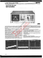
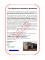
Test Equipment Solutions Datasheet
Test Equipment Solutions Ltd specialise in the second user sale, rental and distribution of
quality test & measurement (T&M) equipment. We stock all major equipment types such as
spectrum analyzers, signal generators, oscilloscopes, power meters, logic analysers etc from
all the major suppliers such as Agilent, Tektronix, Anritsu and Rohde & Schwarz.
We are focused at the professional end of the marketplace, primarily working with customers
for whom high performance, quality and service are key, whilst realising the cost savings that
second user equipment offers. As such, we fully test & refurbish equipment in our in-house,
traceable Lab. Items are supplied with manuals, accessories and typically a full no-quibble 2
year warranty. Our staff have extensive backgrounds in T&M, totalling over 150 years of
combined experience, which enables us to deliver industry-leading service and support. We
endeavour to be customer focused in every way right down to the detail, such as offering free
delivery on sales, covering the cost of warranty returns BOTH ways (plus supplying a loan
unit, if available) and supplying a free business tool with every order.
As well as the headline benefit of cost saving, second user offers shorter lead times, higher
reliability and multivendor solutions. Rental, of course, is ideal for shorter term needs and
offers fast delivery, flexibility, try-before-you-buy, zero capital expenditure, lower risk and off
balance sheet accounting. Both second user and rental improve the key business measure of
Return On Capital Employed.
We are based near Heathrow Airport in the UK from where we supply test equipment
worldwide. Our facility incorporates Sales, Support, Admin, Logistics and our own in-house
Lab.
All products supplied by Test Equipment Solutions include:
- No-quibble parts & labour warranty (we provide transport for UK mainland addresses).
- Free loan equipment during warranty repair, if available.
- Full electrical, mechanical and safety refurbishment in our in-house Lab.
- Certificate of Conformance (calibration available on request).
- Manuals and accessories required for normal operation.
- Free insured delivery to your UK mainland address (sales).
- Support from our team of seasoned Test & Measurement engineers.
- ISO9001 quality assurance.
Test equipment Solutions Ltd
Unit 8 Elder Way
Waterside Drive
Langley
Berkshire
SL3 6EP
T: +44 (0)1753 596000
F: +44 (0)1753 596001
Email: [email protected]
Web: www.TestEquipmentHQ.com
~
SPECTRUM ANAL VIER
MS71aC/D/EIF
10 kHz to 23 GHz (18 to 140 GHz)
GPIB
The MS710C/D/E/F has been designed as a high-performance microwave spectrum analyzer with wide user applications. The MS71OC/D/
E/F is easy-to-use and has a variety of functions suited to users' requirements.
Use of a simplified PLL synthesizer local oscillator gives a high accuracy of 30 kHz/6.5 GHz (MS710C/E) and a high resolution of 100
Hz/6 dB (=70 dB/3 dB).
Other features include wide dynamic range (second harmonics &-100
dB) and an optional, wide measurement frequency range of up to
140 GHz by using external mixers. This fundamental performance is
required by most users. In addition, a two-channel digital memory
enables simultaneous display of two measured data, display of subtraction results and processing functions such as MAX HOLD and
AVERAGING. By using these functions, the MS710C/D/E/F can provide many display/record-related functions such as signal search, and
marker point data readout for numeric display and direct plotting. A
new function which enables store/recall of up to 9 sets of measured
data and measurement conditions has also been added.
The MS710C/D/E/F has been designed for both easy manual operation
and completely automatic operation via GPIB. The design includes:
88
(1) a grouped key layout with different key sizes depending on their
functional importance, (2) an operation guide display for complicated
operations such as SHIFT and MARKER functions, and (3) a preset
memory which can memorize up to 10 sets of measurement conditions.
Main applications
. Spectrum analysis of microwave devices and components
. Spurious emission and spectral distribution measurements of analog
and digital communications transmitters
. Interference measurements for radio stations, satellite each stations, etc.
. Spectrum analysis in basic research such as nuclear physics and
radio-astronomy
. Spurious measurements
for home-use satellite broadcast receivers
and related equipment
Functions
. Wide variety of signal search functions
The special-purpose PEAK-CENTER SPAN UP/DOWN and HALF
SCREEN SHIFT keys enable rapid location of the desired signal.
/lnritsu
SPECTRUMANALYZERS
. Marker
Five marker functions (Normal, Delta, Peak, Marker -+ CF and Signal
Track) are provided. In Signal Track, during successive sweeps, the
marker continuously tracks the peak signal and at the start of each
sweep, the marker frequency is moved automatically to the center
frequency to hold the signal around the center of the screen. For the
convenience of users, Signal Track is automatically stopped when the
signal is lost. The photo shows the delta marker which enables reading of the frequency and level differences between two markers.
. List display based on operability
research
Five list displays enable effective use of the many functions. The displays are classified into two types: operation procedures and memory
contents. As an example of each type (1) the marker function list and
(2) measurement condition list are shown below.
Marker function list
Measurementcondition list
89
. SPECTRUMANALYZERS
---~
/lnritsu
Specifications
8100 kHz to 2 GHz and 1.7 to 23 GHz band
Model
MS710D/F
MS710C/E
--
100 Hz to 2 GHz, 1.7to 23 GHz
Measuring range
Setting range
Readout resolution
-, 0 MHzt02 GHz,1.71023GHz
100 kHz (0 MHz to 2 GHz)
1 MHz (1.7 to 23 GHz)
10 kHz (10 MHz 10 2 GHz)
10kHz (1.71023 GHz)
:t(the following accuracy +2% of frequency
Center frequency
Readout accuracy
Setting
span +10%
30 kHz (0 MHz 102 GHz, 1.7106.5 GHz)
60 kHz (6.510 12.5 GHz)
90 kHz (12.510 18.5 GHz)
120 kHz (18.510 23 GHz)
Number/unit
of resolution bandwidth)
1
2
3
4
MHz(OMHzt02GHz,1.7t06.5GHz)
MHz (6.5 to 12.5 GHz)
MHz (12.5 to 18.5 GHz)
MHz (18.5 to 23 GHz)
keys, data knob, peak center key, or half-screen
shift key
Setting range and resolution:
~
co
The following and 0 Hz (fixed tuning) in number/unit keys and in data knob
1 kHzldiv to 200 kHzldiv in 1 kHz increments
210 kHzldiv to 2 MHzldiv in 10 kHz increments
2.1 to 20 MHzldiv in 100 kHz increments
21 to 200 MHzldiv in 1 MHz increments
For span up/down keys: 1 kHzldiv to 200 MHzldiv in 1-2-5-10 sequence
Readout accuracy: :1:5% (6 kHzldiv to 200 MHzldiv), :1:10% (1 to 5 kHzldiv)
Setting: Number/unit keys, data knob, or span up/down keys
Frequencyspan
Q)
~
cr
~
u.
I In each band (span ~1 MHz)
Settingrange
In each band (span ~10 kHz)
Readout resolution
Min. 10 kHz (various with span settings)
(span = stop frequency - start frequency)
Start/stopfrequency
Readout accuracy
:f:(center frequency
Setting
Number/unit
accuracy)
+ 2.5%of
1 MHz (span ~200 MHz)
10 MHz (span ~210 MHz)
(span = stop frequency - start frequency)
span)
keys or data knob
Resolution
Resolution bandwidth (6 dB bandwidth)
Setting range: 100Hz to 3 MHz in 1-3-10 sequence
Setting: Selectable manually or automatically coupled to frequency span
Selectivity (60 dB/3 dB): ~10: 1 (resolution bandwidth ~1 kHz)
Stability
Residual FM: ~200 Hzp-p/0.1 s (center frequency; ~6.5 GHz, span; ~100 kHz/div)
Noise sidebands: ~-75 dB (1 kHz resolution bandwidth, 10 Hz video bandwidth, 30 kHz from signal, center
frequency ~6.5 GHz)
Measuring range
Graticule
LOG
Display
-
Reference
level
I Average noised level to +30 dBm
I Vertical 8 divisions. reference level is top line of graticule
10 dB/div: 0 to -70 dB from reference level
5 dB/div: 0 to -40 dB from reference level
2 dB/div: 0 to -16 dB from reference level
1 dB/div: 0 to -8 dB from reference level
UN
12.5%ldiv
Lineari~
:1:0.2 dB/1 dB, :1:1.5 dB/70 dB
Setting range: -109 to +30 dBm
Calibration output accuracy: -10 dBm :1:0.3 dB (100 MHz :1:10 kHz)
Reference level accuracy: :1:2.0 dB (reference level; -99 to -10 dBm, frequency; 100 MHz,
0 dB input attenuator, and after calibrated using CAL OUTPUT)
Input attenuator accuracy
Setting range: 0 to 70 dB, 10 dB steps, selected manually or automatically coupled to reference level
Error between steps: :1:1 dB (0 to 60 dB, 100 kHz to 2 GHz), :1:2 dB (0 to 40 dB, 100 kHz to 23 GHz)
Maximum accumulation error: :1:2.2 dB (0 to 60 dB, 100 kHz to 2 GHz), :1:3 dB (0 to 40 dB, 100kHz to 23 GHz)
Frequency response:
10 dB input attenuator after preselector peak adjustment to obtain maximum
:1:2.5 dB (100 kHz start frequency, 10 MHz stop frequency)
:I: 1.5 dB (10 MHz start frequency, 2 GHz stop frequency)
:1:2.5 dB (1.7 GHz start frequency, 5.48 GHz stop frequency)
:1:3 dB (5.48 GHz start frequency, 12.52 GHz stop frequency)
:1:4 dB (12.52 GHz start frequency, 23 GHz stop frequency)
response
Continued
90
on next page
Model
Dynamic range
Amplitude
MS71OC/E
MS710D/F
2nd harmonic distortion:
~-60 dB (input frequency 100 kHz to 10 MHz, value obtained by subtracting input attenuator value from input
level -40 dBm)
~ - 70 dB (input frequency 10 to 200 MHz, value obtained by subtracting input attenuator value from input level
-30 dBm)
~-80 dB (input frequency 200 to 850 MHz, value obtained by subtracting input attenuator value from input
level-30 dBm)
~ -1 00 dB * 1(input frequency 850 MHz to 11.5 GHz [1.7 to 23 GHz band], value obtained by subtracting input
attenuator value from input level-10 dBm)
Two signal 3rd intermodulation distortion:
~-80 dB (input frequency; 100 kHz to 2 GHz, frequency difference of two signal input; ~2.5 MHz, value
obtained by subtracting input attenuator value from input total level; -30 dBm)
~-100 dB*1 (input frequency; 1.7 to 12.5 GHz, frequency difference of two signal input; ~70 MHz, value
obtained by subtracting input attenuator value from input total level; -10 dBm)
~ -1 00 dB * 1(input frequency; 12.5 to 23 GHz, frequency difference of two signal input; ~ 100 MHz, value
obtained by subtracting input attenuator value from input total level; -10 dBm)
Residualresponse: ~-90 dBm (0 dB input attenuator,10 MHz to 6.5 GHz fundamentalmixing,and 50 Q termination)
Average noise level:
~-95 dBm (100 kHz to 1 MHz), ~-115 dBm (1 MHz to 2 GHz), ~-110 dBm (1.7 to 6.5 GHz),
~-100 dBm (6.5 to 12.5 GHz), ~-95 dBm (12.5 to 18.5 GHz), ~-88 dBm (18.5 to 23 GHz)
At 1 kHz resolution bandwidth, 0 dB input attenuator, and 3 Hz bandwidth
Video bandwidth:
1 Hz to 3 MHz, 1-3-10 sequence
Selected manually or automatically coupled to frequency span
Connector: N-lype (nominal 50 Q)
Maximum input level: +30 dBm, :to Vdc
! Frequency
and level at marker displayed
1/50 of span/div or 1 kHz whichever arealer
1/50 of span/div or 10 kHz whichever
areater
r 1/100 of span/div
Frequencyand level difference allwo markers displayed
1/50of span/div
Marker
Marker always tracks peak position and shows frequency
resolution)
Marker frequency
and level (readout resolution
.
same as Normal Marker
set to center frequency
CRT
Display area: 80 mm x 100 mm
Display item: Graticule, signal traces, function setting value, error message, title, frequency band list, shift function
list, and memory list
Signal traces
Memory capacity: Horizontal 501 points, vertical 801 points, A and B traces, backed-up by battery
Display: NORMAL, MAX HOLD, AVERAGE, A--B, A+-+B
CRT display
Function setting memory
Up to 10 sets of each function setting can be saved or recalled. The memory list can be displayed on the CRT,
backed-up
by battery.
Up to 9 sets of display (title, function settings, signal trace) can be saved or recalled.
Sweep time:
2 ms/div to 10 s/div. May be selected manually or automatically coupled to frequency span, resolution bandwidth,
and video bandwidth. For 0 Hz frequency span, 21Js/div to 10 s/div with manual setting. When (stop frequency
- start frequency) >2 GHz, the previous time is set and time cannot be set manually.
Sweep
Trigger: Signal, free run, line, video, and external trigger
Remote-control
-
GPIB (IEEE488, IEC625-1 , 24 pins), all front panel functions (expect power switch, CRT intensity, level calibration,
_and trigger level adjustment knob) can be remote-controlled.
CRT infom1ation can be plotted by the specified plotter or printer
--Power
Dimensions
AC 100 V :!:1g %,50/60 Hz, ~200 VA
and mass
* 1: Less than specified
177H X 426W X 451D mm, ~27
kg
level or average noise level
91
.
.10
i:;'
c:
Q)
OJ
c~
u.
kHz to 30 MHz band (MS710C)
-
1n kHzto 30 MHz
"
;
'C"?'C
Measuring frequency
Settingrange:0 kHzto 30 MHz
Center frequency
Readout resolution: 1 kHz
Readout accuracy: :t(3 kHz +2% of frequency
---
Frequencyspan setting range
and resolution
FreQuencv response
Q)
"C
.~
~
«
/lnritsu
SPECTRUMANALYZERS
Dynamic range
,
span +10% of resolution
bandwidth)
The following and 0 Hz (fixed tuning) in number/unit keys and in data knob
1 to 200 kHz/div in 1 kHz increments
210 kHz/div to 2 MHz/div in 10 kHz increments
2.1 to 3 MHz/div in 100 kHz increments
I=nr .ooan up/down key~ 1 kHz/div to 2 MHz/div in 1-2-5-10 seQuence and 3 MHz/div
+1fi
fiR (10 kHz start frequency,
30 MHz stop frequency,
10 dB input attenuator)
2nd harmonic distortion:
~-60
dB (input frequency 10 to 300 kHz, value obtained by subtracting input attenuator value from input level -40 dam)
~ -70 dB (input frequency 300 kHz to 15 MHz, value obtained by subtracting input attenuator value from input level -30 dam)
Two signal 3rd intermodulation distortion:
~-70
dB (input frequency 10 to 100 kHz, frequency difference of two signal input ~-2.5
MHz, value obtained by
subtracting input attenuator value from input total level -30 dam)
Residual response: ~-90 dam
Average noise level:
~-95 dam (100 kHz to 1 MHz), ~-115 dam (1 to 30 MHz)
1 kH7 r.."nl,lfinn hRnriwirith n fIR innllt attenuator,, and
-- 3
-- Hz video bandwidth
,
* : Other specifications are the same as the 100kHz to 2 GHz and 1.7 to 23 GHz band specifications,
Continued
92
on next page
/lnritsu
SPECTRUMANALYZERS
Ordering
information
Please specify model/order number, name and quantity when ordering.
I Model/OrderNo.
. Printer
Manufacture
EPSON
. Recommended external waveguide mixer
Tektronix: WM780 series (18 to 140 GHz, 2 port type)
Hewlett Packard: 11970 series (18 to 110 GHz, 3 port type)
Note: An additional amplifier (such as MP11975A) is required when
using the HP11970 series mixer for local signal amplification.
. Measuringcable
Recommended measuring cables are as follows: (product of
JUNKOSHA Co., Ltd.)
(1) JUNFLON microwave coaxial cable assembly
(2) DGM010-02000EE (general type, 2 m, N-P, 3.1 dB loss at 10 GHz)
(3) DGM024-02000EE (low loss type, 2 m, N-P, 2.5 dB loss at 10 GHz)
N"m"
MS710C
MS710D
MS710E
MS71 OF
Main frame
Spectrum Analyzer
Spectrum Analyzer
Spectrum Analyzer
Spectrum Analyzer
J0104A
JO017
FO013 (FO011)
F0010
FO011
F0012
WO087AE
WO087BE
Standard accessories
Coaxial cord, 1 m (BNC-P-RG-55/UoN-P):
Power cord, 1 m (plug type must be specified.):
Fuse, 5 A or 2 A:
Fuse,1.6A:
Fuse, 2 A:
Fuse, 3.15 A:
MS7010 operation manual:
MS7010 service manual:
MS7100-01
Option
Occupied frequency
Optional
MP614A
JOOl8
(10 kHz to 23 GHz/18 to 140 GHz)
(100 kHz to 23 GHz/18 to 140 GHz)
(100 kHz to 23 GHz)
(100 kHz to 23 GHz)
bandwidth
calculation
1 pc
1 pc
2 pcs
1pcs
1 pcs
1 pcs
1 copy
1 copy
function
accessories
50 Q +--+ 75 Q Impedance Transformer
20 dB high power attenuator
(N-type connector, 10 W, DC to 18 GHz)
JO064A
Coaxial to 7 GHz band waveguide adaptor
(5.8 to 8.6 GHz, BRJ-7oN-J)
JO064C
Coaxial to 10 GHz band waveguide adaptor
(8.2 to 12.4 GHz, BRJ-10-N-J)
MP59B
Coaxial Switch (DC to 3 GHz)
J0114A
Coaxial cord, 1 m (N-P-RG-9A/U-N-P,
general use)
DGMO1O-{J2(XXJEE
Coaxial cord, 2 m (N-type connector, general use)
DGMO24.O2<XXJEE Coaxial cord, 2 m (N-type connector, low-loss type)
J0309
Mixer cable, 1 m (HRM-202BoRG58A/UoHRM-202B)
JOO04
Coaxial adaptor (N-P'SMA-J)
JOOOl
GPIB cable, 1 m
JOO08
GPIB cable, 2 m
J0409
Centronics cable, 1 m (for printer)
J0410
Centronics cable, 2 m (for printer)
B0115C
CRT hood
B0063
Carrying case (for standard type)
BO020
FronVrear cover (4U)
BO029
Stacking foot
BO038
Front handle kit (4U)
80043
Rack mount kit (4U)
MH680A
MH648A
MB23A
MB24A
Application
equipment
Tracking Generator
Pre-amplifier
Portable Test Rack
Portable Test Rack
---
93