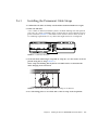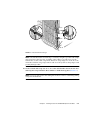
1
Sun Fire™ E25K/E20K Systems
Hardware Installation and Uninstallation Guide
Sun Microsystems, Inc.
www.sun.com
Part No. 817-4135-12
July 2005, Revision A
Submit comments about this document at: http://www.sun.com/hwdocs/feedback
Copyright 2005 Sun Microsystems, Inc., 4150 Network Circle, Santa Clara, California 95054, U.S.A. All rights reserved.
Sun Microsystems, Inc. has intellectual property rights relating to technology that is described in this document. In particular, and without
limitation, these intellectual property rights may include one or more of the U.S. patents listed at http://www.sun.com/patents and one or
more additional patents or pending patent applications in the U.S. and in other countries.
This document and the product to which it pertains are distributed under licenses restricting their use, copying, distribution, and
decompilation. No part of the product or of this document may be reproduced in any form by any means without prior written authorization of
Sun and its licensors, if any.
Third-party software, including font technology, is copyrighted and licensed from Sun suppliers.
Parts of the product may be derived from Berkeley BSD systems, licensed from the University of California. UNIX is a registered trademark in
the U.S. and in other countries, exclusively licensed through X/Open Company, Ltd.
Sun, Sun Microsystems, the Sun logo, AnswerBook2, docs.sun.com, Sun Fire, SunVTS, Sun Fireplane interconnect, Java, and Solaris are
trademarks or registered trademarks of Sun Microsystems, Inc. in the U.S. and in other countries.
All SPARC trademarks are used under license and are trademarks or registered trademarks of SPARC International, Inc. in the U.S. and in other
countries. Products bearing SPARC trademarks are based upon an architecture developed by Sun Microsystems, Inc.
The OPEN LOOK and Sun™ Graphical User Interface was developed by Sun Microsystems, Inc. for its users and licensees. Sun acknowledges
the pioneering efforts of Xerox in researching and developing the concept of visual or graphical user interfaces for the computer industry. Sun
holds a non-exclusive license from Xerox to the Xerox Graphical User Interface, which license also covers Sun’s licensees who implement OPEN
LOOK GUIs and otherwise comply with Sun’s written license agreements.
U.S. Government Rights—Commercial use. Government users are subject to the Sun Microsystems, Inc. standard license agreement and
applicable provisions of the FAR and its supplements.
DOCUMENTATION IS PROVIDED “AS IS” AND ALL EXPRESS OR IMPLIED CONDITIONS, REPRESENTATIONS AND WARRANTIES,
INCLUDING ANY IMPLIED WARRANTY OF MERCHANTABILITY, FITNESS FOR A PARTICULAR PURPOSE OR NON-INFRINGEMENT,
ARE DISCLAIMED, EXCEPT TO THE EXTENT THAT SUCH DISCLAIMERS ARE HELD TO BE LEGALLY INVALID.
Copyright 2005 Sun Microsystems, Inc., 4150 Network Circle, Santa Clara, Californie 95054, Etats-Unis. Tous droits réservés.
Sun Microsystems, Inc. a les droits de propriété intellectuels relatants à la technologie qui est décrit dans ce document. En particulier, et sans la
limitation, ces droits de propriété intellectuels peuvent inclure un ou plus des brevets américains énumérés à http://www.sun.com/patents et
un ou les brevets plus supplémentaires ou les applications de brevet en attente dans les Etats-Unis et dans les autres pays.
Ce produit ou document est protégé par un copyright et distribué avec des licences qui en restreignent l’utilisation, la copie, la distribution, et la
décompilation. Aucune partie de ce produit ou document ne peut être reproduite sous aucune forme, par quelque moyen que ce soit, sans
l’autorisation préalable et écrite de Sun et de ses bailleurs de licence, s’il y en a.
Le logiciel détenu par des tiers, et qui comprend la technologie relative aux polices de caractères, est protégé par un copyright et licencié par des
fournisseurs de Sun.
Des parties de ce produit pourront être dérivées des systèmes Berkeley BSD licenciés par l’Université de Californie. UNIX est une marque
déposée aux Etats-Unis et dans d’autres pays et licenciée exclusivement par X/Open Company, Ltd.
Sun, Sun Microsystems, le logo Sun, AnswerBook2, docs.sun.com, Sun Fire, SunVTS, Sun Fireplane interconnect, Java, et Solaris sont des
marques de fabrique ou des marques déposées de Sun Microsystems, Inc. aux Etats-Unis et dans d’autres pays.
Toutes les marques SPARC sont utilisées sous licence et sont des marques de fabrique ou des marques déposées de SPARC International, Inc.
aux Etats-Unis et dans d’autres pays. Les produits portant les marques SPARC sont basés sur une architecture développée par Sun
Microsystems, Inc.
L’interface d’utilisation graphique OPEN LOOK et Sun™ a été développée par Sun Microsystems, Inc. pour ses utilisateurs et licenciés. Sun
reconnaît les efforts de pionniers de Xerox pour la recherche et le développement du concept des interfaces d’utilisation visuelle ou graphique
pour l’industrie de l’informatique. Sun détient une license non exclusive de Xerox sur l’interface d’utilisation graphique Xerox, cette licence
couvrant également les licenciées de Sun qui mettent en place l’interface d’utilisation graphique OPEN LOOK et qui en outre se conforment aux
licences écrites de Sun.
LA DOCUMENTATION EST FOURNIE “EN L’ÉTAT” ET TOUTES AUTRES CONDITIONS, DECLARATIONS ET GARANTIES EXPRESSES
OU TACITES SONT FORMELLEMENT EXCLUES, DANS LA MESURE AUTORISEE PAR LA LOI APPLICABLE, Y COMPRIS NOTAMMENT
TOUTE GARANTIE IMPLICITE RELATIVE A LA QUALITE MARCHANDE, A L’APTITUDE A UNE UTILISATION PARTICULIERE OU A
L’ABSENCE DE CONTREFAÇON.
Contents
Regulatory Compliance Statements
ix
Safety Agency Compliance Statements
Preface
1.
2.
xxv
Preparing for Sun Fire E25K/E20K Systems Installation
1.1
Safety Precautions
1.2
Site Preparation
1–1
1–1
1–4
Installing the Sun Fire E25K/E20K Systems Hardware
2.1
Tools Required
2.2
Connecting Power Cables
2.3
Grounding the Cabinet
2.4
Connecting the System Controller
2.5
Connecting the Network Hardware
2.6
Managing I/O Cables
2.6.1
3.
xiii
2–1
2–1
2–2
2–4
2–7
2–7
2–8
Installing the Permanent Cable Straps
2.7
Completing the Installation
2.8
Powering On the System
2–9
2–12
2–13
Installing the Sun Fire E25K/E20K Systems Software
3–1
iii
4.
iv
3.1
Initial Domain Configuration
3–1
3.2
Running SunVTS on the Host
3–3
Uninstalling Sun Fire E25K/E20K Systems
4.1
Backing Up Your System
4.2
Deconfiguring the Domains
4.3
Preparing to Move the Cabinet
4.4
Preparing the Cabinet
4.5
Crating the Cabinet
4.6
Completing the Packaging
4–1
4–1
4–1
4–3
4–4
4–5
4–10
Sun Fire E25K/E20K Systems Hardware Installation and Uninstallation Guide • July 2005
Figures
FIGURE 2-1
AC Power Cord Installation
2–3
FIGURE 2-2
Sun Fire E25K/E20K Systems Grounding 2–4
FIGURE 2-3
System Board Power and ESD Connections 2–5
FIGURE 2-4
Ground Cable Attachment Point at System Cabinet 2–6
FIGURE 2-5
Cable Label Example
FIGURE 2-6
Black Cable Hanger Strap With Tie Wrap at Air Plenum
FIGURE 2-7
Black Permanent Straps
FIGURE 2-8
Green Cable Hanger Strap With Tie Wrap at Air Plenum 2–12
FIGURE 2-9
Circuit Breakers and Power Supplies
FIGURE 4-1
Retracted Leveling Feet 4–4
FIGURE 4-2
Cabinet Kick Plate Assembly Removal
FIGURE 4-3
Installed Ramps on Pallet Deck
FIGURE 4-4
Cabinet on Shipping Pallet Deck
FIGURE 4-5
Final Packaging and Outside Carton Packaging Assemblies 4–10
FIGURE 4-6
Cabinet Ready for Shipping 4–11
2–9
2–9
2–11
2–13
4–6
4–7
4–8
v
vi
Sun Fire E25K/E20K Systems Hardware Installation and Uninstallation Guide • July 2005
Tables
TABLE 1-1
Safety Precautions
1–2
TABLE 1-2
Symbols
TABLE 2-1
Cable Management Kit Contents
TABLE 4-1
Access Route Clearance
1–2
2–8
4–5
vii
viii Sun Fire E25K/E20K Systems Hardware Installation and Uninstallation Guide • July 2005
Regulatory Compliance Statements
Your Sun product is marked to indicate its compliance class:
•
•
•
•
Federal Communications Commission (FCC) — USA
Industry Canada Equipment Standard for Digital Equipment (ICES-003) — Canada
Voluntary Control Council for Interference (VCCI) — Japan
Bureau of Standards Metrology and Inspection (BSMI) — Taiwan
Please read the appropriate section that corresponds to the marking on your Sun product before attempting to install the
product.
FCC Class A Notice
This device complies with Part 15 of the FCC Rules. Operation is subject to the following two conditions:
1. This device may not cause harmful interference.
2. This device must accept any interference received, including interference that may cause undesired operation.
Note: This equipment has been tested and found to comply with the limits for a Class A digital device, pursuant to Part 15 of
the FCC Rules. These limits are designed to provide reasonable protection against harmful interference when the equipment
is operated in a commercial environment. This equipment generates, uses, and can radiate radio frequency energy, and if it is
not installed and used in accordance with the instruction manual, it may cause harmful interference to radio communications.
Operation of this equipment in a residential area is likely to cause harmful interference, in which case the user will be required
to correct the interference at his own expense.
Modifications: Any modifications made to this device that are not approved by Sun Microsystems, Inc. may void the authority
granted to the user by the FCC to operate this equipment.
FCC Class B Notice
This device complies with Part 15 of the FCC Rules. Operation is subject to the following two conditions:
1. This device may not cause harmful interference.
2. This device must accept any interference received, including interference that may cause undesired operation.
Note: This equipment has been tested and found to comply with the limits for a Class B digital device, pursuant to Part 15 of
the FCC Rules. These limits are designed to provide reasonable protection against harmful interference in a residential
installation. This equipment generates, uses and can radiate radio frequency energy and, if not installed and used in
accordance with the instructions, may cause harmful interference to radio communications. However, there is no guarantee
that interference will not occur in a particular installation. If this equipment does cause harmful interference to radio or
television reception, which can be determined by turning the equipment off and on, the user is encouraged to try to correct the
interference by one or more of the following measures:
•
•
•
•
Reorient or relocate the receiving antenna.
Increase the separation between the equipment and receiver.
Connect the equipment into an outlet on a circuit different from that to which the receiver is connected.
Consult the dealer or an experienced radio/television technician for help.
Modifications: Any modifications made to this device that are not approved by Sun Microsystems, Inc. may void the authority
granted to the user by the FCC to operate this equipment.
ix
ICES-003 Class A Notice - Avis NMB-003, Classe A
This Class A digital apparatus complies with Canadian ICES-003.
Cet appareil numérique de la classe A est conforme à la norme NMB-003 du Canada.
ICES-003 Class B Notice - Avis NMB-003, Classe B
This Class B digital apparatus complies with Canadian ICES-003.
Cet appareil numérique de la classe B est conforme à la norme NMB-003 du Canada.
x
Sun Fire E25K/E20K Systems Hardware Installation and Uninstallation Guide • July 2005
BSMI Class A Notice
The following statement is applicable to products shipped to Taiwan and marked as Class A on the product compliance
label.
T33012
GOST-R Certification Mark
xi
xii
Sun Fire E25K/E20K Systems Hardware Installation and Uninstallation Guide • July 2005
Safety Agency Compliance
Statements
Read this section before beginning any procedure. The
following text provides safety precautions to follow when
installing a Sun Microsystems product.
Depending on the type of power switch your device has,
one of the following symbols may be used:
On – Applies AC power to the system.
Off – Removes AC power from the system.
Safety Precautions
For your protection, observe the following safety
precautions when setting up your equipment:
■
■
■
Follow all cautions and instructions marked on the
equipment.
Ensure that the voltage and frequency of your power
source match the voltage and frequency inscribed on
the equipment’s electrical rating label.
Never push objects of any kind through openings in
the equipment. Dangerous voltages may be present.
Conductive foreign objects could produce a short
circuit that could cause fire, electric shock, or damage
to your equipment.
Symbols
The following symbols may appear in this book:
Caution – There is a risk of personal injury
and equipment damage. Follow the
instructions.
Standby – The On/Standby switch is in the
standby position.
Modifications to Equipment
Do not make mechanical or electrical modifications to the
equipment. Sun Microsystems is not responsible for
regulatory compliance of a modified Sun product.
Placement of a Sun Product
Caution – Do not block or cover the openings
of your Sun product. Never place a Sun
product near a radiator or heat register.
Failure to follow these guidelines can cause
overheating and affect the reliability of your
Sun product.
Noise Level
Caution – Hot surface. Avoid contact.
Surfaces are hot and may cause personal
injury if touched.
In compliance with the requirements defined in DIN 45635
Part 1000, the workplace-dependent noise level of this
product is less than 70 db(A).
Caution – Hazardous voltages are present. To
reduce the risk of electric shock and danger to
personal health, follow the instructions.
ix
SELV Compliance
Safety status of I/O connections comply to SELV
requirements.
Power Cord Connection
Caution – Sun products are designed to work
with power systems having a grounded
neutral (grounded return for DC-powered
products). To reduce the risk of electric shock,
do not plug Sun products into any other type
of power system. Contact your facilities
manager or a qualified electrician if you are
not sure what type of power is supplied to
your building.
Caution – Not all power cords have the same
current ratings. Do not use the power cord
provided with your equipment for any other
products or use. Household extension cords
do not have overload protection and are not
meant for use with computer systems. Do not
use household extension cords with your Sun
product.
The following caution applies only to devices with multiple
power cords:
Caution – For products with multiple power
cords, all power cords must be disconnected
to completely remove power from the system.
Battery Warning
Caution – There is danger of explosion if
batteries are mishandled or incorrectly
replaced. On systems with replaceable
batteries, replace only with the same
manufacturer and type or equivalent type
recommended by the manufacturer per the
instructions provided in the product service
manual. Do not disassemble batteries or
attempt to recharge them outside the system.
Do not dispose of batteries in fire. Dispose of
batteries properly in accordance with the
manufacturer’s instructions and local
regulations. Note that on Sun CPU boards,
there is a lithium battery molded into the realtime clock. These batteries are not customer
replaceable parts.
System Unit Cover
You must remove the cover of your Sun computer system
unit to add cards, memory, or internal storage devices. Be
sure to replace the cover before powering on your computer
system.
The following caution applies only to devices with a
Standby power switch:
Caution – Do not operate Sun products
without the cover in place. Failure to take this
precaution may result in personal injury and
system damage.
Caution – The power switch of this product
functions as a standby type device only. The
power cord serves as the primary disconnect
device for the system. Be sure to plug the
power cord into a grounded power outlet that
is nearby the system and is readily accessible.
Do not connect the power cord when the
power supply has been removed from the
system chassis.
x
Sun Fire E25K/E20K Systems Hardware Installation and Uninstallation Guide • July 2005
Rack System Warning
CD and DVD Devices
The following warnings apply to Racks and Rack Mounted
systems.
The following caution applies to CD, DVD, and other
optical devices.
Caution – For safety, equipment should
always be loaded from the bottom up. That is,
install the equipment that will be mounted in
the lowest part of the rack first, then the next
higher systems, etc.
Caution – To prevent the rack from tipping
during equipment installation, the anti-tilt bar
on the rack must be deployed.
Caution – To prevent extreme operating
temperature within the rack insure that the
maximum temperature does not exceed the
product’s ambient rated temperatures.
Caution – Use of controls, adjustments, or the
performance of procedures other than those
specified herein may result in hazardous
radiation exposure.
Conformité aux normes de sécurité
Veuillez lire attentivement cette section avant de
commencer. Ce texte traite des mesures de sécurité qu’il
convient de prendre pour l’installation d’un produit Sun
Microsystems.
Mesures de sécurité
Pour votre sécurité, nous vous recommandons de suivre
scrupuleusement les mesures de sécurité ci-dessous lorsque
vous installez votre matériel:
■
Caution – To prevent extreme operating
temperatures due to reduced airflow
consideration should be made to the amount
of air flow that is required for a safe operation
of the equipment.
■
■
Laser Compliance Notice
Sun products that use laser technology comply with Class 1
laser requirements.
Suivez tous les avertissements et toutes les
instructions inscrites sur le matériel.
Assurez-vous que la tension et la fréquence de votre
source d'alimentation correspondent à la tension et à
la fréquence indiquées sur l'étiquette de la tension
électrique nominale du matériel
N'introduisez jamais d'objets quels qu'ils soient dans
les ouvertures de l'équipement. Vous pourriez vous
trouver en présence de hautes tensions dangereuses.
Tout objet étranger conducteur risque de produire un
court-circuit pouvant présenter un risque d'incendie
ou de décharge électrique, ou susceptible
d'endommager le matériel.
Symboles
Class 1 Laser Product
Luokan 1 Laserlaite
Klasse 1 Laser Apparat
Laser Klasse 1
Vous trouverez ci-dessous la signification des différents
symboles utilisés:
Attention – Vous risquez d'endommager le
matériel ou de vous blesser. Veuillez suivre les
instructions.
Attention – Surfaces brûlantes. Evitez tout
contact. Les surfaces sont brûlantes. Vous
risquez de vous blesser si vous les touchez.
xi
Attention – Tensions dangereuses. Pour
réduire les risques de décharge électrique et
de danger physique, observez les consignes
indiquées.
Selon le type d'interrupteur marche/arrêt dont votre
appareil est équipé, l'un des symboles suivants sera utilisé:
Marche – Met le système sous tension
alternative.
Arret – Met le système hors tension
alternative.
Veilleuse – L'interrupteur Marche/Veille est
sur la position de veille.
Modification du matériel
N'apportez aucune modification mécanique ou électrique
au matériel. Sun Microsystems décline toute responsabilité
quant à la non-conformité éventuelle d'un produit Sun
modifié.
Positionnement d’un produit Sun
Attention – Evitez d'obstruer ou de recouvrir
les orifices de votre produit Sun. N'installez
jamais un produit Sun près d'un radiateur ou
d'une source de chaleur. Si vous ne respectez
pas ces consignes, votre produit Sun risque de
surchauffer et son fonctionnement en sera
altéré.
Niveau de pression acoustique
Le niveau de pression acoustique du lieu de travail définie
par la norme DIN 45 635 Part 1000 doit être au maximum de
70 db(A).
Conformité SELV
Connexion du cordon d’alimentation
Attention – Les produits Sun sont conçus
pour fonctionner avec des systèmes
d'alimentation équipés d'un conducteur
neutre relié à la terre (conducteur neutre pour
produits alimentés en CC). Pour réduire les
risques de décharge électrique, ne branchez
jamais les produits Sun sur une source
d'alimentation d'un autre type. Contactez le
gérant de votre bâtiment ou un électricien
agréé si vous avez le moindre doute quant au
type d'alimentation fourni dans votre
bâtiment.
Attention – Tous les cordons d'alimentation
ne présentent pas les mêmes caractéristiques
électriques. Les cordons d'alimentation à
usage domestique ne sont pas protégés contre
les surtensions et ne sont pas conçus pour être
utilisés avec des ordinateurs. N'utilisez jamais
de cordon d'alimentation à usage domestique
avec les produits Sun.
L'avertissement suivant s'applique uniquement aux
systèmes équipés d'un interrupteur Veille:
Attention – L'interrupteur d'alimentation de
ce produit fonctionne uniquement comme un
dispositif de mise en veille. Le cordon
d'alimentation constitue le moyen principal de
déconnexion de l'alimentation pour le
système. Assurez-vous de le brancher dans
une prise d'alimentation mise à la terre près
du système et facile d'accès. Ne le branchez
pas lorsque l'alimentation électrique ne se
trouve pas dans le châssis du système.
L'avertissement suivant s'applique uniquement aux
systèmes équipés de plusieurs cordons d'alimentation:
Attention – Pour mettre un système équipé de
plusieurs cordons d'alimentation hors tension,
il est nécessaire de débrancher tous les
cordons d'alimentation.
Le niveau de sécurité des connexions E/S est conforme aux
normes SELV.
xii
Sun Fire E25K/E20K Systems Hardware Installation and Uninstallation Guide • July 2005
Mise en garde relative aux batteries
Attention – Les batteries risquent d’exploser
en cas de manipulation maladroite ou de
remplacement incorrect. Pour les systèmes
dont les batteries sont remplaçables, effectuez
les remplacements uniquement selon le
modèle du fabricant ou un modèle équivalent
recommandé par le fabricant, conformément
aux instructions fournies dans le manuel de
service du système. N’essayez en aucun cas de
démonter les batteries, ni de les recharger hors
du système. Ne les jetez pas au feu. Mettez-les
au rebut selon les instructions du fabricant et
conformément à la législation locale en
vigueur. Notez que sur les cartes processeur
de Sun, une batterie au lithium a été moulée
dans l'horloge temps réel. Les batteries ne sont
pas des pièces remplaçables par le client.
Attention – Afin d'éviter que le rack ne
penche pendant l'installation du matériel, tirez
la barre anti-basculement du rack.
Attention – Pour éviter des températures de
fonctionnement extrêmes dans le rack,
assurez-vous que la température maximale ne
dépasse pas la fourchette de températures
ambiantes du produit déterminée par le
fabricant.
Attention – Afin d'empêcher des
températures de fonctionnement extrêmes
provoquées par une aération insuffisante,
assurez-vous de fournir une aération
appropriée pour un fonctionnement du
matériel en toute sécurité
Couvercle de l'unité
Pour ajouter des cartes, de la mémoire ou des périphériques
de stockage internes, vous devez retirer le couvercle de
votre système Sun. Remettez le couvercle supérieur en
place avant de mettre votre système sous tension.
Attention – Ne mettez jamais des produits
Sun sous tension si leur couvercle supérieur
n'est pas mis en place. Si vous ne prenez pas
ces précautions, vous risquez de vous blesser
ou d'endommager le système.
Avis de conformité des appareils laser
Les produits Sun qui font appel aux technologies lasers sont
conformes aux normes de la classe 1 en la matière.
Class 1 Laser Product
Luokan 1 Laserlaite
Klasse 1 Laser Apparat
Laser Klasse 1
Mise en garde relative au système en rack
La mise en garde suivante s'applique aux racks et aux
systèmes montés en rack.
Attention – Pour des raisons de sécurité, le
matériel doit toujours être chargé du bas vers
le haut. En d'autres termes, vous devez
installer, en premier, le matériel qui doit se
trouver dans la partie la plus inférieure du
rack, puis installer le matériel sur le niveau
suivant, etc.
Périphériques CD et DVD
L'avertissement suivant s'applique aux périphériques CD,
DVD et autres périphériques optiques:
Attention – L'utilisation de contrôles et de
réglages ou l'application de procédures autres
que ceux spécifiés dans le présent document
peuvent entraîner une exposition à des
radiations dangereuses.
xiii
Einhaltung sicherheitsbehördlicher
Vorschriften
Lesen Sie vor dem Ausführen von Arbeiten diesen
Abschnitt. Im folgenden Text werden Sicherheitsvorkehrungen beschrieben, die Sie bei der Installation eines
Sun Microsystems-Produkts beachten müssen.
Sicherheitsvorkehrungen
Treffen Sie zu Ihrem eigenen Schutz bei der Installation des
Geräts die folgenden Sicherheitsvorkehrungen:
■
■
■
Beachten Sie alle auf den Geräten angebrachten
Warnhinweise und Anweisungen.
Stellen Sie sicher, dass Spannung und Frequenz der
Stromversorgung den Nennleistungen auf dem am
Gerät angebrachten Etikett entsprechen.
Führen Sie niemals Fremdobjekte in die Öffnungen
am Gerät ein. Es können gefährliche Spannungen
anliegen. Leitfähige Fremdobjekte können einen
Kurzschluss verursachen, der einen Brand, Stromschlag oder Geräteschaden herbeiführen kann.
Symbole
Die Symbole in diesem Handbuch haben folgende
Bedeutung:
Achtung – Gefahr von Verletzung und
Geräteschaden. Befolgen Sie die Anweisungen.
Achtung – Heiße Oberfläche. Nicht berühren,
da Verletzungsgefahr durch heiße Oberfläche
besteht.
Achtung – Gefährliche Spannungen. Befolgen
Sie die Anweisungen, um Stromschläge und
Verletzungen zu vermeiden.
Je nach Netzschaltertyp an Ihrem Gerät kann eines der
folgenden Symbole verwendet werden:
Ein – Versorgt das System mit Wechselstrom.
Aus– Unterbricht die Wechselstromzufuhr
zum Gerät.
Wartezustand – Der Ein-/Standby-Netzschalter befindet sich in der Standby-Position.
Modifikationen des Geräts
Nehmen Sie keine elektrischen oder mechanischen
Gerätemodifikationen vor. Sun Microsystems ist für die
Einhaltung der Sicherheitsvorschriften von modifizierten
Sun-Produkten nicht haftbar.
Aufstellung von Sun-Geräten
Achtung – Geräteöffnungen Ihres SunProdukts dürfen nicht blockiert oder
abgedeckt werden. Sun-Geräte sollten niemals
in der Nähe von Heizkörpern oder Heißluftklappen aufgestellt werden. Die Nichtbeachtung dieser Richtlinien kann Überhitzung
verursachen und die Zuverlässigkeit Ihres
Sun-Geräts beeinträchtigen.
Lautstärke
Gemäß den in DIN 45 635 Teil 1000 definierten Vorschriften
beträgt die arbeitsplatzbedingte Lautstärke dieses Produkts
weniger als 70 dB(A).
SELV-Konformität
Der Sicherheitsstatus der E/A-Verbindungen entspricht
den SELV-Anforderungen.
xiv
Sun Fire E25K/E20K Systems Hardware Installation and Uninstallation Guide • July 2005
Anschluss des Netzkabels
Achtung – Sun-Geräte sind für
Stromversorgungssysteme mit einem
geerdeten neutralen Leiter (geerdeter
Rückleiter bei gleichstrombetriebenen
Geräten) ausgelegt. Um die Gefahr von
Stromschlägen zu vermeiden, schließen Sie
das Gerät niemals an andere Stromversorgungssysteme an. Wenden Sie sich an den
zuständigen Gebäudeverwalter oder an einen
qualifizierten Elektriker, wenn Sie nicht sicher
wissen, an welche Art von Stromversorgungssystem Ihr Gebäude angeschlossen ist.
Achtung – Nicht alle Netzkabel verfügen
über die gleichen Nennwerte. Herkömmliche,
im Haushalt verwendete Verlängerungskabel
besitzen keinen Überlastschutz und sind
daher für Computersysteme nicht geeignet.
Verwenden Sie bei Ihrem Sun-Produkt keine
Haushalts-Verlängerungskabel.
Warnung bezüglich Batterien
Achtung – Bei unsachgemäßer Handhabung
oder nicht fachgerechtem Austausch der
Batterien besteht Explosionsgefahr. Verwenden Sie bei Systemen mit austauschbaren
Batterien ausschließlich Ersatzbatterien
desselben Typs und Herstellers bzw. einen
entsprechenden, vom Hersteller gemäß den
Anweisungen im Service-Handbuch des
Produkts empfohlenen Batterietyp. Versuchen
Sie nicht, die Batterien auszubauen oder
außerhalb des Systems wiederaufzuladen.
Werfen Sie die Batterien nicht ins Feuer.
Entsorgen Sie die Batterien entsprechend den
Anweisungen des Herstellers und den vor Ort
geltenden Vorschriften. CPU-Karten von Sun
verfügen über eine Echtzeituhr mit integrierter Lithiumbatterie. Diese Batterie darf nur
von einem qualifizierten Servicetechniker ausgewechselt werden.
Gehäuseabdeckung
Die folgende Warnung gilt nur für Geräte mit StandbyNetzschalter:
Achtung – Beim Netzschalter dieses Geräts
handelt es sich nur um einen Ein/StandbySchalter. Zum völligen Abtrennen des Systems
von der Stromversorgung dient hauptsächlich
das Netzkabel. Stellen Sie sicher, dass das
Netzkabel an eine frei zugängliche geerdete
Steckdose in der Nähe des Systems angeschlossen ist. Schließen Sie das Stromkabel
nicht an, wenn die Stromversorgung vom
Systemchassis entfernt wurde.
Die folgende Warnung gilt nur für Geräte mit mehreren
Netzkabeln:
Achtung – Bei Produkten mit mehreren Netzkabeln müssen alle Netzkabel abgetrennt werden, um das System völlig von der Stromversorgung zu trennen.
Sie müssen die Abdeckung Ihres Sun-Computersystems
entfernen, um Karten, Speicher oder interne Speichergeräte
hinzuzufügen. Bringen Sie vor dem Einschalten des
Systems die Gehäuseabdeckung wieder an.
Achtung – Nehmen Sie Sun-Geräte nicht ohne
Abdeckung in Betrieb. Die Nichtbeachtung
dieses Warnhinweises kann Verletzungen oder
Geräteschaden zur Folge haben.
Warnungen bezüglich in Racks eingebauter
Systeme
Die folgenden Warnungen gelten für Racks und in Racks
eingebaute Systeme:
Achtung – Aus Sicherheitsgründen sollten
sämtliche Geräte von unten nach oben in
Racks eingebaut werden. Installieren Sie also
zuerst die Geräte, die an der untersten
Position im Rack eingebaut werden, gefolgt
von den Systemen, die an nächsthöherer Stelle
eingebaut werden, usw.
xv
Achtung – Verwenden Sie beim Einbau den
Kippschutz am Rack, um ein Umkippen zu
vermeiden.
Achtung – Um extreme Betriebstemperaturen
im Rack zu vermeiden, stellen Sie sicher, dass
die Maximaltemperatur die Nennleistung der
Umgebungstemperatur für das Produkt nicht
überschreitet
Normativas de seguridad
Lea esta sección antes de realizar cualquier operación. En
ella se explican las medidas de seguridad que debe tomar al
instalar un producto de Sun Microsystems.
Medidas de seguridad
Para su protección, tome las medidas de seguridad
siguientes durante la instalación del equipo:
■
■
Achtung – Um extreme Betriebstemperaturen
durch verringerte Luftzirkulation zu vermeiden, sollte die für den sicheren Betrieb des
Geräts erforderliche Luftzirkulation eingesetzt
werden.
Hinweis zur Laser-Konformität
Sun-Produkte, die die Laser-Technologie verwenden,
entsprechen den Laser-Anforderungen der Klasse 1.
Class 1 Laser Product
Luokan 1 Laserlaite
Klasse 1 Laser Apparat
Laser Klasse 1
CD- und DVD-Geräte
Die folgende Warnung gilt für CD-, DVD- und andere
optische Geräte:
■
Siga todos los avisos e instrucciones indicados en el
equipo.
Asegúrese de que el voltaje y frecuencia de la fuente
de alimentación coincidan con el voltaje y frecuencia
indicados en la etiqueta de clasificación eléctrica del
equipo.
No introduzca objetos de ningún tipo por las rejillas
del equipo, ya que puede quedar expuesto a voltajes
peligrosos. Los objetos conductores extraños pueden
producir cortocircuitos y, en consecuencia, incendios,
descargas eléctricas o daños en el equipo.
Símbolos
En este documento aparecen los siguientes símbolos:
Precaución – Existe el riesgo de que se
produzcan lesiones personales y daños en el
equipo. Siga las instrucciones.
Precaución – Superficie caliente. Evite todo
contacto. Las superficies están calientes y
pueden causar lesiones personales si se tocan.
Precaución – Voltaje peligroso. Para reducir
el riesgo de descargas eléctricas y lesiones
personales, siga las instrucciones.
Achtung – Die hier nicht aufgeführte
Verwendung von Steuerelementen,
Anpassungen oder Ausführung von
Vorgängen kann eine gefährliche
Strahlenbelastung verursachen.
xvi
Sun Fire E25K/E20K Systems Hardware Installation and Uninstallation Guide • July 2005
En función del tipo de interruptor de alimentación del que
disponga el dispositivo, se utilizará uno de los símbolos
siguientes:
Encendido – Suministra alimentación de CA
al sistema.
Apagado – Corta la alimentación de CA del
sistema.
Espera – El interruptor de encendido/espera
está en la posición de espera.
Modificaciones en el equipo
No realice modificaciones de tipo mecánico ni eléctrico en el
equipo. Sun Microsystems no se hace responsable del
cumplimiento de normativas en caso de que un producto
Sun se haya modificado.
Colocación de un producto Sun
Precaución – No obstruya ni tape las rejillas
del producto Sun. Nunca coloque un producto
Sun cerca de radiadores ni fuentes de calor. Si
no sigue estas indicaciones, el producto Sun
podría sobrecalentarse y la fiabilidad de su
funcionamiento se vería afectada.
Nivel de ruido
De conformidad con los requisitos establecidos en el
apartado 1000 de la norma DIN 45635, el nivel de ruido en
el lugar de trabajo producido por este producto es menor de
70 db(A).
Conexión del cable de alimentación
Precaución – Los productos Sun se han
diseñado para funcionar con sistemas de
alimentación que cuenten con un conductor
neutro a tierra (con conexión a tierra de
regreso para los productos con alimentación
de CC). Para reducir el riesgo de descargas
eléctricas, no conecte ningún producto Sun a
otro tipo de sistema de alimentación. Póngase
en contacto con el encargado de las
instalaciones de su empresa o con un
electricista cualificado en caso de que no esté
seguro del tipo de alimentación del que se
dispone en el edificio.
Precaución – No todos los cables de
alimentación tienen la misma clasificación
eléctrica. Los alargadores de uso doméstico no
cuentan con protección frente a sobrecargas y
no están diseñados para su utilización con
sistemas informáticos. No utilice alargadores
de uso doméstico con el producto Sun.
La siguiente medida solamente se aplica a aquellos
dispositivos que dispongan de un interruptor de
alimentación de espera:
Precaución – El interruptor de alimentación
de este producto funciona solamente como un
dispositivo de espera. El cable de alimentación
hace las veces de dispositivo de desconexión
principal del sistema. Asegúrese de que
conecta el cable de alimentación a una toma
de tierra situada cerca del sistema y de fácil
acceso. No conecte el cable de alimentación si
la unidad de alimentación no se encuentra en
el bastidor del sistema.
Cumplimiento de la normativa para
instalaciones SELV
Las condiciones de seguridad de las conexiones de entrada
y salida cumplen los requisitos para instalaciones SELV (del
inglés Safe Extra Low Voltage, voltaje bajo y seguro).
xvii
La siguiente medida solamente se aplica a aquellos
dispositivos que dispongan de varios cables de
alimentación:
Precaución – En los productos que cuentan
con varios cables de alimentación, debe
desconectar todos los cables de alimentación
para cortar por completo la alimentación
eléctrica del sistema.
Advertencia sobre las baterías
Precaución – Si las baterías no se manipulan
o reemplazan correctamente, se corre el riesgo
de que estallen. En los sistemas que cuentan
con baterías reemplazables, reemplácelas sólo
con baterías del mismo fabricante y el mismo
tipo, o un tipo equivalente recomendado por
el fabricante, de acuerdo con las instrucciones
descritas en el manual de servicio del
producto. No desmonte las baterías ni intente
recargarlas fuera del sistema. No intente
deshacerse de las baterías echándolas al fuego.
Deshágase de las baterías correctamente de
acuerdo con las instrucciones del fabricante y
las normas locales. Tenga en cuenta que en las
placas CPU de Sun, hay una batería de litio
incorporada en el reloj en tiempo real. Los
usuarios no deben reemplazar este tipo de
baterías.
Cubierta de la unidad del sistema
Debe extraer la cubierta de la unidad del sistema
informático Sun para instalar tarjetas, memoria o
dispositivos de almacenamiento internos. Vuelva a colocar
la cubierta antes de encender el sistema informático.
Precaución – No ponga en funcionamiento
los productos Sun que no tengan colocada la
cubierta. De lo contrario, puede sufrir lesiones
personales y ocasionar daños en el sistema.
xviii
Advertencia sobre el sistema en bastidor
Las advertencias siguientes se aplican a los sistemas
montados en bastidor y a los propios bastidores.
Precaución – Por seguridad, siempre deben
montarse los equipos de abajo arriba. A saber,
primero debe instalarse el equipo que se
situará en el bastidor inferior; a continuación,
el que se situará en el siguiente nivel, etc.
Precaución – Para evitar que el bastidor se
vuelque durante la instalación del equipo,
debe extenderse la barra antivolcado del
bastidor.
Precaución – Para evitar que se alcance una
temperatura de funcionamiento extrema en el
bastidor, asegúrese de que la temperatura
máxima no sea superior a la temperatura
ambiente establecida como adecuada para el
producto.
Precaución – Para evitar que se alcance una
temperatura de funcionamiento extrema
debido a una circulación de aire reducida,
debe considerarse la magnitud de la
circulación de aire requerida para que el
equipo funcione de forma segura.
Aviso de cumplimiento de la normativa para
la utilización de láser
Los productos Sun que utilizan tecnología láser cumplen los
requisitos establecidos para los productos láser de clase 1.
Class 1 Laser Product
Luokan 1 Laserlaite
Klasse 1 Laser Apparat
Laser Klasse 1
Sun Fire E25K/E20K Systems Hardware Installation and Uninstallation Guide • July 2005
Dispositivos de CD y DVD
La siguiente medida se aplica a los dispositivos de CD y
DVD, así como a otros dispositivos ópticos:
Precaución – La utilización de controles,
ajustes o procedimientos distintos a los aquí
especificados puede dar lugar a niveles de
radiación peligrosos.
Nordic Lithium Battery Cautions
Norge
Advarsel – Litiumbatteri — Eksplosjonsfare.
Ved utskifting benyttes kun batteri som
anbefalt av apparatfabrikanten. Brukt batteri
returneres apparatleverandøren.
Sverige
Varning – Explosionsfara vid felaktigt
batteribyte. Använd samma batterityp eller en
ekvivalent typ som rekommenderas av
apparattillverkaren. Kassera använt batteri
enligt fabrikantens instruktion.
Danmark
Advarsel! – Litiumbatteri — Eksplosionsfare
ved fejlagtig håndtering. Udskiftning må kun
ske med batteri af samme fabrikat og type.
Levér det brugte batteri tilbage til
leverandøren.
Suomi
Varoitus – Paristo voi räjähtää, jos se on
virheellisesti asennettu. Vaihda paristo
ainoastaan laitevalmistajan suosittelemaan
tyyppiin. Hävitä käytetty paristo valmistajan
ohjeiden mukaisesti.
xix
xx
Sun Fire E25K/E20K Systems Hardware Installation and Uninstallation Guide • July 2005
Preface
The Sun Fire E25K/E20K Systems Hardware Installation and Uninstallation Guide
provides procedures for installing and configuring the host hardware and software.
This document is for service personnel and customer data center staff who are
involved in the site preparation for and installation of the Sun Fire™ E25K/E20K
systems.
How This Book Is Organized
Chapter 1 details safety information and site preparation.
Chapter 2 describes the steps required for system hardware installation and testing.
Chapter 3 shows the steps required for software installation.
Chapter 4 defines the proper procedures for system shutdown and packaging prior
to relocating.
Using UNIX Commands
This document might not contain information on basic UNIX® commands and
procedures such as shutting down the system, booting the system, and configuring
devices. Refer to the following for this information:
■
Software documentation that you received with your system
■
Solaris™ Operating System documentation, which is at
http://docs.sun.com
xxv
Shell Prompts
Shell
Prompt
C shell
machine-name%
C shell superuser
machine-name#
Bourne shell and Korn shell
$
Bourne shell and Korn shell superuser
#
Typographic Conventions
Typeface1
Meaning
Examples
AaBbCc123
The names of commands, files,
and directories; on-screen
computer output
Edit your.login file.
Use ls -a to list all files.
% You have mail.
AaBbCc123
What you type, when contrasted
with on-screen computer output
% su
Password:
AaBbCc123
Book titles, new words or terms,
words to be emphasized.
Replace command-line variables
with real names or values.
Read Chapter 6 in the User’s Guide.
These are called class options.
You must be superuser to do this.
To delete a file, type rm filename.
1 The settings on your browser might differ from these settings.
xxvi
Sun Fire E25K/E20K Systems Hardware Installation and Uninstallation Guide • July 2005
Related Documentation
TABLE P-1
Related Documentation
Application
Title
Site Planning
Sun Fire E25K/E20K Systems Site Planning Guide
Site Planning
Sun Fire E25K/E20K Systems Overview
Installation
Sun Fire E25K/E20K Systems Read Me First
Installation
Sun Fire E25K/E20K Systems Getting Started
Installation
Sun Fire E25K/E20K Systems Unpacking Guide
Service
Sun Fire E25K/E20K Systems Service Manual
Service
Sun Fire E25K/E20K Systems Service Reference I–Nomenclature
Service
Sun Fire E25K/E20K Systems Service Reference II–Component Numbering
Accessing Sun Documentation
You can view, print, or purchase a broad selection of Sun documentation, including
localized versions, at:
http://www.sun.com/documentation
Contacting Sun Technical Support
If you have technical questions about this product that are not answered in this
document, go to:
http://www.sun.com/service/contacting
Preface
xxvii
Sun Welcomes Your Comments
Sun is interested in improving its documentation and welcomes your comments and
suggestions. You can submit your comments by going to:
http://www.sun.com/hwdocs/feedback
Please include the title and part number of your document with your feedback:
Sun Fire E25K/E20K Systems Hardware Installation and Uninstallation Guide, part
number 817-4135-12
United States Export Control Laws
Notice
Products covered by and information contained in this installation and
uninstallation guide are controlled by U.S. Export Control laws and might be subject
to the export or import laws in other countries. Nuclear, missile, chemical biological
weapons, or nuclear maritime end uses or end users, whether direct or indirect, are
strictly prohibited. Export or re-export to countries subject to U.S. embargo or to
entities identified on U.S. export exclusion lists, including but not limited to the
denied persons and specially designated nationals lists, is strictly prohibited. Use of
any spare or replacement CPUs is limited to repair or one-for-one replacement of
CPUs in products exported in compliance with U.S. export laws. Use of CPUs as
product upgrades unless authorized by the U.S. Government is strictly prohibited.
xxviii
Sun Fire E25K/E20K Systems Hardware Installation and Uninstallation Guide • July 2005
CHAPTER
1
Preparing for Sun Fire E25K/E20K
Systems Installation
1.1
Safety Precautions
For your protection, observe the following safety precautions when setting up your
equipment:
■
Follow all cautions, warnings, and instructions marked on the equipment.
■
Ensure that the voltage and frequency rating of the power source you use
matches the electrical rating label on the equipment.
■
Use only properly grounded power outlets.
■
Never push objects of any kind through openings in the equipment, because they
might touch dangerous voltage points or short out components that can result in
fire or electric shock.
■
Use only qualified personnel to service the equipment.
1-1
To protect both yourself and the equipment, observe the precautions listed in
TABLE 1-1.
TABLE 1-1
Safety Precautions
Item
Problem
Precaution
AC/DC
power
Electric shock
Verify that all AC and DC power has been properly
neutralized prior to servicing. Keep AC ground connected
during servicing to provide a cabinet ground for ESD
protection.
ESD kit
Static
An approved ESD mat provides protection from static
damage when used with a wrist strap or foot strap. Use the
Sun Microsystems™-provided ESD kit when handling Sun
Fire components.
Wrist strap
or foot
strap
Static
Wear a conductive wrist strap or foot strap when handling
printed circuit boards.
Cover
panels
System damage
and overheating
Attach all cabinet cover panels after performing any service
work on the system.
Filler
panels
System damage
and overheating
Install card cage filler panels in all unused card cage slots.
Open slots severely reduce the cooling capability of the
system.
PCI slot
covers
System damage
and overheating
Install PCI slot covers in all unused system board PCI slots.
Openings on the backs of system boards reduce the cooling
capability of the system.
Several symbols are used in this guide to mark sections which should receive special
attention. Review TABLE 1-2 for these symbols and their definitions.
TABLE 1-2
1-2
Symbols
Caution
This equipment contains lethal voltage.
Accidental contact with the centerplane, card
cage, and drive areas can result in serious injury
or death.
Caution
Risk of personal injury and equipment damage.
To reduce the risk, follow the instructions.
AC
A terminal to which alternating current or voltage
can be applied.
Sun Fire E25K/E20K Systems Hardware Installation and Uninstallation Guide • July 2005
TABLE 1-2
!
Symbols (Continued)
Protective earth
Protective earth conductor.
Chassis
Frame or chassis terminal.
Fuse replacement
marking
For continued protection against risk of fire and
electric shock, replace ONLY with the same type
and rating of fuse.
Caution – Improper handling by unqualified personnel can cause serious damage
to this equipment. Unqualified personnel who tamper with this equipment can be
held liable for any resulting damage to the equipment.
All procedures contained in this document must be performed by qualified servicetrained maintenance providers.
Caution – Before you begin, carefully read each of the procedures in this manual. If
you have not performed similar operations on comparable equipment, do not attempt
to perform these procedures.
Chapter 1
Preparing for Sun Fire E25K/E20K Systems Installation
1-3
1.2
Site Preparation
Note – Site preparation is detailed in the Sun Fire E25K/E20K Systems Site Planning
Guide.
It is the customer’s responsibility to prepare the site. Sun Microsystems Customer
Service or an authorized distributor can assist with the site-planning process and
will install the equipment upon notification of delivery from the customer.
Prior to the installation of the system, verify the following items:
1. The area for the system has been thoroughly cleaned and vacuumed in
preparation for installation.
2. If the customer has noted problems or peculiarities at the site that require special
equipment, or if the customer has obtained such equipment.
3. The installation checklist and report have been located and are available.
4. The shipper and Sun Microsystems have been notified of all missing or damaged
items.
5. Installation of the necessary electrical equipment is complete, and sufficient
power is provided.
6. Adequate air conditioning is provided.
7. The air conditioning system has been operational and running for 48 hours to
bring the room to the appropriate temperature.
8. Access to the data center network is available
9. The system is unpacked and moved to the installation area.
The Sun Fire E25K/E20K Systems Site Planning Guide and the Sun Fire E25K/E20K
Systems Unpacking Guide provide the necessary information to complete these tasks.
1-4
Sun Fire E25K/E20K Systems Hardware Installation and Uninstallation Guide • July 2005
CHAPTER
2
Installing the Sun Fire E25K/E20K
Systems Hardware
This chapter contains information on installing the Sun Fire E25K/E20K systems.
■
Section 2.1, “Tools Required” on page 2-1
■
Section 2.2, “Connecting Power Cables” on page 2-2
■
Section 2.3, “Grounding the Cabinet” on page 2-4
■
Section 2.4, “Connecting the System Controller” on page 2-7
■
Section 2.5, “Connecting the Network Hardware” on page 2-7
■
Section 2.6, “Managing I/O Cables” on page 2-8
■
Section 2.7, “Completing the Installation” on page 2-12
■
Section 2.8, “Powering On the System” on page 2-13
Note – Refer to the Sun Fire E25K/E20K systems Unpacking Guide for information on
unpacking the system and moving it safely to the operating location.
2.1
Tools Required
■
■
■
■
■
■
■
1/8-inch straight-blade screwdriver
3/16-inch straight-blade screwdriver
No. 2 Phillips screwdriver
Digital voltmeter (DVM)
9/16 inch open-end wrench, or equivalent
1/2 inch Nut driver
Side-cutting pliers
2-1
Caution – Leave the system at its final destination for 24 hours before cabling and
powering on the system to prevent problems related to thermal shock and
condensation.
2.2
Connecting Power Cables
Caution – Do not make mechanical or electrical modifications to the processor or
I/O cabinets. Sun Microsystems is not responsible for regulatory compliance if the
cabinets are modified.
The system requires an electrical circuit that is grounded to earth. The American
standards group, Underwriters Laboratories, Inc., specifies:
An insulated earth-ground conductor that is identical in size, insulation
material, and thickness to the earthed and unearthed branch-circuit
supply conductors, except that it is green with or without one or more
yellow stripes, is to be installed as part of the branch circuit that supplies
the unit or system. The earthing conductor described is to be connected
to earth at the service equipment or, if supplied by a separately derived
system, at the supply transformer or motor-generator set.
The attachment-plug receptacles in the vicinity of the unit or system are all to be of
an earthing type, and the earthing conductors serving these receptacles are to be
connected to earth at the service equipment.
Caution – The AC power connections provide a ground path that will protect the
components (boards and drives) in the cabinet from static electricity damage.
Complete the following connections with the provided cables:
1. Verify that all of the power supply breakers (AC0, AC1) are in the Off position
prior to connecting any power cords.
2. Verify with a digital voltmeter (DVM) that the incoming AC voltage is correct for
the customer site.
Refer to the Sun Fire E25K/E20K Systems Site Planning Guide for further information.
2-2
Sun Fire E25K/E20K Systems Hardware Installation and Uninstallation Guide • July 2005
3. Connect the AC power cords into their appropriate AC connectors on the front
panel of the power supply.
See FIGURE 2-1 to determine the proper part number and orientation for connection.
The strain relief for the AC0 power cable housing is positioned downward when
connected. The strain relief for the AC1 power cable housings is positioned upward
when connected. Power source A cord will normally connect into AC0. Power
source B cord will normally connect into AC1.
4. Secure all of the cables to improve overall appearance and prevent damage.
PS0 (PS3 rear)
PS1 (PS4 rear)
PS2 (PS5 rear)
AC0
Power cable
strain relief
PS and AC
power cable
label
AC1
Front view shown
FIGURE 2-1
AC Power Cord Installation
Note – Sun Fire E25K/E20K systems can operate while one power supply is being
serviced and with two independent power sources as as long as the systems stay
under 20,000W DC power consumption as measured by the SMS command
showenvironment -p powers. A Sun Fire E25K/E20K equipped entirely with
300-1705 (A196) power supplies adds the capability to operate while one power
supply is being serviced above 20,000W but not coincident with a loss of one power
source.
Chapter 2
Installing the Sun Fire E25K/E20K Systems Hardware
2-3
2.3
Grounding the Cabinet
Sun Fire E25K/E20K systems achieve earth ground through the power cords. For
this reason, a grounding cable is not provided with the system. The power cords
have three prongs: two for current and one for ground. At the AC input module, the
ground prong and system chassis are connected. Final chassis ground is achieved
when the power cord is connected to a receptacle, where the ground prong contacts
the power receptacle.
For successful grounding, the customer must provide properly grounded power
receptacles so the power distribution unit (PDU) ground is earth ground. See
FIGURE 2-2 for a definition of the grounding system and FIGURE 2-3 for system board
power and electrostatic device (ESD) connections.
Power
module
48V
front
end
200 VAC input
Hot line
Com line
Earth ground
48V +
Line filter
48V Low Z contact
+ Low
- voltage
DC
Frame ground
FIGURE 2-2
2-4
Sun Fire E25K/E20K Systems Grounding
Sun Fire E25K/E20K Systems Hardware Installation and Uninstallation Guide • July 2005
Frame
Board engage
enables inrush
CNTL
48V -
3rd level engage
Inrush
CNTL
48V 2nd level engage
CP
+
+
DC/DC
converter(s)
DC/DC
converter(s)
48V +
2nd level engage
Logic ground
(connected by
many pins)
Logic ground
Logic
ground ties
multi-point
PwrCP
Power control logic
Enables and disables
power converters,
monitors power and
temperature, interfaces to I2C
Frame and
shunt logic
Logic
ground ties
multi-point
48V -
2
Logic signals
(connected by
many pins)
I2C
2
I2C
Board skin spring
contact with frame
Frame
1st level engage
Board skin
Safety ground
Diode protected board screws
mate with board skin
FIGURE 2-3
System Board Power and ESD Connections
Chapter 2
Installing the Sun Fire E25K/E20K Systems Hardware
2-5
A ground cable may be affixed to the system. While not required, the additional
ground point allows leakage current to dissipate more efficiently. It is important to
note that power cords are grounded through the receptacle and the ground cable
must reference a common earth ground. Otherwise, a difference in ground potential
can be introduced.
Caution – If the customer is unsure of the facility PDU receptacle grounding, do not
install a ground cable until a proper PDU receptacle grounding has been confirmed.
If a difference in ground potential is apparent, you must take corrective action.
Use the following procedures to properly ground the system:
1. Ensure the customer site has properly grounded PDUs in the data center.
The PDU must be earth ground.
2. Ensure that all grounding points (raised floors and power receptacles) reference
PDU ground.
Note – A customer who chooses to ground the system must procure the grounding
cable. A grounding cable is not shipped with the system.
Caution – During manufacturing, the ground cable attaching area might be a
painted surface. Ensure metal-to-metal solid contact is made for this installation.
3. Attach the ground cable to the system, behind the kick plate, at the bottom of the
frame base as shown in FIGURE 2-4.
System cabinet base
Ground cable
attachment point
Kick plate
FIGURE 2-4
2-6
Ground Cable Attachment Point at System Cabinet
Sun Fire E25K/E20K Systems Hardware Installation and Uninstallation Guide • July 2005
2.4
Connecting the System Controller
The Sun Fire E25K/E20K systems have a system controller (System Control board
and system control peripheral) that supports administrative control and monitoring
of the platform. Two system controllers are included in each Sun Fire Sun Fire frame.
One system controller acts as the primary controller. A second system controller is
available to automatically assume administrative control should the primary system
controller fail. System Management Services (SMS) software runs on the system
controller and provides the control and monitoring.
The system controllers receive their power from the Sun Fire Sun Fire power
supplies. Connection to the data center power source must be completed in order to
power on the system controller and start platform configuration. See Chapter 2 of
this document and Chapter 3 of the Sun Fire E25K/E20K Systems Site Planning Guide
for details about connecting the platform to the data center power source.
Each system controller requires a console connection. This connection is used for
initial configuration, including provisions for the IP addresses used on the customer
data center network. An eight-pin DIN-type connector on the front of the System
Control (SC) processor board can provide the console connection. This cable
terminates into a standard DB-25 connector. This cable may be connected to any tipcompatible terminal (such as VT150) or terminal concentrator. Refer to the Sun Fire
E25K/E20K Systems Service Manual for pin-out termination specifications of the
SC-CPU cable.
The console connection, or a Telnet connection, may be used to interact with the
command-line versions of the SMS software. A display device is required for GUI
administration. Any X-capable device may be used to display the output of the SMS
GUI software. Programs will run on the SC with the output displayed on the
administrator’s terminal.
2.5
Connecting the Network Hardware
The two system controllers and each dynamic system domain require a connection
to the customer data center network. These connections must be made prior to
configuring the hardware. Review Chapter 4, Network Planning, of the Sun Fire
E25K/E20K Systems Site Planning Guide for options available in making connections
to the data center network.
Chapter 2
Installing the Sun Fire E25K/E20K Systems Hardware
2-7
2.6
Managing I/O Cables
In the kit, there are six variations of cable straps to manage the system cables
(TABLE 2-1). The Strap ID Numbers are printed on the straps.
TABLE 2-1
Cable Management Kit Contents
Straps
Black
Management
Strap
ID
Number
3
Description
Number Per Kit
6.0 in. (15.2 cm) black cable hanger strap with tie
wrap
12
11
4
6.0 in. (15.2 cm) (.5 in. wide) black lite cable strap
16
5
10.0 in. (25.4 cm) black cable strap
Green
Maintenance
1
12 in. (30.48 cm) green cable hanger straps
4
2
51.0 in. (129.5 cm) green buckle strap; rear door
maintenance straps
2
18 in. (14.7 cm) green cable straps
6
Metal brackets used with two door (one in front)
systems.
2
6
Cable
Management
Bracket
Assembly
2-8
Sun Fire E25K/E20K Systems Hardware Installation and Uninstallation Guide • July 2005
2.6.1
Installing the Permanent Cable Straps
1. Confirm that all cables are firmly seated and the attachment hardware is tight.
2. Label each I/O cable.
A set of labels is delivered with the system to facilitate labeling new and replaced
parts. The set consists of multiple sheets of labels that are used to identify point-topoint connections (FIGURE 2-5). The labels can be used for all new cables as well as
for relabeling requirements for any cables that might need to be reconfigured.
FIGURE 2-5
Cable Label Example
3. Secure the black cable hanger strap with tie wrap (No. 3) to the cutouts of the air
plenum using the tie wrap (FIGURE 2-6)
These straps should hang directly below each I/O board to accommodate the
cables hanging from each board.
.
FIGURE 2-6
Black Cable Hanger Strap With Tie Wrap at Air Plenum
4. Use side-cutting pliers to cut off the ends of the tie wraps at the air plenum.
Chapter 2
Installing the Sun Fire E25K/E20K Systems Hardware
2-9
5. Just below the I/O board attach a black cable strap (No. 5) to one of the cables and
wrap the strap around the remaining cables in the I/O board set to bind all of the
cables together (FIGURE 2-7).
The system control (SC) cables should be allowed hang freely.
Note – The cables for each system board should be bundled together as a set. This
allows ease of access and removal of a single I/O board set without disturbing the
adjacent board set cables.
6. Vertically secure each of the bundled cable sets and the SC cables to the black
cable hanger straps (FIGURE 2-7).
The cable hanger straps were attached in Step 3.
7. At the top of the power supplies, secure a black lite cable strap (No. 4) to one of
the cables and wrap the strap around the remaining cables in the cable set to bind
all of the cables together (FIGURE 2-7).
Include the SC cables when wrapping the cables for slot SB0 on the front of the
system or slot SB9 on the rear of the system.
8. At the base of the system, secure a black cable strap (No. 5) to one of the cables
and wrap the strap around the cables in two cable sets to bind the two sets
together (FIGURE 2-7).
9. Repeat Step 3 through Step 8 for the remaining I/O boards.
Note – For a fully populated system, you should have nine sets of cables hanging
vertically at the front or rear of the system.
2-10
Sun Fire E25K/E20K Systems Hardware Installation and Uninstallation Guide • July 2005
No. 5
No. 3
No. 4
No. 5
FIGURE 2-7
Black Permanent Straps
Note – The bundled cables should hang as vertically straight as possible with ample
cable slack below the floor tiles for lifting of the cables to provide access for the
maintenance of removable components. Ensure no sharp edges are on the floor tile
cutout. Be careful moving components in and out of the system as sharp edges could
possibly damage cables.
10. Secure a black cable strap (No. 5) to one of the cable bundles below the tile floor
and wrap the strap around the three bundles to bind them together (FIGURE 2-7).
Note – Leave enough slack in the cabling below the floor tile for cable lifting during
component maintenance.
Chapter 2
Installing the Sun Fire E25K/E20K Systems Hardware
2-11
11. At the center of the air plenum cutouts, secure two green cable hanger straps
(No. 1), with tie wrap to the cutouts of the air plenum (FIGURE 2-8).
On the front of the system secure these tie wraps between slot SB4 and SB5 and
between slot SB2 and SB3. On the rear of the system secure these tie wraps between
slot SB11 and SB12 and between SB13 and SB14.
No. 1
FIGURE 2-8
Green Cable Hanger Strap With Tie Wrap at Air Plenum
1. Store the Cable Management brackets and remaining green maintenance straps.
These items are for service only and should not be left in the system.
2.7
Completing the Installation
1. Close the cabinet doors.
The cabinet doors should be closed so that they cannot open without the handle
being turned.
2. Verify that the side panels are positioned correctly on the cabinet.
3. Verify that the leveling feet are properly adjusted and the cabinet is level.
Caution – Do not allow the leveling feet to support the entire weight of the system
cabinet. Confirm this by visually inspecting the casters to verify that they are in
contact with the floor.
2-12
Sun Fire E25K/E20K Systems Hardware Installation and Uninstallation Guide • July 2005
2.8
Powering On the System
1. Power on the customer-supplied AC circuit breakers.
2. Ensure that all DC circuit breakers at the front and rear power modules are in the
On position (FIGURE 2-9).
Power module
DC circuit breakers
(16 each)
Power supplies (3 each)
FIGURE 2-9
Circuit Breakers and Power Supplies
3. Apply power to the system.
Sequentially activate all of the front panel circuit breakers (two circuit breakers per
power supply, three power supplies per system, front and rear) on the power supply
module.
4. Complete the software configuration setup Parameters Worksheet and the Installation
Report that were shipped with the system.
The hardware installation is now complete. In the event of a failure, refer to the
following documents:
■
Sun Fire Sun Fire Systems Overview Manual
■
Sun Fire Sun Fire Systems Service Manual
Chapter 2
Installing the Sun Fire E25K/E20K Systems Hardware
2-13
2-14
Sun Fire E25K/E20K Systems Hardware Installation and Uninstallation Guide • July 2005
CHAPTER
3
Installing the Sun Fire E25K/E20K
Systems Software
This chapter contains information on installing the Sun Fire E25K/E20K systems
software.
3.1
■
Section 3.1, “Initial Domain Configuration” on page 3-1
■
Section 3.2, “Running SunVTS on the Host” on page 3-3
Initial Domain Configuration
The procedures in this chapter are used to install customer network parameters on
the first domain of the Sun Fire E25K/E20K systems. These procedures assume that
you have opened both an SC command-line window and a domain console (1M)
window at your terminal display.
This configuration is performed on the preloaded domain when the host arrives at
your site from the factory. Do not perform this procedure if you are recovering from
a crash or installing a new domain.
1. Log in to the Main SC as user sms-svc.
The default password is xxxxxx.
2. Create a domain by typing:
sms-svc% addboard -d domain_id domain_tag -c assign board_type,
board_id
where domain_id = domain letter ID. Valid domain_ids are “A”...”R” and case
insensitive. domain_id ’A’ should be used for the factory configured domain.
3-1
domain_tag is a name assigned to a domain using addtag(1M).
where board_type = board letter ID. List boards separated by spaces. Board type is
optional. Board_ID is not optional and corresponds to expander slot pairs. Valid
pairs are <0-17>.<0-1>. Multiple board identifier arguments are permitted.
The following board_type, board_id forms are acceptable:
cpu,(0..17)[.0]
iobd,(0..17)[.1]
(hsPCI+ I/O)
Example:
addboard -d A -c assign cpu,0.0 iobd,0.1 cpu,1.0 cpu,2.0
3. Bring up the domain by typing:
sms-svc% setkeyswitch -d A on
4. After the setkeyswitch process is complete, type:
sms-svc% console -d A
After a few minutes, the ok> prompt is displayed.
5. Boot the domain by typing:
ok> boot
When the first time the domain operating system is booted, the administrator is
asked to define host-specific information. This includes the hostname, locale, and IP
address. See the Solaris installation manuals for this information.
3-2
Sun Fire E25K/E20K Systems Hardware Installation and Uninstallation Guide • July 2005
3.2
Running SunVTS on the Host
Once the system has been booted and properly configured on the network, run
diagnostics.
The host must first be booted and the local and network variables configured before
you run SunVTS™ software.
SunVTS tests the overall functionality of all parts (processor and I/O) of the system.
While an overnight SunVTS run is considered ideal, anywhere between 4 and 24
hours is appropriate as a system test.
1. Log in to an X-capable display station, ensure that your domain can open a
connection, and type:
% xhost +
2. Start SunVTS by logging in to the domain as superuser, then typing the
following commands:
#
#
#
#
#
csh
setenv DISPLAY sc_hostname:0.0
setenv LD_LIBRARY_PATH /usr/openwin/lib
setenv OPENWINHOME /usr/openwin
/opt/SUNWvts/bin/sunvts -l
If SunVTS fails to initialize, you may need to install SunVTS. Refer to the SunVTS
AnswerBook™ documentation for more information.
3. Display the SunVTS window and check the devices shown in the control panel
against the devices you know to be physically present in the system.
Starting SunVTS often serves as a quick check for most hardware devices. If you
have just installed a device and reconfigured your system accordingly, the SunVTS
test for that device can confirm proper installation.
Refer to the “control panel” section of the SunVTS documentation if there is a
discrepancy.
If SunVTS fails to display a device that you know is physically present in the system,
recheck your installation carefully.
Chapter 3
Installing the Sun Fire E25K/E20K Systems Software
3-3
4. Click the Start button.
If you have enabled the Auto Start option from the Set SunVTS Options menu and
saved an options file, you can start SunVTS by typing:
# /opt/SUNWvts/bin/sunvts -l -o options_filename
5. Monitor the status of SunVTS.
Verify that the system is running and that no test failures are occurring.
6. Repeat Step 2 through Step 5 for each domain to be tested.
3-4
Sun Fire E25K/E20K Systems Hardware Installation and Uninstallation Guide • July 2005
CHAPTER
4
Uninstalling Sun Fire E25K/E20K
Systems
This chapter describes the procedures to properly shut down and package the Sun
Fire E25K/E20K systems.
■ Section 4.1, “Backing Up Your System” on page 4-1
■ Section 4.2, “Deconfiguring the Domains” on page 4-1
■ Section 4.3, “Preparing to Move the Cabinet” on page 4-3
■ Section 4.4, “Preparing the Cabinet” on page 4-4
■ Section 4.5, “Crating the Cabinet” on page 4-5
4.1
Backing Up Your System
● Have the system administrator verify that all domains and the SCs have been
properly backed up.
4.2
Deconfiguring the Domains
1. Deconfigure the domains.
Refer to the most recent version of the Sun Fire E25K/E20K Systems Management
Services (SMS) Administrator Guide.
2. Save the SMS configuration files.
3. Deconfigure the SC.
Refer to the most recent version of the Sun Fire E25K/E20K Systems Management
Services (SMS) Administrator Guide.
4-1
4. Power down the system by referring to the following sections within the Sun Fire
E25K/E20K Systems Service Manual:
■
Section 11.2.2, “Powering Off a Centerplane Support Board” on page 11-4
■
Section 6.1.2.2, “Powering Off a System Control (SC) Board” on page 6-4
■
Section 7.2.2, “Powering Off a System Control (SC) Peripheral Board” on page 7-5
■
Section 12.2.2, “Powering Off an Expander Board” on page 12-4
■
Section 8.2.2, “Powering Off a CPU (Slot 0) Board” on page 8-4
■
Section 9.1.2.2, “Powering Off an hsPCI+ (Slot 1) Assembly” on page 9-4
■
Section 3.2.2.2, “Powering Off a 4 kW Dual AC–DC Power Supply” on page 3-11
■
Section 4.2.2, “Powering Off a Fan Tray” on page 4-4
■
Section 14.1, “Powering Off for Fan Backplane Removal” on page 14-2
■
Section 13.3, “Powering Off the System for Sun Fireplane Interconnect
Replacement” on page 13-4
■
Section 15.1, “Powering Off the System for Power Centerplane Replacement” on
page 15-2
■
Section 16.2.1, “Powering Off the System for Cable Replacement” on page 16-8
Note – The Sun Fire E25K/E20K Systems Service Manual states that all DC circuit
breakers are to remain in the On position at all times. Disregard this statement when
deconfiguring the domain in preparation for system relocation.
5. Power off all DC circuit breakers on the front and rear of the system cabinet.
6. Power off all AC0 and AC1 circuit breakers at the front and rear of the system.
7. Power off the customer-supplied AC circuit breakers.
8. Disconnect all power cables from the power supplies at AC0 and AC1 at the front
and rear of the system.
4-2
Sun Fire E25K/E20K Systems Hardware Installation and Uninstallation Guide • July 2005
4.3
Preparing to Move the Cabinet
1. Because shipping foam compresses in transit, Sun Fire E25K/E20K systems
cabinets cannot be shipped with a previously used shipping pallet. Obtain a new
shipping package that contains a new pallet along with some of the following
items:
■ Pallet-rack fasteners
■ Finished packaging (TopCap, outer wraps)
■ Closing materials (labeling, bags)
Customers may obtain a shipping package by submitting the Replacement Packaging
Request Form at http://206.170.159.131/rplpkg.html. For Sun service
personnel, go to http://uscq.ebay/Other/packaging.html.
2. Determine if the customer has strapping material and tools, which are usually
available from the customer’s shipping department.
3. Obtain the 9/16-inch open-end wrench, or equivalent, is required.
Note – The foam packaging was perforated to allow some foam to be removed to
better accommodate systems with either curved rear doors or flat rear doors.
Chapter 4
Uninstalling Sun Fire E25K/E20K Systems
4-3
4.4
Preparing the Cabinet
1. Open the front and rear doors to inspect the cabinet components.
Confirm that all of the components are fully seated and all of the hardware is
tightened.
2. Inspect the cabinet for any loose hardware or other debris.
3. Ensure that all interface cables have been removed from the cabinet.
4. Remove both cabinet doors.
This prevents damage to the doors when the cabinet is moved.
a. Pull down on the top spring-loaded hinge pins.
b. Lift the door upward to remove the door from the pin on the bottom of the
cabinet.
c. Set the door aside.
5. Install the system handle bars to the front and rear of the system cabinet. Use a
No. 2 Phillips screwdriver to secure each handle bar with the four captive screws.
These two handle bars were removed and retained when the system was installed.
6. Unbolt the system from the site location floor and remove the NEBS Zone 4
earthquake bushings (if installed).
7. Raise the leveling feet and ensure that they are fully retracted into the cabinet
frame (FIGURE 4-1).
Caster
Leveling foot
FIGURE 4-1
4-4
Retracted Leveling Feet
Sun Fire E25K/E20K Systems Hardware Installation and Uninstallation Guide • July 2005
8. Slowly move the cabinet to the crating location.
One or two persons should push while two others slowly guide the cabinet using
the edges of the cabinet frame.
Caution – Do not use the internal system board handles to move the cabinet.
The entire access route to your computer room should be free of raised patterns that
can cause vibration and must meet the following clearance requirements:
TABLE 4-1
Access Route Clearance
With Styling Panel
Without Styling Panel
Minimum door height
80.0 in. (2032 mm)
80.0 in. (2032 mm)
Minimum hallway and door width
36.0 in. (915 mm)
36.0 in. (915 mm)
Maximum incline
10°
10°
Caution – The cabinet cannot be moved at an angle greater than 10 degrees.
4.5
Crating the Cabinet
Note – Access to all sides of the cabinet is needed, with a minimum of 18 feet
(5.49 m) to move the cabinet to the pallet ramps.
1. Prepare the pallet deck for the cabinet roll-up.
a. Position the shipping pallet on a flat level surface and orient with a minimum
of 18 feet (5.49 m) access space for the cabinet and the ramps.
b. Remove the ramps from the boxes in the shipping package.
c. Align the tines of the ramps with the corresponding holes on the pallet deck.
Verify that the ramps are firmly in position by pressing or standing on the back
side of the tines.
Chapter 4
Uninstalling Sun Fire E25K/E20K Systems
4-5
d. Place one of the two supplied pallet chocks at the non-ramp end of the pallet
deck.
There are two chocks, one is designed of wood and foam. The foam is tear-away
to accommodate either flat or rounded rear doors. The chock you use should
depend upon which way you will push the cabinet up the ramps.
2. Remove the front and rear kick plate assemblies (FIGURE 4-2).
This prevents damage to the kick plate mounting bracket assembly during
uninstallation.
a. Use a pull-turn motion to release the spring-loaded captive locking pin, then
pull the kick plate and mounting tube outward from the mounting bracket and
set aside.
b. Loosen the two captive panel fasteners of the kick plate mounting bracket
assembly.
c. Remove the kick plate by pulling forward and tipping downward to release the
support tabs from their mounting holes.
d. Set the kick plate assemblies aside.
Spring-loaded
captive locking
pin
Kick plate
mounting
bracket
Kick plate
mounting tube
Kick plate
FIGURE 4-2
4-6
Cabinet Kick Plate Assembly Removal
Sun Fire E25K/E20K Systems Hardware Installation and Uninstallation Guide • July 2005
3. Align the cabinet wheels at the leading edge of the two ramps (FIGURE 4-3).
Shipping pallet
and ramps
Cabinet (with doors and kick plates removed)
FIGURE 4-3
Installed Ramps on Pallet Deck
Note – The shipping pallet contains holes used to anchor the cabinet onto the pallet
deck with zinc-plated shipping brackets and bolts before shipping.
4. Push the cabinet up the ramps and onto the shipping pallet deck.
Caution – One or two persons should push while two others guide the cabinet into
the designated shipping position.
Chapter 4
Uninstalling Sun Fire E25K/E20K Systems
4-7
Caution – One or two persons should brace the system during Step 5 to ensure that
it does not overbalance or slide down the ramps prematurely.
5. Secure the shipping brackets into the ramp side of the system.
a. Insert the tow clamp of the shipping bracket into the square hole of the frame
at the base of the cabinet.
b. Use the 9/16-inch open-end wrench to secure the shipping brackets.
6. Secure the shipping brackets into the non-ramp side of the system.
a. Remove the chock on the non-ramp side of the system.
The system remains secured by the shipping brackets at the ramp side of the
pallet.
b. Insert the tow clamp of the shipping bracket into the square hole of the frame
at the base of the cabinet.
c. Use the 9/16-inch open-end wrench to secure the shipping brackets.
Shipping brackets
and bolts
Chock
FIGURE 4-4
4-8
Cabinet on Shipping Pallet Deck
Sun Fire E25K/E20K Systems Hardware Installation and Uninstallation Guide • July 2005
7. Lower each of the four leveling feet to the shipping pallet deck.
Make an additional 1/4 turn to ensure stability and take some of the weight off the
casters of the cabinet.
8. Reinstall the kick plate assemblies to the front and rear of the system.
a. Insert the inner support tabs of the kick plate mounting bracket.
b. Align the two outer tabs at the front mounting holes of the cabinet frame.
c. Slide the bracket inward to align the inner support tabs into the two mounting
holes of the horizontal support structure under the cabinet.
d. Secure the kick plate with the two captive panel fasteners.
e. Insert the square mounting tube of the kick plate mounting bracket assembly
until it is flush with the cabinet.
f. Secure the kick plate with the spring-loaded captive-locking pin.
9. Replace the chocks at the front and rear of the pallet.
10. Restore both cabinet doors.
a. Insert the door onto the bottom peg for each bottom-hinge bracket of the
cabinet.
b. At the top of each door, pull down the spring-loaded pin and insert the peg of
the door into the top-hinge bracket of the cabinet.
c. Confirm that the doors can open for servicing.
11. Remove the ramps from the shipping pallet deck and store them at the side(s) of
the cabinet.
Chapter 4
Uninstalling Sun Fire E25K/E20K Systems
4-9
4.6
Completing the Packaging
1. Reinspect the cabinet for any loose hardware, tools, or other debris before
assembling the remaining packaging materials.
2. Locate the outer protective plastic bag in the shipping package and place over the
top and sides of the cabinet. Tuck the bottom edges of the bag into the sides of the
shipping pallet.
3. Return the hardware tools to the hardware box of the shipping package and load
on the pallet deck at the front or rear of the cabinet.
4. Install the internal carton top cap over the top of the protective plastic bag and
cabinet.
5. Attach the service documentation package to the outside of the protective plastic
bag.
6. Place the coiled power cables in the shipping kit boxes.
Internal carton
top cap
Plastic bag
and service
documentation
package
Shipping kit
boxes (2 each)
Ramps
Hardware box
FIGURE 4-5
4-10
Final Packaging and Outside Carton Packaging Assemblies
Sun Fire E25K/E20K Systems Hardware Installation and Uninstallation Guide • July 2005
7. Assemble the outside carton (FIGURE 4-5).
a. Using the hand cutouts, place each of the two outer carton wraps onto the
shipping pallet deck, aligning the holes for the plastic locking clips (four per
side).
b. Install the eight plastic locking clips (four per side) into the side edges of the
outer carton wraps.
c. Place the carton top cap on top of the cabinet and over the edges of the outer
carton wraps.
d. Secure with strapping material and fiberboard edge protectors.
Ensure that the banding material is tight and properly fitted with the edge
protectors (FIGURE 4-6).
Fiberboard
edge protectors
Carton
top cap
Banding
material
Hand cutouts
Plastic locking clips
(4 each per side)
FIGURE 4-6
Cabinet Ready for Shipping
8. Apply the TIP-N-TELL device found in the shipping package to the upper half of
the carton side.
Note – Use a 60-inch pallet jack to transport the container.
Chapter 4
Uninstalling Sun Fire E25K/E20K Systems
4-11
4-12
Sun Fire E25K/E20K Systems Hardware Installation and Uninstallation Guide • July 2005