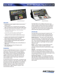
1
Pub. 43004-013H GAI-TRONICS® CORPORATION A HUBBELL COMPANY CommandPLUS Series Desktop Console Installation and Service Manual GAI-Tronics Corporation 400 E. Wyomissing Ave. Mohnton, PA 19540 USA 610-777-1374 800-492-1212 Fax: 610-796-5954 VISIT WWW .GAI-TRONICS.COM FOR PRODUCT LITERATURE AND MANUALS CONFIDENTIALITY NOTICE This manual is provided solely as an operational, installation, and maintenance guide and contains sensitive business and technical information that is confidential and proprietary to GAI-Tronics. GAI-Tronics retains all intellectual property and other rights in or to the information contained herein, and such information may only be used in connection with the operation of your GAI-Tronics product or system. This manual may not be disclosed in any form, in whole or in part, directly or indirectly, to any third party. COMPUTER SOFTWARE COPYRIGHTS This product contains copyrighted computer programs stored in semiconductor memory. These programs are copyrighted by GAI-Tronics Corporation and may not be reproduced in any form without express written permission from GAI-Tronics. WARRANTY GAI-Tronics warrants for a period of one (1) year from the date of shipment, that any GAI-Tronics equipment supplied hereunder shall be free of defects in material and workmanship, shall comply with the then-current product specifications and product literature, and if applicable, shall be fit for the purpose specified in the agreed-upon quotation or proposal document. If (a) Seller’s goods prove to be defective in workmanship and/or material under normal and proper usage, or unfit for the purpose specified and agreed upon, and (b) Buyer’s claim is made within the warranty period set forth above, Buyer may return such goods to GAI-Tronics’ nearest depot repair facility, freight prepaid, at which time they will be repaired or replaced, at Seller’s option, without charge to Buyer. Repair or replacement shall be Buyer’s sole and exclusive remedy, and the warranty period on any repaired or replacement equipment shall be one (1) year from the date the original equipment was shipped. In no event shall GAI-Tronics’ warranty obligations with respect to equipment exceed 100% of the total cost of the equipment supplied hereunder. The applicability of any such third-party warranty will be determined solely by GAI-Tronics. Services. Any services GAI-Tronics provides hereunder, whether directly or through subcontractors, shall be performed in accordance with the standard of care with which such services are normally provided in the industry. If the services fail to meet the applicable industry standard, GAI-Tronics will, for a period of one (1) year from the date of completion, re-perform such services at no cost to the Buyer. Re-performance of services shall be Buyer’s sole and exclusive remedy, and in no event shall GAI-Tronics’ warranty obligations with respect to services exceed 100% of the total cost of services provided hereunder. Limitations/Exclusions. The warranty on any equipment supplied hereunder is subject to Customer’s use in compliance with applicable FCC regulations and manufacturer specifications. The warranties herein shall not apply to, and GAI-Tronics shall not be responsible for, any damage to the goods or failure of the services supplied hereunder, to the extent caused by accident, misuse, abuse, neglect, system design, product modification, failure to follow instructions contained in the product manual, repair, or attempted repair by anyone not authorized by GAI-Tronics, improper installation, installation of parts that do not conform to the quality or specifications of the original parts or accessories, damage or loss occurred during shipment, or any unit which is not new when sold or upon which the serial number has been defaced, modified or removed. The warranty does not extend to damage incurred by natural causes including Force Majeure. The warranty does not cover microprocessors if failure is due to static damage or application of improper voltage. THE WARRANTIES AND REMEDIES CONTAINED HEREIN ARE IN LIEU OF AND EXCLUDE ALL OTHER WARRANTIES AND REMEDIES, WHETHER EXPRESS OR IMPLIED BY OPERATION OF LAW OR OTHERWISE, INCLUDING ANY WARRANTIES OF MERCHANTABILITY OR FITNESS FOR A PARTICULAR PURPOSE. Operational and Maintenance Procedures. Buyer acknowledges that any improper use, maintenance, or modification of the equipment provided hereunder, or use of unqualified maintenance or service technicians will severely impair the operational effectiveness of the entire communication system. Buyer hereby agrees to indemnify, defend and hold GAITronics harmless from and against any and all third party claims arising, in any manner, out of: (a) Buyer’s neglect of the equipment; (b) Buyer’s use of technicians not authorized by GAI-Tronics to service the equipment; or (c) Buyer’s improper use or modification of the equipment or failure to follow the operational and maintenance procedures provided with the equipment. Limitation of Liability/Damages. In no event (even should circumstances cause the exclusive warranties and remedies set forth in the “Warranty” section to fail of their essential purpose) shall either party be liable for any indirect, incidental, special or consequential damages (including, but not limited to, loss of use, loss of anticipated profits, or damages arising from delay) whether such claims are alleged to have arisen out of breach of warranty, breach of contract, strict or absolute liability in tort, or other act, error or omission, or from any other cause whatsoever, or any combination of the foregoing. “Motorola”, “STAT-ALERT”, and “RapidCall” are registered Trademarks of Motorola Corporation. 04/15 Publication 43004-013H i Table of Contents FOREWORD ............................................................................................................................................................... 1 SCOPE OF MANUAL .................................................................................................................................................... 2 NOMENCLATURE ........................................................................................................................................................ 2 ORDERING REPLACEMENT PARTS .............................................................................................................................. 2 SERVICE AND REPAIR ................................................................................................................................................. 2 SAFE HANDLING OF CMOS INTEGRATED CIRCUIT DEVICES ...................................................................................... 3 FEATURES OF THE COMMANDPLUS SERIES DESKTOP CONSOLE ............................................................................... 4 MODEL CHART ........................................................................................................................................................... 5 SPECIFICATIONS ......................................................................................................................................................... 7 DESCRIPTION............................................................................................................................................................ 9 GENERAL DESCRIPTION.............................................................................................................................................. 9 Tone Remote Control ............................................................................................................................................ 9 DC Remote Control............................................................................................................................................. 10 E&M Remote Control ......................................................................................................................................... 10 INSTALLATION ....................................................................................................................................................... 11 GENERAL CONSIDERATIONS ..................................................................................................................................... 11 MECHANICAL RECEIPT INSPECTION ......................................................................................................................... 11 FCC INTERFERENCE WARNINGS .............................................................................................................................. 11 EQUIPMENT REQUIRED ............................................................................................................................................. 11 CABLE INSTALLATION SAFETY CONSIDERATIONS..................................................................................................... 11 TELEPHONE LINE LIGHTNING AND OVER-VOLTAGE PROTECTION............................................................................. 11 LINE CONNECTIONS.................................................................................................................................................. 12 LINE LEVEL SETTINGS .............................................................................................................................................. 13 Line Input (Receive Audio) Level Adjustment ..................................................................................................... 13 Desktop Console Adjustment ........................................................................................................................................... 13 Line Output (Transmit) Level Adjustment ........................................................................................................... 13 TYPES OF BASE STATION CONTROL ......................................................................................................................... 14 INSTALLATION .......................................................................................................................................................... 15 Electrical Interface ............................................................................................................................................. 15 Ground Cable ..................................................................................................................................................... 16 Channel Interface Cable ..................................................................................................................................... 16 Power Supply (3308-00124-00) .......................................................................................................................... 16 Battery Revert Power Supply (XCP0080A)......................................................................................................... 16 ACCESSORIES ........................................................................................................................................................... 17 XGM003A Gooseneck Microphone/ XDM003A Desk Microphone .................................................................... 17 Other Microphones ............................................................................................................................................. 17 XCP0140A Headset Interface Box ...................................................................................................................... 18 Headset/Handset Connection.............................................................................................................................. 19 XFS002A Footswitch .......................................................................................................................................... 20 System Jumper Table .......................................................................................................................................... 21 CARD SUITE PROGRAMMING SOFTWARE .................................................................................................... 23 GENERAL DESCRIPTION............................................................................................................................................ 23 Connections ........................................................................................................................................................ 23 Installation .......................................................................................................................................................... 23 CONSOLE DIAGNOSTICS ..................................................................................................................................... 25 ENTERING THE DIAGNOSTIC MODE .......................................................................................................................... 25 USER PARAMETERS MENU ....................................................................................................................................... 26 Side Tone Volume Adjust .................................................................................................................................... 26 Microphone Selection and Sensitivity ................................................................................................................. 27 Printer Error Messages ...................................................................................................................................... 28 CLOCK AND DISPLAY SET......................................................................................................................................... 28 Setting the Clock ................................................................................................................................................. 29 04/15 Publication 43004-013H ii Table of Contents CommandPLUS Series Desktop Console Installation and Service Manual Setting the Display Viewing Angle ...................................................................................................................... 29 Setting the Display Brightness ............................................................................................................................ 30 SERVICE DIAGNOSTICS ............................................................................................................................................. 30 Keyboard Diagnostics......................................................................................................................................... 31 Keyboard Test .................................................................................................................................................................. 31 LED Test .......................................................................................................................................................................... 31 Audio Diagnostic ................................................................................................................................................ 32 Test 1 – Communications Test ......................................................................................................................................... 32 Test 2 – Audio Loop Test ................................................................................................................................................. 32 Test 3 – Output Adjust ..................................................................................................................................................... 32 Test 4 – Gain Stage Test................................................................................................................................................... 32 Test 5 – Input Level Adjust .............................................................................................................................................. 32 Internal Diagnostics ........................................................................................................................................... 33 Alert Level ........................................................................................................................................................... 33 Page Level .......................................................................................................................................................... 33 Security ............................................................................................................................................................... 33 START-UP DISPLAY .................................................................................................................................................. 34 Boot-Up Error Code Definitions......................................................................................................................... 34 Code Definitions ................................................................................................................................................. 34 CARD Suite Software Version............................................................................................................................. 34 Firmware Version – Host – DSP – Display CPK ............................................................................................... 34 FEATURES AND OPTIONS.................................................................................................................................... 35 DTMF DECODE ....................................................................................................................................................... 35 PAGING ENCODE ...................................................................................................................................................... 35 POSITIVE MODE CONTROL ....................................................................................................................................... 35 PRINTER INTERFACE................................................................................................................................................. 36 LOGGING RECORDER OUTPUT MODULE ................................................................................................................... 37 DC CONTROL CP0010A/XCP0010A ....................................................................................................................... 38 Installation/Relocation........................................................................................................................................ 38 4-CHANNEL E&M CONTROL CP0040A/XCP0040A ................................................................................................ 40 SUPERVISORY CONTROL CP0050A/XCP0050A ...................................................................................................... 40 DIRECT ENHANCED FULL DUPLEX PHONE INTERFACE CP0070/XCP0070A............................................................ 41 Ring Detect Sensitivity ........................................................................................................................................ 41 EXTERNAL ENHANCED FULL DUPLEX PHONE INTERFACE CP0060/XCP0060A ...................................................... 41 BATTERY REVERT XCP0080A................................................................................................................................. 41 MDC1200 STAT-ALERT SIGNALING CP0650/TDN9413A ................................................................................... 41 25-PAIR TELCO INTERFACE XCP0030A .................................................................................................................. 42 BUTTON/ELASTOMER REPLACEMENT (XCP0110A) ................................................................................................ 44 PAGING ..................................................................................................................................................................... 45 TYPES OF PAGING..................................................................................................................................................... 45 2-TONE PAGING ....................................................................................................................................................... 45 2-Tone Paging Example...................................................................................................................................... 45 Group Call .......................................................................................................................................................... 46 PLECTRON PAGING ................................................................................................................................................... 49 Plectron Paging Example ................................................................................................................................... 49 5/6-TONE PAGING .................................................................................................................................................... 51 5/6 Tone Paging Example ................................................................................................................................... 51 TROUBLESHOOTING ............................................................................................................................................ 53 TROUBLESHOOTING THE COMMANDPLUS SERIES DESKTOP CONSOLE ................................................................... 53 REPLACEMENT PARTS LIST ...................................................................................................................................... 54 MAIN CIRCUIT BOARD ........................................................................................................................................ 55 DEFINITIONS AND ACRONYMS ......................................................................................................................... 57 04/15 Publication 43004-013H iii Foreword User Instructions (USA) This equipment complies with Part 68 of the FCC rules and the requirements adopted by the ACTA. On this equipment is a label that contains, among other information, a product identifier in the format US:AAAEQ##TXXXX. If requested, this number must be provided to the telephone company. A plug and jack used to connect this equipment to the premises wiring and telephone network must comply with the applicable FCC Part 68 rules and requirements adopted by the ACTA. A compliant telephone cord and modular plug is provided with this product. It is designed to be connected to a compatible modular jack that is also compliant. See installation instructions for details. The REN is used to determine the number of devices that may be connected to a telephone line. Excessive RENs on the telephone line may result in the devices not ringing in response to an incoming call. In most but not all areas, the sum of the RENs should not exceed five (5.0). To be certain of the number of devices that may be connected to a line, as determined by the total RENs, contact the local telephone company. For products approved after July 23, 2001, the REN for this product is part of the product identifier that has the format US:AAAEQ##TXXXX. The digits represented by ## are the REN without a decimal point (e.g., 03 is an REN of 0.3). For earlier products, the REN is separately shown on the label. If this equipment [GAI-Tronics telephone] causes harm to the telephone network, the telephone company will notify you in advance that temporary discontinuance of service may be required. But if advance notice isn’t practical, the telephone company will notify the customer as soon as possible. Also, you will be advised of your right to file a complaint with the FCC if you believe it is necessary. The telephone company may make changes in its facilities, equipment, operations, or procedures that could affect the operation of the equipment. If this happens the telephone company will provide advance notice in order for you to make necessary modifications to maintain uninterrupted service. If trouble is experienced with this equipment, please contact GAI-Tronics Corporation at 800-492-1212 or www.gaitronics.com for repair or warranty information. If the equipment is causing harm to the telephone network, the telephone company may request that you disconnect the equipment until the problem is resolved. Connection to party line service is subject to state tariffs. Contact the state public utility commission, public service commission or corporation commission for information. This equipment uses a telephone handset and it is hearing aid compatible. User Instructions (Canada) CP-01, Issue 8, Part I: Section 14.1 NOTICE: The Industry Canada label identifies certified equipment. This certification means that the equipment meets certain telecommunications network protective, operational and safety requirements as prescribed in the appropriate Terminal Equipment Technical Requirements document (s). The Department does not guarantee the equipment will operate to the user’s satisfaction. Before installing this equipment, users should ensure that it is permissible to be connected to the facilities of the local telecommunications company. The equipment must also be installed using an acceptable method of connection. The customer should be aware that compliance with the above conditions may not prevent degradation of service in some situations. Repairs to certified equipment should be coordinated by a representative designated by the supplier. Any repairs or alterations made by the user to this equipment, or equipment malfunctions, may give the telecommunications company cause to request the user to disconnect the equipment. Users should ensure for their own protection that the electrical ground connections of the power utility, telephone lines and internal metallic water pipe system, if present, are connected together. This precaution may be particularly important in rural areas. CAUTION Users should not attempt to make such connections themselves, but should contact the appropriate electric inspection authority, or electrician, as appropriate. CP-01, Issue 8, Part I: Section 14.2 NOTICE: The Ringer Equivalence Number (REN) assigned to each terminal device provides an indication of the maximum number of terminals allowed to be connected to a telephone interface. The termination on an interface may consist of any combination of devices subject only to the requirement that the sum of the Ringer Equivalence Numbers of all the devices does not exceed 5. 1 04/15 Foreword CommandPLUS Series Desktop Console Installation and Service Manual Scope of Manual This manual offers descriptive data and service information for the Command PLUS Series Desktop Console. Service diagrams and printed circuit board details are a part of this service manual. The Command PLUS Series Desktop Console Operator’s Manual, 43004-016, is another publication related to the operation of the CommandPLUS Series Console. Both manuals are available on our website at www.gai-tronics.com. Programming instructions are included with the GAI-Tronics CARD Suite Software. The software must be registered with GAI-Tronics in order to receive future updates. Nomenclature The model number, located on the nameplate on the bottom, specifically identifies GAI-Tronics equipment. The console version is displayed on the screen. Options, program software version, and firmware versions are also displayed. If additional options are ordered, the option will be identified on the circuit board. Ordering Replacement Parts When ordering replacement parts or requesting equipment information, please include the complete identification number. This applies to all components, kits, and chassis. If the component part number is not known, the order should include the number of the chassis or kit of which it is a part and sufficient description of the desired component to identify it. Order parts from: Customer Service GAI-Tronics Corporation 400 E. Wyomissing Ave. Mohnton, PA 19540 US: 800-492-1212 Outside US: 610-777-1374 Service and Repair Inoperative or malfunctioning equipment should be returned to the factory for repair. Please call 1-800-492-1212 to obtain a Return Authorization number, published repair prices, and shipping instructions. A Return Authorization number can also be obtained by visiting our website at www.gai-tronics.com. NOTE: A purchase order or credit card number is required prior to processing non-warranty repairs. 04/15 2 CommandPLUS Series Desktop Console Installation and Service Manual Foreword Safe Handling of CMOS Integrated Circuit Devices Many of the integrated circuit devices used in communications equipment are of the Complementary Metal Oxide Semiconductor (CMOS) type. Because of their high open circuit impedance, CMOS integrated circuits are vulnerable to damage from static charges. Care must be taken handling, shipping, and servicing them and the assemblies in which they are used. Even though protection devices are provided in CMOS integrated circuit inputs, the protection is effective only against over-voltage in the hundreds of volts range such as is encountered in an operating system. In a system, circuit elements distribute static charges and load the CMOS circuits, decreasing the chance of damage. However, CMOS circuits can be damaged by improper handling of the modules, even in a system. To avoid damage to circuits, observe the following handling, shipping, and servicing precautions: 1. Prior to and while servicing a circuit module, particularly after moving within the service area, momentarily touch both hands to a bare metal, earth-grounded surface. This will discharge any static charge that may have accumulated on the person doing the servicing. NOTE: Wearing a conductive wrist strap will minimize static build-up during servicing. 2. Whenever possible, avoid touching any electrically conductive parts of the circuit module with your hands. 3. Power down the unit before installing or removing the circuit module. 4. When servicing a circuit module, avoid carpeted areas, dry environments, and certain types of clothing (silk, nylon, etc.) because they contribute to static build-up. Similarly, disconnect the test probe prior to removing the ground lead. 5. All electrically powered test equipment should be grounded. Apply the ground lead from the test equipment to the circuit module before connecting the test probe. 6. If a circuit module is removed from the system, it is desirable to lay it on a conductive surface (such as a sheet of aluminum foil) which is connected to ground through 100k of resistance. 7. When soldering, be sure the soldering iron is grounded, and has a grounded tip. 8. Prior to connecting jumpers, replacing circuit components, or touching CMOS pins (if this becomes necessary in the replacement of an integrated circuit device), be sure to discharge any static build-up as described in procedure 1. Since voltage differences can exist across the human body, it is recommended that only one hand be used if it is necessary to touch pins on the CMOS device and associated board wiring. 9. When replacing a CMOS integrated circuit device, leave the device in its conductive rail container or conductive foam until it is to be inserted into the printed circuit module. 10. All low impedance test equipment (such as pulse generators, etc.) should be connected to CMOS device inputs after power is applied to the CMOS circuitry. Similarly, such low impedance equipment should be disconnected before power is turned off. 11. Replacement modules shipped separately from the factory will be packaged in a conductive material. Any modules being transported from one area to another should be wrapped in a similar material (aluminum foil may be used). Never use non-conductive material for packaging these modules. 3 04/15 Foreword CommandPLUS Series Desktop Console Installation and Service Manual Features of the CommandPLUS Series Desktop Console Enhanced multi-tasking operation Available in 4-, 8-, and 12-channel control. The 4- and 8-channel consoles are field expandable. Accommodates a maximum of 10 consoles per system Supports Tone, DC, and E&M control types Includes Paging Encoder for individual, sequential multi-channel group, stack paging, and one-touch paging DTMF Decode for Automatic Number Identification 16-Frequency control per channel Optional MDC1200 STAT-ALERT Signaling capability 24 programmable buttons allocated as two per channel to support channel functions such as alert tone, frequency change, infinite or timed mute, monitor and supervisor as well as one-touch paging using preprogrammed aliases Optional full-duplex telephone interface capability Supports headset, desktop microphone, and footswitch Allows standard PC applications to capture printer port output for logging Individual master volume controls for select and unselect speakers Individual select and unselect volumes per channel Easy-to-use Windows®-based programming application VU-meter for receive and transmit audio Logging recorder output Custom paging and multiple alert tones (4) 12/24-hour clock 04/15 4 CommandPLUS Series Desktop Console Installation and Service Manual Foreword Model Chart The following is a list of the CommandPLUS Series Desktop Console models: Table 1. Model Description ICP9004A CommandPLUS Series 4-Channel Desktop Console (expandable) ICP9008A CommandPLUS 8-Channel Desktop Console (expandable) ICP9012A CommandPLUS 12-Channel Desktop Console The following options can be ordered pre-installed in your CommandPLUS Series Console: Table 2. Option Description CP0010 DC Control (Order one for each dc channel) CP0040 E&M Signaling (requires CP0050) CP0050 Supervisory Control CP0060 External Enhanced Full Duplex Phone Interface CP0650 MDC STAT-ALERT Signaling (replaces logging recorder output capability) CP0070 Direct Enhanced Full Duplex Phone Interface The following features are included in the standard console and are available through either programming selection or direct access: DTMF Decode Positive Mode Control Paging Encode Multi-Select Option Logging Recorder Output 16-Frequency Control 5 04/15 Foreword CommandPLUS Series Desktop Console Installation and Service Manual The following field installation kits are available for installation in the CommandPLUS Series Desktop Console: Table 3. Kit Description XCP0010A DC Control Kit XCP0020A 16-Frequency Capable Kit (existing installation upgrade) XCP0030A 25-Pair Telco Interface Kit XCP0040A 4-Channel E&M Signaling Kit (requires CP0050 or XCP0050A) XCP0050A Supervisory Control Kit XCP0060A External Enhanced Phone Interface Kit XCP0070A Direct Enhanced Phone Interface Kit XCP0080A Battery Revert Power Supply Kit XCP0100A 4-Channel Expansion Kit XCP0110A Replacement Button/Elastomer Kit XCP0140A Headset Box XCP0150A 25-foot cable, 25-pair with connector XCP0160A 50-foot cable, 25-pair with connector XGM003A Gooseneck Mic XHS003C Amplified Headset (requires XCC003B) XCC003C Coiled Cord with PTT (requires XCP0140A) XDM002A Desk Mic XDM003A Gooseneck Desk Mic XFS002A Dual Footswitch TDN9413A MDC1200 STAT-ALERT Signaling Kit The following programming software and cable are required for programming the CommandPLUS Series Desk Console: Table 4. Model Description XAC4000B Programming Bundle Flash Drive; Includes CARD Suite Software (included with console purchase) XCP0170A Programming Cable 04/15 6 CommandPLUS Series Desktop Console Installation and Service Manual Foreword Specifications General Temperature range .................................................................................................................. 0º C to +50º C Humidity ................................................................................................................................... 95% at 50º C Physical size ................................................................................................ 9.5 H 14.5 W 13.5 D inches Power input ................................................................... 120/240 V ac, 15% (47–63 Hz); or +10.5–18 V dc Weight (without options) ................................................................................................................................ ICP9004A ................................................................................................................................... 18.0 lbs. ICP9008A ................................................................................................................................... 19.5 lbs. ICP9012A ................................................................................................................................... 21.0 lbs. Audio General Audio response ....................................................................................................... +3 dB at 300 to 3000 Hz Hum and noise ............................................................. Transmit – Less than 50 dB below full rated power Receive – Less than 55 dB below full rated power Audio distortion .............................................................................................................. Less than 2% THD Compression ....................................................................................... Normalizes input variations of 30 dB Receiver Audio Input ........................................................................................................... −25 dBm to +11 dBm adjustable Crosstalk ............................................................... 60 dB below rated output levels at rated line impedance Input impedance ............................................................................................................... 600 ohms nominal Tone Remote Control Guard tone............................................................................... 2100, 2175, 2325, 2800 (default = 2175 Hz) Function tones ............................................................................................................ F1 Transmit: 1950 Hz F2 Transmit: 1850 Hz F3 Transmit: 1350 Hz F4 Transmit: 1250 Hz Monitor: 2050 Hz Function tones are selectable via GAI-Tronics’ CARD Suite Software Application Transmit Audio Condenser microphone ......................................................................... Selectable, digital steps 1 through 5 Microphone sensitivity ......................................... Reference 165 mV, selectable, digital steps 1 through 5 Audio out to phone line ................................................................ −20 dBm to +11 dBm into 600-ohm load Line balance ....................................................................................................................... 70 dB at 1000 Hz DC Remote Control Audio out to phone line ............................................................................................ F1 Transmit: +5.5 mA F2 Transmit: +12.5 mA Monitor: −2.5 mA Output currents are selectable via GAI-Tronics’ CARD Suite Software Application 7 04/15 Foreword CommandPLUS Series Desktop Console Installation and Service Manual FCC Information FCC Registration Number ....................................................................................... US: ADGOT01B46053 Ringer Equivalence Number (REN) ......................................................................................................... . .1 Network connection (USOC)................................................................................................................. RJ11 IC Information (Canada) IC Certification Number .............................................................................................................. 8226048 A Ringer Equivalence Number (REN) ......................................................................................................... . .1 Connecting method ............................................................................................................................ CA11A 04/15 8 Description General Description The CommandPLUS Series Desktop Console is a multi-channel console compatible with conventional radio systems. It uses tone remote control to interact with the base stations, but dc remote control and E&M control are available as options. The CommandPLUS Series Console allows control of up to 12 individual base stations. Operating parameters are programmed via the console’s CARD (Configuration Application for Radio Dispatch) Suite Software Application, found in the No. XAC4000B Programming Bundle Flash Drive. Tone Remote Control Tone control is a particular scheme of remote radio control. This scheme uses tones of different frequencies and levels to command the radio to perform various tasks. Control tones are categorized as high level guard tone, function tone, or low level guard tone. These tones are generated by the console and routed to the base stations via wire line connections (leased or owned dry lines). High level guard tone precedes all control tone sequences and notifies the selected base station of a change in its operating mode. High level guard tone is normally active for 120 ms, but the duration is programmable from 120 to 4000 ms in 10-ms increments. Refer to Figure 1. Following the high level guard tone is function tone. Function tone is normally active for 40 ms, but the duration is programmable between 40 and 4000 ms in 10 ms increments. It forces the radio to perform a task specified by the tone’s frequency. Low level guard tone follows function tone and remains active as long as the base station is transmitting. Low level guard tone is present only when the tone control sequence is a command that causes the radio to transmit. Figure 1. Tone Remote Control Tones 9 04/15 Description CommandPLUS Series Desktop Console Installation and Service Manual DC Remote Control DC control is a method of remote radio control. This scheme uses dc currents of differing magnitudes and polarities to command the radio to perform various tasks. The dc control currents are directly impressed upon the audio wire line connections between the console and base stations. E&M Remote Control E&M remote control is another scheme of remote radio control. This scheme uses two pair of leads to control communication between the console and base station. The console uses the “M” leads to signal the base station when to transmit, and uses the “E” leads to detect when to receive. 04/15 10 Installation General Considerations The CommandPLUS Series Desktop Console can be placed on any flat level surface (desk top) that provides the operator with full visibility of all front panel controls and indicators. Mechanical Receipt Inspection The CommandPLUS Series Desktop Console is shipped in a cardboard container with inserts. Thoroughly inspect it as soon as possible after delivery. In-transit damage should be immediately reported to the transportation company. FCC Interference Warnings The FCC requires that manuals pertaining to Class A and Class B computing devices contain warnings about possible interference with local and residential radio and TV reception. Please read these warnings and all safety information in the “Foreword” section of this manual. Equipment Required Test Equipment RF service monitor RMS responding ac voltmeter with dB ranges for measuring audio levels #1 Phillips screwdriver 1/8-inch flat blade screwdriver Documentation Base station’s tone remote adapter manual These installation instructions Cable Installation Safety Considerations Interconnecting, communications, and Class 2 dc power cables should be separated from electrical light or other Class 1 circuits by at least 2 inches. The exception is where Class 1 wiring or power circuits are run in a raceway, or are metal-sheathed or metal-clad, or are permanently separated from the conductors of the other circuitry by a continuous and firmly fixed nonconductor such as porcelain tubes or flexible tubing in addition to the insulation on the wire. Communications cables and in-building wiring should be listed and marked for the purpose according to NEC Article 800. Telephone Line Lightning and Over-voltage Protection The CommandPLUS Series Console has an over-current phone line fuse which protects against occasional extreme fault conditions that may get past the primary protectors. An example of such a fault condition is a power line cross. For maximum surge and lightning protection, building primary (overvoltage) protectors should be installed at the point where the telephone lines enter the radio equipment building. Primary protectors are usually required by local codes and should be provided by your leased line provider. 11 04/15 Installation CommandPLUS Series Desktop Console Installation and Service Manual Line Connections Line Considerations - Private Circuit If leased lines from your local telephone company are used between the console and a tone remote adapter or base station, the telephone company (Local Exchange Carrier) may request a Facility Interface Code (FIC). The FIC is subject to local availability. See Table 5. Table 5. Analog Facility Interface Code FIC Description 02NO2 2-wire private line; no signaling conversion by LEC (IN-Band) 02NO4 4-wire private line; no signaling conversion by LEC (IN-Band) Metallic 2 or 4-wire metallic private line (“Hoot and Holler” circuits) Within a manufacturing plant, a campus, or large building, customer-supplied metallic pairs may be used. It is not necessary to have dc continuity on these lines. While using tone control, continuity is required for dc control. Circuit Conditioning The console is designed to work with good quality analog speech band or leased private circuit. This was previously known as ‘basic’ conditioning under Series 2000/3002 service. The line must be non-PSTN (no dial tone, talk-battery, or signaling). This equipment falls under the Category II, FCC Tariff #260 Service and is exempt from FCC Part 68 registration. (Ref. FCC Form 730 Application Guide pages 1– 5.) For 2-wire operation, 2000 Series lines may be used with or without conditioning. C1 or C2 conditioning is available for these lines and relates to the envelope delay distortion and attenuation. A basic conditioned line may be used if it is the only type available. Overall system quality is limited by the quality of these lines. 04/15 12 CommandPLUS Series Desktop Console Installation and Service Manual Installation Line Level Settings The CommandPLUS Desktop Console allows the installer to adjust level settings through the on-screen diagnostics. These procedures assume that the base stations have been properly adjusted. Line Input (Receive Audio) Level Adjustment The line input level adjustment allows the receive audio of each channel to be compensated for line loses between the base station and console, ensuring optimum audio performance of the console. It is important to set this level properly as maladjustment can cause distortion or over-compression of the receive audio. 1. Adjust the base station receive audio level to the console by applying an RF signal modulated with a 1000 Hz tone at rated system deviation to the base station receiver. 2. Adjust the base station output control for the desired level (e.g. –10 dBm) to the audio control line. Do not exceed the line supplier’s recommended maximum operating level. Desktop Console Adjustment 1. Connect an ac voltmeter, or other appropriate measuring device, across the receive audio pair of the console MCU according to Table 9. Make a note of the measurement. 2. Enter the Navigator Diagnostics. Select SERVICE DIAGNOSTICS, then AUDIO. Enter the password 1490, and select INPUT LEVEL. 3. Use the channel VOL Up/Down buttons to select the proper input level settings. The level can be changed in 3-dB increments. Select the setting that is closest to, but not higher than, the measured level. For example, if the measured level is –11 dB, the console should be set at a –12 dB input sensitivity setting. 4. Repeat this process for each channel. 5. Press the MODE button when the setting is complete. When prompted, press 1 to save, or 2 to abandon changes. Line Output (Transmit) Level Adjustment The output of each channel can be adjusted to accommodate for line losses from the console to the base station. Adjustment of the line out should be similar to that of the line input adjustment where the audio level at the base station is measured while the output level of the console is adjusted to achieve the optimum audio level at the base station. 1. Connect an ac voltmeter, or other appropriate measuring device, across the transmit audio pair at the base station. Refer to Table 9 for the correct test connections. 2. Enter the Navigator Diagnostics. Select SERVICE DIAGNOSTICS, then AUDIO. Enter the password 1490, and select OUTPUT ADJUST. 3. The MCU will produce a 2175 Hz signal output on all channel audio pairs. Refer to Table 9 for the correct connections. 4. Use the channel VOL Up/Down buttons to raise or lower the output level of the MCU channel. 5. Repeat this process for each channel. 6. Press the MODE button when complete. When prompted, press 1 to save, or 2 to abandon changes. 13 04/15 Installation CommandPLUS Series Desktop Console Installation and Service Manual Types of Base Station Control The CommandPLUS Console is capable of either tone or dc control depending on the position of jumpers JU620 through JU623. For dc control, the console must have option CP0010 or XCP0010. Refer to Table 6. Table 6. Jumper Positions for DC or Tone Control Selection Function Jumper No. Position Ch. 1, 5, 9 JU620 IN OUT Tone Control DC Control (option CP0010 or XCP0010) Ch. 2, 6, 9 JU621 IN OUT Tone Control DC Control (option CP0010 or XCP0010) Ch. 3, 7, 11 JU622 IN OUT Tone Control DC Control (option CP0010 or XCP0010) Ch. 4, 8, 12 JU623 IN OUT Tone Control DC Control (option CP0010 or XCP0010) NOTE: If operating in dc mode, the console must also be programmed for dc under Type of Interface in the CARD Software. Two Wire Control (default) In this configuration, a single two-wire line is used to carry the control tones or dc control currents (as applicable per channel) and the transmitter audio, from the CommandPLUS Series Console to the base station. This same 2-wire line is used to return the receive audio back to the console from the base station. Refer to Table 7 for the appropriate system configuration. Four Wire Audio/Control In this configuration, one pair of lines is used to carry both control tones or dc control currents (as applicable per channel) and the transmitter audio from the CommandPLUS Series Console to the base station. The other pair is used to carry the receive audio from the base station back to the console. Refer to Table 7 for the appropriate system configuration. NOTE: In this configuration, RX audio can still be received on original 2-wire pair. Table 7. Slave Module – 2-Wire/4-Wire Function Jumper No. Position Ch. 1, 5, 9 – 2W/4W Select JU602 2W – 2 wire control 4W – 4 wire control Ch. 2, 6, 9 – 2W/4W Select JU606 2W – 2 wire control 4W – 4 wire control Ch. 3, 7, 11 – 2W/4W Select JU610 2W – 2 wire control 4W – 4 wire control Ch. 4, 8, 12 – 2W/4W Select 04/15 JU614 14 2W – 2 wire control 4W – 4 wire control CommandPLUS Series Desktop Console Installation and Service Manual Installation Installation The electrical hook-up of the console requires these basic connections: the ground wire, one to three channel interface cables, and the power supply cable. WARNING Voltages hazardous to life may be present at the exposed control line terminals under certain conditions during the following procedures. These voltages are also present on some component leads. Care should be taken to avoid shock during installation. Electrical Interface All of the electrical connections to the console are made at the rear panel. Power to the console is furnished through a 5-pin, DIN connector, P5. The Figure 2 shows the rear view of the CommandPLUS Series Desktop Console and the locations of the various connectors. CHANNELS 9-12 CHANNELS 5-8 POWER STATUS LED CHANNELS 1-4 LOGGING OUTPUT TELEPHONE INTERFACE RS232 CONNECTOR FOOT SWITCH MIC RESET HEADSET HANDSET Figure 2. View of CommandPLUS Back Panel with Connectors The pinout for the power DIN connector is shown in Table 8: Table 8. Power DIN Connector Pinout Pins Function 1, 4 B-, Batt-, GND tab 3, 5 B+, IN 2 Batt+ 1 3 4 5 2 Figure 3. Power Connector Pinout 15 04/15 Installation CommandPLUS Series Desktop Console Installation and Service Manual Ground Cable The CommandPLUS Series Desktop Console is designed with a high degree of protection against electrostatic discharge (ESD), power line surges and telephone line surges. The protection circuitry is designed to shunt the transient current to earth ground through the GND terminal, located on the back panel of the console. This terminal must be connected to a high quality earth ground in order to obtain maximum protection. NOTE: This ground should be connected through a utility entrance ground cable and the telephone entrance ground cable, if different from the utility ground. Lightning is essentially RF, and as such does not like long leads or sharp bends. Make connections appropriately. Channel Interface Cable A 12-pair interface cable (one supplied for each four channels of operation) plugs into the 25-pin D-connectors on the back of the console. Refer to Figure 2 showing the rear view of the console. The ICP9004A 4-channel console employs only one 25-pin D-connector-cable assembly for connections to the base station(s) control and audio pairs, generally through a termination block or connector. Refer to Table 9 for wire colors and pin functions. Table 9. Channel Interface Connectors and Cable Colors Channel No. Pin No. Wire Colors Pin Function 1 5 9 14 15 1, 2 White/Blue Blue/White White/Orange, Orange/White TX Audio + /RX 2-Wire TX Audio – /RX 2-Wire RX Audio 4-Wire 2 6 10 3 4 5, 6 White/Green Green/White White/Brown, Brown/White TX Audio + /RX 2-Wire TX Audio – /RX 2-Wire RX Audio 4-Wire 3 7 11 8 9 10, 11 White/Gray Gray/White Red/Blue, Blue/Red TX Audio + /RX 2-Wire TX Audio – /RX 2-Wire RX Audio 4-Wire 4 8 12 12 13 24, 25 Red/Orange Orange/Red Red/Green, Green/Red TX Audio + /RX 2-Wire TX Audio – /RX 2-Wire RX Audio 4-Wire Some installations can use the optional CP0030A 25-pair Telco Interface Option, or the XCP0030A 25-pair Telco Interface Option Field Installation Kit, when the telephone company supplies a 50-pin standard USOC, RJ21X Telephone Connector. Power Supply (3308-00124-00) The CommandPLUS Series Desktop Console uses an external power supply provided with the unit. This is a self-contained unit that can be positioned on the desk with the console or located at some other convenient spot. It requires an input of 90-264 V ac 50-60 Hz and delivers a regulated output of 12 V dc at 4.2 A maximum. Battery Revert Power Supply (XCP0080A) The relay and associated devices for battery revert are incorporated on the main printed circuit board. This option includes a modified power supply. 04/15 16 CommandPLUS Series Desktop Console Installation and Service Manual Installation Accessories XGM003A Gooseneck Microphone/ XDM003A Desk Microphone These heavy-duty microphones connect directly to the RCA connector labeled MIC on the rear of the console. The console-adapted gooseneck microphone mounts to the right or left side of the console. If right-hand mounting is required, relocate the base mounting bracket to its other slot. Use the following procedure to install the microphone. 1. Lay the console on its side and locate the two threaded mounting holes. 2. Fasten the bracket of the gooseneck microphone to these holes using the two 10-32 ¼-inch screws provided. 3. Insert the microphone plug into the mic jack (labeled MIC) at the back of the console. 4. Complete the installation by routing the microphone cable along the bottom of the console housing and fasten it into position with adhesive mounting tie-wraps. No jumper settings are required. Refer to the “User Parameters Menu” section of this manual on page 26 for required microphone selection and level settings. (The console normally defaults to its built-in condenser microphone.) Other Microphones The rear panel connector (MIC) is normally provided to support the external gooseneck style microphone, Model XGM003A or XDM003A Desktop Microphone. For higher level microphones requiring an operating bias such as an Electret condenser microphone, install jumper JU6 to provide the operating bias and jumper JU5 to reduce the gain of the microphone pre-amp. Refer to Figure 4 below for the board position of JU5 and JU6. The default for these jumpers is OUT. Figure 4. Main Board Microphone Jumper Positions 17 04/15 Installation CommandPLUS Series Desktop Console Installation and Service Manual XCP0140A Headset Interface Box The interface box allows the use of several headset accessories, such as the Startset II, Supra headband-style monaural headset, and Supra headband-style noise-canceling headset. The headset jack is assembled for mounting on the right-hand side of the console. Its use requires proper jumper installation. (See Figure 4 for jumper locations.) If left-hand mounting is required, reverse the assembly. The headset plugs into the modular-style headset jack (labeled HEADSET/HANDSET) on the rear panel. See Table 10 for the headset modular jack pinout. 1. Verify the correct placement of the 2-position row jumpers PP1 and PP2. 2. Referring to Figure 4 for the programming jumpers on the main board, locate the 3 rows of jumpers marked PP2, PP1 (center) and PP3. 3. Position the shorting clip from PP1 to PP2 to enable operation of the headset. This option must also be enabled and the sensitivity of the headset microphone set in the User Parameters Menu as described in the “Console Diagnostics” section. Refer to Table 10 for the headset jack pinout. Table 10. Headset 8-pin Modular Jack (PP1-PP2) Pin No. 04/15 Pin Function 1 TX Lo 2 TX Hi 3 PTT 4 On-hook 5 GND 6 RX Audio 7 PTT Return 8 N/C 18 CommandPLUS Series Desktop Console Installation and Service Manual Installation Headset/Handset Connection An 8-pin modular connector is provided on the rear of the console for connection of the XCP0500A Handset Assembly or XDM002A Low-End Desktop Microphone. (Use of the XDM002A Microphone for console operation is not recommended.) For proper operation, jumpers must be properly installed. 1. Refer to Figure 4 to locate the 2-position jumpers marked PP2, PP1 (center) and PP3. 2. Position the jumpers so that row PP1 is connected to row PP3 for desktop operation. 3. This option must be enabled in the User Parameter Menu. Refer to the “Console Diagnostics” section of this manual for further instructions. Refer to Table 11 for pinout information. Table 11. Headset/Handset Connector Pinout Pin No. Pin Function 1 Logic GND 2 RS-232 Host TX 3 PTT 4 Mic Hi 5 Mic Lo 6 Monitor 7 RS-232 Host RX 8 10 V dc 19 04/15 Installation CommandPLUS Series Desktop Console Installation and Service Manual XFS002A Footswitch This accessory, which provides both hands-free PTT and monitor functions, is provided with a cable fitted with a keyed connector containing three contacts. This connector mates with P7 on the back of the console. Table 12 defines the function of each pin. Table 12. Footswitch – 3-Pin Connector Pin No. Pin Function 1 PTT 2 GND 3 Monitor NOTE If the desk mic or footswitch is connected after the console has been powered up, the console must be powered down and powered up again. This allows the console to read the polarity of the monitor switch. DO NOT press the monitor switch while the console is powering up, or the polarity will be read incorrectly. 04/15 20 CommandPLUS Series Desktop Console Installation and Service Manual Installation System Jumper Table The purpose of Table 13 is to assist the installer in determining the correct placement of console slave board jumpers, for various system configurations. Each CommandPLUS Series Desktop Console is equipped with a minimum of one CSD slave board for ICP9004A (four channels), two slave boards for ICP9008A (eight channels) and three slave boards for ICP9012A (12 channels) operation. Each channel can be individually configured to support 2-wire, 4-wire, bridging, or terminating modes of operation (parallel or single console). Refer to Figure 5. The CommandPLUS Series Desktop Console is shipped with all line termination resistors in place. For parallel operation of multiple consoles, the last console on any particular line should have its 2W or 4W termination jumpers in place and any intermediate console should have the line termination jumpers removed. Table 13. CSD Slave Unit Table Function Ch. 1, 5, 9 Jumper No. 4W RX Termination JU603 IN OUT Ch. 2, 6, 10 4W RX Termination JU607 IN OUT Ch. 3, 7, 11 4W RX Termination JU611 IN OUT Ch. 4, 8, 12 4W RX Termination JU615 IN OUT Ch. 1, 5, 9 Ch. 2, 6, 10 Ch. 3, 7, 11 Ch. 4, 8, 12 TX Source Impedance 2W RX Termination Impedance JU601 TX Source Impedance 2W RX Termination Impedance JU605 TX Source Impedance 2W RX Termination Impedance JU609 TX Source Impedance 2W RX Termination Impedance JU613 IN OUT IN OUT IN OUT IN OUT 21 Position 600 ohm (default) Parked – Bridging Impedance 600 ohm (default) Parked – Bridging Impedance 600 ohm (default) Parked – Bridging Impedance 600 ohm (default) Parked – Bridging Impedance 600 ohm (default) Parked – Bridging Impedance (parallel console) 600 ohm (default) Parked – Bridging Impedance (parallel console) 600 ohm (default) Parked – Bridging Impedance (parallel console) 600 ohm (default) Parked – Bridging Impedance (parallel console) 04/15 Installation CommandPLUS Series Desktop Console Installation and Service Manual The Figure 5 shows the positions on the upper portion of the CSD slave board. Figure 5. 2-Wire/4-Wire Jumper Configuration 04/15 22 CARD Suite Programming Software General Description GAI-Tronics’ CARD Suite Programming Software, included in the No. XAC4000B Programming Bundle Flash Drive, is needed to program some of the functions and parameter settings of the dispatch equipment. This software is provided with the CommandPLUS Console. It allows entry of operational programming data into your personal computer for transfer to the equipment. The programmed data can be retrieved, edited, archived, and printed in hard copy for record keeping. Detailed programming information can be found in CARD Suite’s Help file. The following information is provides as guidance to initiate the programming application. Connections The GAI-Tronics equipment must be connected to your personal computer with the programming cable, part number XAC0170A, before the programming software can be used. To make this connection, attach the cable to the COM1 or COM2 connector on the computer. Connect the other end to the programming jack on the GAI-Tronics equipment. Installation The minimum system requirement necessary to support the CARD Suite Software Application is Windows 95 or newer. However, CARD Suite is not compatible with Windows NT. It is compatible with Windows XP (Home or Professional), Vista, and Windows 7 when used in Virtual Mode. The CARD Suite Programming Application components are contained on No. XAC4000B Flash Drive. Please exit all other programs that are running until the installation is complete. 1. Place the flash drive in the computer’s USB port. Select the START button and then select Run from the Start menu. At the prompt, type x:\software select menu.exe where x represents the drive letter that is associated with your flash drive. A CARD Suite icon should appear on the desktop display after successful installation. 2. After opening the program, select the appropriate product icon, click on File in the toolbar and select New Archive to begin creating an archive. 3. Enter an archive description (name) and customer/site (name), select the method of creating the archive (default values or reading a connected unit), and click Ok button to create the archive. 4. View the Help file for programming guidance. 23 04/15 CARD Suite Software 04/15 CommandPLUS Series Desktop Console Installation and Service Manual 24 Console Diagnostics Entering the Diagnostic Mode The CommandPLUS Series Console contains several internal diagnostics designed to assist in the installation and servicing of the unit. The opening menu for these diagnostics is accessed by pressing the LOCK + MODE key combination. CommandPLUS Console 1) USER PARAMETERS 2) CLOCK AND DISPLAY SETTINGS 3) SERVICE DIAGNOSTICS <1-3> SELECT 12:22:19PM <MODE> TO EXIT MAY-12-07 VU Figure 6. Console Diagnostic Menu To restrict access to certain features in the diagnostic mode, the security level under service diagnostics can be used. Each of the selections from the opening menu links to another menu that lists settings or other diagnostic and installation aids. When one of the menu items is selected, depending on the security level setting, you may be prompted to enter a service password. The service password is 1490. If an incorrect password is entered, nothing happens and you can press the MODE key to return to the normal operations. Press 1 to advance to the User Parameters menu. This menu is used to set certain operational characteristics of the console. If the security level is set to 1 or high, entry of the service password will be required. Press 2 to advance to the Clock and Display Settings menu. This menu is used to set the time and date and to adjust the brightness and contrast of the console display. If the security level is set to 2 or moderate or higher, entry of the service password is required. Press 3 to advance to the Service Diagnostics menu option. This menu allows access to the internal diagnostics and to set wire line transmission and receive levels. If the security level is set to 3 or low or higher, entry of the service password is required. Press the MODE button to exit the current menu and return to the previous menu or normal console display. 25 04/15 Console Diagnostics CommandPLUS Series Desktop Console Installation and Service Manual User Parameters Menu The User Parameters menu is shown below. USER PARAMETERS 1) SIDE TONE VOLUME ADJUST 2) MIC SELECTION/SENSITIVITY 3) PRINTER ERROR <1-3> SELECT 12:22:19PM <MODE> TO EXIT MAY-12-07 VU Figure 7. User Parameter Menu Side Tone Volume Adjust Side tone is the tone as heard by the operator during tone generation. There are several tones generated by the console that can be lowered when using a headset to reduce ear fatigue. These tones include error beeps, paging tones, alert tones and talk-prohibit tones. When the operator elects to adjust the side tone volume, the console displays the current volume and the instructions on the display as shown below. To adjust the side tone volume use the SCROLL Up/Down buttons. A beep is generated as the volume is adjusted to allow the volume to be set to a comfortable level. When the level is correct, press the MODE key to exit. USER PARAMETERS 1) SIDE TONE VOLUME ADJUST 5 <SCROLL UP/DOWN> 2) MIC SELECTION/SENSITIVITY 3) PRINTER ERROR <1-3> SELECT 12:22:19PM <MODE> TO EXIT MAY-12-07 VU Figure 8. Side Tone Volume Adjust 04/15 26 CommandPLUS Series Desktop Console Installation and Service Manual Console Diagnostics Microphone Selection and Sensitivity There are three available microphone ports available on the CommandPLUS. These are the internal port, desk/handset/headset port, and the gooseneck port. By default, the console is shipped with the internal port selected. If a gooseneck microphone is to be used, it must be selected from this menu and the proper sensitivity set. When the operator elects to change the microphone or the microphone sensitivity, the console displays the current microphone setting and sensitivity as shown below. MIC SELECTION/SENSITIVITY 1) INTERNAL 2) DESK/HAND/HEADSET [A] 3) GOOSENECK <SENSE: 3 <SCROLL UP/DOWN> SENSITIVITY <1-3> SELECT 12:22:19PM VU <MODE> TO EXIT MAY-12-07 Figure 9. Mic Selection and Sensitivity Menu The sensitivity of the microphone actually controls the microphone compressor and does not adjust the output level of the microphone. The microphone audio is limited to a certain level to prevent distortion and clipping of voice audio. Increasing the sensitivity of a microphone simply adds pre-gain to the microphone so that less pronounced voices will have pre-amplification applied. A louder voice would require less amplification for best audio performance so a lesser sensitivity would be used. Automatic microphone selection can be used when a headset or handset is used from time to time and the operator wishes to revert to another microphone when neither of these is in use. For example, to use the gooseneck microphone when the handset is on-hook, select the Desk/Headset/Handset until an A appears after the selection and select the gooseneck microphone as shown in the console display above. When the headset is connected or the handset is taken off-hook, it now becomes the active microphone and the gooseneck microphone is disabled. When the headset is disconnected or the handset is placed back on-hook, that microphone is disabled and the gooseneck microphone is again active. To disable this feature, repeat the procedure above until an M is displayed after the selection. The setting of this feature is maintained until changed by the operator. 27 04/15 Console Diagnostics CommandPLUS Series Desktop Console Installation and Service Manual Printer Error Messages The console supports the use of a serial printer to log decoded ANI information as well as access to diagnostics and other diagnostic data. If the printer is enabled through the CARD Suite software and the console detects an error, PRINTER ERROR is displayed on the lower right-hand side of the console display unless the printer error message is disabled. This is useful to detect when the printer has lost power or is out of paper. To disable or enable the printer error, enter the printer error screen. The console displays the current setting as shown below. USER PARAMETERS 1) SIDE TONE VOLUME ADJUST 2) MIC SELECTION/LEVEL ADJUST 3) PRINTER ERROR: ON (1=ON, 2=OFF) 12:22:19PM <MODE> TO EXIT MAY-12-07 VU Figure 10. Printer Error Clock and Display Set The clock and display can be modified. When this option is selected, the following display is shown. CLOCK AND DISPLAY SET 1) SET CLOCK AND DATE 2) SET DISPLAY VIEWING ANGLE 3) SET DISPLAY BRIGHTNESS <1-3> SELECT 12:22:19PM <MODE> TO EXIT MAY-12-07 VU Figure 11. Clock and Display Set Menu 04/15 28 CommandPLUS Series Desktop Console Installation and Service Manual Console Diagnostics Setting the Clock The clock can be adjusted by selecting the Set Clock and Date menu. When selected, the following display is shown. SET CLOCK/DATE HH:MM:SS PM MM-DD-YY <SCROLL> TO SELECT <1-9> TO SET VALUE 12:22:19PM VU <MODE> TO EXIT <TRANSMIT> TO SET MAY-12-07 Figure 12. Set Clock and Date Menu The hours field of the displayed time flashes to indicate that the clock can be set to the correct hour. To alter the flashing value, enter the desired value directly from the keypad. After the two digits have been entered to set the hour, the minutes field begins flashing indicating that the minutes should now be entered. This continues through the seconds, month, day and year fields. After the seconds field has been entered, AM or PM must be selected using 1 for AM or 2 for PM. The SCROLL Up or Down button can be used to move between the different fields without entering a new value. To advance to the next field without altering the value that is currently flashing, press the SCROLL Up button. To the previous field without altering the value that is flashing, press the SCROLL Down button. When the correct time and date appear in the display, press the TRANSMIT button to set the time and date and exit the Set Clock/Date menu. Setting the Display Viewing Angle The console is normally viewed from a particular angle. Adjust the display so that it appears sharpest at this angle. To perform this adjustment, press 2 from the Clock and Display Set menu. The screen shown below is displayed. ADJUST DISPLAY VIEWING ANGLE VIEWING ANGLE = 5 <SCROLL UP/DOWN> TO INCREASE/DECREASE <0-7> TO SET VALUE <MODE> TO EXIT MAY-12-07 12:22:19PM VU Figure 13. Viewing Angle Adjust Menu To adjust the viewing angle from this screen, use the SCROLL Up/Down buttons or enter a value from 0 through 7 directly from the numeric keypad. Continue to adjust the viewing angle until the display appears sharpest when looking at it from your normal work position. Press the MODE button to save the displayed viewing angle and return to the Clock and Display Set menu. 29 04/15 Console Diagnostics CommandPLUS Series Desktop Console Installation and Service Manual Setting the Display Brightness The brightness of the console’s display can be optimized for the particular location. For example, in a dim environment, the display is more easily read when it is set for a high brightness level. To adjust the display brightness, press 3 from the Clock and Display Set menu to display the screen shown below. To adjust the brightness from this screen, use the SCROLL Up/Down buttons or enter a value from 0 through 7 directly from the numeric keypad. Continue to adjust until the display brightness is at the desired level. ADJUST DISPLAY BRIGHTNESS BRIGHTNESS LEVEL = 5 <SCROLL UP/DOWN> TO INCREASE/DECREASE <0-7> TO SET VALUE <MODE> TO EXIT MAY-12-07 12:22:19PM VU Figure 14. Display Brightness Menu Service Diagnostics The Service Diagnostics mode is used in servicing the unit and should only be used by a service technician. If you enter this mode, press the MODE button to return to the main console menu. SERVICE DIAGNOSTIC 1) FRONT PANEL DIAGNOSTICS 2) AUDIO DIAGNOSTICS 3) INTERNAL DIAGNOSTICS <1-6> TO SELECT 12:22:19PM 4) ALERT LEVEL 5) PAGE LEVEL 6) SECURITY <MODE> TO EXIT MAY-12-07 VU Figure 15. Service Diagnostics Main Menu 04/15 30 CommandPLUS Series Desktop Console Installation and Service Manual Console Diagnostics Keyboard Diagnostics When 1 is selected from the Service Diagnostics Menu, you are prompted to enter 1 to execute the keyboard test or 2 to execute the LED test. Keyboard diagnostics allows the testing of all buttons and LEDs on the front panel of the CommandPLUS Series Desktop Console. These diagnostics are useful in servicing the unit should a problem occur. Press the MODE key at any time to exit these diagnostics. Keyboard Test The keyboard test is performed by pressing each button on the console except the LOCK and MODE keys. When a button is firmly pressed, a corresponding key code appears on the display. Each button press on the console results in a different key code. Refer to Table 14 to assist you in determining the proper key code for each button. If a key code does not appear or is different from the keycode table, service of the front panel is necessary. Contact GAI-Tronics Technical Support. NOTE: Keyboard diagnostics can also be tested by pressing LOCK + MODE button simultaneously during power up. Table 14. Diagnostic Keycodes Channel Sel Keycode WC1 Keycode WC2 Keycode TX Keycode Volume Up Code Volume Down Code 1 2 3 4 5 6 7 8 9 10 11 12 2F/10 28/11 27/12 20/13 1F/14 18/15 17/16 10/17 0F/18 08/19 07/1A 00/1B 2E/20 29/21 26/22 21/23 1E/24 19/25 16/26 11/27 0E/28 09/29 06/2A 01/2B 2D/30 2A/31 25/32 22/33 1D/34 1A/35 15/36 12/37 0D/38 0A/39 05/3A 02/3B 2C/40 2B/41 24/42 23/43 1C/44 1B/45 14/46 13/47 0C/48 0B/49 04/4A 03/4B 36/60 34/61 32/62 30/63 3E/64 3C/65 3A/66 38/67 46/68 44/69 42/6A 40/6B 37/70 35/71 33/72 31/73 3F/74 3D/75 3B/76 39/77 47/78 45/79 43/7A 41/7B Option Button Multiselect 1 Multiselect 2 Phone Patch Radio Patch Page Clear Coded Clear Monitor Keycode 71/2C 70/2D 73/2E 72/2F 57/3C 50/3D 4F/3F 48/3E 4B/57 Option Button Keycode Transmit F1 F2 F3 F4 * Multi PL Intercom 4C/58 4E/1C 49/1D 4D/1E 4A/1F 5C/0A 6A/4E 6B/56 Option Button 1 2 (abc) 3 (def) Tel Hold 4 (ghi) 5 (jkl) Lock 0 Keycode 5F/01 58/02 67/03 60/0C 5E/04 59/05 None 5B/00 LED Test The LED test prompts you to press keys to light all or individual LEDs. Upon first entering this test, all LEDs should be off. Pressing any key should cause all LEDs to turn on. Subsequent key presses should light individual LEDs during this test. If console fails to operate in this manner, contact GAI-Tronics Technical Support. 31 04/15 Console Diagnostics CommandPLUS Series Desktop Console Installation and Service Manual Audio Diagnostic When 2 is pressed from the Service Diagnostics Menu, you are prompted to enter a number from 1 through 5 in order to select a particular audio/communication test. These tests are described below. Test 1 – Communications Test This test exercises communication between the console’s microcomputers. During this test, a constant 2000 Hz should be present at the selected speaker and a “gated” (that is, alternately on and then off) 2000 Hz signal should be present at the unselected speaker. Also during the test, the display shows three numeric fields that indicate communication status between the microcomputers. The third numeric field indicates communication errors and should remain 00 as long as the test is running. If the correct signals are not heard at the speakers or the third numeric field does not show 00, service is required to correct the problem. Test 2 – Audio Loop Test Before running this test, any external connections that configure the console for 2-wire operation should be removed. Test 2 allows testing the wire line input and output audio paths for any channel. To execute this test, place different audio sources on the receive wire line connections for each channel to be tested. The output on each of the console’s channels should be the sum of these audio sources. For example, if 1000 Hz is placed on the receive wire line connections for channel 1 and 2000 Hz is placed on the receive wire line connections for channel 12, then a signal that is the sum of the 1000 Hz and 2000 Hz signals should be present on the transmit wire line connections on every channel. If the audio loop test fails, check the connection between the channel I/O pins and the slave board. If these connections are in order, then the slave board should be replaced. NOTE: For proper operation, the slave must be configured as a 4-wire using JU602, JU606, JU610, and JU614. Test 3 – Output Adjust NOTE: Use this test to adjust the overall line output (transmit) level for each channel. Test 3 allows setting the level of high level guard tone output on the console’s wire lines. During this test, 2000 Hz is output on each channel. Pressing a channel’s Volume Up/Down buttons allows increasing or decreasing the level of the tone output on that channel. When the output level on each channel matches the desired level of high level guard tone (usually +2 dBm), press MODE to exit the Audio Diagnostics Menu. Then, you are prompted to save the output levels just selected. To save these levels, press 1; to abandon changes and exit, press 2. Test 4 – Gain Stage Test This test allows verifying that the output gain control circuitry for each channel is working properly. Upon entry into this test, 2000 Hz at the highest output level (approximately +10 dBm) is placed on each channel’s wire line. Then, every 4 seconds, the level of this tone is decreased by 6 dB until it reaches the lowest level changes back to the highest setting, and the test begins again. If this test fails, the slave board should be replaced. Test 5 – Input Level Adjust NOTE: Use this test to adjust for the proper line input (receive) level for each channel. This mode allows the expected input level for each channel to be set. If the receive audio for a channel is expected to be 0 dB, the level for that channel should be set to 0 dB. The range is 0 dB to –24 dB, in 6–dB steps. Press MODE to exit this test. 04/15 32 CommandPLUS Series Desktop Console Installation and Service Manual Console Diagnostics Internal Diagnostics When 3 is selected from the Service Diagnostics Menu, you are prompted to enter a number from 1 through 7 to select the desired test. 1 – Supervisory – This test allows the optional supervisory board to be tested. The Supervisory test exercises supervisory control on each channel. 2 – Phone – In this test the optional phone-patch board is tested. The test allows audio to be routed to and from the phone patch board. 3 – DC – This test allows the optional dc boards and channels to be tested. The channel positions for dc boards and the current output on each board are tested. 4 - RS232 – This test allows the RS-232 communication port to be tested. The transmit and receive paths of the RS-232 are checked as well as the transmit and data paths of the RS-232 cable. This is done by shorting transmit and data at pins 10 and 11. For this test, the TX and RX pins of the RS-232 port must be connected. 5 - I/O Pins – This test allows the general purpose and encode in/out pins of the RS-232 port to be tested. 6 - E&M – This test allows the optional E&M board to be tested. The E&M board exercises the M lead outputs and reads the E lead inputs for each channel present. 7 – Memory – This test allows CARD Suite parameters in hexadecimal form to be examined on the console screen. The cursor can be moved left by pressing the 4 button or right by pressing the 6 button. The value of the memory location where the cursor is positioned can be increased by pressing the 8 button or decreased by pressing the 2 button. Caution should be observed in modifying the memory of the console as improper setting can cause the console to be unusable and require reloading of the CARD Suite parameters. Alert Level When 4 is selected from the Service Diagnostic Menu, and the correct password had been entered, you are prompted to adjust the Alert Tone Level. The alert tone level is adjusted by using the scroll keys to increase or decrease the tone level. The available adjustment levels are –15 dB to 0 dB in –3 dB increments. Page Level When 5 is selected from the Service Diagnostic Menu, and the correct password had been entered, you are prompted to adjust the Page Tone Level. The page tone level is adjusted by using the scroll keys to increase or decrease the tone level. The available adjustment levels are –15 dB to 0 dB in –3 dB increments. Security When 6 is selected from the Service Diagnostic Menu, you are prompted to select the desired security level using the numeric keypad. No security is useful during initial set-up and installation so the password is not required while adjusting line levels and other levels. The highest security level provides complete restriction to the console diagnostics and user adjustments. 33 04/15 Console Diagnostics CommandPLUS Series Desktop Console Installation and Service Manual Start-Up Display Boot-Up Error Code Definitions The following error codes are displayed automatically upon boot-up: Master– 00 If anything other than 00 is displayed for the master error, contact GAI-Tronics field service. Slave– 00 00 00 00 = OK 01 = Slave not present 02 = Slave malfunction 04 = Slave malfunction 06 = Slave malfunction Code Definitions Any options that are installed are identified by the option codes in the display. They are as follows: ENC = Paging Encode SLT = STAT-ALERT (MDC1200) PMC = Positive Mode Control DEC = DTMF Decode SUP = Supervisory Control CTI = Telephone Interface MLS = Multi-Line Select MFQ = Multi-Frequency CDC = DC Option E&M = E&M Option CTH = Full Duplex Phone Board CARD Suite Software Version Version x.x.x Firmware Version – Host – DSP – Display CPK Firmware Version: CPK xx Host xx Mast xx 04/15 34 Features and Options DTMF Decode DTMF Decode is a standard feature of the CommandPLUS Series Desktop Console. It adds automatic number identification (ANI) capability for systems using DTMF (dual tone multi-frequency) signaling. The DTMF Decode must be selected and programmed for your system using the CARD Suite Software. Paging Encode Paging Encode is a software-supported option that supports DTMF, 2-Tone sequential, Plectron, 5/6 Tone, 1500 and 2805 signal modes. Positive Mode Control The Positive Mode Control feature is used to control a secure-equipped base station. In this modified tone-control scheme, there are two function tones present in any tone sequence that causes the radio to transmit. Immediately following the high level guard tone, there is a coded/clear function tone that instructs the radio equipment whether or not voice audio is to be encrypted. The normal transmit function tone follows the coded/clear function tone. 1. Up to three Console Interface Units (CIUs) can be connected to the CommandPLUS Series Desktop Console. Table 15. CIU Pin Connection Pin # Function Description P912-8 Clear PTT Input to CIU instructs either a clear/coded signal to be sent. P912-11 RCV DVP Output from CIU indicates receive audio was decrypted. 2. Printer connection with CIU Refer to Table 16 for pinout information in connecting the CIU for printer capabilities. Encode Control OUT Controls the CIU and tells it to encode the transmit audio. Encode Control IN Indicates whether receive audio is coded/clear. Console indicates if hook-up and indication are working correctly. 35 04/15 Features and Options CommandPLUS Series Desktop Console Installation and Service Manual Table 16. Accessory I/O – DB15 Male Connector Pin No. Pin Function Asserted State 1 Encode control IN 4 Indicates that receive audio on CIU 4 is coded 2 Encode control IN 3 Indicates that receive audio on CIU 3 is coded 3 Encode control OUT 3 Instructs CIU 3 to transmit in the clear mode 4 Encode control OUT 4 Instructs CIU 4 to transmit in the clear mode 5 General Purpose I/O 2 6 General Purpose I/O 1 7 Encode control OUT 1 Instructs CIU 1 to transmit in the clear mode 8 Encode control OUT 2 Instructs CIU 2 to transmit in the clear mode 12 Encode control IN 1 Indicates that receive audio on CIU 1 is coded 15 Encode control IN 2 Indicates that receive audio on CIU 2 is coded Printer Interface The Printer feature, when enabled through the CARD Suite Software, allows a printed log of receive DTMF decode and signaling information to be captured. NOTE The printer feature requires the use of a serial printer. A parallel printer output is not available. Installation 1. Use the CARD Suite Software application to configure the console: a) The Printer Installed selection (Console Parameters tab) must be enabled. b) Select the desired Printer Incoming Messages and Printer Outgoing Messages on the Digital Signaling Console Parameters tab. 2. After console programming has been completed, disconnect the programming cable from the RS-232 port. 3. Attach a customer-provided 25-pin serial interface (DB25) from the printer interface cable to the printer and the 15-pin interface to the RS-232 & I/O connector. Secure the plug screws on each interface. Refer to the printer’s instruction manual for additional information concerning printer use. 04/15 36 CommandPLUS Series Desktop Console Installation and Service Manual Features and Options Table 17. Pin Connect to: CommandPLUS DB25 (Printer) DB9 (PC) Ground 9 7 5 TX Data 10 3 2 RX Data 11 2 3 DSR 13 11 4 DTR 14 6 6 Description Logging Recorder Output Module This standard feature consists of an additional board that is installed in the CommandPLUS. This feature adds a logging recorder output that provides a line-level sum of the transmit mic audio, paging tones, receive audio, parallel console audio, and all signaling. This 600-ohm balanced output should be connected to a suitable logging recorder to record all audio activity taking place on the console. Refer to Figure 2 in this manual for the Logging Output connector location on the rear panel. NOTE: The signaling control/module (MDC1200 option) and the logging recorder output module are mutually exclusive. If signaling control is required, the logging recorder module must be removed because they both occupy the same board location. These two features can not co-exist. 37 04/15 Features and Options CommandPLUS Series Desktop Console Installation and Service Manual DC Control CP0010A/XCP0010A This option provides standard dc control currents on a per channel basis. Its operation requires the installation of one option card for each dc-controlled channel. Installation/Relocation IMPORTANT: OBSERVE STATIC CONTROL PROCEDURES 1. Disconnect power from the CommandPLUS Series Desktop Console. 2. Remove the seven screws securing the top panel and gently lift the cover exposing the attached speaker cable and master display cable. See Figure 16 below. 3. Disconnect the speaker cable at the male-to-female connection point. Unplug the master display cable from the top cover. Also unplug the ESD ground wire from the front panel quick-disconnect lug. Figure 16. 4. Disconnect all plugs attached to the inner slave board mounting plate. See Figure 16. Then remove the four screws attaching the mounting plate to the base. This allows you to remove the mounting plate. 04/15 38 CommandPLUS Series Desktop Console Installation and Service Manual Features and Options Figure 17. 5. Mount the XCP0010A DC Control Option CDC board to the appropriate slave board (1, 2, or 3) and channel (1, 2, 3, or 4 for each board). The CDC board must be mounted on the bottom side of the slave panel. 6. Connect a 2-pin connector P62X on the CDC board to the appropriate header on the slave board (JU620, JU621, JU622 or JU623). 7. Connect a 14-pin connector P2X to the 14-pin header (P26, P27, P28, or P29) on the CSD board. 8. Fasten the CDC board to the inner PCBA mounting plate using the three supplied #4-40 screws. See Figure 17. NOTE: A 2-pin header jumper must first be removed for this channel. 9. After the PCBAs have been properly mounted, you may reassemble the console by reversing the disassembly procedure. Verify that all CSD-to-main board ribbon cables are properly positioned into their protective guides and connected to their respective main board connectors as follows: Table 18. Main Board-to-CSD Slave Board Connectors Channel Main Board Connector 1–4 P1 5–8 P2 9–12 P3 NOTE: The XCP0010A DC Control Option has been factory-calibrated to provide the standard control currents and does not normally require field adjustment. 10. Reconnect power to the CommandPLUS Series Desktop Console. After the console has been reassembled, it is necessary to program the console by editing the channel parameters using the CARD Software. 39 04/15 Features and Options CommandPLUS Series Desktop Console Installation and Service Manual 4-Channel E&M Control CP0040A/XCP0040A The 4-Channel E&M Control Option consists of an additional board that must be installed into the required supervisor option CP0050/XCP0050A of the console. This option adds E&M control in groups of four channels, up to 12 channels, to the console. In addition to the transmit and receive audio lines, E&M control uses two pairs of leads, M-lead pair and E-Lead pair, to provide control between the console and the base station. The connection to the transmitter should include the transmitter’s M-lead input and the transmitter’s common (positive or negative ground). Polarity of the M-lead pair is not important as each M-lead pair is implemented with a solid-state relay that provides a contact closure between the pair and provides up to 4000 VRMS isolation between the console and the transmitter. The M-lead can switch up to 350 V dc at 130 mA continuous. The E-lead connection to the receiver should include the receiver’s E-lead output and the receiver’s common (positive or negative ground). The console’s E-lead is asserted when an approximate 0.6 V dc or greater differential is applied across the E-lead pair. Polarity of the E-Lead pair is not important as the E-lead is implemented using a bi-directional optocoupler providing 5000 VRMS isolation. Each E-lead input can tolerate up to 50 V differential across the input pair. If supervisor control of parallel consoles is required, the E&M output lines from those consoles should be plugged directly into the CONSOLE connection of the E&M supervisor option. This ensures that parallel consoles are not able to transmit on supervised channels. To ensure that transmit audio from parallel consoles is also supervised, the land-line audio connections from the console to be supervised should be connected to the FROM PARALLEL CONSOLE on the E&M supervisor option as well. The supervisor M-lead input is also implemented using a solid state relay that maintains the necessary isolation. Refer to the CARD Suite Software for details on configuring E&M control and supervisor control when installing this option. Refer to Table 19 for the pinout of the E&M connectors. Table 19. Radio E& M Connections Channel M-Lead E-Lead 1 6&5 16 & 15 2 8&7 14 & 13 3 10 & 9 4&3 4 12 & 11 2&1 The mating connector for the E&M connection is the same style as used to mate with a Motorola GM300 radio. The AMP part number is 104422-1 and should be available through most radio dealers. Supervisory Control CP0050A/XCP0050A The Supervisory Control option provides the ability to override parallel consoles on selected channel(s) to comply with FCC regulations. The unit mounts as a “bustle-back” on the rear panel of the console. Refer to the CommandPLUS Series Desktop Console Operator’s Manual for user instructions for the supervisory control. 04/15 40 CommandPLUS Series Desktop Console Installation and Service Manual Features and Options Direct Enhanced Full Duplex Phone Interface CP0070/XCP0070A The Direct Enhanced Phone Interface option adds the Phone Patch and the Radio Patch features to the CommandPLUS Series Desktop Console. It provides single line telephone functionality to the console. Ring Detect Sensitivity Jumper J400 is provided to allow operation under a wide range of ring voltages. It provides two ring sensitivities: JU400 IN (default) – 70 V ac ring voltage JU400 OUT (parked) – 25 V ac ring voltage Refer to the CommandPLUS Series Desktop Console Operator’s Manual for complete user instructions. External Enhanced Full Duplex Phone Interface CP0060/XCP0060A The External Enhanced Phone Interface option provides interface to a customer-provided telephone. This allows use of the console’s headset/speaker/microphone while utilizing the features of the telephone (including multi-line). Phone Patch and Radio Patch are also provided. Refer to the CommandPLUS Series Console Operator’s Manual, Pub. 43004-016, for user instructions for the External Phone Interface option. Battery Revert XCP0080A The standard battery revert feature consists of several components located on the main board of the CommandPLUS. In order to provide for battery back-up, a secondary power source capable of providing the necessary power for the console must be connected to pins 2 (+) and pins 1 or 4 (–) of the main power connector, P5, of the console. Refer to Table 8 on page 15 for details. MDC1200 STAT-ALERT Signaling CP0650/TDN9413A The MDC1200 STAT-ALERT Signaling option provides RapidCall capability in Motorola radio systems. Controlled operations include Radio Check, Call Alert, Radio Disable, and Select Call. This signaling can be transmitted on the select channel or on a pre-programmed assigned channel only. 41 04/15 Features and Options CommandPLUS Series Desktop Console Installation and Service Manual 25-Pair Telco Interface XCP0030A The Telco Interface Kit adapts the DB25 rear panel connectors to a single 50-pin standard connector. The unit mounts on the rear panel of the CommandPLUS Series Desktop Console and plugs into the three DB25 connectors, P40 (a) (b) (c). The Model XCP0030A 25-Pair Telco Interface Kit includes the following components: Qty Description 1 Telco Interface Adapter 2 #6-32 1.625 screws Installation Rear Panel Mounting 1. Disconnect the power from the CommandPLUS Series Desktop Console and remove all attached cables from the rear cover. 2. Mount the Telco Interface to the rear of the console. Refer to Figure 18. Position the Telco Interface so that the three DB25 connector plugs line up with the DB25 connector receptacles on the rear panel. 3. Secure the Telco Interface with the supplied #6-32 screws shown in Figure 18, tightening them until the Telco unit is snug against the rear panel. 4. Plug one end of a standard DB50 connector plug into the single 50-pin Telco connector and terminate the other end to an applicable punch block. Place the connector plug bracket over the 50-pin connector and secure with two screws. The bracket secures the connector to the Telco interface. 5. Reattach all cables and reconnect the power. Figure 18. 04/15 42 CommandPLUS Series Desktop Console Installation and Service Manual Features and Options Supervisory Mounting 1. Disconnect the power from the CommandPLUS Series Desktop Console and remove all attached cables from the rear cover. 2. Mount the Telco Interface to the Supervisory unit on the rear of the console. Refer to Figure 19. Position the Telco Interface so that the three DB25 connector plugs line up with the DB25 connector receptacles on the rear panel. 3. Secure the Telco Interface with the supplied #6-32 screws shown in Figure 19, tightening them until the unit is snug against the rear panel. 4. Plug one end of a standard DB50 connector plug into the single 50-pin Telco connector and terminate the other end to an applicable punch block. Place the connector bracket over the 50-pin connector and secure with two screws. The bracket secures the connector to the Telco Interface. 5. Reattach all cables and reconnect the power. NOTE: The Supervisory unit input connectors and output connectors can each have a separate Telco Interface unit attached. Figure 19. 43 04/15 Features and Options CommandPLUS Series Desktop Console Installation and Service Manual Table 20. Telco Interface Pin Connectors Pair # (Pin #) Pin Function (Pin #) (for dc pos, neg) Pair # (Pin #) Pin Function (Pin #) (for dc pos, neg) 1 (1, 26) TX 1 (14, 15) 13 (13, 38) TX 7 (8, 9) 2 (2, 27) RX 1 (1, 2) 14 (14, 39) RX 7 (10, 11) 3 (3, 29) TX 2 (3, 4) 15 (15, 40) TX 8 (12, 13) 4 (4, 29) RX 2 (5, 6) 16 (16, 41) RX 8 (24, 25) 5 (5, 30) TX 3 (8, 9) 17 (17, 42) TX 9 (14, 15) 6 (6, 31) RX 3 (10, 11) 18 (18, 43) RX 9 (1, 2) 7 (7, 32) TX 4 (12, 13) 19 (19, 44) TX 10 (3, 4) 8 (8, 33) RX 4 (24, 25) 20 (20, 45) RX 10 (5, 6) 9 (9, 34) TX 5 (14, 15) 21 (21, 46) TX 11 (8, 9) 10 (10, 35) RX 5 (1, 2) 22 (22, 47) RX 11 (10, 11) 11 (11, 36) TX 6 (3, 4) 23 (23, 48) TX 12 (12, 13) 12 (12, 37) RX 6 (5, 6) 24 (24, 49) RX 12 (24, 25) Button/Elastomer Replacement (XCP0110A) This button kit provides replacement key panel buttons for the console. The kit includes replacement keys for a 4-channel section of the console in addition to the MONITOR and TRANSMIT keys. Each of the rubber elastomers and a variety of other buttons are also provided with this kit. To Remove a Button Using needle nose pliers, grasp the top and bottom of the button as close to the base of the button as possible without scratching the console. Squeeze in at the top and bottom points and gently pull the button out. To Install a Button Using needle nose pliers, squeeze in at the top and bottom of the button. Slide the button into the appropriate place on the key panel until it snaps securely into place. 04/15 44 Paging Types of Paging The CommandPLUS Series Desktop Console supports the following types of paging: DTMF, 2-Tone, Plectron 5/6-Tone, 1500, and 2805. The CARD Suite software application is used to set the parameters for these paging types. NOTE: In many applications below 800 MHz, the maximum allowable signaling time, as prescribed by FCC regulations, is 3 seconds and only signal once. Therefore, be sure that regulations applying to this system are not violated before programming the tone length values that would cause the console to signal for more than the allowed time. It may be necessary to program the Page PTT (Push-to-Talk) function tone frequency and the pretime value for these paging modes. If the Page PTT frequency for a particular channel is disabled, the function tone used when paging (on that channel) will be the same tone used during a normal transmission. The PTT pretime compensates for delay in the system that may inadvertently cut off part of the paging tones. The pretime value is the amount of time in ms before paging tones begin. 2-Tone Paging The 2-Tone paging format requires a 3-digit prefix or capcode. This capcode and the selected code plan determine what paging tone frequencies are transmitted. The console can be programmed to automatically insert some or all of these digits. Refer to the example provided below, and to Table 21 and Table 22 to assist you in determining the capcodes you will need. 2-Tone Paging Example Example 1 Suppose the number of 2-Tone keypad digits accepted from the user on the selected channel is 2, and Code Plan R has been selected. The 8-second group call has been selected and the preset 2-Tone digit is 7. Also, the A tone length is set to 1 second and the B tone length is set to 3 seconds. If the console operator entered the digits 43 and pressed the TRANSMIT button, the console would generate 1251.4 Hz for 1 second followed by 669.9 Hz for 3 seconds. These tone frequencies are located on Table 22 according to the following procedure. 1. Locate the chosen code plan (R in this example) on Table 21. 2. From the same chart, locate the most significant digit (MSD) of the 2-Tone prefix (7 in this example). 3. Next, determine the 2-digit number that appears at the intersection of the code plan row and the MSD column (62 in this example). 45 04/15 Paging CommandPLUS Series Desktop Console Installation and Service Manual 4. The first digit of this number (6 in this example) corresponds to a number under the Group # heading on Table 22, and indicates which row of frequencies on Table 22 will be used for the A tone. In this example, the A tone number entered by the console operator is 4, which corresponds to 1251.4 Hz. 5. The second digit of the number from chart B (2 in this example) also corresponds to a number under Table 22 Group #, and indicates which row of frequencies on Table 22 will be used for the B tone. In this example, the B tone number entered by the console operator is 3, which corresponds to 669.9 Hz. The previous example involves the console operator being required to enter two digits from the keypad (programming the number of 2-Tone digits accepted from the user on the selected channel to 2). However, if all three digits were required from the console operator (programming the number of 2-Tone digits accepted from the user on the selected channel to 3), the procedure for finding the frequencies from Table 22 would be the same except that the most significant digit of the prefix would be the first digit entered from the keypad. If no digits were required from the operator (programming the number of 2-Tone digits accepted from the user on the selected channel to 0) both the A and B tone frequencies would be predetermined through programming and the same tone sequence would be sent every time a 2-Tone page is generated on this particular channel. Group Call A group call occurs when both tones of a 2-Tone paging sequence are the same frequency. If the console is programmed to allow 8 second group calls on a particular channel, then whenever a paging sequence is generated that consists of two tones of the same frequency, the page consists of an 8 second burst of that tone frequency. However, 8-second group calls do not apply when the GE code plan has been selected. In the GE system, a “diagonal” tone of 742.5 Hz is inserted in place of the first tone if that tone is the same as the second tone. Example 2 Suppose the number of 2-Tone keypad digits accepted from the user on the selected channel is 2 and the GE code plan has been selected. The preset 2-Tone digit is 4. Therefore, if the operator entered 55 as the paging digits and pressed the TRANSMIT button, the console would send the 2-Tone sequence A = 742.5 Hz, B = 907.5 Hz. This would alert a pager with a GE capcode of 455. 04/15 46 CommandPLUS Series Desktop Console Installation and Service Manual Paging Table 21. Code Plans st Important Note: The 1 digit indicates Chart A Group # Source for the A tone, and the 2nd digit indicates Chart A Group # Source for B Tone. Code MSD Digit of 3 Digit Capcode Plan 0 1 2 3 4 5 6 7 8 9 Gen Enc 42 11 22 12 44 55 21 45 54 24 Gen Enc Modified 42 11 22 33 44 55 66 DD EE FF B N/A 11 22 33 12 13 21 31 23 32 C N/A 11 22 12 44 14 21 41 24 42 D N/A 11 22 12 15 55 21 51 25 52 E N/A 11 22 12 21 16 66 61 26 62 F N/A 11 13 33 44 31 14 41 34 43 G N/A 11 13 33 31 55 15 51 35 52 H N/A 11 13 33 31 16 66 61 36 63 J N/A 11 14 41 44 55 15 45 54 51 K N/A 11 14 41 44 16 66 61 46 64 L N/A 11 15 51 16 55 66 61 56 65 M N/A 23 22 33 44 32 24 42 34 43 N N/A 23 22 33 32 55 25 52 35 53 P N/A 23 22 33 32 26 66 62 36 63 Q N/A 24 22 42 44 55 25 45 54 52 R N/A 24 22 42 44 26 66 62 46 64 S N/A 25 22 52 26 55 66 62 56 65 T N/A 34 43 33 44 55 35 45 54 53 U N/A 34 43 33 44 36 66 63 46 64 V N/A 35 53 33 36 55 66 63 56 65 W N/A 46 64 56 44 55 66 45 54 65 Y N/A 77 88 99 78 79 87 97 89 98 GE AA BA BB AB CC CA CB AC BC N/A SP 99 AA BB DD 9D D9 AD DA BD DB 47 04/15 Paging CommandPLUS Series Desktop Console Installation and Service Manual Table 22. Tone Group Frequency Chart The chart below cross-references the 2-Tone Paging Code to the frequency in Hz. Tone Group # 0 1 2 3 4 5 6 7 8 9 Group # 1 330.5 349.0 368.5 389.0 410.8 433.7 457.9 483.5 510.5 539.0 1 2 569.1 600.9 634.5 669.9 707.3 746.8 788.5 832.5 879.0 928.1 2 3 1092.4 288.5 296.5 304.7 313.0 953.7 979.9 1006.9 1034.7 1063.2 3 4 321.7 339.6 358.6 378.6 399.8 422.1 445.7 470.5 496.8 524.6 4 5 553.9 584.8 617.4 651.9 688.3 726.8 767.4 810.2 855.5 903.2 5 6 1122.5 1153.4 1185.2 1217.8 1251.4 1285.8 1321.2 1357.6 1395.0 1433.4 6 A 358.9 398.1 441.6 489.8 543.3 602.6 668.3 741.3 822.2 912.0 7 B 371.5 412.1 457.1 507.0 562.3 623.7 691.8 767.4 851.1 944.1 8 Z 346.7 384.6 426.6 473.2 524.8 582.1 645.7 716.1 794.3 881.0 9 GE(A) 682.5 592.5 757.5 802.5 847.5 892.5 937.5 547.5 727.5 637.5 A GE(B) 652.5 607.5 787.5 832.5 877.5 922.5 967.5 517.5 562.5 697.5 B GE(C) 667.5 712.5 772.5 817.5 862.5 907.5 952.5 532.5 577.5 622.5 C Plectron 643.0 910.0 1036.0 1082.0 1130.0 1287.0 1465.0 1820.0 1985.0 2688.0 D 10 1472.9 1513.5 1555.2 1598.0 1642.0 1687.2 1733.7 1781.5 1830.5 1881.0 E 11 1930.2 1989.0 2043.8 2094.5 2155.6 2212.2 2271.7 2334.6 2401.0 2468.2 F 04/15 48 CommandPLUS Series Desktop Console Installation and Service Manual Paging Plectron Paging The Plectron paging feature requires a 4-digit prefix (capcode). Like 2-Tone paging, the capcode and code plan will determine at what frequency the paging tones will be transmitted. Plectron paging uses the Plectron Code Plan Chart (Table 23) and Plectron Tone Group/Frequency Chart (Table 24). Refer to the example below and the tables to determine the capcodes you need. Plectron Paging Example Suppose the number of Plectron keypad digits accepted from the user on the selected channel is 0 and the capcode has been programmed to 3456. The A tone length is 1 second and the B tone length is 2 seconds. If the console operator were to press the TRANSMIT button, the console would send an A tone of 330.5 Hz for 1 second, and then a B tone of 564.7 Hz for 2 seconds. The frequencies for the A and B tones are determined from the charts, according to the following procedure: 1. Locate the first two digits of the prefix (3 and 4 in this example) on Table 23. 2. In the column beneath this two-digit number, there are two P numbers (P5 and P6 in this example) that correspond to tone groups on Table 23. Using the P number for the third digit of the prefix, determine the correct tone group from the Table 24. 3. Find the frequency of A tone (330.5 Hz) by locating the intersection of the tone group row with the column headed by the third prefix digit (5 in this example). 4. Find the frequency of the B tone is in the same manner by using the tone group for the fourth prefix digit as listed in Table 23 below. Table 23. Plectron Paging Code Plan Chart Most Significant Digits-to-Tone Source 1st 2 (MS) Digits 00 01 02 03 04 05 06 07 08 09 10 11 12 13 14 15 16 17 3rd digit tone source P1 P2 P1 P2 P3 P1 P3 P2 P3 P4 P1 P4 P2 P4 P3 P4 P5 P1 4th digit tone source P1 P2 P2 P1 P3 P3 P1 P3 P2 P4 P4 P1 P4 P2 P4 P3 P5 P5 1st 2 (MS) Digits 18 19 20 21 22 23 24 25 26 27 28 29 30 31 32 33 34 35 3rd digit tone source P5 P2 P5 P3 P5 P4 P5 P6 P1 P6 P2 P6 P3 P6 P4 P6 P5 P6 4th digit tone source P1 P5 P2 P5 P3 P5 P4 P6 P6 P1 P6 P2 P6 P3 P6 P4 P6 P5 49 04/15 Paging CommandPLUS Series Desktop Console Installation and Service Manual Table 24. Plectron Tone Group/Frequency Chart (in Hz) 0 1 2 3 4 5 6 7 8 9 Tone Group P1 643 672 701 732 765 799 834 871 910 950 Tone Group P2 992 1036 1082 1130 1180 1232 1287 1344 1403 1465 Tone Group P3 1530 1598 1669 1743 1820 1901 1985 2073 2164 2260 Tone Group P4 2361 2465 2575 2688 2807 2932 3062 3197 3339 3487 Tone Group P5 282.2 294.7 307.8 321.4 335.6 330.5 366.0 382.3 399.2 416.9 Tone Group P6 435.3 454.6 474.8 495.8 517.8 540.7 564.7 589.7 615.8 742.5 3rd and 4th Digits 04/15 50 CommandPLUS Series Desktop Console Installation and Service Manual Paging 5/6-Tone Paging The 5/6-tone paging type provides a method to page a series of tone bursts that can be customized based on the type of 5/6-tone paging and a 2-digit preamble. Motorola EIA 5/6-tone paging supports a programmable preamble frequency and dual addressing. 5/6 Tone Paging Example Using the tables below, the duration and frequency of each tone in a 5/6-tone page can be determined based on the paging capcode. For example, if CCIR is the 5/6-tone paging type and the operator enters a capcode of 10002, the console generates the following page. As indicated in Table 27, the tone burst is generated three times with a 900-ms gap between each burst. If the 5-tone diagnostic is enabled via CARD Suite, the tone burst is generated only once. Note that the second “0” in the sequence is replaced with an “R”. This is a repeat tone. Since 5-tone paging is a sequential burst of tones with no gap between tones, it is not possible to send two digits back-to-back using the same frequency. Therefore, to allow the encoder to send two of the same digits back-to-back and allow the decoder to recognize these digits, a repeat digit is used. When the decoder recognizes the repeat tone, the digit decoded is the same as the previously decoded digit. Table 25. Capcode 1 0 0 0 2 1 0 R 0 2 Frequency (Hz) from Table 28 1124 1981 2110 1981 1197 Duration (ms) from Table 27 100 100 100 100 100 Actual Paged Digit Table 26. Motorola EIA Preamble Frequencies (Hz) 600 1587 570 1010 741 1728 650 1240 882 1869 675 1520 1023 370 750 1750 1164 450 825 1860 1305 550 850 2135 1446 51 04/15 Paging CommandPLUS Series Desktop Console Installation and Service Manual Table 27. 5/6 Tone Paging Tone Timing 5/6 Tone Type CCIR 70ms CCIR Extended 1st Tone CCIR EEA 0 0 0 0 0 0 0 0 0 0 0 70 70 70 100 70 1000 40 33 70 70 70 100 70 100 40 800 600 600 600 900 900 900 900 Number of times to signal 2 3 3 3 3 3 1 3 Total Duration (s) 2.95 2.85 2.39 2.39 3.65 3.2 1.75 2.75 Motorola EIA BOS/ Bruchcal Preamble (ms) 690 Gap (ms) ZVEI Modified ZVEI 0 0 45 0 1st Address Tone (ms) 33 Next 4 Tone (ms) Gap Between Bursts (ms) Table 28. 5/6 Tone Paging Tone Frequencies (Hz) 5/6 Tone Type CCIR 70 ms CCIR Extended 1st Tone CCIR EEA 2400 1981 1981 1981 1981 1060 970 1124 1124 1124 1124 1160 1160 1060 1197 1197 1197 1197 1023 1270 1270 1160 1275 1275 1275 1275 4 1164 1400 1400 1270 1358 1358 1358 1358 5 1305 1530 1530 1400 1446 1446 1446 1446 6 1446 1670 1670 1530 1540 1540 1540 1540 7 1587 1830 1830 1670 1640 1640 1640 1640 8 1728 2000 2000 1830 1747 1747 1747 1747 9 1869 2200 2200 2000 1860 1860 1860 1860 R 459 2600 2600 2400 2110 2110 2110 2110 X 2010 - - - - - - - ZVEI Modified ZVEI 2400 2400 741 1060 2 882 3 Digit Motorola EIA BOS/ Bruchcal 0 600 1 04/15 52 Troubleshooting Troubleshooting the CommandPLUS Series Desktop Console The following is a list of potential problems you may encounter and possible solutions. Table 29. Problem Possible Solution There is low or no mic audio. Check the setting of the mic and its level in the Mic Selection/Level Menu. The mic audio sounds compressed or is weak. Check the setting of the mic and its level in the Mic Selection/Level Menu. The display is difficult to see. Check the setting of the display viewing angle and brightness in the Clock and Display Set Menu. During paging no side-tone is heard. Check the side-tone level setting in the Sidetone Level Menu. The display shows “PhoneRinging,” but the ringing is not heard. Check the side-tone level setting in the Sidetone Level Menu. The unselect-audio is muted and the ALL MUTE LED lights when the TRANSMIT bar is pressed. Check the setting for muting unselect audio during transmit in the CARD Software application. When ALERT is pressed and then released, nothing happens or the Alert is heard but no voice transmission is allowed. The ALERT button must be pressed and held for at least 1 second before the console completes the alert cycle and voice transmission is allowed. The alert tone is too low/high. The alert tone level may be adjusted, with the Alert Level diagnostic, from 0 dBm to –15 dBm in 3 dB steps. All tones are generated at a –2 dBm reference to high-level guard tone. Therefore, a setting of 0 dB alert-tone level results in a tone 2 dB below high-level guard tone. On a tone channel with PL enabled by CARD Suite, no PL is displayed on the status line. Since the console has no way of detecting the current PL setting of the base station, the PL must be set before it will be displayed. This is necessary each time the console is powered up. The channel output transmit is too high or low. The output level adjust diagnostic should be run. This diagnostic allows each channel’s output level to be set for different line loads. The volume cannot be turned up or down on the selected channel. If the volume is too loud or too soft, use the selected speaker volume control to adjust the level. Check the speaker volume levels. 53 04/15 Troubleshooting CommandPLUS Series Desktop Console Installation and Service Manual Problem Possible Solution When TRANSMIT is The phone is in use. This will be indicated on the display. pressed, no transmission A parallel transmission is occurring on the channel indicated by the takes place and the TX LED flashing BUSY LED on the channel. does not light on the selected channel. The transmission of one channel can be heard in the receive audio. The output level adjust diagnostic should be run. This diagnostic allows each channel’s output level to be set for different line loads. When a transmission is initiated, the audio/tones are heard and feedback is heard. The channel is receiving itself. The channel has been jumper-configured for 2-wire operation and programmed for 4-wire operation with CARD application. Replacement Parts List Table 30. Description Part No. ICP Main PCBA 69405-002 ICP Display PCBA 69866-001 Replacement Slave PCBA CP-CSD DC PCBA Replacement Kit XCP0010A Direct Telephone Interface PCBA Replacement Kit XCP0070A External Telephone Interface PCBA Replacement Kit XCP0060A Supervisor PCBA Replacement Kit XCP0050A ICP Lightning Protection Board CP-CLP Replacement Button/Elastomer Kit XCP0110A ICP Power Supply 3308-00124-00 ICP Power Supply with Battery Revert CP-BR-PS Internal Mic Assembly 13507-013 NOTE: For availability of all other parts, please contact the GAI-Tronics Service Department. 04/15 54 Main Circuit Board 55 04/15 Main Circuit Board CommandPLUS Series Desktop Console Installation and Service Manual Figure 20. ICP Main Board 69405-001 56 Definitions and Acronyms Term Definition CSQ Carrier squelch Capcode The identifying number on the outside of the radio pager. It is related to the tone or digital code that gives the address and other information about this particular pager. Carrier Squelch Detection of a valid mobile signal is based on loss (squelch) of random channel noise. CTCSS Continuous Tone Controlled Subaudible System - A means of grouping users of a common radio channel. Subaudible tones are transmitted with audio; a particular radio’s speaker (or the speakers of a group of radios) will unmute to broadcast a transmission only if the associated subaudible tone identifies it as belonging to the radio’s user group. CDCSS Continuous Digital Coded Squelch System - A system analogous to CTCSS but using low speed digital signaling instead of subaudible tones. Diagnostics Tests to determine if any hardware or software problems exist. DTMF Dual-Tone, Multi-Frequency – is a method used by the telephone system to communicate the keys pressed when dialing. Pressing a key on the phone’s keypad generates two simultaneous tones, one for the row and one for the column. HLGT High level guard tone LLGT Low level guard tone Patch A term synonymous with interconnect PTT Push-to-talk – a switch, which when pressed, causes the radio to transmit. RX, Receive To accept a signal from a radio. TX, Transmit To send a signal to a radio. Squelch A system that prevents audio from being heard when no signal is being received. 57 04/15 Notes: 04/15 CommandPLUS Series Desktop Console Installation and Service Manual 58