1
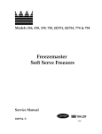
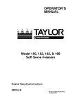
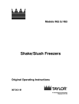
Model 161
Soft Serve Freezer
Service Manual
055155-S
10/18/07
Table of Contents
Section 1: Introduction . . . . . . . . . . . . . . . . . . . . . . . . . . . . . . . . . . . . . . . . . . . . . . .
1
Safety . . . . . . . . . . . . . . . . . . . . . . . . . . . . . . . . . . . . . . . . . . . . . . . . . . . . . . . . . . . . .
2
Refrigerant . . . . . . . . . . . . . . . . . . . . . . . . . . . . . . . . . . . . . . . . . . . . . . . . . . . . . . . . .
2
Model 161 Specifications . . . . . . . . . . . . . . . . . . . . . . . . . . . . . . . . . . . . . . . . . . . . .
3
Installation Instructions . . . . . . . . . . . . . . . . . . . . . . . . . . . . . . . . . . . . . . . . . . . . . . .
5
Running Specifications . . . . . . . . . . . . . . . . . . . . . . . . . . . . . . . . . . . . . . . . . . . . . . .
6
Section 2: Controls . . . . . . . . . . . . . . . . . . . . . . . . . . . . . . . . . . . . . . . . . . . . . . . . . . .
7
Generation II Control Logic Board . . . . . . . . . . . . . . . . . . . . . . . . . . . . . . . . . . . . .
8
Service Tips for Generation II Boards . . . . . . . . . . . . . . . . . . . . . . . . . . . . . . . . . .
13
Control Overview . . . . . . . . . . . . . . . . . . . . . . . . . . . . . . . . . . . . . . . . . . . . . . . . . . . .
16
Refrigeration Schematic . . . . . . . . . . . . . . . . . . . . . . . . . . . . . . . . . . . . . . . . . . . . . .
17
Valve Functions . . . . . . . . . . . . . . . . . . . . . . . . . . . . . . . . . . . . . . . . . . . . . . . . . . . . .
18
Section 3: Troubleshooting . . . . . . . . . . . . . . . . . . . . . . . . . . . . . . . . . . . . . . . . . . .
19
General Troubleshooting Guide . . . . . . . . . . . . . . . . . . . . . . . . . . . . . . . . . . . . . . .
20
Electrical Troubleshooting . . . . . . . . . . . . . . . . . . . . . . . . . . . . . . . . . . . . . . . . . . . .
23
Section 4: Parts . . . . . . . . . . . . . . . . . . . . . . . . . . . . . . . . . . . . . . . . . . . . . . . . . . . . . .
25
Warranty Explanation . . . . . . . . . . . . . . . . . . . . . . . . . . . . . . . . . . . . . . . . . . . . . . . .
26
Model 161 Exploded View . . . . . . . . . . . . . . . . . . . . . . . . . . . . . . . . . . . . . . . . . . . .
28
Model 161 Panel Identification . . . . . . . . . . . . . . . . . . . . . . . . . . . . . . . . . . . . . . . .
31
Beater Door Assembly . . . . . . . . . . . . . . . . . . . . . . . . . . . . . . . . . . . . . . . . . . . . . . .
32
Accessories . . . . . . . . . . . . . . . . . . . . . . . . . . . . . . . . . . . . . . . . . . . . . . . . . . . . . . . .
33
Model 161
Table of Contents
Table of Contents - Page 2
X58494-27 Control A.-161 Gen II . . . . . . . . . . . . . . . . . . . . . . . . . . . . . . . . . . . . .
34
X55480-27 Control A.-Channel . . . . . . . . . . . . . . . . . . . . . . . . . . . . . . . . . . . . . . .
35
X59447-27 Box A.-Cap & Relay . . . . . . . . . . . . . . . . . . . . . . . . . . . . . . . . . . . . . .
36
Parts List . . . . . . . . . . . . . . . . . . . . . . . . . . . . . . . . . . . . . . . . . . . . . . . . . . . . . . . . . . .
37
Wiring Diagrams . . . . . . . . . . . . . . . . . . . . . . . . . . . . . . . . . . . . . . . . . . . . . . . . . . . .
43
CAUTION: Information in this manual is intended to be used by Taylor Authorized
Service Technicians only.
Note: Continuing research results in steady improvements; therefore, information
in this manual is subject to change without notice.
E November, 2006 Taylor
All rights reserved.
055155-S
The word Taylor and the Crown design
are registered trademarks in the United States
of America and certain other countries.
Table of Contents
Taylor Company
a division of Carrier Commercial Refrigeration, Inc.
750 N. Blackhawk Blvd.
Rockton, IL 61072
Model 161
Section 1: Introduction
Model 161
S
Safety
S
Refrigerant
S
Specifications
S
Installation Instructions
S
Running Specifications
1
Introduction
Safety
Refrigerant
______________________________
______________________________
Taylor uses R404A refrigerant. This refrigerant is
generally considered non-toxic and non-flammable;
however, any gas under pressure is potentially
hazardous.
We at Taylor are committed to manufacturing safe
operating and serviceable equipment. The many
built-in safety features that are part of all Taylor
equipment are aimed at protecting operators and
trained service technicians alike.
NEVER fill any refrigerant cylinder
completely with liquid. Filling the cylinder to
approximately 80% will allow for normal expansion.
This manual is intended exclusively for Taylor
authorized service personnel.
DO NOT attempt any repairs unless the
main power supply to the machine has been
disconnected. Failure to follow this instruction may
result in electrocution.
Refrigerant liquid sprayed onto the skin may
cause serious damage to tissue. Keep eyes and skin
protected. If refrigerant burns should occur, flush
immediately with cold water. If burns are severe,
apply ice packs and contact a physician
immediately.
Stationary appliances which are not
equipped with a power cord and a plug or other
device to disconnect the appliance from the power
source must have an all-pole disconnecting device
with a contact gap of at least 3 mm installed in the
external installation. Failure to follow this instruction
may result in electrocution.
Taylor reminds technicians to be cautious of
government laws regarding refrigerant recovery,
recycling, and reclaiming systems. If you have any
questions regarding these laws, please contact the
factory Service Department.
WARNING: R404A refrigerant used in conjunction
with polyolester oils is extremely moisture
absorbent. When opening a refrigeration system, the
maximum time the system is open must not exceed
15 minutes. Cap all open tubing to prevent humid air
or water from being absorbed by the oil.
This machine must be placed on a level
surface. Failure to comply may result in personal
injury or equipment damage.
DO NOT install the unit in an area where a
water jet could be used to clean or rinse the freezer.
Failure to follow this instruction may result in serious
electrical shock.
If the crossed out wheeled bin symbol is
affixed to this product, it signifies that this product is
compliant with the EU Directive as well as other
similar legislation in effect after August 13, 2005.
Therefore, it must be collected separately after its
use is completed, and cannot be disposed as
unsorted municipal waste.
This machine is designed to operate indoors, under
normal ambient temperatures of 70_-75_F
(21_-24_C). The machine has successfully
performed in high ambient temperatures of 104_F
(40_C) at reduced capacities.
The user is responsible for returning the product to
the appropriate collection facility, as specified by
your local code.
NOISE LEVEL: Airborne noise emission does not
exceed 78 dB(A) when measured at a distance of
1.0 meter from the surface of the machine and at a
height of 1.6 meters from the floor.
Introduction
For additional information regarding applicable local
laws, please contact the municipal facility and/or
local distributor.
2
Model 161
Model 161 Specifications
Freezing Cylinder
Air Cooled
Two, 1.5 quart (1.4 liter) volume.
Clearance: 6” (152 mm) on left and right, and 0” in
the rear. Install the air deflector provided and place
the rear of the unit against the wall to prevent
recirculation of warm air. Minimum air clearances
must be met to assure adequate air flow for
optimum performance.
Mix Hopper
Two, 8 quart (7.6 liter) capacity.
Beater Motor
Two, 0.5 hp.
Dimensions
Refrigeration Unit
Width: 21-1/8” (537 mm)
Depth: 26-5/8” (677 mm)
Height: 28-1/8” (715 mm)
Counter Clearance: Designed to rest on a plastic
pad directly on the counter top or optional cart.
One, 8,000 BTU/hr compressor. R404A.
Separate Hopper Refrigeration (SHR), one 300
BTU/hr. R134a. (Actual BTU’s may vary based on
application.)
Electrical
Approximate Weights
Total
Amps
Supplied with
NEMA Cord
208-230/60/1 Air
10.0
6-15P
220-230/60/1 Water
10.0
6-15P
220-240/50/1 Air
15.0
---
220-240/50/1 Water
15.0
---
Electrical
Net:
305 lbs. (138.3 kgs.)
Crated: 355 lbs. (161.0 kgs.)
Volume: 17.9 cu. ft. (0.51 cu. m.)
Availability and specifications are subject to
change without notice.
This unit may be manufactured in other electrical
characteristics. Refer to the local Taylor Distributor
for availability. (For exact electrical information,
always refer to the data label of the unit.)
This unit is designed and constructed to meet
stringent safety and sanitation requirements for NSF
and UL.
071018
Model 161
3
Introduction
Model 161 Specifications (Continued)
REAR VIEW
(WATER COOLED
ONLY)
WATER
OUT
(3/8” NPT)
WATER IN
(3/8” NPT)
26-5/8
(677)
24-3/16
(614)
21-1/8
(537)
POWER
CORD
25-1/4
(642)
28-1/8
(715)
7-3/4
(197)
7/8
(22)
AIR IN-NEAR SIDE
AIR OUT-FAR SIDE
(AIR COOLED ONLY)
19.625
(499)
TOP OF
DRAW
HANDLE
50-7/8
(1292)
15-1/2
(394)
43-11/16
(1110)
TOP OF
DRAW
HANDLE
24-1/16
(611)
52-5/16
(1329)
31-13/16
(808)
18
(458)
20-7/8
(531)
17-5/8
(448)
60-9/16 (BOTH DOORS OPEN)
(1539)
3-5/8
(92)
NOTE:
FIGURES IN PARENTHESES INDICATE MILLIMETERS.
071018
Introduction
4
Model 161
Installation Instructions
Air Cooled Units
Beater Rotation
Air cooled units require a minimum of 6” (152 mm)
of clearance around all sides of the freezer . Failure
to allow for adequate clearance can reduce the
refrigeration capacity of the freezer and possibly
cause damage to the compressor.
Beater rotation must be clockwise as viewed looking
into the freezing cylinder.
Electrical Connections
Each freezer requires a dedicated power supply.
Check the data label on the freezer for fuse, circuit
ampacity and electrical specifications. Refer to the
wiring diagram, provided inside the control box, for
proper power connections.
In the United States, this equipment is intended to
be installed in accordance with the National
Electrical Code (NEC), ANSI/NFPA 70-1987. The
purpose of the NEC code is the practical
safeguarding of persons and property from hazards
arising from the use of electricity. This code contains
provisions considered necessary for safety.
Compliance therewith and proper maintenance will
result in an installation essentially free from hazard!
In all other areas of the world, equipment should be
installed in accordance with the existing local codes.
Please contact your local authorities.
Figure 1
To correct rotation on a three phase unit, exchange
leads at the main terminal block.
CAUTION: Make sure the power switch
is in the OFF position before correcting the
beater rotation. Failure to do so may result in
electrocution or component damage.
Stationary appliances which are not equipped with a
power cord and a plug or other device to disconnect
the appliance from the power source must have an
all-pole disconnecting device with a contact gap of at
least 3 mm installed in the external installation.
Electrical connections are made directly to the
terminal block provided in the control box.
CAUTION: This machine must be
properly grounded! Failure to do so can result
in severe personal injury from electrical shock!
FOLLOW YOUR LOCAL ELECTRICAL CODES!
Model 161
5
Introduction
Running Specifications
Pressures/Temperatures
High Side (Discharge)
The following are the Taylor recommended settings
for various components within these models. The
Model 161 uses R404A.
High side pressure varies for air cooled units,
depending on the ambient temperature.
Ambient Temperature
Expansion Valve - Low Side (Suction)
Normal Operating Head
Pressures
Soft Serve
Air Cooled - 21 psi. (145 kPa) for a normal product
of 16_ to 18_F (-8.8_to -7.7_ C). Set each side
separately at 16 psi (110 kPa).
Expansion Valve Adjustment
Place your gauge on the access valve on the suction
line (located at the compressor).
Adjust the pressure higher or lower by turning the
adjustment screw. Clockwise turns will raise the
pressure and counterclockwise turns will lower the
pressure.
F.
C.
PSI
70_
21.1_
240 - 270
(1,655 - 1,862 kPa)
80_
26.7_
270 - 300
(1,862 - 2,069 kPa)
90_
32.2_
300 - 340
(2,069 - 2,344 kPa)
100_
37.8_
340 - 380
(2,344 - 2,620 kPa)
Make expansion valve adjustments with mix in the
cylinder and the freezer in the AUTO mode. Be sure
to allow adequate time for the pressure to stabilize.
Repeat these instructions for the other side of the
unit. The expansion valve on each side of the unit
must be set separately.
Introduction
6
Model 161
Section 2: Controls
Model 161
S
Generation II Control Logic Board
S
Service Tips for Generation II Boards
S
Control Overview
7
Controls
Generation II Control Logic Board
The Generation II logic board’s primary function is to
interpret modes of operation. The board monitors
mix levels and temperatures by sending commands
to the control’s power board. Commands are sent
via a ribbon cable, enabling the proper relays on the
power board to open or close. (See Control
Overview illustration on page 16.)
As of July, 1996 we have modified the differential on
Generation II controls from 13°F/7.2°C to
4.5°F/2.5°C in order to meet the new NSF mix
temperature requirements. The new control has a
shunt (jumper) to select proper temperatures. This
shunt is located beneath the dip switches on the left
side of the control. The shunt is set in the upper
position for 4.5°F/2.5°C differential for use on mix
hopper systems and in the lower position for
13°F/7.2°C differential for use on mix cabinet
systems. The new control is compatible with older
units. This change will require new part numbers as
follows:
Function
Interpret a mode of operation/monitor mix level and
temperature/monitor product viscosity or product
temperature and send a command to the power
board through a ribbon cable enabling the proper
relays on the power board to be open or closed.
Old Part No.
X36641-SER Gen. II
X38523-SER Gen. II-W/Chime
New Part No.
X36641SER1
X38523SER1
Power Board (Part Number)
X32326-SER
Thermistor Probes
Logic Board (Part Numbers)
There are two types of thermistor probes used on
model 161 freezers. The resistance value of the
thermistor probes corresponds with the temperature.
As the temperature becomes warmer, the probe
resistance decreases.
X31602
X55540
- Barrel Probe (Senses temperature
of product in freezing cylinder.)
- Hopper Probe (Senses temperature
of mix in hopper.)
Approximate probe resistance readings:
10,000 OHMS at room temperature (77_F/25_C).
30,035 OHMS at hopper temperature (35_F/2_C).
48,636 OHMS at soft service temperature
(18_F/-7.7_C).
Controls
8
Model 161
Viscosity Function
In soft serve freezers the logic board monitors amp
draw on the beater motor, which is directly related to
the viscosity of the product in the freezing cylinder.
When the amp draw reaches its set point, the unit
cycles off. Therefore, the viscosity of the product will
always be consistent even through its temperature
may vary slightly.
To monitor amperage, L1 power supplied to the
beater motor must pass through the power board
beater terminals. The same softech controls are
used in both single and three phase applications.
For this reason the control must be set to operate in
an amperage range which relates to the beater
motor amperage and the desired product viscosity
setting.
The selected amperage range simply determines the
adjustment span of the viscosity adjustment
potentiometer on the logic board. The jumper on the
power board determines the amperage range
selection. The jumper is placed on the pin which
corresponds to the beater motor amperage when the
desired product viscosity is attained. See page 16
to locate the range selection jumper.
2.4 PIN - 1.2 AMP to 2.4 AMP
5.0 PIN - 2.5 AMP to 5.0 AMP
8.0 PIN - 4.0 AMP to 8.0 AMP
11.2 PIN - 5.7 AMP to 11.2 AMP
2.
Turn the viscosity adjustment screw to the
“MAX” position.
3.
With the freezer properly primed, actuate the
refrigeration cycle (press “AUTO”).
Model 161
5.
Cancel the refrigeration cycle (press “AUTO”).
6.
Using the chart, set what range the beater
motor amperage falls into and place the jumper
on the proper pin. (Note: See previous chart for
amperage range.)
7.
Press “AUTO”. When amperage achieves the
previously noted beater motor amperage, turn
the viscosity adjustment screw
counterclockwise slowly until the unit cycles
off.
8.
Draw several samples to verify that the
amperage at cycle off and product quality
remains consistent.
The mix setting is the temperature adjustment for
the mix hopper.
Ideal mix temperature = 38_F (3.3_C) to 40_F
(4.4_C).
Setting Viscosity Adjustment
Place an amp probe on one of the L1 leads on
the beater terminal on the power board.
During the freezing process, draw a sample
and inspect the product appearance. When the
desired product viscosity and appearance is
achieved, note the beater motor amperage.
Mix Adjustment
Viscosity Control Range Selections
1.
4.
Cut-out temperature will always be 4.5_F (2.5_C)
lower than the cut-in temperature. (See SB 2474.)
The range for cut-in temperature is “MIN”
approximately 52°F (11.0°C) and “MAX”
approximately 36°F (2.2°C).
9
Controls
Setting the Mix Hopper Temperature
Setting Standby Temperatures
1.
To set the mix hopper temperature, fill the
hopper at least half full with approximately 40_F
(4.4_C) mix.
1.
With the unit properly primed with fresh mix,
turn the STANDBY adjustment screw to the
warmest position.
2.
Install a suction pressure gauge at the EPR
valve (evaporator pressure regulator) and verify
the correct operating pressure. Adjust if
necessary.
2.
Press “STANDBY”.
3.
When the main refrigeration system cycles off,
draw a sample portion and check the product
temperature.
4.
To get the desired standby temperature, make
a slight clockwise adjustment and wait until the
main refrigeration cycles off.
3.
4.
Set the “MIX” potentiometer to mid-range.
Allow the mix hopper refrigeration system to
cycle until the mix temperature is stabilized.
Adjust the setting if necessary.
Note: The temperature adjustment must be made
on the left logic board.
Standby Adjustment
Maintains mix temperature in the freezing cylinder
during long “no sale” periods to prevent over-beating
of the product.
Ideal standby temperature = 30_F (1.1_C) to 35_F
(1.7_C).
Cut-out temperature will always be 4_F (2_C) lower
than the cut-in temperature.
The range for cut-in temperature is “MIN”
approximately 44°F (6.6°C) and “MAX”
approximately 30°F (-1.1°C).
Controls
10
Model 161
Thermistor Curve
When checking a thermistor probe, first determine
the present temperature at the probe and find it on
this chart along with the approximate correct
ohmmeter reading. The ohmmeter reading may vary
F._
-10
-9
-8
-7
-6
-5
-4
-3
-2
-1
0
1
2
3
4
5
6
7
8
9
10
11
12
13
14
15
16
17
18
19
20
21
22
Model 161
C._
-23.3
-22.7
-22.2
-21.6
-21.1
-20.5
-20.0
-19.4
-18.8
-18.3
-17.7
-17.2
-16.6
-16.1
-15.5
-15.0
-14.4
-13.8
-13.3
-12.7
-12.2
-11.6
-11.1
-10.5
-10.0
-9.4
-8.8
-8.3
-7.7
-7.2
-6.6
-6.1
-5.5
from the correct one. Determine whether the
difference is acceptable. If a probe is actually faulty,
the difference will be great.
K OHM
118.201
114.394
110.709
107.143
103.692
100.352
97.120
94.085
91.144
88.296
85.536
82.863
80.273
77.765
75.334
72.980
70.627
68.350
66.147
64.014
61.951
59.953
58.021
56.150
54.340
52.854
51.409
50.003
48.636
47.306
46.012
44.754
43.530
F._
23
24
25
26
27
28
29
30
31
32
33
34
35
36
37
38
39
40
41
42
43
44
45
46
47
48
49
50
51
52
53
54
55
11
C._
-5.0
-4.4
-3.8
-3.3
-2.7
-2.2
-1.6
-1.1
-0.5
0
0.5
1.1
1.6
2.2
2.7
3.3
3.8
4.4
5.0
5.5
6.1
6.6
7.2
7.7
8.3
8.8
9.4
10.0
10.5
11.1
11.6
12.2
12.7
K OHM
42.340
41.136
39.967
38.830
37.727
36.654
35.612
34.599
33.616
32.660
31.760
30.885
30.035
29.207
28.403
27.620
26.859
26.120
25.400
24.721
24.059
23.416
22.789
22.180
21.586
21.009
20.447
19.900
19.884
18.881
18.392
17.915
17.451
Controls
F._
56
57
58
59
60
61
62
63
64
65
66
67
68
69
70
71
72
73
74
75
76
77
78
79
80
81
82
83
84
85
86
87
88
89
90
91
92
93
94
C._
13.3
13.8
14.4
15.0
15.5
16.1
16.6
17.2
17.7
18.3
18.8
19.4
20.0
20.5
21.1
21.6
22.2
22.7
23.3
23.8
24.4
25.0
25.5
26.1
26.6
27.2
27.7
28.3
28.8
29.4
30.0
30.5
31.1
31.6
32.2
32.7
33.3
33.8
34.4
K OHM
16.998
16.557
16.128
15.710
15.315
14.929
14.554
14.187
13.830
13.482
13.143
12.812
12.490
12.185
11.888
11.598
11.315
11.039
10.769
10.507
10.250
10.000
9.763
9.532
9.306
9.085
8.870
8.659
8.454
8.254
8.058
7.872
7.691
7.513
7.340
7.171
7.006
6.884
6.686
F._
95
96
97
98
99
100
103
106
109
112
115
118
121
124
127
130
133
136
139
142
145
148
151
154
157
160
163
166
169
172
175
178
181
184
187
190
193
196
199
C._
35.0
35.5
36.1
36.6
37.2
37.7
39.4
41.1
42.8
44.4
46.1
47.8
49.4
51.1
52.8
54.4
56.1
57.8
59.4
61.1
62.8
64.4
66.1
67.8
69.4
71.1
72.8
74.4
76.1
77.8
79.4
81.1
82.8
84.4
86.1
87.8
89.4
91.1
92.8
K OHM
6.532
6.386
6.242
6.102
5.966
5.832
5.448
5.096
4.769
4.466
4.184
3.922
3.680
3.454
3.244
3.048
2.866
2.696
2.539
2.391
2.252
2.124
2.004
1.891
1.785
1.687
1.594
1.508
1.427
1.351
1.279
1.212
1.149
1.090
1.034
.982
.932
.886
.842
070809
Controls
12
Model 161
Service Tips for Generation II Boards
Initial Service Tips
1.
Check all connections.
2.
Check the cable to verify that it is secure.
3.
Verify that all pins are securely fastened in their
sockets.
4.
Verify that all cables correctly face away from
the boards. If the cable is attached incorrectly,
damage to the logic board will occur. Beater
motor operation will be disabled.
5.
Verify probe resistance.
6.
Use the self-test program.
Figure 2
Each light corresponds with a particular relay. The
light on the panel will not extinguish until the test is
completed for that particular relay.
Self-Test Program
Logic Board Light
MIX LOW
MIX OUT
MIX
STANDBY
WASH
AUTO
PUMP
The Generation II controls are programmed for a
self-test. The control can be used to help identify
problems in the power board, the logic board, and
the thermistor probes. The self-test program is not
intended to, and will not take the place of a
reasonable and prudent service technician.
The self-test program is divided into two sections.
The first section is performed automatically by the
logic board itself and the second section is
performed by the technician.
When the self-test is initiated, all eight lights will
remain on for three seconds. At this time, the
processor will begin to check the power board relays
as follows:
This test is designed to aid in identifying problems
within the logic board, the power board, or the
thermistor probes.
Note: Each relay closes for three seconds during
this test. As the relay opens, the corresponding light
extinguishes. There is a ten second pause between
the activation of each relay.
Self-Test - Part I
1.
The self-test program is initiated by holding down
the MIX, WASH, AND PUMP keys on the logic
board while simultaneously turning on the power
switch. Hold down the keys until all eight lights
illuminate.
The SET POINT light turns off.
Ten seconds after the SET POINT light turns
off:
Note: If all eight lights do not illuminate, or if the
test cannot be initiated, the logic board is defective.
Model 161
Corresponding Relay
Mix Relay
Fan Relay
Pump Relay
Beater Motor Relay
Compressor Relay
Spinner Relay
Portion Relay
13
2.
The MIX relay closes and opens again. The
MIX LOW light extinguishes.
3.
The FAN relay closes and opens again. The
MIX OUT light extinguishes.
Controls
4.
The PUMP relay closes and opens again. The
MIX light extinguishes.
5.
The “BTR” (beater motor) relay closes and
opens again. The STANDBY light extinguishes.
6.
The “COM” (compressor) relay closes and
opens again. The WASH light extinguishes.
7.
All lights are off and a tone sounds for three
seconds. This designates the end of the first
section.
These lights create a bar graph which is directly
related to the product temperature. “MIX” is warm
and “PUMP” is cold.
1.
The SET POINT light is illuminated, indicating
that the control is reading the soft serve
viscosity potentiometer.
2.
Rotate the adjustment screw back and forth
from “MIN” to “MAX”. The bar graph should
travel accordingly. This indicates that the
potentiometer is functional.
If all or most of the power board relays fail to close,
the logic board is defective. If only one relay fails to
close, the power board is defective. This test can be
used to determine if a problem exists with the logic
board, the power board, or elsewhere in the freezer.
In other words, if during the test the beater relay
closes on the power board, but the beater motor
contactor does not operate, the problem occurs after
the command reaches the power board.
If the bar graph lights do not react, the logic
board is defective.
IMPORTANT: If the freezer’s controls
have been set previously, return the adjustment
to its original position. For example, if the
WASH light was illuminated before an
adjustment screw was rotated - - before going
to the next step - - rotate the adjustment screw
until the WASH light is illuminated again.
Self-Test - Part II
When the first section of the self-test is complete,
the control will advance to the starting point of the
second section. The technician will have to complete
this portion of the test. The first part of this section
verifies the function of the control potentiometers
(adjustment screw).
During this test, the MIX, STANDBY, WASH, AUTO,
and PUMP lights function in direct relationship with
the “MIN” and “MAX” adjustments of the
potentiometer. In other words, when the adjustment
screw is turned all the way to “MIN”, the MIX light
will be illuminated. When the adjustment is turned all
the way to “MAX”, the light will travel down and
illuminate the PUMP light. If the screw adjustment is
made between the “MAX” and the “MIN” adjustment,
one of the other lights will illuminate depending on
the adjustment.
Controls
3.
Press the MIX key once.
4.
The MIX LOW light is illuminated, indicating
that the control is reading the MIX
potentiometer.
5.
Rotate the adjustment screw as in Step 2.
6.
Press the MIX key once.
7.
The MIX OUT light is on, indicating the control
is reading the STANDBY potentiometer.
8.
Rotate the adjustment screw as in Step 2.
9.
Press the MIX key once.
10.
14
The MIX LOW light is illuminated, indicating
that the control is reading the “MIX 1” terminal.
Model 161
11.
The capability of this terminal to read the
thermistor probe can be checked by the
following method:
a.
Remove the thermistor probe wire from the
“MIX 1” terminal.
b.
Connect the “MIX 1” terminal directly to
ground (simulating a warm probe). The
MIX light will illuminate.
c.
Remove the terminal connection from
ground (simulating a cold probe). The
PUMP light will illuminate.
If the lights do not react, the panel is defective.
Model 161
15
12.
Press the MIX key once.
13.
The MIX OUT light is illuminated, indicating that
the control is now reading the BARREL
(freezing cylinder) probe terminal.
14.
Check the BARREL (freezing cylinder) probe
(as in Step 13) by removing the wire from the
panel.
15.
Press the MIX key again, and the self-test
program is terminated.
Controls
Control Overview
RIBBON CABLE
032445
RIBBON CABLE
032445
BOARD-LOGIC
GEN 2.6
X36641SER1
MIX
OUT
DRAW
SHK
PUMP
MIX 1
BRL
PROBE
FAN
MIX
LOW
MIX 2
MIX
OUT
DRAW
SOFTECH CONTROL
MIX OUT
STANDBY
WASH
AUTO
4
5
6
7
8
8
MAX
MIN
STANDBY
MAX
MIN
4.5
COM
13
MIX
DIFF.
SHUNT
MIX OUT
STANDBY
WASH
AUTO
S.S. VISCOSITY
SHAKE TEMP.
MAX
MIN
FAN
MIX 2
MAX
MIX
MIN
PUMP
STANDBY
MAX
MIN
MAX
AMP
:- 5
GND
L2
BEATER
BEATER
CABLE
CABLE
2.4
5
8
11.2
2.4
5
8
11.2
O.L.
O.L.
COM
BTR
PUMP
FAN
COM
MIX
POWER BOARD
X32326-SER
Controls
BRL
PROBE
GND
7
MIN
MIX
MIX
MIX LOW
L1
6
S.S. VISCOSITY
SHAKE TEMP.
MIX 1
SET POINT
L2
5
AMP
:- 5
4
TAYLOR CO.
36641-1
AMETEK/DIXON
000-49560
DIP SWITCH
UP = OFF
1 - COMP 5
2 - COMP 10
3 - BTR 5
4 - BTR 10
5 - FAN 2
6 - STBY DIS
7 - INTERVAL
8 - INTERVAL
PUMP
3
3
MIX
DIFF.
SHUNT
SHK
PUMP
SOFTECH CONTROL
2
2
4.5
COM
13
MIX
MIX LOW
1
1
TAYLOR CO.
36641-1
AMETEK/DIXON
000-49560
DIP SWITCH
UP = OFF
1 - COMP 5
2 - COMP 10
3 - BTR 5
4 - BTR 10
5 - FAN 2
6 - STBY DIS
7 - INTERVAL
8 - INTERVAL
SET POINT
L1
MIX
LOW
BOARD-LOGIC
GEN 2.6
X36641SER1
BTR
PUMP
FAN
MIX
POWER BOARD
X32326-SER
16
Model 161
Refrigeration Schematic
HPR Thermistor Probe
Mix Tank
Freezing
Cylinder
Suction
Solenoid
Valve
Liquid
Solenoid
Valve
Dryer
Access Valve
AXV
20-22 PSI (134A)
Heat
Exchanger
Access Valve
EPR Valve
1-5 PSI
Condenser (1)
Capillary
Tube
Dryer
Compressor
Access
Valve
Access Valve
13-14
PSIRunning)
(R12)
(One
Side
29-31 PSI (Hp62)
(Hp62)
16-17
Pressure
Switch
Compressor
Model 161
Condenser
17
Controls
Valve Functions
COMP
LABEL
EPR
DESCRIPTION
Inlet Pressure Upstream
Regulator
Filter/Dryer
Controls
BASIC OPERATING
LOGIC
Limits the minimum
refrigerant pressure in the
hopper (currently set to 60
psig).
Limiting the minimum
refrigerant pressure in the
hopper prevents freezing of
product mix on the hopper
wall.
This keeps moisture, dirt,
metal, and chips from
entering the refrigerant
flow control valves.
This allows the liquid
refrigerant to be cooled
before it reaches the AXV
and TXV.
Heat
Exchanger
(sub cooler)
AXV
FUNCTION
Automatic expansion
valve of the freezing
cylinder circuit.
INPUT /
OUTPUT
When the liquid is
subcooled before it
reaches the refrigerant
control, the refrigeration
effect per unit mass of
refrigerant is increased.
Controls the refrigerant
flow during the cooling of
the freezing cylinder.
18
Model 161
Section 3: Troubleshooting
Model 161
S
General Troubleshooting Guide
S
Electrical Troubleshooting
19
Troubleshooting
General Troubleshooting Guide
PROBLEM
1. No product is being
dispensed.
2. The product is too thick.
3. The product is too soft.
Troubleshooting
PROBABLE CAUSE
REMEDY
Low on mix. The MIX OUT light is
on.
Add mix to the mix hopper
The power switch is in the OFF
position.
Place the power switch to the ON
position and press the AUTO key.
Beater motor is out on reset.
Allow the beater motor to cool.
Place the power switch to the
OFF position. Press the reset
button firmly. Place the power
switch to the ON position and
press the WASH key. Open the
side access panel and observe
that the drive shaft is turning
CLOCKWISE as viewed from the
front of the unit. Press the AUTO
key to return to the AUTO mode.
Incorrect usage of the mix feed
tube.
Follow the correct feed tube
procedures and use of air orifice.
Improper priming procedures.
Drain the freezing cylinder and
re-prime the unit.
The viscosity control is set too
cold.
Adjust the viscosity.
The draw rate is set too fast.
Adjust the draw rate to 5 - 7-1/2
oz. (142 g. - 213 g.) of product by
weight every 10 seconds.
Outdrawing the capacity of the
freezing cylinder.
The continuous draw rate is
approximately 15 cones.
There is inadequate air space
around the unit.
A minimum of 6” (15.2 cm) of
clearance around all sides is
required.
Dirty condenser or air filters on air
cooled units.
Clean regularly.
Inadequate water supply on water
cooled units.
Check the water supply. Check
the water lines for leaks or kinks.
Bad scraper blades.
Replace the scraper blades.
The viscosity control is set too
warm.
Adjust the viscosity.
Incorrect usage of the mix feed
tube.
Follow the correct feed tube
procedures and use of the air
orifice.
20
Model 161
PROBLEM
4. The mix in the hopper is too
warm.
PROBABLE CAUSE
REMEDY
The hopper cover is not in
position.
Clean the hopper cover and place
it in position.
The hopper temperature is out of
adjustment.
Adjust the temperature control.
5. The mix in the hopper is too
cold.
The hopper temperature is out of
adjustment.
Adjust the temperature control.
6. Product is collecting on top of
the freezer door.
The top o-ring on the draw valve
is improperly lubricated or worn.
Lubricate properly or replace the
o-ring.
7. Excessive mix leakage from
the bottom of the door spout.
The bottom o-ring on the draw
valve is improperly lubricated or
worn.
Lubricate properly or replace the
o-ring.
8. Excessive mix leakage into
the long drip pan.
The seal on the drive shaft is
improperly lubricated or worn.
Lubricate properly or replace the
seal.
The seal is installed inside-out on
the drive shaft.
Install the seal correctly.
Worn or missing o-rings.
Install or replace the o-rings.
Inadequate lubrication of the drive
shaft.
Lubricate properly.
The drive shaft and beater
assembly work forward.
Verify the refrigerant charge and
check for a shorted freezing
cylinder.
Worn rear shell bearing.
Replace the component.
Gear box out of alignment.
Re-align the gear box.
9. Excessive mix leakage from
the rear of the freezer into the
short drip pans.
10.The drive shaft is stuck in the
drive coupling.
11.Freezing cylinder walls are
scored
scored.
Model 161
Mix and lubricant have collected in Brush clean the rear shell bearing
the drive coupling.
area regularly.
Rounded corners of the drive
shaft, the drive coupling or both.
Replace worn component(s).
The gear box is out of alignment.
Re-align the gear box.
Missing or worn front bearing.
Install or replace the front bearing.
The beater assembly is bent.
The beater assembly must be
replaced.
The gear box is out of alignment.
Re-align the gear box.
21
Troubleshooting
PROBLEM
12.The unit will not run when in
the AUTO mode.
mode
PROBABLE CAUSE
REMEDY
The unit is unplugged.
Plug into wall receptacle.
The beater motor is out on reset.
Allow the beater motor to cool.
Place the power switch to the
OFF position. Press the reset
button firmly. Place the power
switch to the ON position, and
press the WASH key. Open the
side access panel and observe
that the drive shaft is turning
clockwise as viewed from the front
of the unit. Press the AUTO key to
return to the AUTO mode.
Note: Do not use metal objects to
press the reset button.
The circuit breaker is off, or the
fuse is blown.
Turn the breaker on, or replace
the fuse.
Low on mix. The MIX OUT light is
on.
Add mix to the mix hopper and
press the AUTO key.
The water is turned off, on water
cooled units.
Turn the water on.
The mix inlet hole is frozen up.
The hopper temperature needs
adjustment.
Incorrect usage of the mix feed
tube.
Follow the correct feed tube
procedures and use of the air
orifice.
14.Product is “popping” when
drawn.
The draw rate is set too fast.
The draw rate should be set at 5 7-1/2 oz. of product per 10
seconds.
15.The MIX LOW and MIX OUT
probes are not functioning.
There is milkstone build-up in the
hopper.
Clean the hoppers thoroughly.
13.Product is not feeding into the
freezing cylinder.
Troubleshooting
22
Model 161
Electrical Troubleshooting
The following information provides a sequential list
of electrical components that L-1 power travels
through to initiate various operations.
Wash Mode of Operation:
L-1 power travels through the power switch, beater
overload switch, the compressor high pressure
cut-out switch, the overload terminal (OL) on the
power board, the BTR terminal of the power board,
and energizes the coil of the beater motor contactor.
Auto Mode of Operation:
L-1 power travels through the power switch, beater
overload switch, the compressor high pressure
cut-out switch, the overload terminal (OL) on the
power board, the BTR terminal of the power board,
and energizes the coil of the beater motor contactor.
L-1 power travels through the power switch, beater
overload switch, the compressor high pressure
cut-out switch, the overload terminal (OL) on the
power board, the COM terminal of the power board,
and energizes the coil of the compressor contactor.
L-1 power travels through the power switch, beater
overload switch, the compressor high pressure
cut-out switch, the L-1 terminal of the power board,
the MIX terminal of the power board, and energizes
the hopper refrigeration compressor and condenser
fan.
Model 161
23
Troubleshooting
Notes:
Troubleshooting
24
Model 161
Section 4: Parts
Model 161
S
Warranty Explanation
S
Exploded Views
S
Complete Parts List
S
Wiring Diagrams
25
Parts
Warranty Explanation
Class 103 Parts:
The warranty for new equipment parts is one year from the original date of unit
installation, with a replacement parts warranty of three months.
Class 212 Parts:
The warranty for new equipment parts is two years from the original date of unit
installation, with a replacement parts warranty of twelve months.
Class 512 Parts:
The warranty for new equipment parts is five years from the original date of unit
installation, with a replacement parts warranty of twelve months.
Class 000 Parts:
Wear Items - no warranty.
CAUTION: Warranty is valid only if required service work is provided by an Authorized Taylor Service
Technician.
NOTE: Taylor reserves the right to deny warranty claims on equipment or parts if a non-approved refrigerant
was installed in the machine, system modifications were performed beyond factory recommendations, or
it is determined that the failure was caused by neglect or abuse.
Compressor Warranty Disclaimer
The refrigeration compressor(s) on this machine are
warranted for the term indicated on the warranty
card accompanying this machine. However, due to
the Montreal Protocol and the U.S. Clean Air Act
Amendments of 1990, many new refrigerants are
being tested and developed; thus seeking their way
into the service industry. Some of these new
refrigerants are being advertised as drop-in
replacements for numerous applications. It should
be noted that, in the event of ordinary service to this
machine’s refrigeration system, only the refrigerant
specified on the affixed data label should be used.
The unauthorized use of alternate refrigerants will
void your compressor warranty. It will be the owners’
responsibility to make this fact known to any
technicians they employ.
Parts
It should be noted, that Taylor does not warrant the
refrigerant used in its equipment. For example, if the
refrigerant is lost during the course of ordinary
service to this machine, Taylor has no obligation to
either supply or provide its replacement either at
billable or unbillable terms.
Taylor will continue to monitor the industry and test
new alternates as they are being developed. Should
a new alternate prove, through our testing, that it
would be accepted as a drop-in replacement, then
the above disclaimer would become null and void.
To find out the current status of an alternate
refrigerant as it relates to your compressor, call the
local Taylor Distributor or the Taylor Factory. Be
prepared to provide the model/serial number of the
unit in question.
26
Model 161
Notes:
Model 161
27
Parts
Model 161 Exploded View
7a
2
7
5
4
8
6
3
64
63
12b
58
20
57a
59
12a
54
55
56
53
26
51
24
37a
45
38
43
41
40
24
22
24
25
23
28
29
30
31
32
36
37
44
21f
27
37c
42
21e
21g
52
37b
26
21b
21c
21d
20a
21a
50
46
17
16
60
47
19
57
54a
49
13
15
12
61
48
14
6b
61a
63
62
6a
11
10
9
1
18
39
34 35
24
33
34
Figure 3
Parts
28
Model 161
Model 161 Exploded View
ITEM
DESCRIPTION
PART NO.
ITEM
DESCRIPTION
PART NO.
24
SCREW-10X3/8 SLOTTED HEX
015582
25
COVER-CAP.& RELAY BOX
055136
26
SCREW-10-32X1/2 SERR.
020982
27
BRACKET A.-COND-DANFOSS
X63562
28
NUT-10-32 WHIZ FLANGE LCK
020983
29
MOTOR-FAN 50 WATT W/GRD
029770-27
30
FAN-3 BLADE 12 ” PULL 24°
063397
31
SHROUD-CONDENSER
064356
32
LINE A.-LIQ *HTE-COND*AC
X64359
33
CONDENSER-AC 12LX16H X
2.5T 3 ROWS
048935
1
MOTOR-1/2 HP REMOTE
CAPS
055097-27G
2
NUT-5/16-18 WHIZ FLANGE
017327
3
SCREW-5/16-18X5/8 SERR.
017326
4
PULLEY-AK20X5/8
041162
5
VALVE-EXP-AUTO-1/4S X1/4
046365
6
LINE A.-LIQUID *SOLENOID
X55592-27
6a
VALVE-SOLENOID 7/64 ORF
043449-27
6b
TEE-1/4S-COPPER
003949
7
LINE A.-LIQ *HTE-DRY*AC*
X64360
7a
DRYER-FILTER 1/4 X 1/4 SLDR
048878
8
EXCHANGER A.-HEAT
X64357
34
SCREW-10-32X3/8 UNSL HWH
039381
9
SPACER-PROBE *SQ HOLE*
030966
35
BRACKET-FAN MOUNT
058675
10
DISC-PROBE *SQ HOLE*
030965
36
VALVE-ACCESS-1/4 MFLX1/4
047016
11
PROBE A.-MIX *SQUARE*
X30922
37
LINE A.-SUCTION *DANFOSS
X63559
12
SHELL A.-INSULATED
X58457
37a
VALVE-EPR 1/4S
022665
12a
BEARING-REAR SHELL
023648
37b
VALVE-ACCESS 1/4FL X 1/4
044404
12b
NUT-REAR BEARING
023647
37c
TEE-1/4S-COPPER
022665
13
GEAR A.*REDUCER 4 TO 1
025770-SER
38
COMPRESSOR PL35G
055187-27
14
WASHER-5/16 SAE FLAT CR3
017660
39
KIT-MOUNTING-COMPRESSR
047704
15
SCREW-1/4-20X3 HEX HEAD
025984
40
CONTROL A. -COMPLETE
X58494-27
16
SCREW-1/4-20X3-1/4 HEX HD
025985
41
COVER-CONTROL BOX
058496
17
PULLEY-5.7” PITCH DIA X 5/8
041498
42
BRACKET-BOX-CONTROL MT
055117
18
BELT-AX24
055201
43
PANEL A.-FRONT
X58488
19
BELT-AX45
045311
44
BOLT-CARRIAGE 1/4-20X3/4
012347
20
LINE A.-SUCTION
X64358-27
45
SCREW-6-32X3/8 SLTD BNDR
002201
20a
VALVE-SOL-1/4 ORF X 3/8 IN1/2 OUT
062019-27
46
PLATE-DEC
055512
47
BOARD-LOGIC-GEN 2.6-SD
X36641SER1
21
CONDENSER A.-DANFOSS
INCLUDES:
X63551-27G
48
SCREW-8X1/4 SLTD HEX
009894
21a
CONNECTOR-BX 3/8 STR
014569
49
CONTROL A.-CHANNEL
X55480-27
21b
SHROUD DANFOSS
048818
50
SWITCH A.-POWER
X52306
51
SCREW-10-24X1/2 TORX
002077
52
PLATE-MOUNTING
055507
53
BOX A.-CAP&RELAY
X59557-27
54
LINE A.-DISCHARGE
X63556
54a
SWITCH-PRESSURE 405 PSI
052663
55
COMPRESSOR L63B562BBCB
048727-27E
56
SCREW-5/16-18X1-1/2 HEX HD
001894
57
LINE A.-ACCESS DISCHARGE
X63554
21c
MOTOR-FAN
062253-27
21d
SCREW-10-32X3/8 UNSL HWH
039381
21e
SCREW-8X1/4 SLTD HEX
009894
21f
CONDENSER-A/C 7X6X1.25
027155
21g
DRYER-CAP TUBE .021 IDX9F
055522
21h
HARNESS-WIRE DANFOSS
063839
22
LINE-PROCESS AUX DRYER
055185
23
LINE-DISCHARGE *DANFOSS
063560
*NOT SHOWN
Model 161
29
Parts
Model 161 Exploded View (Continued)
ITEM
DESCRIPTION
PART NO.
ITEM
DESCRIPTION
PART NO.
57a
VALVE-ACCESS-1/4MFL X 3/8
053565
61
LINE A.-ACCESS LOW
X64407
58
STUD-NOSE CONE5/16-18X5/16
013496
61a
VALVE-ACCESS-1/4MFL X 3/8
053565
62
BRACKET-VALVE-ACCESS
053577
59
WASHER-5/16 USS FLAT CR3
000651
63
SCREW-1/4-20X1/2 SLT
051284
60
NUT-5/16-18 WHIZ FLANGE
017327
64
BRACKET-VALVE-ACCESS
055202
*NOT SHOWN
Parts
30
Model 161
Model 161 Panel Identification
4a
2
4
5
3
1
6
M
A
N
U
F
A
C
T
U
R
E
8
D
B
7
Y
R
T
H
E
T
R
A
O
C
Y
K
T O
L
N
O
,
R
I L
L I
N
C
O
O
M
I S
U
13
P
. S
. A
A
.
N
Y
12
11
9
10
Figure 4
ITEM
DESCRIPTION
PART NO.
ITEM
DESCRIPTION
PART NO.
1
PAN-DRIP *161*
055206
8
PANEL-SIDE-RIGHT *161*
X58490
2
PANEL A.-SIDE LEFT *161*
058491
9
GASKET-BASE PAN
055815
3
GASKET-HOPPER COVER
037042
10
TRAY-DRIP 16-7/8L X 5-1/8
020157-SP
4
COVER A.-HOPPER
X37963-SER
11
SHIELD-SPLASH
022765
4a
KNOB-MIX COVER
025429
12
PANEL-LOWER FRONT *161*
058493
5
TUBE-FEED
030797
13
PANEL A.-FRONT *161*
X58488
6
COLLAR-MIX PROBE
031628
7
PANEL-REAR *161*
058492
Model 161
31
Parts
Beater Door Assembly
16
15
12
1
14
13
2
7
3
11
5
4
6
8
10
9
Figure 5
ITEM
DESCRIPTION
PART NO.
ITEM
DESCRIPTION
PART NO.
1
DRAW VALVE
024763
9
DESIGN CAP
014218
2
O-RING 7/8 OD X .103 W
014402
10
PIVOT PIN A.-LONG
X38538
3
SEAL-VALVE
030930
11
GUIDE BEARING
014496
4
DOOR A.-3 SP 1.5 QT VALOX
X56906SER1
12
CENTER DRAW VALVE
031164
5
PIVOT PIN A.-SHORT
X38539
13
O-RING 2-3/4 OD X .139 W
019998
6
O-RING 5/16 OD X .070 W
016272
14
FRONT BEARING
023262
7
DRAW VALVE HANDLE
030564
15
BEATER ASSEMBLY
X24689
8
NUT-STUD
056802
16
O-RING-13/16 OD X .139 W
021278
Parts
32
Model 161
Accessories
Figure 6
ITEM
DESCRIPTION
PART NO.
1
PAIL-6·QT.
023348
2
BRUSH-REAR BRG 1” D X 2” LG
013071
3
BRUSH-DOUBLE·ENDED
013072
4
BRUSH-DRAW·VALVE·1” OD X
2” X 17”
013073
ITEM
DESCRIPTION
PART NO.
5
BRUSH-MIX·PUMP·BODY-3”X7”
WHITE
023316
6
LUBRICANT-TAYLOR·4·OZ.
047518
7
KIT·A.-TUNE·UP
X31167
*
SANITIZER KAY-5 125 PKTS
041082
*NOT SHOWN
Model 161
33
Parts
X58494-27 Control A.-161 Gen II
1 2
3
4 5
1 2
6
15
5
10 9
14
13 12 11 10 9
5
15
8
7
Figure 7
ITEM
DESCRIPTION
PART NO.
ITEM
10
OVERLOAD-THERMAL-2P2.4/3.6A
055249-27G
11
LUG-GROUNDING 260 W/GR.
SCREW
020928
12
SCREW-10-32X1/2 SERRATED
020982
13
NUT-10-32 WHIZ FLANGE
LOCKNUT
020983
14
LABEL-GROUNDING SYMBOL
017669
15
CABLE-RIBBON-PWR/RELAY-6
032445
*
HARNESS-WIRE-CONTROL
055838-27
*
HARNESS-WIRE-MAIN
063573-27
1
BOARD-POWER-GEN 1 & 2
X32326-SER
2
SCREW-6-32X5/8 UNSLTD
041363
3
CONTACTOR 230VAC 1PH
50/60HZ
055248-27
4
BLOCK-TERMINAL 7P 20A
300V
022606
5
SCREW-8X1/4 SLTD HEX
009894
6
BUSHING-SNAP 1 ID X 1-1/4OD 600288
7
BUSHING-SPLIT 43/64ID X 7/8
027691
8
BUSHING-SNAP 11/16 ID X 7/8
010548
9
BUTTON-RESET-RED PLASTIC 055249
Parts
DESCRIPTION
PART NO.
*NOT SHOWN
34
Model 161
X55480-27 Control A.-Channel
3
1a
5
4
1a
2
1e
1g
1d
1b
1b
1c
1f
Figure 8
ITEM
DESCRIPTION
PART NO.
1
SWITCH A.-DRAW
(INCLUDES: 1a-1f)
X55234
1a
BEARING-SWITCH
029244
1b
NUT-PUSH ON-1/2DIA. SHAFT
1c
ITEM
DESCRIPTION
PART NO.
1f
SCREW-4-40X1 SLTD ROUND
028890
1g
BRACKET-SWITCH
035524
2
SPRING-COMP.720X.063X2.00
023664
039735
3
ACTUATOR-SWITCH-PLASTIC
035609
SCREW-4-40 X 1 SLTD ROUND
028890
1d
4
E-RING-1/4 IN-ZD
034962
SWITCH-LEVER-SPDT-15A-125
027214
1e
5
ARM A.-SWITCH
X30736
INSULATOR-SWITCH 1/64
029099
Model 161
35
Parts
X59447-27 Box A.-Cap & Relay
1
9
8 4
1
9
2
8 4
7
3 4
6 4
5
Figure 9
ITEM
DESCRIPTION
PART NO.
1
CAPACITOR-START
72-88UF/330V
059757
2
CAPACITOR-START
161-193UF/25
031790
3
RELAY-START-COMPRESSOR
047067
4
SCREW-10X3/8 SLOTTED HEX
015582
5
BUSHING-SNAP 11/16 ID X 7/8
010548
Parts
ITEM
DESCRIPTION
PART NO.
6
STRAP-CAPACITOR 7-11/32
037890
7
CAPACITOR-RUN 30UF/370V
038487
8
STRAP-CAPACITOR 5-5/8 IN.
030258
9
CAPACITOR-RUN 10UF/370V
059998
*
HARNESS-WIRE-CAP/RELAY
063975-27
*NOT SHOWN
36
Model 161
BEARING-FRONT
BEARING-GUIDE
BEARING-REAR SHELL *150-52-68*
+COLLAR-REAR BEARING *150-2-68*
+NUT-REAR BEARING *150-52-68*
+TAB-BEARING LOCK *150-2-68*
BEATER A. *150-2-162-168*
+O-RING-13/16 OD X .139W
BELT-AX24
BELT-AX45
BELT-AX42
BLOCK-TERMINAL 7 POLE
BOARD-LOGIC-GEN 2.6-SD
BOARD-POWER-GEN 1 & 2
BOOT-VALVE-EXPANSION
BOOT-VALVE-EXPANSION
BRUSH-DOUBLE ENDED-PUMP&FEED T
BRUSH-DRAW VALVE 1”ODX2”X17”L
BRUSH-MIX PUMP BODY-3”X7”WHITE
BRUSH-REAR BRG 1IN.DX2IN.LGX14
CABLE-RIBBON-PWR/RELAY-60 IN
CAP-DESIGN-1.010”ID-6 POINT
COLLAR-HOLDING
COMPRESSOR L63B562BBCB
+CAPACITOR-RUN 30UF/370V
+CAPACITOR-START 161-193UF/25
+RELAY-START-COMPRESSOR
+HARNESS-WIRE-CAP/RELAY *161
COMPRESSOR RS80C1E-CAV-224
+CAPACITOR-RUN- 20UF/440V
+CAPACITOR-START-189-227UF/330V
+RELAY-START-COMPRESSOR
DESCRIPTION
023262
014496
023648
025564
023647
025027
X24689
021278
055201
045311
023877
022606
X36641SER1
X32326-SER
050900
027137
013072
013073
023316
013071
032445
014218
019481
048727-27E
038487
031790
047067
063975-27
051958-27
012906
033044-1
051957-27
PART
NUMBER
2
2
2
2
2
2
2
2
1
1
1
1
2
2
2
2
1
1
1
1
2
3
2
1
1
1
1
1
1
1
1
1
QTY.
000
000
000
103
000
000
103
000
000
000
000
103
212
212
000
000
000
000
000
000
103
000
103
512
103
103
103
103
512
103
103
103
WARR.
CLASS
Model 161
37
K5103487 & UP
K5103487 & UP
K5103487 & UP
K5103487 & UP
K5103487 & UP
K5103486 & PRIOR
K5103486 & PRIOR
K5103486 & PRIOR
K5103486 & PRIOR
K5103487 & UP
K5103486 & PRIOR
- 208-230V 60HZ 1PH
- 208-230V 60HZ 1PH
- 208-230V 60HZ 1PH
- 208-230V 60HZ 1PH
K5103487 & UP
K5103486 & PRIOR
208-230V 60HZ 1PH
REMARKS
PARTS
UPDATE
Parts List
+ Available Separately
Parts List
+ Available Separately
Parts List
38
Model 161
+HARNESS-WIRE-CAP/RELAY *161
COMPRESSOR PL35G
+CAPACITOR-START- 43-52UF/250V
+RELAY-START-COMPRESSOR
CONDENSER-AC 12LX16HX2.5T3RO
CONDENSER-AC-12LX16HX2.5-3 ROW
CONDENSER-AC 7X6X1.25-2 ROW
+DRYER-CAP. TUBE .021 ID X 9F
+HARNESS-WIRE-DANFOSS *161*
+SHROUD DANFOSS *060*710*
CONTACTOR-230VAC 1PH 50/60HZ
+BUTTON-RESET-RED PLASTIC
+OVERLOAD-THERMAL 2P-2.4/3
COVER A.-HOPPER *162-168*
KNOB-MIX COVER
+GASKET-HOPPER COVER-8QT
CORD-POWER-250V-15A-95”L-SO
CORE-SCHRADER VALVE-TEFLON
DECAL-DEC-TAYLOR 161 GEN 11
DECAL-INST-CLN HPR
DECAL-TROUBLESHOOT
DIAGRAM-WIRING *161*
DIAGRAM-WIRING *161*
DOOR A.-3SPT 1.5QT VALOX W/BAF
O-RING-2-3/4 OD X .139W
HANDLE-DRAW VALVE
PIN A.-PIVOT *168-LONG*
O-RING-5/16 OD X .070W
PIN A.-PIVOT *168-SHORT*
O-RING-5/16 OD X .070W
VALVE-DRAW *150-2*
O-RING-7/8 OD X .103W
VALVE-DRAW-CENTER *TM*
DESCRIPTION
055840-27
055187-27
033041
055358
048935
055140
027155
055522
063563
048818
055248-27
055249
055249-27G
X37963
025429
037042
042936-27
037047
055511
019029
038374
063820-27S
055376-27S
X56906SER1
019998
030564
X38538
016272
X38539
016272
024763
014402
031164
PART
NUMBER
1
1
1
1
1
1
1
1
1
1
3
2
2
1
1
1
1
2
1
1
1
1
1
1
2
3
1
1
1
1
2
4
1
QTY.
103
512
103
103
103
103
103
103
103
103
103
103
103
103
103
000
103
103
000
000
000
000
000
103
000
103
103
000
103
000
103
000
103
WARR.
CLASS
DRAW VALVES
PIVOT PINS
PIVOT PINS
K5103487 & UP - 208-230V 60HZ 1 PH
K5103486 & PRIOR - 208-230V 60HZ 1PH
K3013048 & UP
DOOR
J5103487 & UP - MAIN
J5103486 & PRIOR - MAIN
SHR K5103487 & UP
SHR
SHR
SHR
BEATER MOTOR RELAY
K5103486 & PRIOR - 208-230V 60HZ 1PH
SHR
REMARKS
PARTS
UPDATE
+ Available Separately
Model 161
39
Parts List
SEAL-VALVE
DOOR A.-3 SPOUT-1.5 QT
DRYER-CAP. TUBE .021 ID X 9FT
DRYER-FILTER 1/4 X 1/4 SOLDER
DVD-OPS TRAIN VIDEO*TAYLORMATE
FAN-3 BLADE 12 ” PULL 24DEG CW
FASTENER-CLIP 1/4-20 U-TYPE
FASTENER-CLIP 10-32 J TYPE
FILTER-AIR 13.5X17.75X7/16
GASKET-BASE PAN *161*
GEAR A.*REDUCER 4 TO 1
HOOD A. *161* SOLDERED
KIT A.-TUNE UP*162-168*
BEARING-FRONT
BEARING-GUIDE
CAP-DESIGN-1.010”ID-6 POINT
O-RING-13/16 OD X .139W
O-RING-2-3/4 OD X .139W
O-RING-5/16 OD X .070W
O-RING-7/8 OD X .103W
SEAL-VALVE
TOOL-O-RING REMOVAL-FREEZER
LABEL-CAUTION-GRD-PERM-ENG/SP
LABEL-DOOR-MOVE PART
LABEL-SW-POWER-OFF/ON-SYMBOLS
LABEL-WARN-COVER
LABEL-WARN-ELEC-TW-SMALL
LEG-4” 3/8-16 STUD
+CAP-RUBBER
LUBRICANT-TAYLOR 4 OZ.
MAN-OPER 161
MOTOR-1/2 HP REMOTE CAPS
+CAPACITOR-RUN 10UF/370V
DESCRIPTION
030930
X30753-SER
055522
048878
037665-DVD
063397
045865
048353
042703
055815
025770
X55118
X31167
023262
014496
014218
021278
019998
016272
014402
030930
048260-WHT
032164
032749
052632
051433
032718
036397
037268
047518
055155-M
055097-27G
059998
PART
NUMBER
1
1
1
1
1
1
8
2
1
1
2
1
1
2
2
3
2
2
2
4
1
1
1
1
1
5
1
4
4
1
1
2
2
QTY.
000
103
000
000
000
103
000
000
000
000
212
103
000
000
000
000
000
000
000
000
000
000
000
000
000
000
000
103
000
000
000
212
103
WARR.
CLASS
K5103881 & UP - 208-230V 60HZ 1 PH
K5103487 & UP
S/N K6035648 & PRIOR
S/N K6036537 & UP
K5103487 & UP
PANELS
RIGHT PANEL
CENTER DRAW VALVE
K2024231 & PRIOR USE X56906-SER KIT
SHR
REMARKS
PARTS
UPDATE
+ Available Separately
Parts List
40
Model 161
+CAPACITOR-START 72-88UF/330V
MOTOR-1/2 HP 1PH 60 HZ
+CAPACITOR-START 43-52UF/250V
+CAPACITOR-RUN- 9-11UF/370V
MOTOR-FAN
MOTOR-FAN 50 WATT
+FAN-3 BLADE 12 ” PULL 24DEG
+FAN-5 BLADE 12” PUSH 22DEG CCW
NUT-STUD *161-162-168*
NUT-STUD *150-152-162-168*
OVERLOAD-THERMAL-2P-2.4/3.6A
PAIL-6 QT.
PAN-DRIP *161*
PANEL A.-FRONT *161*
PANEL-SIDE-LEFT *161*
PANEL-LOWER-FRONT *161*
PANEL-REAR *161*AC
PANEL A.-SIDE RIGHT *161*
PANEL A.-FRONT *161*
PANEL A.-SIDE LEFT *161*
PANEL-LOWER FRONT *161* GENII
PANEL-REAR *161*
PANEL-SIDE-RIGHT *161*
PANEL-SKIRT-AIR *161*
PLATE-DEC *161* GENII
PROBE A.-MIX *SQUARE*
+DISC-PROBE *SQ HOLE*
+SPACER-PROBE *SQ HOLE*
PROBE A.-THERMISTOR
PROBE-THERMISTOR-BARREL-2% TOL
PULLEY-5.7” PITCH DIA X 5/8
PULLEY-AK20X5/8
RESISTOR A.-*161* CONT. BOX*
DESCRIPTION
059757
055097-27
056168
025962
062253-27
029770-27
063397
049009
056802
034829
055249-27G
023348
055206
X58488
058491
058493
058492
X58490
X55203
X55122
055513
055129
055130
055508
055512
X30922
030965
030966
X31602
038061-BLK
041498
041162
X55449
PART
NUMBER
2
2
2
2
1
1
1
1
2
2
2
1
2
1
1
1
1
1
1
1
1
1
1
1
1
2
2
2
2
1
2
2
1
QTY.
103
212
103
103
103
103
103
103
103
103
103
000
103
103
103
103
103
103
103
103
103
103
103
103
103
103
103
103
103
103
103
103
103
WARR.
CLASS
SHR
BARREL
GEAR
BEATER MOTOR
BEATER MOTOR CONTACTOR
K5103486 & PRIOR
K5103487 & UP
K5103487 & UP
K5103487 & UP
K5103487 & UP
K5103487 & UP
K5103486 & PRIOR
K5103486 & PRIOR
K5103486 & PRIOR
K5103486 & PRIOR
K5103486 & PRIOR
K5103486 & PRIOR
K5103487 & UP
K5103486 & PRIOR
K3013048 & UP - HANDSCREWS
K2024231 & PRIOR - HANDSCREWS
BEATER MOTOR OVERLOAD
K5103487 & UP
K4126923 & PRIOR - 208-230V 60HZ 1PH
K4126923 & PRIOR
K4126923 & PRIOR
K5103881 & UP - 208-230V 60HZ 1 PH
REMARKS
PARTS
UPDATE
+ Available Separately
Model 161
41
Parts List
SANITIZER KAY-5 125 PACKETS
SHELL A.-INSULATED *161*
+STUD-NOSE CONE-5/16-18X5/16-18
SHELL A.-INSULATED *161*GEN 11
+STUD-NOSE CONE-5/16-18X5/16-18
SHIELD-SPLASH *5454-8-752-336*
SHROUD-CONDENSER *161*
SHROUD-CONDENSER *161*
SHROUD DANFOSS *060*710*
SWITCH A.-DRAW *161*
+ACTUATOR-SWITCH, PLASTIC
+ARM A.-SWITCH *162-168*
BEARING-SWITCH
BRACKET-SWITCH *168*
+E-RING-1/4 IN-ZD
INSULATOR-SWITCH 1/64 ARMITE
NUT-PUSH ON-1/2DIA. SHAFT
SCREW-4-40X1 RD HD STEEL-ZP
+SCREW-6-32X3/8 BIN.HD SLOT SS
+SPRING-COMP.720X.063X2.00
SWITCH-LEVER-SPDT-15A-125-250V
SWITCH-PRESSURE 405 PSI-SOLDER
SWITCH-TOGGLE-4PDT*ON-NONE-ON
TRAY-DRIP 16-7/8L X 5-1/8
TUBE-FEED-SS-TM-TWIN
VALVE-ACCESS 1/4FL X 1/4SOLDER
VALVE-ACCESS-1/4 MFLX1/4 S-90
VALVE-ACCESS-1/4MFL X 3/8ODSDR
VALVE-EPR 1/4S
VALVE-EXP-AUTO-1/4S X1/4 FPT
VALVE-EXP-AUTO-1/4S X 1/4FPT
+BOOT-EXPANSION VALVE
VALVE-SOLENOID 5/16ORFX1/2ODF
DESCRIPTION
041082
X58457
013496
X55629
013496
022765
064356
055128
048818
X55234
035609
X30736
029244
035524
034962
029099
039735
028890
002201
023664
027214
052663
037394
020157
030797
044404
047016
053565
022665
046365
047232
027137
044982-27
PART
NUMBER
2
1
2
1
1
1
1
2
2
2
4
2
2
2
4
4
4
2
2
1
1
1
2
1
1
2
1
2
2
2
2
1
QTY.
000
512
103
512
103
103
103
103
103
103
103
103
000
103
000
000
000
000
000
103
103
103
103
103
103
103
103
103
103
103
103
000
103
WARR.
CLASS
SUCTION LINE
SHR
K5103487 & UP
K5103486 & PRIOR
SHR
K5103487 & UP
K5103486 & PRIOR
SHR
K1075174-K5103486
K5103487 & UP
REMARKS
PARTS
UPDATE
+ Available Separately
Parts List
42
Model 161
WATER COOLED 220-240V 50HZ 1 PH
ADAPTOR-3/8MP X 1/2 BARB-BR
BRACKET-VALVE-W/C *C708*
CLAMP-HOSE-ADJ 7/16 X 25/32
CONDENSER-WC-SPIRAL 11-1/2 O
HOSE-RUBBER 1/2 ID X 7/8 OD
PANEL-REAR *161*WC*
PANEL-SIDE *161*R*WC*
VALVE-WATER 3/8 REG/HEAD PRESS
011021
058440
010031
049309
R50200
063837
063838
046686
024156
063820-40S
055376-40S
037665-DVD
048727-40E
027087
031790
048766
051958-40
023606
051960
051957-40
051656-95
055097-40G
059759
055097-34
026657
037665-PAL
BLOCK-TERMINAL-7 POLE GREEN
DIAGRAM-WIRING *161*
DIAGRAM-WIRING *161*
DVD-OPS TRAIN VIDEO*TAYLORMATE
COMPRESSOR L63B562BBKB
+CAPACITOR-RUN 15UF/370V
+CAPACITOR-START 161-193UF/250V
+RELAY-START-COMPRESSOR
COMPRESSOR RS80C1E-CAZ-224
+CAPACITOR-RUN- 20UF/370V
+CAPACITOR-START- 64-77UF/250V
+RELAY-START-COMPRESSOR
CORD-1.5MM-3 HAR7 16GA 60DEG
MOTOR-1/2 HP REMOTE CAPS
+CAPACITOR-START-88-108UF/
MOTOR-1/2 HP 1 PH 50 HZ 230V
+CAPACITOR-START- 64-77UF/250V
VIDEO-TRAIN FILM-SS-TAYLORMATE
220-240V 50HZ 1 PH
043449-27
055378
037665-V
PART
NUMBER
VALVE-SOLENOID 7/64ORF X 1/4S
VALVE-TREV 3/8X3/8 220 *161*
VIDEO-TRAIN FILM-SS-TAYLORMATE
DESCRIPTION
2
1
6
1
4’
1
1
1
1
1
1
1
1
1
1
1
1
1
1
1
1
2
1
2
2
1
2
1
1
QTY.
103
NNN
000
103
000
103
103
103
103
000
000
000
512
103
103
103
512
103
103
103
103
212
103
212
103
000
103
103
000
WARR.
CLASS
220-240V 50HZ 1PH
K6036551 & UP
K6021398 & PRIOR
K6036551 & UP
K6036551 & UP
K6036551 & UP
K6036551 & UP
K6036551 & UP
K6021398 & PRIOR
K6021398 & PRIOR
K6021398 & PRIOR
K6021398 & PRIOR
K6036551 & UP
K6036551 & UP
K6036551 & UP
K6021398 & PRIOR
K6021398 & PRIOR
USE 037665-DVD
LIQUID LINE
LIQUID REINJ VALVE K5103486 & PRIOR
USE 037665-DVD
REMARKS
PARTS
UPDATE
Model 161
055376-27S
Rev. 11/06
Model 161
055376-40S
Rev. 11/06