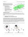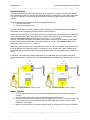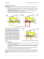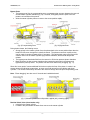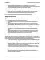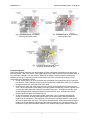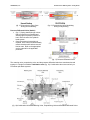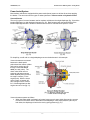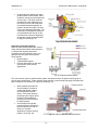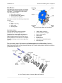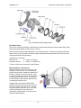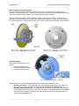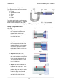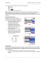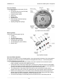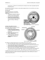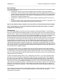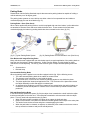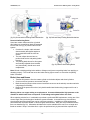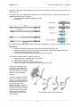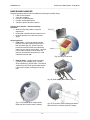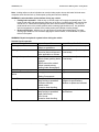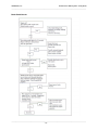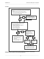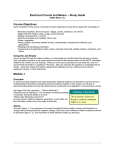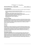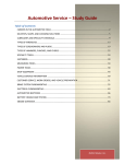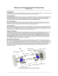
1
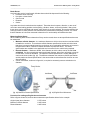
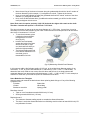
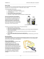
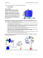
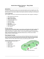
Introduction to Brake Systems – Study Guide
©2004 Melior, Inc.
____________________________________________________________________________________
Introduction
Everybody knows that when you press your foot on the brake pedal the vehicle is supposed to stop. But
how does the pressure from your foot get to the wheels with enough force to stop a heavy vehicle? In the
following sections, we will study the systems and components required to allow brakes to work effectively.
Course Objectives
Upon completion of this course, technicians should understand and be able to apply their knowledge of:
•
•
•
•
•
•
•
•
•
•
•
•
Brake functions and components
Split hydraulic systems
Master cylinder operations
Balance control systems
Power brake booster systems
Disc brake operation
Micrometer reading
Drum brake operation
Brake fluids
Brake bleeding operations
Brake lines and hoses
Basic diagnosis
Using the Job Sheets
As you proceed through the online module, on some pages you will find links that will open a window with
a printable procedure or job sheet containing hands-on lab activities based on the NATEF standards
related to the content you are studying. When you come upon a procedure or job sheet link, click on it
and print the job sheet for completion in the shop. See your instructor for guidance in completing the job
sheets. Some jobs sheets will require supplemental materials such as a vehicle service manual,
equipment manual, or other references.
Brake System Functions
Automotive brakes are designed to slow and stop a vehicle by transforming kinetic (motion) energy into
heat energy. As the brake linings contact the drums/rotors they create friction which produces the heat
energy. The intensity of the heat is proportional to the vehicle speed, the weight of the vehicle, and the
quickness of the stop. Faster speeds, heavier vehicles, and quicker stops equal more heat.
Automotive brake systems can be broken down
into several different sub-systems (fig. 1):
• Apply system
• Boost system
• Hydraulic system
• Wheel brakes
• Balance control system
• Warning system
(fig. 1) Base Brake Systems
______________________________________________________________________________
©2004 Melior, Inc.
Introduction to Brake Systems – Study Guide
_____________________________________________________________________________________________
Base brake components are the parts of the
brake system commonly found on all vehicles.
The term ''base brakes'' does not include either
Antilock or Traction Control systems. Base
brake components include:
• Brake pedal and linkage
• Power assist system
• Master cylinder, hoses and lines
• Brake rotors and pads
• Brake drums and shoes
• Balance controls (proportioning valve
and metering valve), if equipped
• Brake pressure and other warning
systems
• Parking brake pedal and linkage
(fig. 2) Base Brake Components
Split Hydraulic Systems
A partial loss of brake pressure makes it difficult or even impossible to apply the brakes. Therefore,
federal law requires that all vehicles have two separate and independent hydraulic systems. In this way,
the failure of one system will not result in a complete brake loss even though braking will still be severely
reduced.
The two split systems used almost exclusively are:
• Diagonally split – used on most front wheel drive vehicles
• Front/rear split – used on most rear wheel drive vehicles
On a diagonally-split system (fig. 3), the left-front and right-rear brakes (LF/RR) are connected to one
channel of the master cylinder while the right-front and left-rear brakes (RF/LR) are connected to the
other channel of the master cylinder. This system is typically installed on front wheel drive vehicles
because they have a front-heavy weight distribution and approximately 70% of the braking occurs at the
front brakes. As such, if one part of a diagonal system failed, the overall braking would only be reduced
to 50% rather than to 30% if both front brakes were lost. Diagonally-split systems also use proportioning
valves either in the master cylinder circuits or in the rear brake lines to maintain the proper front to rear
pressure balance. Proportioning valves will be covered in a later section.
On a front/rear split system (fig. 4), both front wheel brakes work together on one system (channel) while
both rear wheel brakes work together on a separate system.
(fig. 3) Diagonally-split Hydraulic System
(fig. 4) Front/Rear Split Hydraulic System
_____________________________________________________________________________________________
-2-
©2004 Melior, Inc.
Introduction to Brake Systems – Study Guide
_____________________________________________________________________________________________
Hydraulic System
An important hydraulic principle states that fluids do not compress or produce any measurable friction.
Also, fluid pressure does not diminish when transferred within a closed system. That means that if there
is no leak in a system, the pressure at the wheels will be the same as the pressure from the master
cylinder.
A second hydraulic principle states that a relationship exists between:
• Force and piston area
• Piston travel and piston area
From the first principle, if a master cylinder generates 500 psi, it also transfers 500 psi to the pistons in
each wheel cylinder (remember that fluid pressure remains constant).
In the second principle (fig. 5), when pressure from a one-square-inch master cylinder piston exerts 500
psi on a wheel cylinder piston, which also has one-square-inch surface area, the wheel cylinder piston
transfers 500 pounds of force to the brake shoe (500 psi x 1 in. sq. = 500 lbs.)
However, if the same one-square-inch master cylinder piston exerts 500 psi on a wheel cylinder piston
that has a two-square-inch area, the wheel cylinder piston will transfer 1,000 pounds of force to the
brake lining (500 psi x 2 in. sq. = 1 ,000 lbs.)
Additionally, different piston sizes not only affect the amount of brake force applied, they also determine
the travel distance of the different pistons. For instance, if the one-square-inch master cylinder piston
moves one inch, a one-square-inch wheel cylinder piston will also move one inch (with the same force)
(fig. 5).
If that same one-square-inch master cylinder piston moves one inch, then a two-square-inch wheel
cylinder piston (twice the size) will move just one-half inch (half the distance) but with twice the force (fig.
6)
(fig. 5) Piston Area and Travel (1 inch)
(fig. 6) Piston Area and Travel (1/2inch)
Master Cylinder
•
•
•
•
Converts mechanical force from the brake pedal, power booster and push rod into hydraulic
pressure
Contain pistons, piston seals, return springs and internal brake fluid ports.
Also has a fluid reservoir that may either be an integral part of the unit or remotely mounted. The
reservoir itself will have a removable cap with a rubber diaphragm seal that must be in good
condition to seal properly.
Most reservoirs also have a low brake fluid level switch to alert the driver of a low fluid condition.
_____________________________________________________________________________________________
-3-
©2004 Melior, Inc.
Introduction to Brake Systems – Study Guide
_____________________________________________________________________________________________
The Master Cylinder in Action
As you can see in figure 7 there are two pistons (primary and secondary) and two springs inside the
master cylinder.
• When the brake pedal is pressed, a push rod moves the primary piston forward which begins to
build pressure in the primary chamber and lines. As the brake pedal is depressed further, the
pressure continues to increase.
• Fluid pressure between the primary and secondary piston then forces the secondary piston
forward and pressurizes the fluid in the secondary circuit.
• If the brakes are operating properly, the pressure will be the same in both circuits.
(fig. 7) Brakes released (left); Brakes applied (right)
If there is a leak in one of the brake circuits, that
circuit will not be able to maintain pressure.
Figure 8 shows what happens when one of the
circuits develops a leak. In this example, the
leak is in the primary circuit and the pressure
between the primary and secondary pistons is
lost. This pressure loss causes the primary
piston to mechanically contact the secondary
piston and the master cylinder now behaves as
if it has only one piston. The secondary circuit
will continue to function correctly, however the
driver will have to press the pedal further to
activate it. In addition, since only two wheels
now have pressure, the braking power will be
reduced.
(fig. 8) Master Cylinder with a Primary Circuit Leak
Compensating Ports
• Small holes that are located between the master cylinder reservoir and the front side, or pressure
side, of the master cylinder pistons
• When the master cylinder pistons are in the at-rest position (no braking-figure 9), the piston seals
uncover the compensating ports and open the passages between the reservoir and the wheel
brake channel.
• Allow for the normal expansion and contraction of brake fluid due to changes in temperature
• Assist in fluid return after brake release (See Bypass Port section below)
Note: When the brakes are released, the piston seals on both the primary and secondary pistons are
located between the compensating port and the bypass port. During braking, the piston seals close the
compensating port passages to the reservoir which prevents high pressure fluid from entering the
reservoir
_____________________________________________________________________________________________
-4-
©2004 Melior, Inc.
Introduction to Brake Systems – Study Guide
_____________________________________________________________________________________________
Bypass Ports
• The bypass ports, like the compensating ports, are passages that are open between the reservoir
and the master cylinder chambers (fig. 10). However, the bypass ports are open to the lowpressure or back side of the pistons.
• Allow the master cylinder pistons to return to the at-rest position rapidly.
(fig. 9) Compensating Ports
(fig. 10) Bypass Ports
During brake release, the following occurs:
• Strong springs in the master cylinder force the pistons back to the at-rest position faster than the
brake fluid can return through the hydraulic channels. The pistons must return rapidly so they
can be ready for another forward stroke, if necessary. This rapid piston return movement could
create a vacuum in the master cylinder high pressure chambers, which would delay brake
release.
• The bypass ports allow brake fluid from the reservoir to fill the low-pressure piston chambers.
• Brake fluid from the low pressure chambers then passes through holes in the pistons and
bypasses the piston lip seals. The pistons can then return without any “dragging” (fig. 11).
Since this “return action” causes additional fluid to be moved to the front of the piston, it results in an
excess amount of fluid being present there, as even more fluid returns from the calipers and wheel
cylinders. This excess fluid is easily returned to the reservoir through the now-open compensating ports.
Note: “Piston dragging” can also occur if the seals are installed backward.
(fig. 11) Master Cylinder Return Operation: applied (left); releasing (right)
Residual Check Valve (drum brakes only)
• Included in the master cylinder
• Located in the ports where the brake lines connect to the master cylinder
_____________________________________________________________________________________________
-5-
©2004 Melior, Inc.
Introduction to Brake Systems – Study Guide
_____________________________________________________________________________________________
•
•
•
Maintain a small amount of residual pressure in the brake lines and wheel cylinders
That pressure is then used to hold the wheel cylinder cups tightly against the cylinder and prevent
air from being pulled past the cylinder cups as the brakes are released.
Not used on disc brakes, as they would cause the disc brake pads to drag upon release
Master Cylinder Leaks
Master cylinders are subject to two types of leaks – External and Internal:
• External leaks - brake fluid can usually be seen running down the face of the power booster.
• Internal leaks - the brake pedal will usually fall away when foot pressure is applied.
Refer to specific vehicle information for leak diagnostics and servicing procedures.
Balance Control Systems
Many late model vehicles are equipped with front disc brakes and rear drum brakes and are generally
heavier in the front than in the rear. As a result, different pressures are sometimes required between the
front and rear to ensure even braking. These are some of the items to be aware of concerning this
“braking differential”:
• Disc brakes can apply at lower pressures that drum brakes.
• Metering valves are used to prevent the front disc brakes from applying before the rear drum
brakes.
• If the same hydraulic pressure is simultaneously applied to both the front disc and rear drum
brakes during heavy brake application, the rear brakes can lock up, resulting in a skid and loss of
vehicle control.
• Proportioning valve(s) are used to prevent rear brake lockup by limiting hydraulic pressure to the
rear brakes during heavy braking.
• The metering valve and the proportioning valve are often housed in a single unit, called a
combination valve, in many rear-wheel-drive vehicles equipped with front disc and rear drum
brakes.
• Most vehicles are equipped with some form of pressure differential valve and switch which will
activate a dashboard warning light if pressure is lost in either of the hydraulic channels. This
switch is typically located in a combination valve or on the master cylinder.
Metering Valve
As a result of their design, rear drum brake shoes must move a greater distance to apply as compared to
disc brake pads. If the same pressure were applied to both the front disc and rear drum brakes, at the
same time, the front discs would “catch” much sooner than the rears and cause the vehicle to be thrown
forward. Metering valves are therefore used to compensate for this condition by blocking fluid pressure to
the front disc brakes until the rear shoes have had time to make contact with the drums.
• As the brakes are first applied, fluid pressure rises above a calibrated value (approximately 25 psi
- figure 12) which closes the metering valve stem and blocks the fluid pressure from reaching the
front disc brakes. However, fluid pressure is still applied to the rear brakes, which move the
shoes out to contact the drums.
• Once the shoes begin to contact the drums, the pressure in the rear brake system starts to rise
dramatically. After the pressure reaches a second calibrated value (about 100 psi - figure 13) the
metering valve opens and begins to apply the front disc brakes.
• As the brakes are released and the system pressure again drops below 25 psi, the valve stem
reopens to allow fluid to return to the master cylinder (fig. 14). Notice also in figures 12 through
14 that there is a difference between the valve stem and the valve itself. Each is operated by a
separate spring and has a separate function.
Note: The two pressure points (25 psi & 100 psi in this example) are calibrated based on the size
and weight of a particular vehicle. Metering valves are not universally interchangeable even
though they may appear to be identical.
_____________________________________________________________________________________________
-6-
©2004 Melior, Inc.
Introduction to Brake Systems – Study Guide
_____________________________________________________________________________________________
(fig. 12) Brakes Applied (over 25 psi),
metering valve stem closed
(fig. 13) Brakes Applied (over 100 psi),
metering valve open
(fig. 14) Brakes Released (below 25 psi),
metering valve stem is open
Proportioning Valve
Under heavy braking conditions, rear drum brakes are more susceptible to premature lock-up than the
front disc brakes. Part of the reason is that rapid braking forces tend to pitch the vehicle forward which, in
turn, reduces the weight on the rear wheels. Reducing the weight on the rear wheels increases the
likelihood of lock-up. Proportioning valves are therefore used in the rear hydraulic circuit(s) to help
prevent this sort of premature lock-up.
• During normal braking, or when the brakes are first applied, the proportioning valve is open and
has no effect. Fluid enters the valve through the end with the smaller piston area (fig. 15), passes
through the small bore, and exits to the rear brakes.
• Notice that the outlet end of the valve piston has a larger surface area than the inlet end of the
valve. When fluid pressure rises rapidly in the valve (under hard braking), it exerts a greater force
on the larger outlet piston than it does on the smaller inlet piston. This action moves the valve,
against spring pressure, toward the inlet and closes the center valve. With the valve closed,
pressure to the rear brakes is blocked (fig. 16).
• As the inlet pressure from the master cylinder continues to rise, it eventually becomes high
enough to overcome the larger outlet piston and the valve opens again, allowing additional
pressure to the rear brakes. The reopening of the valve then increases pressure on the outlet
side, which again closes the valve. This cycle is repeated several times a second and keeps the
pressure to the rear brakes proportionately less than the pressure to the front disc brakes. The
proportional cycling action therefore makes for more positive braking under adverse conditions.
_____________________________________________________________________________________________
-7-
©2004 Melior, Inc.
Introduction to Brake Systems – Study Guide
_____________________________________________________________________________________________
(fig. 15) Proportioning Valve Open
During Normal Braking
(fig. 15) Proportioning Valve Modulating
During Heavy Braking
Pressure Differential Valve (Switch)
• (fig. 17) Spring-loaded plunger valves
that are used to turn on dashboard
warning lights if hydraulic pressure is
lost in either channel of a hydraulic
brake system
• Once the pressure loss problem is
repaired, some valves will automatically
reset themselves while others must be
bled to reset. Refer to the appropriate
service material for the applicable
procedure.
(fig. 17) Pressure Differential Valve
The metering valve, proportioning valve, and the pressure differential switch are sometimes housed
together in a single unit called a combination valve (fig. 18). Combination valves are used only on
Front/Rear split brake systems.
(fig. 18) Combination Valve with Metering Valve, Proportioning Valve and Pressure Differential Valve
_____________________________________________________________________________________________
-8-
©2004 Melior, Inc.
Introduction to Brake Systems – Study Guide
_____________________________________________________________________________________________
Power Assist System
Most modern vehicles are equipped with a power assist (boost) system to aid the driver when applying
the brakes. The two most common types of assist systems are vacuum assist and hydraulic assist.
Vacuum Booster
The two (2) types of vacuum boosters used on modern vehicles are the single-diaphragm (fig. 19) and the
tandem-diaphragm (or dual-diaphragm) booster (fig. 20). Both booster types operate similarly but the
tandem-diaphragm booster is smaller in diameter and is used on vehicles where space is critical.
(fig. 19)
(fig. 20)
For simplicity, we will refer to a single-diaphragm vacuum brake booster in this example.
Vacuum boosters are mounted
between the brake pedal
pushrod and the master cylinder
and receive engine vacuum
through a hose and check
valve (one way valve). The
check valve holds vacuum
pressure and assures power
assist capability during times of
low engine vacuum (i.e. the
engine quits). With the check
valve in place, a booster will
have enough reserve vacuum
for 2-3 brake applications after
engine vacuum is lost (fig. 21).
(fig. 21) Booster at Rest with Vacuum
on Both Sides of Diaphragm
Vacuum boosters operate as follows:
• When the brake pedal is released, an internal vacuum port is open which allows engine vacuum
to flow from the check valve to both sides of the diaphragm. With equal pressure (vacuum) on
both sides, the diaphragm is held to the rear by spring pressure (fig. 21).
_____________________________________________________________________________________________
-9-
©2004 Melior, Inc.
Introduction to Brake Systems – Study Guide
_____________________________________________________________________________________________
•
As the brakes are applied, the brake
pedal pushrod moves forward, which
closes the vacuum port and opens the
air inlet valve. This action seals off
the backside of the diaphragm from
the vacuum source and at the same
time allows filtered atmospheric air
pressure to pass through the air inlet
valve to the diaphragm backside. The
combination of atmospheric pressure
on the backside and vacuum on the
front side then moves the diaphragm
and master cylinder pushrod forward
to apply the brakes (fig. 22).
(fig. 22) Vacuum Port Closed
Hydraulic Assist Boost System
Hydraulic brake assist systems are used on
many vehicles with limited underhood space
or vehicles with engines that cannot
consistently produce sufficient vacuum to
operate a vacuum power boost system.
These include:
• Diesel engines
• Turbocharged engines
• Engines that operate at high load
(low vacuum) such as truck
applications.
(fig. 23) Hydraulic Assist System
The most common type of hydraulic-assist system uses pressure from the power steering pump to
provide power brake assist. Power steering pump pressure is used to both help apply the brakes and
also to charge an accumulator for engine-off assist (fig. 23).
•
•
When hydraulic pressure fills
an accumulator, it pushes a
rubber seal against a piston
and collapses the internal
spring. If the power steering
pump stops (the engine quits),
the spring will expand and
push the fluid into the booster
for braking assist.
Accumulators can typically
provide sufficient (emergency)
hydraulic pressure for two or
three (2 or 3) brake
applications if power steering
pressure is lost (fig. 24).
(fig. 24) Hydraulic Booster with Accumulator
_____________________________________________________________________________________________
- 10 -
©2004 Melior, Inc.
Introduction to Brake Systems – Study Guide
_____________________________________________________________________________________________
Disc Brakes
Disc brakes are used on the front of all modern
vehicles, while some have both front and rear
disc brakes. The advantages of disc brakes
over drum brakes include:
• Better fade resistance
• Reduced pulling and grabbing
• Self-adjustment capability
Disc brakes consist of the following components
(fig. 25):
• Rotor
• Hub
• Caliper assembly
• Brake pads
• Mounting bolts
Disc Brake Caliper
The disc brake caliper converts hydraulic
pressure from the master cylinder to a
mechanical force that pushes the brake pads
against the rotor. The caliper body is a Ushaped casting mounted over the rotor and is
typically made of iron or aluminum. All calipers,
regardless of design, contain these major parts
(fig. 26):
(fig. 25) Principle Parts of a Disc Brake
•
•
•
•
•
•
•
•
Caliper body or housing
Internal hydraulic passages
One or more pistons
Piston seals
Dust boots
Bleeder screw
Inboard and outboard disc pads
Mounting bolts
The most common types of disc brakes are the floating caliper and the sliding caliper. Both the
floating and sliding calipers operate identically and the only difference is in the mounting. Specifically,
floating calipers slide on mounting bolts and bushings (fig. 26) while sliding calipers operate on machined
guides and bushings (fig. 27).
(fig. 26) Floating Caliper on Mounting Bolts and Bushings
_____________________________________________________________________________________________
- 11 -
©2004 Melior, Inc.
Introduction to Brake Systems – Study Guide
_____________________________________________________________________________________________
(fig. 27) Machined Guide Sliding Caliper
Disc Brake Rotors
The rotor (or rotor/hub assembly) is attached to the wheel and provides the friction surface that the disc
brake pads clamp against to slow and stop a vehicle.
Rotors must be machined and maintained to very close tolerances. Those that are warped (excessive
lateral runout) or have excessive thickness variation (different thicknesses around the rotor) can cause
vibrations and shutter during braking.
Typical Rotor Tolerances: *
Lateral runout
0 – 0.003 in. (0.08 mm)
Thickness variation
0 - 0.0001 in. (0.00254 mm)
* Refer to vehicle service manual for specifications.
Measuring Rotor Lateral Runout
Excessive heat can cause rotors to warp. This
warpage, or lateral runout, can cause braking
problems and must be measured to determine if
turning, or cutting, the rotors is required. With
the rotor mounted on the vehicle, a dial indicator
is used to determine the runout. The amount
the dial indicator needle deflects while the rotor
is rotated is the lateral runout.
Suppose that in figure 28 the dial indicator
needle moved left -0.002 inch (0.051 mm) and
then right + 0.003 inch (0.076 mm). The total
runout is therefore 0.005 inch (0.127 mm) and
could indicate that the rotor needs to be
refinished or replaced (refer to vehicle service
manual for specifications).
(fig. 28) Lateral Runout Measurement
_____________________________________________________________________________________________
- 12 -
©2004 Melior, Inc.
Introduction to Brake Systems – Study Guide
_____________________________________________________________________________________________
Measuring Rotor Thickness Variation
Rotors must be measured for thickness variation if the customer is experiencing a problem with a
vibrating or pulsating brake pedal. Thickness variations can be caused by excessive heating and cooling
of the rotor, and even a small variation can cause an adverse braking condition.
Precision brake micrometers must be used when measuring the thickness variation of brake rotors. A
difference of more than 0.0003 inch (0.0076 mm) between four measurements (fig. 30) may require that
the rotor be refinished or replaced during brake service (refer to vehicle service manual for specifications).
(fig. 29)
(fig. 30)
Rotor Refinishing
Rotors should be refinished only in
cases of:
• Excessive lateral runout
• Excessive thickness variation
• Excessive surface scoring
(fig. 31) Discard Dimension on a Rotor
Additionally, there are two specifications that must be observed when refinishing rotors:
• Discard specification – This specification is usually stamped or cast into the rotor. Rotors can
be reused to this ‘minimum thickness’ specification if the rotor is not refinished (fig. 31).
• Minimum refinish specification – This specification is found in the vehicle service manual and
is the minimum thickness to which a rotor can be refinished. The difference between the discard
and refinish specifications is to allow for the wear that takes place as the new pads burnish, or
wear into, the refinished rotor.
_____________________________________________________________________________________________
- 13 -
©2004 Melior, Inc.
Introduction to Brake Systems – Study Guide
_____________________________________________________________________________________________
Reading a 0 to 1 Inch English Micrometer
The major components of a micrometer are
(fig. 32):
• Frame
• Spindle and Thimble
• Sleeve
• Anvil
• Ratchet
• Locknut
The spindle and thimble are made together
and are threaded into the sleeve. When the
thimble is rotated the thimble and spindle
move in or out on precision threads (fig. 32).
(fig. 32) Major Parts of an English Micrometer
Reading an English Micrometer
A “One Inch” micrometer always measures a fraction of one (1) inch and measurements are made in four
easy steps.
• Step 1- Read the largest number
that is exposed on the sleeve as
shown at right. In this case the
largest number exposed is 2.
Record this value in step 1 as 0.2
inch (200/1000 inch).
Step 1
•
Step 2- Count the number of marks
that are exposed to the right of the
number 2 as shown. Each mark
equals 0.025 inch. In this example,
one mark is exposed for a total of
.025 inch (1 X 0.025 = 0.025).
Record this in step 2 as 0.025 inch
(25/1000 inch).
Step 2
•
Step 3- Next we find the line
number on the thimble that aligns
with, or is just below, the horizontal
line on the sleeve. The sleeve line
in this example is between 15 and
16. Record this in step 3 as 0.015
inch (15/1000 inch).
Step 3
•
Step 4- The Vernier Scale, for the
most precise measurement, is
located on top of the sleeve. Look
for the one Vernier line that most
perfectly aligns with any line on the
thimble. In this case, Vernier line
number 3 aligns with the thimble
most closely. Record this in step 4
as 0.0003 inch (3/10,000 inch).
Step 4
_____________________________________________________________________________________________
- 14 -
©2004 Melior, Inc.
Introduction to Brake Systems – Study Guide
_____________________________________________________________________________________________
Now we simply total the numbers recorded in step 1 through step 4.
Step 1 0.2
Step 2 0.025
Step 3 0.015
Step 4 0.0003
Total = 0.2403 inch (2403/10,000 inch)
Note: This example was performed with a one inch micrometer for demonstration purposes. If the
micrometer being used on a crankshaft journal, for instance, were a 4 inch tool, then the measurements
would be performed exactly as shown above except that three inches would be added to the
measurement total. Likewise, a 2 inch micrometer would add one inch, a 3 inch micrometer would add 2
inches, etc.
Reading Metric Micrometers
Reading a metric micrometer is similar to
reading an English micrometer except that there
are typically only three readings instead of four.
• On a metric micrometer the upper scale
of the sleeve measures in 1.0 mm
increments while the lower scale
measures 0.5 mm increments.
• The thimble is divided into fifty (50)
equal parts of 0.1 mm each, which
means that one (1) complete revolution
of the thimble equals 0.5 mm.
• Note that metric micrometers do not
have a Vernier scale.
• In the example shown here, the upper
scale reads 5.0 mm, the lower scale
reads 0.5 mm and the thimble reads
0.28 mm for a total of 5.78 mm (5.0 +
0.5 + 0.28 = 5.78 mm).
Step 1
Step 2
Step 3
Drum Brakes
A drum brake unit consists of two brake shoes mounted on a stationary backing plate. When the brake
pedal is pressed, a hydraulically activated wheel cylinder pushes the shoes out to contact a rotating drum
which creates friction and slows the vehicle. As the pedal is released, return springs retract the shoes to
their original position.
• Late model vehicles that use drum brakes will have them only on the rear wheels.
• The two most common types of drum brakes that we will deal with are duo-servo and leadingtrailing.
_____________________________________________________________________________________________
- 15 -
©2004 Melior, Inc.
Introduction to Brake Systems – Study Guide
_____________________________________________________________________________________________
Duo-servo Brakes
Consist of the following components (fig. 38):
• Brake drum
• One primary shoe and one secondary
shoe with friction linings
• Hydraulic wheel cylinder
• Anchor pin
• Backing plate
• Adjusting screw
• Return springs, hold down springs,
connecting springs
• Adjusting linkages and springs
(fig. 38) Duo-servo Drum Brake
Wheel Cylinders
Consist of the following parts (fig. 39):
• Cylinder
• Two pistons
• Two lip seal piston cups
• Expander spring assembly
• Two protective dust covers
• Two actuating pins (some models)
• Bleeder valve
(fig. 39) Wheel Cylinder
Duo-servo Brake Operation
When duo-servo brakes are in the released position, return springs hold the bottoms of the shoes against
the adjusting screw while the tops of the shoes are held against the anchor pin. As the brake pedal is
pressed, the following occurs (fig. 38):
• Hydraulic pressure from the master cylinder to the wheel cylinder forces both wheel cylinder
pistons outward to press the shoes against the drum.
• As the brake shoes contact the rotating drum, frictional force causes both shoes to rotate slightly.
This action causes the secondary shoe (the one toward the rear of the vehicle) to jam against the
anchor pin and forces the wheel cylinder piston back into the wheel cylinder.
• The rotating action of the primary brake shoe (the front one) causes the secondary shoe to
wedge into the drum with a force that is greater than the just the hydraulic pressure would cause.
• Because of the wedging action, both shoes must be pulled away from the drum (by the return
springs) when the brakes are released. Additionally, there are other springs that hold the brake
shoes in place and return the adjuster arm after it actuates (fig. 38).
• As a result of this design, the secondary shoes must perform more of the braking than the
_____________________________________________________________________________________________
- 16 -
©2004 Melior, Inc.
Introduction to Brake Systems – Study Guide
_____________________________________________________________________________________________
primary shoes. Therefore, the secondary shoes usually wear more and are typically larger than
the primary shoes.
As a general rule-of-thumb, the heavier a drum-brake-equipped vehicle is, the more likely it is to have a
duo-servo brake system.
Self-adjusters
Drum brake systems have a self-adjust
capability to compensate for wear on the
brake shoes.
• Self-adjuster mechanism consists of
a series of links, springs, retainers
and a star wheel (screw) adjuster.
• Rotational action of the brake shoes
activates the self-adjuster linkage
when the brakes are applied and the
vehicle is moving in reverse (fig.
41).
(fig. 41) Brake Adjuster Operation (duo-servo)
Leading-trailing Brake Operation
Three major differences between duo-servo
and leading-trailing drum brakes:
1) Leading-trailing systems have the
anchor pin mounted at the bottom of
the backing plated rather than at the
top (fig. 42).
2) Neither shoe pushes against the
other in leading-trailing.
3) Leading-trailing drum brakes are
automatically adjusted when the
parking brake is applied and
released.
(fig. 42) Typical Leading-trailing Brake
The operation of leading-trailing brakes is much simpler than duo-servo systems:
• When the brake pedal is pressed, a wheel cylinder pushes equally on each brake shoe.
• In turn, this forces the top of each shoe outward toward the drum, and each shoe pivots on the
anchor located at the bottom of the backing plate.
• Drum friction pulls the leading (forward) shoe into tighter contact with the drum and aids the
hydraulic force of the wheel cylinder. This action provides most of the braking force.
• The secondary shoe is not self-energizing as in Duo-servo but does provide some braking force
due to the action of the wheel cylinder. When backing up, the opposite action takes place.
In leading-trailing systems both the primary and secondary brake linings are typically identical in size. As
a general rule-of-thumb, the lighter a drum-brake-equipped vehicle is, the more likely it is to have a
leading-trailing brake system.
_____________________________________________________________________________________________
- 17 -
©2004 Melior, Inc.
Introduction to Brake Systems – Study Guide
_____________________________________________________________________________________________
Brake Drums
Any time brake service is performed, all brake drums should be inspected for the following:
• Excessive wear or scoring
• Hot spots or heat checks
• Out-of-round
• Distortion
• Cracks
Any brake drum that is cracked must be replaced. Those that have hot spots, distortion, or are out-ofround can cause braking problem such as pulling, vibration, chatter, noise and pulsation. Many times
these drums can be refinished and reused, other times they must be replaced. Drums that exhibit minor
scoring but have no other problems can sometimes be reused without refinishing; however, it is critical
that the diameter of a drum be measured to determine if it can be safely refinished and reused.
Measuring Brake Drums
When measuring brake drums to determine if they can be reused, there are two specifications that must
be understood.
• Maximum refinish diameter – the maximum diameter to which a drum can be turned and still be
reinstalled on a vehicle. The maximum refinish diameter specification lets the technician know
that there is enough material remaining on the drum to be used safely and without an increase in
the potential for failure. Maximum refinish diameters vary between drums. The actual
specifications are available in the applicable service manual for the vehicle being repaired.
• Discard diameter – ‘Maximum discard’ is the diameter to which a drum can be reused if not
refinished. If a drum exceeds the maximum discard diameter, either from refinishing or through
normal wear, it must be discarded. The maximum discard specification is usually stamped or
cast into the drum surface (fig. 43). The difference between the maximum refinish specification
and the maximum discard specification is the amount that must be allowed for the drum to wear
after refinishing.
• A drum micrometer, as shown in figure 44, is required to accurately measure a brake drum’s
diameter.
(fig. 43) Maximum Discard Specification
(fig. 44) English Drum Micrometer
Procedure for reading an English drum micrometer
Refer to figures 44 and 45, and use the measurement specifications below for the example:
Original (new) drum diameter
Maximum refinish diameter
Discard diameter
11.375 inches
11.435 inches
11.465 inches
_____________________________________________________________________________________________
- 18 -
©2004 Melior, Inc.
Introduction to Brake Systems – Study Guide
_____________________________________________________________________________________________
•
•
•
Move the anvil leg of the drum micrometer along the graduated shaft until the “whole” number of
the drum diameter (in this example, 11) is aligned on the shaft. Tighten the lock screw.
Next, move the dial indicator leg along the graduated shaft until the “whole” number of the drum
diameter (11) is aligned on that side.
Now, move the dial indicator three (3) additional notches outward (you will feel a click at each
notch) and tighten its lock screw.
Note: Each notch is equal to precisely 1/8 (0.125) inch and also aligns with a mark on the shaft.
Therefore 3 notches are equal to 3 x 0.125 inch = 0.375 inch.
The drum micrometer is now set to the new drum diameter of 11.375 inches. In actual use, it may be
necessary to move the dial indicator leg one notch in either direction from this point since all new drums
don’t come in increments of .125 inch.
• To use the micrometer, place
it inside the drum and hold it
flat against the rim of the
drum (fig. 45).
• Hold the anvil end steady
against the inside of the drum
and move the dial, or right
end, back and forth slowly to
obtain the highest reading.
• The highest reading achieved
is the amount that the drum is
oversized, given in
thousandths of an inch.
(fig. 45) Measuring a Brake Drum Diameter
In this case we add the dial indicator reading, 0.015 inch, to the original drum diameter setting of our
micrometer, 11.375, to get our total diameter of 11.390 inches (11.375 + 0.015 = 11.390 inches). To
determine how much metal we can remove from this drum and still use it, we simply subtract the
measured diameter from the maximum refinish diameter (11.435 – 11.390 = 0.045). For this example, a
maximum of 0.045 inch (or 45/1000 inch) can be machined from the drum.
Some Brake Service Thoughts
Always inspect and measure the brake drums when replacing brake linings or if any of the following
symptoms occur:
-Pulsation
-Brake fade
-Chatter
-Wheel drag
-Brakes too sensitive
-Spongy pedal
Resurface drums if:
• Taper or out-of-roundness exceeds 0.006 inch (0.15 mm)
• Scoring exceeds 0.060 inch (1.52 mm)
Replace drums if:
• The maximum diameter reading equals or exceeds the discard dimension.
• The drum is under the discard dimension but refinishing would not leave at least 0.030 inch (0.76
mm) allowance for wear.
_____________________________________________________________________________________________
- 19 -
©2004 Melior, Inc.
Introduction to Brake Systems – Study Guide
_____________________________________________________________________________________________
Brake Fluid
The specifications for all automotive brake fluids are defined by the Federal Motor Vehicle Safety
Standards and are assigned Department of Transportation (DOT) numbers.
Qualities that brake fluid must have:
• Free flowing at low and high temperatures
• A boiling point over 400 degrees F. (204 degrees C.)
• Low freezing point
• Non-corrosive to metal or rubber brake parts
• Ability to lubricate metal and rubber parts
• Hygroscopic - Ability to absorb moisture that enters the hydraulic system
The three (3) brake fluids currently assigned
DOT numbers are DOT 3, DOT 4 and DOT 5.
DOT 3 and DOT 4 are polyalkylene-glyco-ether
mixtures while DOT 5 is silicone based. All
domestic and most import car manufacturers
specify and require DOT 3 brake fluid (some
imports require DOT 4 as it has a higher boiling
point). DOT 5 brake fluid is not currently used in
any domestic or import vehicles (fig. 46).
(fig. 46) DOT 3 and DOT 4 Brake Fluids
Precautions must always be observed when working with brake fluids:
• Brake fluid is toxic to the human body.
• Brake fluid can damage painted surfaces.
• Brake fluid contaminated with moisture, dirt, petroleum or other foreign material will damage the
hydraulic system internally.
• Only denatured alcohol or other approved cleaners should be used when cleaning brake
hydraulic parts.
• Use only fresh, clean brake fluid (never reuse old brake fluid).
• Never mix brake fluids with any other fluids, including other types of brake fluid (e.g. DOT 3 and
DOT 4).
Bleeding Brakes
Any time a brake hydraulic system is opened to the atmosphere for repairs or due to a leak, the system
must be bled to remove the air. Unlike brake fluid, air is compressible and can cause a spongy brake
pedal, brake pull and ineffective brake application.
Master Cylinder Bleeding
It is always a good idea to bench bleed a master
cylinder after servicing and before
installing/reinstalling it on the vehicle. One
method for bench bleeding a master cylinder
requires attaching two (2) brake lines to the
master cylinder (fig. 47) and directing them back
into the reservoir. Fill the reservoir(s) with clean
DOT brake fluid and slowly push the master
cylinder pistons in several times until air bubbles
are no longer seen. This procedure will save
time and fluid when bleeding the hydraulic
system after the master cylinder has been
reinstalled.
(fig. 47) Bench Bleeding Master Cylinder
_____________________________________________________________________________________________
- 20 -
©2004 Melior, Inc.
Introduction to Brake Systems – Study Guide
_____________________________________________________________________________________________
The two (2) most commonly used methods for bleeding brakes are:
• Pressure bleeding
• Manual bleeding
Pressure Bleeding
A pressure bleeder is a special tank that is
divided into two (2) chambers by a rubber
diaphragm. The upper chamber is filled with
clean fresh DOT 3 brake fluid while the lower
chamber is pressurized with air. The rubber
diaphragm keeps the brake fluid separated from
the air (fig. 48). Pressure bleeding is often the
preferred method for bleeding brakes since one
person can do the job alone and the master
cylinder does not have to be repeatedly refilled
during the process.
(fig. 48) Typical Brake Pressure Bleeder
Pressure bleeders are attached to the master cylinder with a hose and a special adapter (fig. 49). The
special adapter seals the pressure bleeder to the master cylinder to prevent fluid and air leaking into or
out of the system. To pressure bleed a brake system:
• Fill the pressure bleeder with clean DOT 3 brake fluid and charge the air reservoir with fifteen (15)
to twenty (20) psi (105 – 140 kPa) of air.
• Fill the master cylinder reservoir to the proper level, usually about one quarter (1/4) inch from the
top. Install the bleeder adapter to the master cylinder reservoir, attach the supply hose from the
pressure bleeder to the adapter, and open the supply valve.
• Attach a bleeder hose to the wheel cylinder bleeder valve and extend the end of the hose into a
clear glass container partially filled with DOT 3 brake fluid (fig. 50).
• Open the bleeder valve. Any air trapped in the system can be seen as bubbles escaping from the
bleeder hose. Close the bleeder valve after all air bubbles have been expelled.
• Repeat the bleeding process for all four (4) wheels.
• Remove the pressure bleeding equipment and fill the master cylinder to the proper level. Test the
brakes to make sure the pedal is firm before driving the vehicle.
Note: A valve depressor tool may be required to bleed the front disc brake calipers on vehicles
equipped with a metering valve.
(fig. 49) Pressure Bleeder w/Master Cylinder Adapter (fig. 50) Air Bubbles Bleeding from a Brake System
_____________________________________________________________________________________________
- 21 -
©2004 Melior, Inc.
Introduction to Brake Systems – Study Guide
_____________________________________________________________________________________________
Manual Bleeding
The manual brake bleeding process requires two (2) technicians and the fluid level in the master cylinder
must be checked often.
• Technician # 1 begins the procedure by pressing the brake pedal to build up fluid pressure.
• Technician # 1 then continues to hold a steady pressure on the brake pedal while Technician # 2
opens the bleeder valve and observes as fluid and air bubbles are expelled. The brake pedal will
go to the floor and Technician # 1 will continue to hold steady pressure on the brake pedal until
Technician # 2 closes the bleeder valve.
• This process is repeated until all the air has been expelled. Repeat the process for all four (4)
wheels.
• Check and refill the master cylinder between wheels and when the procedure is completed. Test
the brakes to make sure the pedal is firm before driving the vehicle.
Note: Do not allow the master cylinder to run out of fluid or air will be introduced into the system.
Note: A valve depressor tool may be required to bleed the front disc brake calipers on vehicles
equipped with a metering valve.
Bleeding Order
One of the oldest adages in the automotive service industry involves brake bleeding. The old saying is
that you should bleed the brakes starting farthest from the master cylinder and move progressively closer
with each wheel. However, few understand where this belief originated. As with most firmly held beliefs,
there is some truth in this one, but it is no longer universally applicable as it once was. The history is this;
before front-wheel-drive vehicles became commonplace, most vehicles had rear-wheel-drive and
front/rear split brake systems (at least after the advent of dual-piston master cylinders). In order to bleed
the front brakes, it was necessary to build up enough pressure in the rear brakes to open the metering
valve and allow fluid to reach the fronts. So, technicians would bleed the right-rear first, since it is the
longest brake line, and then move to the left rear. After the rears were clear of trapped air, the fronts
could be bled starting with the longest line (right-front). This system is still applicable today for vehicles
with front/rear split systems. However, it does not apply with diagonally-split systems (mostly front-wheeldrive) for two reasons; 1) diagonally-split systems do not have a metering valve and 2) the right-rear and
left-rear brakes are on separate systems.
If the procedure above is used on a diagonally-split system and the right-rear brake is bled followed by
the left-rear, then the left-front brake portion, which is only half bled (right-rear is done) will tend to aerate
or make bubbles in the fluid as the pedal is pressed to bleed the left-rear. Once you have bubbles in the
fluid, it can be extremely difficult to get the lines clear and you may have to wait for the air and the fluid to
separate again before continuing.
So what is the proper bleeding order to use? It depends on the vehicle. If it is a front-rear split system,
start with one of the rear brakes (it really doesn’t matter which but most people start with the right-rear),
then move to the other rear brake. That will completely bleed that system (the rears). Then bleed the
front brakes. Again the order is really unimportant. If the vehicle has a diagonally split system, you can
begin wherever you like but, and this is important, whichever you do first, the opposite brake must be
next to prevent the possibility of aeration. If the right-rear is first, the left-front must be next. Start with the
right-front? Then the left-rear is second. Most seasoned technicians will typically go from right-rear to
left-front then from left-rear to right-front. That is usually a good idea since a consistent procedure helps
to avoid errors.
Note: because of the nature of some Antilock Brake systems, certain vehicles will use a specific bleeding
order to help ensure that all of the air is removed from that unit. If that is the case, follow the
manufacturer’s instructions.
_____________________________________________________________________________________________
- 22 -
©2004 Melior, Inc.
Introduction to Brake Systems – Study Guide
_____________________________________________________________________________________________
Parking Brake
Federal Motor Vehicle Safety Standards require that automotive parking brakes be capable of holding a
vehicle stationary on a 30 degree grade.
The parking brake systems on most vehicles use either a hand or foot operated lever and cables to
mechanically apply the rear wheel brakes (fig. 51).
Parking Brake - Drum (Duo-Servo)
When a driver applies the parking brake on a vehicle equipped with rear drum brakes, it pulls cables that
are attached to actuator levers and struts inside the brake drum. These actuator levers and struts
mechanically apply the brakes by pushing both brake shoes outward into the drum (fig. 52).
(fig. 51) Typical Parking Brake System
(fig. 52) Parking Brake Strut and Actuator Lever (Duo-Servo)
Disc Brakes with Integral Parking Brake
Many vehicles that are equipped with rear disc brakes require a regular application of the parking brake to
keep the rear disc brakes in proper adjustment. Unlike front disc brakes, rear disc brakes on these
vehicles are not self-adjusting. The two (2) most common types of caliper-actuated parking brakes are
the:
• Screw-and-nut
• Ball-and-ramp
Screw and Nut Parking Brake
When the parking brake is applied on a rear-disc-equipped vehicle (fig. 53) the following occurs:
1. The cable actuated parking brake lever rotates an actuator screw
2. The actuator screw unthreads on a nut inside the piston.
3. As the screw turns, it moves the nut outward by pressing against a cone inside the piston.
4. The piston applies the inboard pad against the rotor. The movement of the piston also causes
the caliper assembly to slide and apply the outboard pad.
5. An adjuster spring inside the nut and cone rotates the nut outward when the parking brakes are
released to provide self-adjustment. Rotation of the nut also takes up clearance as the brake
pads wear.
Ball-and-Ramp Parking Brake
In the ball-and-ramp park brake system (fig. 54) the caliper lever is attached to a shaft inside the caliper
that has a small plate on the other end. A second plate is attached to a thrust screw inside the caliper
piston. Three (3) steel balls separate the two (2) plates.
• When the parking brake is applied, the caliper lever rotates the shaft and plate.
• Ramps on the surface of the plate force the balls outward against similar ramps in the other plate.
• This action forces the thrust screw and piston outward applying the brake.
• When the park brake is released, an adjuster nut inside the piston rotates on the thrust screw to
take up excessive clearance and provide self-adjustment.
_____________________________________________________________________________________________
- 23 -
©2004 Melior, Inc.
Introduction to Brake Systems – Study Guide
_____________________________________________________________________________________________
(fig. 53) Screw-and-Nut Parking Brake Mechanism
Drum-in-Hat Parking Brake
Some later model vehicles with four (4) wheel
disc brakes use a small drum brake incorporated
into the rear rotor (fig. 55) called a drum-in-hat
system.
• Consists of a simple, cable activated
shoe assembly that applies against a
drum machined inside the rotor hat
section
• The rear caliper does not have to
perform both service and parking brake
functions.
• The parking brake shoes for this system
are manually adjusted when installed,
and, theoretically, should never need
readjustment.
(fig. 54) Ball-and-Ramp Parking Brake Mechanism
(fig. 55) Drum-In-Hat Parking Brake
Note: Kinked or binding parking brake cables or linkages could prevent a parking brake from applying or
releasing properly. This could also cause the brake warning light to remain on even after the parking
brake is released.
Brake Lines and Hoses
•
•
•
•
Transfer fluid pressure from the master cylinder to the brake calipers and wheel cylinders
On some vehicles, pressure can exceed 1000 psi.
Brake hoses (the shorter rubber-covered sections that connect at the wheels) must also maintain
a high degree of flexibility.
Because of the pressures involved, only double-walled steel brake tubing is approved for use in
brake lines.
Warning: Never use copper tubing as a replacement. It cannot withstand the high pressure or the
vibration to which brake lines are exposed. Fluid leakage and system failure can result.
When replacing a brake line, it is advisable to purchase a preformed OEM replacement, as they are of the
correct length, bend, and strength to handle the system demands. It can also be more cost-effective,
since bending and flaring brake lines can be quite time consuming. In addition to OEM replacements,
aftermarket lines are also available in various lengths and diameters. Many are also pre-flared and have
flare nuts installed (fig. 56). Aftermarket bulk brake line is also available which can be cut to length and
flared as needed. Keep in mind that this is a job to be performed only by those with the requisite tools
_____________________________________________________________________________________________
- 24 -
©2004 Melior, Inc.
Introduction to Brake Systems – Study Guide
_____________________________________________________________________________________________
and skills. Additionally, care must always be exercised when bending any brake line so as to not kink and
weaken the line.
All vehicles utilize one of two methods of brake line connection flaring (fig. 57) and each requires its own
special tools and flare nuts. They are:
• ISO (International Standards Organization) flare
• Double flare
(fig. 56) Brake Tubing with Flared Ends and Flare Nuts Installed; (fig. 57) ISO and Inverted Double Flares
Brake Hoses
• Designed to distribute high pressure brake fluid to the wheel brakes (fig. 58)
• Must also allow for the vertical movement of the suspension and the side-to-side motion of the
front wheels as the driver steers the vehicle
• These forces are substantial and can weaken the hoses over time.
When performing brake service, always remember to:
• Inspect the hoses for damage, kinks or ballooning
• Inspect hoses for proper routing
• Never hang a caliper from a rubber brake hose
• Replace the copper sealing washers when replacing brake hoses
Defective or damaged hoses
can balloon or swell, which will
store brake fluid pressure and
cause the vehicle to pull during
braking or give a low pedal
concern.
A blocked, restricted, or kinked
brake hose can also cause the
vehicle to pull during braking. In
this case the pull will be to the
opposite direction of the
problem component. That
means that a left-front hose that
is blocked, restricted, or kinked
would cause a pull to the right
and a right-front hose failure
would cause a pull to the left
during braking.
(fig. 58) Brake Hoses and Failure Modes
_____________________________________________________________________________________________
- 25 -
©2004 Melior, Inc.
Introduction to Brake Systems – Study Guide
_____________________________________________________________________________________________
BASE BRAKE DIAGNOSIS
Diagnosing brake problems can be simplified by following a few basic steps:
• Listen to the customer
• Verify the complaint
• Perform a visual inspection
• Conduct a brake pedal check
• Test Drive (before and after repairs)
Listen to the customer…ask the necessary
questions
• What kind of problem did the customer
experience?
• Under what conditions did the problem occur?
• Does the problem occur with every brake
apply?
Visual inspection
• Fluid levels – remove the master cylinder
reservoir cover and inspect the fluid level in
both chambers (fig. 59). Some reservoirs
have both Hot and Cold fill level indications,
make sure you use the correct level. Low fluid
level in either chamber could be either the
result of normal brake lining wear or it could
indicate an external leak.
(fig. 59) Check Fluid Level
•
External leaks – visually check the master
cylinder (fig. 60), calipers (fig. 61), and/or
wheel cylinders (fig. 62) for leaks. Fluid will be
visible on the face of the power brake booster
if the master cylinder is leaking from its rear
seal.
(fig. 60) Fluid Leaking from Master Cylinder
(fig. 61) The bottom of the caliper will be
damp with fluid if a disc brake is leaking.
(fig. 62) The bottom of the backing plate will be
damp with fluid if a wheel cylinder is leaking.
_____________________________________________________________________________________________
- 26 -
©2004 Melior, Inc.
Introduction to Brake Systems – Study Guide
_____________________________________________________________________________________________
Note: Leaking calipers or wheel cylinders can coat the brake pads or shoes with brake fluid and cause
complaints such as wheel lock up, brake squeal, pulling and ineffective braking.
WARNING: Leaks should be repaired before driving any vehicle.
• Parking brake operation – With the key on and the engine off, engage the parking brake. The
brake should apply with approximately half travel of the lever or pedal and the brake warning light
should turn on. Deactivate the parking brake and it should release immediately. The lever or
pedal should return to the release position and the warning light should turn off. Any problems
with the engagement or release of the parking brake could indicate a binding linkage.
• Brake warning light – With the key on and engine off (parking brake disengaged), if a brake
warning light comes on, with or without applying the service brakes, it could indicate a hydraulic
failure in the system.
WARNING: Repair the hydraulic system before driving the vehicle.
Detailed Visual Inspection
Component
Brake pipes and hoses
Parking brake cables
Parking brake operation
Brake linings
Brake hardware and holddowns
Brake Rotors
Brake Drums
Inspect for:
Leaks
Crimps or restrictions
Excessive Slack
Corrosion that could prevent
brake application or release
Proper operation
Wheels rotate (parking brake
engaged
Wheels cannot be rotated
without excessive drag
(parking brake disengaged)
Excessive wear
Damage, wear or corrosion
Missing Components
Wear (reduced thickness)
Deep scoring or scratches
Thickness variation
Lateral runout
Excessive heat checking
Wear (excessive diameter)
Deep scoring or scratches
Taper (bell mouth)
Out of round
Excessive heat checking
Corrective Action
Repair or replace as necessary
Clean, lubricate, adjust or replace
as necessary
Clean, lubricate, adjust or replace
as necessary
Replace
Replace
Replace
Compare to specifications
Machine or replace as indicated
Compare to service limit
specifications
_____________________________________________________________________________________________
- 27 -
©2004 Melior, Inc.
Introduction to Brake Systems – Study Guide
_____________________________________________________________________________________________
Brake Pedal Checks
_____________________________________________________________________________________________
- 28 -
©2004 Melior, Inc.
Introduction to Brake Systems – Study Guide
_____________________________________________________________________________________________
Test Drive
Drive vehicle at low speed (under 20 mph). Brake moderately
to a stop.
• Unusual pedal effort (hard, spongy, grabby)?
• Noises from the brakes (growl, squeal, scrape)?
• Vehicle direction change (pull)?
See symptom chart in the
appropriate service manual.
Note condition and proceed.
No
Yes
Drive vehicle at higher speed (up to 40 mph).
Press the brake pedal with moderate force.
• Brake pedal pulsation?
• Vehicle or steering wheel vibration?
• Noise from the brakes?
• Direction change (pull)?
• Brake warning light on?
Repeat procedure using
the parking brake
mechanism white the
release handle pulled, if
available.
Yes
No
•
•
•
See symptom chart in the
appropriate service manual
Make a detailed visual
inspection.
Make all necessary repairs
before proceeding.
No
Problem is
likely in front
brakes.
•
•
Yes
Problem is
likely in rear
brakes
See symptom tables in the
appropriate service manuals
Make all necessary repairs
Portions of materials contained herein have been reprinted with permission of General Motors
Corporation, Service Operations License Agreement #0410610
_____________________________________________________________________________________________
- 29 -