1
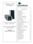
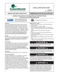
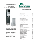
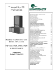
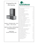
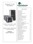
Tranquility® Modular
(817) Vertical Stack
Chassis
Table of Contents
817 Model Nomenclature
2
General Information
3
Cabinet and Chassis Pre-Installation and Chassis
Installation
5
817 Series Wiring Diagram Matrix
6
Wiring Diagrams - 96B0036N18 - P Controls
7
Wiring Diagrams - 96B0036N07 - S Controls
8
Wiring Diagrams - 69358802 - M Controls
Commercial
Vertical Stack
Water-Source
Heat Pump Chassis
for Installation in Existing
ClimateMaster and CHP Cabinets
Installation, Operation
& Maintenance
97B0056N02
Revised: 28 February, 2014
9
Preventive Maintenance
10
Start-up Log Sheet
11
Functional Troubleshooting
12
Troubleshooting Form
14
Warranty
15
Revision History
16
CLIMATEMASTER WATER-SOURCE HEAT PUMPS
817 Chassis
R e v. : 2 / 2 8 / 1 4
817 Model Nomenclature
Chassis
3
4 5
6
7
8
9
10
11
12
13
817
09
G
B
P
S
S
C
S
A
1 2
Revision Level
Series
A = Current Revision Level
817 = TRANQUILITY
HIGH RISE
REPLACEMENT CHASSIS
Standard
S = Standard
A = Special #1
B = Special #2
Etc.....
Unit Size
09
12
24
30
36
Heat Exchanger Options
C = Copper Coax w/Coated Air Coil
N = Cupro-Nickel Coax w/Coated Air Coil
D = Copper Coax w/Coated Air Coil & Insulated Tubing
E = Cupro-Nickel Coax w/Coated Air Coil & Insulated Tubing
F = Copper Coax w/Non-Coated Air Coil & Insulated Tubing
G = Cupro-Nickel Coax w/Non-Coated Air Coil & Insulated Tubing
L = Copper Coax w/Non-Coated Air Coil
M = Cupro-Nickel Coax w/Non-Coated Air Coil
H = Copper, RV Energized in Heating w/Coated Air Coil (Replacement Only)
J = Cupro-Nickel, RV Energized in Heating w/Coated Air Coil
Voltage
E = 265/60/1
G = 208-230/60/1
A
S.S.
Drain
Pan
X
B
1
-
X
2
X
X
OPTION
MUTE
-
Water Valve & Pump Option
S = No Water valve
M = Standard Water Valve (Normally Closed)
Controls
P = Standard (24V N.C. Safeties) for use with CXM or DXM
M = Combination Controls (24V N.C. Safeties) For
use w/either Electro-Mechanical or CMC Controls.
(Compare with Cabinet Decoder for Compatibility)
S = Standard (Line Voltage, Pilot Duty Lock-Out Relay, Original chassis
had N.O. Switches. Replacement has N.C. High Pressure Switch,
Low Pressure Switch or High Discharge Temp Switch, FreezeStat
and Quick Connect cord.
(Compare with Cabinet Decoder for Compatibility)
AUTO-FLOW REGULATOR (US GPM) CODE
5/8 SWEAT
UNIT
09
1.5
UNIT
12
7/8 SWEAT
UNIT
15 & 18
UNIT
30
C
D 2.0
2.0
2.5
2.5
E 2.5
3.0
3.0
F 3.0
3.5
3.5
G 3.5
4.0
4.0
4.0
H
J
5.0
5.0
5.0
5.0
6.0
6.0
6.0
K
7.0
L
7.0
7.0
M
8.0
8.0
9.0
9.0
N
10.0
P
S = STANDARD - NO FLOW REGULATOR
UNIT
24
N/A
N/A
2
UNIT
36
C l i m a t e M a s t e r Wa t e r - S o u r c e H e a t P u m p s
6.0
7.0
8.0
9.0
10.0
3
THE SMART SOLUTION FOR ENERGY EFFICIENCY
817 Chassis
R e v. : 2 / 2 8 / 1 4
General Information
Safety
Warnings, cautions, and notices appear throughout this
manual. Read these items carefully before attempting any
installation, service, or troubleshooting of the equipment.
DANGER: Indicates an immediate hazardous situation,
which if not avoided will result in death or serious injury.
DANGER labels on unit access panels must be observed.
WARNING: Indicates a potentially hazardous situation,
which if not avoided could result in death or serious injury.
WARNING!
WARNING! Verify refrigerant type before proceeding. Units
are shipped with R-410A (EarthPure®) refrigerants. The
unit label will indicate which refrigerant is provided. The
EarthPure® Application and Service Manual should be read
and understood before attempting to service refrigerant
circuits with R-410A.
WARNING!
WARNING! To avoid the release of refrigerant into the
atmosphere, the refrigerant circuit of this unit must be
serviced only by technicians who meet local, state, and
federal proficiency requirements.
CAUTION: Indicates a potentially hazardous situation or
an unsafe practice, which if not avoided could result in
minor or moderate injury or product or property damage.
NOTICE: Notification of installation, operation, or
maintenance information, which is important, but which is
not hazard-related.
WARNING!
WARNING! All refrigerant discharged from this unit must
be recovered WITHOUT EXCEPTION. Technicians must
follow industry accepted guidelines and all local, state, and
federal statutes for the recovery and disposal of refrigerants.
If a compressor is removed from this unit, refrigerant circuit
oil will remain in the compressor. To avoid leakage of
compressor oil, refrigerant lines of the compressor must be
sealed after it is removed.
CAUTION!
CAUTION! To avoid equipment damage, DO NOT use
these units as a source of heating or cooling during the
construction process. The mechanical components and filters
will quickly become clogged with construction dirt and debris,
which may cause system damage.
WARNING!
WARNING! The installation of water-source heat pumps and
all associated components, parts, and accessories which
make up the installation shall be in accordance with the
regulations of ALL authorities having jurisdiction and MUST
conform to all applicable codes. It is the responsibility of
the installing contractor to determine and comply with ALL
applicable codes and regulations.
c l i m a t e m a s t e r. c o m
3
CLIMATEMASTER WATER-SOURCE HEAT PUMPS
817 Chassis
R e v. : 2 / 2 8 / 1 4
Inspection - Upon receipt of the equipment, carefully
check the shipment against the bill of lading. Make sure
all units have been received. Inspect the packaging of
each unit, and inspect each unit for damage. Insure that
the carrier makes proper notation of any shortages or
damage on all copies of the freight bill and completes a
common carrier inspection report. Concealed damage
not discovered during unloading must be reported to
the carrier within 15 days of receipt of shipment. If not
filed within 15 days, the freight company can deny the
claim without recourse. Note: It is the responsibility of the
purchaser to file all necessary claims with the carrier. Notify
your equipment supplier of all damage within fifteen (15)
days of shipment.
Storage - Equipment should be stored in its original
packaging in a clean, dry area. Store chassis in an upright
position at all times. Stack units at a maximum of 2 units high.
Unit Protection - Cover units on the job site with either
the original packaging or an equivalent protective
covering. In areas where painting, plastering, and/or
spraying has not been completed, all due precautions
must be taken to avoid physical damage to the units and
contamination by foreign material. Physical damage and
contamination may prevent proper start-up and may result
in costly equipment clean-up.
Examine all pipes, fittings, and valves before installing
any of the system components. Remove any dirt or debris
found in or on these components.
Prior to flushing risers with water, be sure that the
temperature in building will always be above freezing.
Pre-Installation - Installation, Operation, and
Maintenance instructions are provided with each unit.
The installation site chosen should include adequate
service clearance around the unit. Before unit start-up,
read all manuals and become familiar with the unit and its
operation. Thoroughly check the system before operation.
Check that you have all kits and options required before
starting. Verify electrical service to cabinet is adequate
for new chassis. See electrical data. Upgrade service if
it is needed.
4
Prepare chassis for installation as follows:
1. Verify refrigerant tubing is free of kinks or dents and
that it does not touch other unit components.
2. Inspect all electrical connections. Connections must
be clean and tight at the terminals.
3. Remove compressor shipping clips, bracket, or screws.
See chasss pre-installation section for instructions.
4. If chassis is not installed in cabinet, store in
original carton.
WARNING!
WARNING! Polyolester Oil, commonly known as POE oil, is
a synthetic oil used in many refrigeration systems including
those with HFC-410A refrigerant. POE oil, if it ever comes
in contact with PVC or CPVC piping, may cause failure of
the PVC/CPVC. PVC/CPVC piping should never be used
as supply or return water piping with water source heat
pump products containing HFC-410A as system failures and
property damage may result.
CAUTION!
CAUTION! DO NOT store or install units in corrosive
environments or in locations subject to temperature or
humidity extremes (e.g., attics, garages, rooftops, etc.).
Corrosive conditions and high temperature or humidity can
significantly reduce performance, reliability, and service life.
Always move and store units in an upright position. Tilting
units on their sides may cause equipment damage.
CAUTION!
CAUTION! CUT HAZARD - Failure to follow this caution may
result in personal injury. Sheet metal parts may have sharp
edges or burrs. Use care and wear appropriate protective
clothing, safety glasses and gloves when handling parts and
servicing heat pumps.
C l i m a t e M a s t e r Wa t e r - S o u r c e H e a t P u m p s
THE SMART SOLUTION FOR ENERGY EFFICIENCY
817 Chassis
R e v. : 2 / 2 8 / 1 4
Cabinet and Chassis Pre-Installation and Chassis Installation
Chassis Pre-Installation
CAUTION!
1. Check chassis data plate. Verify chassis is correct (Both
size and voltage) for cabinet.
CAUTION! ALL WORK MUST BE PERFORMED BY A
LICENSED SERVICE TECHNICIAN.
WARNING!
WARNING! DISCONNECT AND LOCKOUT ELECTRICAL
POWER TO CABINET.
Cabinet Pre-Installation of Chassis
1.
2.
3.
4.
Shutoff and lockout unit power at main panel.
Close water shutoffs, disconnect hoses at chassis.
Disconnect electrical connection to chassis.
For all TRM and 817 “P” control install blue wire (Pt.
No. 11B0023N01 shipped with chassis) inside cabinet
control box between 9 pin female molex position
2 and 12 pin board molex position 4. See P wire
diagram.
5. Remove old chassis.
6. Model 20’s will require controls blower housing or
deck and housing to be replaced (optional other
models), see instructions with kit. (79S004 Series)
CAUTION!
Old Chassis
New Chassis
10
817 09
15
817 12
20
TRM 18
28
817/TRM 24 or 30
30
817/TRM 30
36
817/TRM 36
2. Check for any shipping or handling damage. Make
repairs or adjustments.
3. Verify refrigerant tubing is free of kinks or dents and
that it does not touch other unit components.
4. Inspect all electrical connections. Connections must
be clean and tight at the terminals.
5. If your model has 24 volt motorized water valve, locate
black wire from wire nut, remove plastic covering from
terminal and push into position 6 of 9 pin molex. (See
View A).
6. Install hose adaptor kit 29S0019 Series if required.
Chassis Installation
CAUTION! CLIMATEMASTER IS NOT RESPONSIBLE OR
LIABLE FOR ANY DAMAGE DUE TO WATER LEAKS
7. Revisions M and higher will have hose connection.
Revisions A-L had hard unions, water connection must
be reworked for hose connection. Use adapter kit
29S0019 series or repipe using new ball valve shutoffs.
Any new piping cannot interfere with chassis.
8. Note: Any water tubing modifications behind
shutoff will require draining riser. Pressure test
before refilling water.
9. Attach hoses, NPT threaded end to cabinet.
10. Some high voltage cabinets will require wire harness
(shipped with chassis). Open control box to connect,
run wires through grommeted hole in bottom of box,
molex end hanging down. Close electrical box.
1. Position chassis partway into cabinet.
2. Connect hoses, swivel end to chassis. Check washer is
inside swivel hand tighten.
3. Purge air (if model has motorized water valve - manually
open) from chassis. Hand tighten hoses plus 1/8 turn.
4. Slide into cabinet. Do not pinch hoses, adjust if required.
5. Connect electrical molex. 1, 2, or 3, depending on
your model.
6. Open both water shutoffs. Check for any water leaks.
Repair if needed
7. Attach upper blockoff. Blockoff should overlap air coil
so no air can bypass coil. Seal if required.
8. Turn on electrical power.
9. Check unit operation.
10. Reinstall front panel. Panel or chassis sheet metal may
require field modifications for attaching.
Tab
Note: Old A-Mode style electrical connectors
should not be reused.
11. Cabinets that controls were changed require low
voltage thermostat. Also old cabinets that energized
RV for heating and new replacement has RV for
cooling will require thermostat to send O signal.
Replace thermostat if required.
12. Clean interior of cabinet.
13. Check drain pan is draining freely.
View A:
Wire insertion end
of 9 Pin Molex
(For clarity, not all
wires are shown.)
c l i m a t e m a s t e r. c o m
3
2
1
6
5
4
9
8
7
5
CLIMATEMASTER WATER-SOURCE HEAT PUMPS
817 Chassis
R e v. : 2 / 2 8 / 1 4
Electrical Data
Voltage
Code
Voltage
817
09
G
208230/60/1
817
12
G
TRM
18
Model
Compressor
Min/Max
Voltage
RLA
LRA
197/254
4.7
23
208230/60/1
197/254
5.3
30
G
208230/60/1
197/254
6.6
33
817/TRM
24
G
208230/60/1
197/254
12.8
58.3
817/TRM
30
G
208230/60/1
197/254
12.8
64
817/TRM
36
G
208230/60/1
197/254
14.1
77
817
09
E
265/60/1
239/292
3.5
22.0
817
12
E
265/60/1
239/292
4.2
22.0
TRM
18
E
265/60/1
239/292
5.6
28.0
817/TRM
24
E
265/60/1
239/292
13.5
47.5
817/TRM
30
E
265/60/1
239/292
13.5
52.0
817/TRM
36
E
265/60/1
239/292
14.8
62.8
VERIFY ELECTRICAL SERVICE IS ADEQUATE FOR NEW CHASSIS.
817 Series Wiring Diagram Matrix
All diagrams can be located online at climatemaster.com using the part numbers presented below
Chassis
6
Model
Refrigerant
Wiring Diagram
Part Number
Electrical
Control
Agency
817
09-36
EarthPure®
(HFC-410A)
96B0036N18
96B0036N07
69358802
208-230/1/60,
265/1/60
“P” Controls
“S” Controls
“M” Controls
ETL
C l i m a t e M a s t e r Wa t e r - S o u r c e H e a t P u m p s
THE SMART SOLUTION FOR ENERGY EFFICIENCY
817 Chassis
R e v. : 2 / 2 8 / 1 4
Wiring Diagrams - 96B0036N18 - P Controls
Field Low Voltage
8. Field connect blue wire, shipped loose with chassis. Part No.
11B0023N01.
SEE NOTE 8
Old Cabinet
New Chassis
Tab
Tab
Tab
Tab
c l i m a t e m a s t e r. c o m
7
CLIMATEMASTER WATER-SOURCE HEAT PUMPS
817 Chassis
R e v. : 2 / 2 8 / 1 4
Wiring Diagrams - 96B0036N07 - S Controls
3. Cannot order motorized water valve for S control.
Tab
8
C l i m a t e M a s t e r Wa t e r - S o u r c e H e a t P u m p s
THE SMART SOLUTION FOR ENERGY EFFICIENCY
817 Chassis
R e v. : 2 / 2 8 / 1 4
Wiring Diagrams - 69358802 - M Controls
c l i m a t e m a s t e r. c o m
9
CLIMATEMASTER WATER-SOURCE HEAT PUMPS
817 Chassis
R e v. : 2 / 2 8 / 1 4
Preventive Maintenance
Water Coil Maintenance (Direct ground water applications only)
If the system is installed in an area with a known high
mineral content (125 P.P.M. or greater) in the water, it is
best to establish a periodic maintenance schedule with
the owner so the coil can be checked regularly. Consult
the well water applications section of this manual for
a more detailed water coil material selection. Should
periodic coil cleaning be necessary, use standard coil
cleaning procedures, which are compatible with the heat
exchanger material and copper water lines. Generally,
the more water flowing through the unit, the less chance
for scaling. Therefore, 1.5 gpm per ton [2.0 l/m per kW] is
recommended as a minimum flow. Minimum flow rate for
entering water temperatures below 50°F [10°C] is 2.0 gpm
per ton [2.6 l/m per kW].
Water Coil Maintenance (All other water loop applications)
Generally water coil maintenance is not needed for closed
loop systems. However, if the piping is known to have high
dirt or debris content, it is best to establish a periodic
maintenance schedule with the owner so the water coil
can be checked regularly. Dirty installations are typically
the result of deterioration of iron or galvanized piping or
components in the system. Open cooling towers requiring
heavy chemical treatment and mineral buildup through
water use can also contribute to higher maintenance.
Should periodic coil cleaning be necessary, use standard
coil cleaning procedures, which are compatible with both
the heat exchanger material and copper water lines.
Generally, the more water flowing through the unit, the
less chance for scaling. However, flow rates over 3 gpm
per ton (3.9 l/m per kW) can produce water (or debris)
velocities that can erode the heat exchanger wall and
ultimately produce leaks.
Condensate Drain - In areas where airborne bacteria
may produce a “slimy” substance in the drain pan, it may
be necessary to treat the drain pan chemically with an
algaecide approximately every three months to minimize
the problem. The condensate pan may also need to
be cleaned periodically to insure indoor air quality. The
condensate drain can pick up lint and dirt, especially with
dirty filters. Inspect the drain twice a year to avoid the
possibility of plugging and eventual overflow.
Compressor - Conduct annual amperage checks to
ensure that amp draw is no more than 10% greater than
indicated on the serial plate data.
Fan Motors - All units have lubricated fan motors. Fan
motors should never be lubricated unless obvious, dry
operation is suspected. Periodic maintenance oiling is
not recommended, as it will result in dirt accumulating in
the excess oil and cause eventual motor failure. Conduct
annual dry operation check and amperage check to insure
amp draw is no more than 10% greater than indicated on
serial plate data.
Air Coil - The air coil must be cleaned to obtain maximum
performance. Check once a year under normal operating
conditions and, if dirty, brush or vacuum clean. Care must
be taken not to damage the aluminum fins while cleaning.
CAUTION: Fin edges are sharp.
Cabinet - Check inside cabinet once a year. Gently brush
or vacuum clean if needed. Do not tear insulation.
Refrigerant System - To maintain sealed circuit integrity,
do not install service gauges unless unit operation appears
abnormal. Reference the operating charts for pressures
and temperatures. Verify that air and water flow rates are
at proper levels before servicing the refrigerant circuit.
Filters - Filters must be clean to obtain maximum
performance. Filters should be inspected every month
under normal operating conditions and be replaced when
necessary. Units should never be operated without a filter.
Washable, high efficiency, electrostatic filters, when dirty,
can exhibit a very high pressure drop for the fan motor
and reduce air flow, resulting in poor performance. It is
especially important to provide consistent washing of
these filters (in the opposite direction of the normal air
flow) once per month using a high pressure wash similar to
those found at self-serve car washes.
10
C l i m a t e M a s t e r Wa t e r - S o u r c e H e a t P u m p s
THE SMART SOLUTION FOR ENERGY EFFICIENCY
817 Chassis
R e v. : 2 / 2 8 / 1 4
Start-up Log Sheet
Installer: Complete unit and system checkout and follow unit start-up procedures in the IOM. Use this form
to record unit information, temperatures and pressures during start-up. Keep this form for future reference.
Job Name:
Street Address:
Old Chassis Model Number:
Serial Number:
Old Cabinet Model Number:
Serial Number:
New Chassis Model Number:
Serial Number:
Unit Location in Building:
Date:
Sales Order No:
Deck Kit Number:
(If ordered)
In order to minimize troubleshooting and costly system failures, complete the following checks and data
entries before the system is put into full operation.
Temperatures:
F or C
Pressures: PSIG or kPa
Antifreeze:
%
Type:
Cooling Mode
Heating Mode
Return-Air Temperature
DB
WB
DB
Supply-Air Temperature
DB
WB
DB
Temperature Differential
Entering Fluid Temperature
Leaving Fluid Temperature
Temperature Differential
Water Coil Heat Exchanger
(Water Pressure IN)
Water Coil Heat Exchanger
(Water Pressure OUT)
Pressure Differential
Flow Rate GPM (l/s)
Compressor
Amps
Volts
Discharge Line Temperature
Motor
Amps
Volts
Allow unit to run 15 minutes in each mode before taking data.
Do not connect gauge lines
c l i m a t e m a s t e r. c o m
11
CLIMATEMASTER WATER-SOURCE HEAT PUMPS
817 Chassis
R e v. : 2 / 2 8 / 1 4
Functional Troubleshooting
For Cabinets with CXM or DXM Boards
Fault
Main power problems
HP Fault
Code 2
Htg Clg Possible Cause
Solution
Air temperature out of range in heating
Overcharged with refrigerant
Bad HP Switch
Insufficient charge
Check line voltage circuit breaker and disconnect.
Check for line voltage between L1 and L2 on the contactor.
Check for 24VAC between R and C on CXM/DXM'
Check primary/secondary voltage on transformer.
Check pump operation or valve operation/setting.
Check water flow adjust to proper flow rate.
Bring water temp within design parameters.
Check for dirty air filter and clean or replace.
Check fan motor operation and airflow restrictions.
Dirty Air Coil- construction dust etc.
Too high of external static. Check static vs blower table.
Bring return air temp within design parameters.
Check superheat/subcooling vs typical operating condition table.
Check switch continuity and operation. Replace.
Check for refrigerant leaks
X
Compressor pump down at start-up
Check charge and start-up water flow.
X
Reduced or no water flow in heating
X
X
Inadequate antifreeze level
Improper temperature limit setting (30°F vs
10°F [-1°C vs -2°C])
Water Temperature out of range
Bad thermistor
X
Reduced or no air flow in cooling
X
X
X
X
Air Temperature out of range
Improper temperature limit setting (30°F vs
10°F [-1°C vs -12°C])
Bad thermistor
Blocked drain
Improper trap
X
Poor drainage
X
x
X
X
X
Moisture on sensor
Plugged air filter
Restricted Return Air Flow
X
X
Under Voltage
X
X
Over Voltage
X
X
Green Status LED Off
X
Reduced or no water flow in cooling
X
Water Temperature out of range in cooling
X
Reduced or no air flow in heating
High Pressure
LP/LOC Fault
Code 3
X
X
X
X
X
X
X
Low Pressure / Loss of Charge
LT1 Fault
Code 4
Water coil low
temperature limit
X
X
X
LT2 Fault
Code 5
Air coil low
temperature limit
X
X
X
X
Condensate Fault
Code 6
Over/Under
Voltage Code 7
(Auto resetting)
Unit Performance Sentinel
Code 8
Swapped Thermistor
Code 9
No Fault Code Shown
Unit Short Cycles
Only Fan Runs
Only Compressor Runs
Unit Doesn’t Operate
in Cooling
12
X
X
Heating mode LT2>125°F [52°C]
Cooling Mode LT1>125°F [52°C] OR LT2<
40ºF [4ºC])
Check pump operation or water valve operation/setting.
Plugged strainer or filter. Clean or replace..
Check water flow adjust to proper flow rate.
Check antifreeze density with hydrometer.
Clip JW3 jumper for antifreeze (10°F [-12°C]) use.
Bring water temp within design parameters.
Check temp and impedance correlation per chart
Check for dirty air filter and clean or replace.
Check fan motor operation and airflow restrictions.
Too high of external static. Check static vs blower table.
Too much cold vent air? Bring entering air temp within design parameters.
Normal airside applications will require 30°F [-1°C] only.
Check temp and impedance correlation per chart.
Check for blockage and clean drain.
Check trap dimensions and location ahead of vent.
Check for piping slope away from unit.
Check slope of unit toward outlet.
Poor venting. Check vent location.
Check for moisture shorting to air coil.
Replace air filter.
Find and eliminate restriction. Increase return duct and/or grille size.
Check power supply and 24VAC voltage before and during operation.
Check power supply wire size.
Check compressor starting. Need hard start kit?
Check 24VAC and unit transformer tap for correct power supply voltage.
Check power supply voltage and 24VAC before and during operation.
Check 24VAC and unit transformer tap for correct power supply voltage.
Check for poor air flow or overcharged unit.
Check for poor water flow, or air flow.
X
X
LT1 and LT2 swapped
Reverse position of thermistors
X
X
X
X
X
X
X
X
X
X
X
X
X
X
X
X
X
X
X
X
No compressor operation
Compressor overload
Control board
Dirty air filter
Unit in "test mode"
Unit selection
Compressor overload
Thermostat position
Unit locked out
Compressor Overload
X
X
Thermostat wiring
See "Only Fan Operates".
Check and replace if necessary.
Reset power and check operation.
Check and clean air filter.
Reset power or wait 20 minutes for auto exit.
Unit may be oversized for space. Check sizing for actual load of space.
Check and replace if necessary
Ensure thermostat set for heating or cooling operation.
Check for lockout codes. Reset power.
Check compressor overload. Replace if necessary.
Check thermostat wiring at heat pump. Jumper Y and R for compressor operation
in test mode.
X
X
Thermostat wiring
X
X
X
X
X
X
Fan motor
X
X
Thermostat wiring
X
Reversing valve
X
X
Thermostat setup
Thermostat wiring
X
Thermostat wiring
Fan motor relay
Check G wiring at heat pump. Jumper G and R for fan operation
Jumper G and R for fan operation. Check for Line voltage across BR contacts.
Check fan power enable relay operation (if present).
Check for line voltage at motor. Check capacitor.
Check thermostat wiring at heat pump. Jumper Y and R for compressor operation
in test mode
Set for cooling demand and check 24VAC on RV coil and at CXM/DXM board.
If RV is stuck, run high pressure up by reducing water flow and while operating
engage and disengage RV coil voltage to push valve.
Check for ‘O’ RV setup not ‘B’.
Check O wiring at heat pump. Jumper O and R for RV coil ‘click’.
Put thermostat in cooling mode. Check 24 VAC on O (check between C and
O); check for 24 VAC on W (check between W and C). There should be voltage
on O, but not on W. If voltage is present on W, thermostat may be bad or wired
incorrectly.
C l i m a t e M a s t e r Wa t e r - S o u r c e H e a t P u m p s
THE SMART SOLUTION FOR ENERGY EFFICIENCY
817 Chassis
R e v. : 2 / 2 8 / 1 4
Performance Troubleshooting
Performance Troubleshooting
Htg Clg Possible Cause
X
X
Solution
Dirty filter
Replace or clean.
Check for dirty air filter and clean or replace.
X
Reduced or no air flow in heating
Check fan motor operation and airflow restrictions.
Too high of external static. Check static vs. blower table.
Check for dirty air filter and clean or replace.
X
Reduced or no air flow in cooling
Check fan motor operation and airflow restrictions.
Too high of external static. Check static vs. blower table.
Insufficient capacity/ Not
cooling or heating
X
X
Leaky duct work
Check supply and return air temperatures at the unit and at distant duct registers
if significantly different, duct leaks are present.
X
X
Low refrigerant charge
Check superheat and subcooling per chart.
X
X
Restricted metering device
Check superheat and subcooling per chart. Replace.
X
Defective reversing valve
Perform RV touch test.
X
X
Thermostat improperly located
Check location and for air drafts behind stat.
X
X
Unit undersized
Recheck loads & sizing. Check sensible clg. load and heat pump capacity.
X
X
Scaling in water heat exchanger
Perform scaling check and clean if necessary.
X
X
Inlet water too hot or too cold
Check load, loop sizing, loop backfill, ground moisture.
Check for dirty air filter and clean or replace.
X
Reduced or no air flow in heating
Check fan motor operation and air flow restrictions.
Too high of external static. Check static vs. blower table.
High Head Pressure
X
Reduced or no water flow in cooling
X
Inlet water too hot
X
Check pump operation or valve operation/setting.
Check water flow. Adjust to proper flow rate.
Check load, loop sizing, loop backfill, ground moisture.
Air temperature out of range in heating
Bring return air temperature within design parameters.
X
Scaling in water heat exchanger
Perform scaling check and clean if necessary.
X
X
Unit overcharged
Check superheat and subcooling. Re-weigh in charge.
X
X
Non-condensables in system
Vacuum system and re-weigh in charge.
X
X
Restricted metering device.
Check superheat and subcooling per chart. Replace.
Check pump operation or water valve operation/setting.
X
Reduced water flow in heating.
Plugged strainer or filter. Clean or replace.
X
Water temperature out of range.
Bring water temperature within design parameters.
Check water flow. Adjust to proper flow rate.
Check for dirty air filter and clean or replace.
Low Suction Pressure
X
Reduced air flow in cooling.
Check fan motor operation and air flow restrictions.
X
Air temperature out of range
Too much cold vent air? Bring entering air temperature within design parameters.
Insufficient charge
Check for refrigerant leaks.
Too high of external static. Check static vs. blower table.
X
Low Discharge Air Temperature
in Heating
High humidity
X
X
Too high of air flow
Check fan motor speed selection and air flow chart.
X
Poor performance
See ‘Insufficient Capacity’
X
Too high of air flow
Check fan motor speed selection and airflow chart.
X
Unit oversized
Recheck loads & sizing. Check sensible clg load and heat pump capacity.
c l i m a t e m a s t e r. c o m
13
CLIMATEMASTER WATER-SOURCE HEAT PUMPS
817 Chassis
R e v. : 2 / 2 8 / 1 4
Troubleshooting Form
Customer:
Loop Type:
Model #:
Serial #:
Startup Date:
Antifreeze Type & %:
Complaint:
REFRIGERANT: HFC-410A
OPERATING MODE:
HEATING
REFRIG FLOW - HEATING
10
HEATING POSITION
COOLING POSITION
COOLING
REFRIG FLOW - COOLING
11
AIR
COIL
REVERSING
VALVE
CONDENSER (HEATING)
EVAPORATOR (COOLING)
2
1
SUCTION
CONDENSER (COOLING)
EVAPORATOR (HEATING)
COMPRESSOR
3
EXPANSION
VALVE
COAX
FILTER
DRIER
DISCHARGE
4
Source
5 LT2:
HEATING
LIQUID
LINE
1
2
2a
2b
3
4
4a
4b
5
6
7
8
9
9a
9b
10
Description
Voltage
Compressor Amps
Suction Temp
Suction Press
Saturation Temp
Superheat
Discharge Temp
Discharge Press
Saturation Temp
Subcooling
Liquid Line Temp
5 LT1:
COOLING
LIQUID
LINE
Heating
6
7
8
9
Cooling
Source Water In Tmp
Source Water Out Tmp
Source Water In Pres
Source Water Out Pres
Notes
Temp Diff. =
Press Drop
Flow Rate
Return Air Temp
11 Supply Air Temp
Heat of Extraction (Absorption) or Heat of Rejection:
HE or HR =
Flow Rate x
Temp. Diff x
Fluid Factor: (for Btuh)
Fluid Factor: (for kW)
500 (Water); 485 (Antifreeze)
4.18 (Water); 4.05 (Antifreeze)
Fluid Factor
Superheat = Suction temperature - suction saturation temp. = _________________ (deg F)
Subcooling = Discharge saturation temp. - liquid line temp. = _________________ (deg F)
Note: Never connect refrigerant gauges during startup procedures. Conduct water-side analysis using P/T
ports to determine water flow and temperature difference. If water-side analysis shows poor performance,
refrigerant troubleshooting may be required. Connect refrigerant gauges as a last resort.
14
C l i m a t e M a s t e r Wa t e r - S o u r c e H e a t P u m p s
c l i m a t e m a s t e r. c o m
Rev.: 11/09
Please refer to the CM Installation, Operation and Maintenance Manual for operating and maintenance instructions.
LC083
*LC083*
NOTE: Some states or Canadian provinces do not allow limitations on how long an implied warranty lasts, or the limitation or exclusions of consequential or incidental damages, so the foregoing exclusions and limitations may
not apply to you. This warranty gives you speciÀc legal rights, and you may also have other rights which vary from state to state and from Canadian province to Canadian province.
Climate Master, Inc. • Customer Service • 7300 S.W. 44th Street • Oklahoma City, Oklahoma 73179 (405) 745-6000
OBTAINING WARRANTY PERFORMANCE
Normally, the contractor or service organization who installed the products will provide warranty performance for the owner. Should the installer be unavailable, contact any CM recognized dealer, contractor or service organization. If assistance is required in obtaining warranty performance, write or call:
LIMITATION OF LIABILITY
CM shall have no liability for any damages if CM’s performance is delayed for any reason or is prevented to any extent by any event such as, but not limited to: any war, civil unrest, government restrictions or restraints, strikes
or work stoppages, Àre, Áood, accident, shortages of transportation, fuel, material, or labor, acts of God or any other reason beyond the sole control of CM. CM EXPRESSLY DISCLAIMS AND EXCLUDES ANY LIABILITY FOR CONSEQUENTIAL OR INCIDENTAL DAMAGE IN CONTRACT, FOR BREACH OF ANY EXPRESS OR IMPLIED WARRANTY, OR IN TORT, WHETHER FOR CM’s NEGLIGENCE OR AS
STRICT LIABILITY.
LIMITATION OF REMEDIES
In the event of a breach of the Limited Express Warranty, CM will only be obligated at CM’s option to repair the failed part or unit or to furnish a new or rebuilt part or unit in exchange for the part or unit which has failed. If
after written notice to CM’s factory in Oklahoma City, Oklahoma of each defect, malfunction or other failure and a reasonable number of attempts by CM to correct the defect, malfunction or other failure and the remedy fails
of its essential purpose, CM shall refund the purchase price paid to CM in exchange for the return of the sold good(s). Said refund shall be the maximum liability of CM. THIS REMEDY IS THE SOLE AND EXCLUSIVE
REMEDY OF THE BUYER OR THEIR PURCHASER AGAINST CM FOR BREACH OF CONTRACT, FOR THE BREACH OF ANY WARRANTY OR FOR CM’S NEGLIGENCE OR IN STRICT LIABILITY.
Limitation: This Limited Express Warranty is given in lieu of all other warranties. If, notwithstanding the disclaimers contained herein, it is determined that other warranties exist, any such warranties, including without limitation any express warranties or any implied warranties of Àtness for particular purpose and merchantability, shall be limited to the duration of the Limited Express Warranty.
CM is not responsible for: (1) The costs of any Áuids, refrigerant or other system components, or associated labor to repair or replace the same, which is incurred as a result of a defective part covered by CM’s Limited Express
Warranty; (2) The costs of labor, refrigerant, materials or service incurred in removal of the defective part, or in obtaining and replacing the new or repaired part; or, (3) Transportation costs of the defective part from the installation site to CM or of the return of any part not covered by CM’s Limited Express Warranty.
This warranty does not cover and does not apply to: (1) Air Àlters, fuses, refrigerant, Áuids, oil; (2) Products relocated after initial installation; (3) Any portion or component of any system that is not supplied by CM, regardless
of the cause of the failure of such portion or component; (4) Products on which the unit identiÀcation tags or labels have been removed or defaced; (5) Products on which payment to CM is or has been in default; (6) Products
which have defects or damage which result from improper installation, wiring, electrical imbalance characteristics or maintenance; or are caused by accident, misuse or abuse, Àre, Áood, alteration or misapplication of the product; (7) Products which have defects or damage which result from a contaminated or corrosive air or liquid supply, operation at abnormal temperatures, or unauthorized opening of refrigerant circuit; (8) Mold, fungus or bacteria
damages; (9) Products subjected to corrosion or abrasion; (10) Products manufactured or supplied by others; (11) Products which have been subjected to misuse, negligence or accidents; (12) Products which have been operated
in a manner contrary to CM’s printed instructions; or (13) Products which have defects, damage or insufÀcient performance as a result of insufÀcient or incorrect system design or the improper application of CM’s products.
GRANT OF LIMITED EXPRESS WARRANTY
CM warrants CM products purchased and retained in the United States of America and Canada to be free from defects in material and workmanship under normal use and maintenance as follows: (1) All complete air conditioning, heating and/or heat pump units built or sold by CM for twelve (12) months from date of unit start up or eighteen (18) months from date of shipment (from factory), whichever comes Àrst; (2) Repair and replacement parts,
which are not supplied under warranty, for nintey (90) days from date of shipment (from factory). All parts must be returned to CM’s factory in Oklahoma City, Oklahoma, freight prepaid, no later than sixty (60) days after
the date of the failure of the part; if CM determines the part to be defective and within CM’s Limited Express Warranty, CM shall, when such part has been either replaced or repaired, return such to a factory recognized dealer,
contractor or service organization, F.O.B. CM’s factory, Oklahoma City, Oklahoma, freight prepaid. The warranty on any parts repaired or replaced under warranty expires at the end of the original warranty period.
EXCEPT AS SPECIFICALLY SET FORTH HEREIN, THERE IS NO EXPRESS WARRANTY AS TO ANY OF CM’S PRODUCTS. CM MAKES NO WARRANTY AGAINST LATENT DEFECTS. CM MAKES
NO WARRANTY OF MERCHANTABILITY OF THE GOODS OR OF THE FITNESS OF THE GOODS FOR ANY PARTICULAR PURPOSE.
It is expressly understood that unless a statement is speciÀcally identiÀed as a warranty, statements made by Climate Master, Inc., a Delaware corporation, (“CM”) or its representatives, relating to CM’s products, whether oral,
written or contained in any sales literature, catalog or any other agreement, are not express warranties and do not form a part of the basis of the bargain, but are merely CM’s opinion or commendation of CM’s products.
CLIMATE MASTER, INC.
LIMITED EXPRESS WARRANTY/ LIMITATION OF REMEDIES AND LIABILITY
THE SMART SOLUTION FOR ENERGY EFFICIENCY
817 Chassis
R e v. : 2 / 2 8 / 1 4
Warranty
15
CLIMATEMASTER WATER-SOURCE HEAT PUMPS
817 Chassis
R e v. : 2 / 2 8 / 1 4
Revision History
Date:
02/28/14
Item:
Action:
Text and Wiring Diagrams
Updated
Miscellaneous Items
Updated
POE Oil Warning
Added
11/15/11
Model Nomenclature
Cabinet and Chassis Pre-Installation and Chassis Installation.
Updated
01/03/11
Format - All Pages
Updated
07/26/10
Wiring Diagrams
Updated
06/28/10
Start-up Sheet Log
Updated
06/11/10
Format - All Pages
Updated
02/17/10
First Published
R
AI
BR
I
HE
AT P U M P S
A
TO
NE
WATER
TO
IFIED TO ARI A
RT
S
C
CE
NG WITH
LYI
MP
O
IR
MANUFACT
UR
ER
7/12/13
11/09/12
IS
ST
AND
3
ARD 1
-1
R
O
25
6
ISO 9001:2008
Certified
Quality: First & Always
7300 S.W. 44th Street
Oklahoma City, OK 73179
Phone: 405-745-6000
Fax: 405-745-6058
climatemaster.com
*97B0056N01*
97B0056N02
ClimateMaster works continually to improve its products. As a result, the design and specifications of each product at the time for order may be changed
without notice and may not be as described herein. Please contact ClimateMaster’s Customer Service Department at 1-405-745-6000 for specific
information on the current design and specifications. Statements and other information contained herein are not express warranties and do not form
the basis of any bargain between the parties, but are merely ClimateMaster’s opinion or commendation of its products.
The management system governing the manufacture of ClimateMaster’s products is ISO 9001:2008 certified.
ClimateMaster is a proud supporter of the Geothermal Exchange Organization - GEO. For more information visit geoexchange.org.
© ClimateMaster, Inc. 2006
16
C l i m a t e M a s t e r Wa t e r - S o u r c e H e a t P u m p s