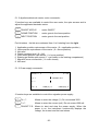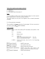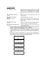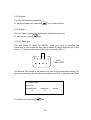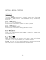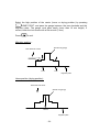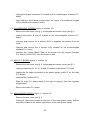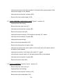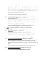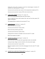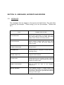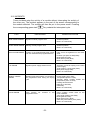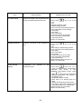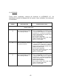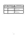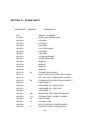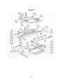
1
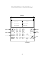
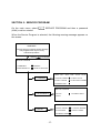
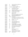
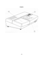
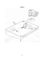
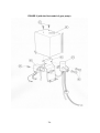
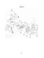
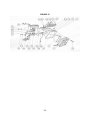
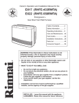
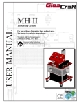
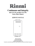
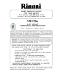
HYDRASYS LC TECHNICAL MANUAL HYDRASYS Version 1.0 Le 9 Novembre 1993 June 99 SUMMARY SECTION 1 : WARNING ...................................................................................... 1 SECTION 2 : INTRODUCTION ............................................................................ 4 SECTION 3 : TECHNICAL SPECIFICATIONS .................................................... 6 SECTION 4 : GENERAL DESCRIPTION............................................................. 8 SECTION 5 : SERVICE PROGRAM .................................................................... 14 SECTION 6 : SPECIAL FUNCTIONS .................................................................. 25 SECTION 7 : MECHANICAL ADJUSTMENTS .................................................... 27 SECTION 8 : DISMANTLING ............................................................................... 32 SECTION 9 : MAINTENANCE.............................................................................. 42 SECTION 10 : MESSAGES, INCIDENTS AND ERRORS ..................................... 44 SECTION 11 : SPARE PARTS .............................................................................. 52 SECTION 12 : FIGURES........................................................................................ 55 SECTION 13 : SCHEMATICS ................................................................................ 71 SECTION 1 : WARNING -1- SECTION 1 : WARNING AND SAFETY NOTES Follow all warnings and instructions marked on or supplied with the instrument. This service manual includes all information and warnings necessary for reliable and safe operation and maintenance. If the instrument is used in any other way than that specified by the manufacturer, operator’s safety may be compromised. The instrument has been designed to be used indoors. It can temporarily be subjected to temperatures up to + 50°C and down to -10°C (e.g., during transportation and storage) without any adverse effects on its safe use. Do not use the instrument near water or in wet locations. Do not place the instrument on an unstable cart, stand or table. Otherwise personal injury or damage to the instrument might occur. This instrument should be operated from the type of power source indicated on the instrument’s label and in this instruction manual. Before switching the instrument on, check that the voltage setting corresponds to the main power source. If you are unsure of the type of power available, consult your local power company. The instrument is equipped with a 3-wire grounding-type plug. The plug should only be connected to a grounded power outlet. Never use a ground adapter plug to connect the instrument to a socket lacking a ground connection terminal. Never interrupt ground leads or disconnect the ground terminal inside or outside the instrument. Use only fuses with appropriate rating value and of specified type. Make sure that the total amperage of all appliances plugged into the power outlet does not exceed the outlet protection. If an extension cord is used with this instrument, ensure that the total instrument amperage rating does not exceed the extension cord power rating. Disconnect the instrument from any power source before opening for testing, cleaning, adjustments, servicing or maintenance. Do not remove any covers when the instrument is connected to the main power source as this may expose dangerous live terminals. Never defeat interlock switches. They are provided to prevent access to unsafe areas. -2- Any adjustment, maintenance and servicing of an uncovered instrument without disconnecting it from power outlet must only be made by qualified and trained personnel, aware of the risks involved. -3- If it is believed that the instrument has been damaged and is unsafe, avoid using it and contact Sebia’s authorized representative. Manufacturer's Responsibility Sebia or Sebia’s authorized representative are responsible only for defects in material and services if : • Adjustments, alterations or servicing have been made by authorized personnel. • Electricity supply is in accordance with instrument specifications. • Instrument is used according to instructions. The manufacturer is not responsible for damage from misuse, abuse, accident and disasters, improper return shipping, or adjustments, alterations and servicing done by unauthorized personnel. The characteristics of HYDRASYS LC are described in this manual. SEBIA has the right to modify them without prior notice. -4- SECTION 2 : INTRODUCTION -5- SECTION 2 : INTRODUCTION This totally new system has opened the way to automation of electrophoresis techniques on the Hydragel agarose gels. HYDRASYS LC is a multiparameter semiautomated instrument which performs any agarose gel electrophoresis that is available in the manual Hydragel series of tests (e.g., Serum Proteins, Immunofixation, Lipoprotein + Lp (a), Hemoglobins alkaline and acid, Hemoglobin A1c, Chol-HDL,...). The automated electrophoresis steps are performed in sequence : sample application, migration, incubation, staining, destaining and drying. The manual steps include handling the samples and gels, and setting up the instrument for operation. Sample application is performed in a particularly ingenious and original way. The excellent quality of the applications allows the protein fractions to resolve into sharp and distinct bands. Migration parameters are regulated in constant current, constant voltage, constant power or volts x hour. Staining, destaining and drying steps are performed in a leak-proof compartment with a capacity of up to four different reagents. The HYDRASYS LC control panel is connected to an L.C.D. screen which can display menus, the working stages of each module and the progress of the ongoing procedural step. In addition, it displays messages, incidents and errors. HYDRASYS LC should be used only with the specifically designed HYDRAGEL kits, gels and reagents manufactured and tested by SEBIA. -6- SECTION 3 : TECHNICAL SPECIFICATIONS -7- SECTION 3 : TECHNICAL SPECIFICATIONS SAMPLE APPLICATION - Applicator : 7, 15 or 30 deposits Disposable microporous applicators Direct loading of 10 µL of biological fluid Automatic application controlled by the program MIGRATION - Capacity for 40 migration programs Constant voltage, current, power or volts x hour Voltage : 3.5 to 350 V Current : 3.5 to 200 mA Power : 0 to 30 W Temperature controlled by Peltier effect Drying assisted by additional heating element (90 W) STAINING, DESTAINING, DRYING - Capacity for 40 staining programs Teflon® coated molded aluminum compartment with 3 level detectors Entry/exit of liquids controlled by a 6 or 10-way valve Liquids circulate through a self-priming pump Drying by convection heater (600 W) with laminar air flow GENERAL SPECIFICATIONS - Keypad with 20 keys + shift L.C.D., 4 lines of 40 characters Safety lid-locks on the migration and staining modules Test and control program Power : 1000 VA Voltage : 115/230 V ± 10 % (factory selected) - 50/60 Hz Fuses : 230 V / 2 x 6.3 A (slow blow) 115 V / 2 x 10 A (slow blow) Dimensions : L 69 cm x W 52 cm x H 25 cm L 27.2 in x W 20.5 in x H 9.8 in Weight : 30 kg / 66 LB -8- SECTION 4 : GENERAL DESCRIPTION -9- SECTION 4 : GENERAL DESCRIPTION 4.1 EXTERNAL HARDWARE DESCRIPTION It consists of : - on the front panel (see figure 1 - section 4) : • a migration module (1) • a keypad with 20 keys + SHIFT (5) • a L.C.D. with 4 lines of 40 characters (2) • a staining / destaining / drying module (4) - on the right panel (see figure 1 - section 4) : • a 6 or 10-way valve (6) - on the rear panel (see figure 2 - section 4) : • an ON/OFF switch (3) • an A.C. power source inlet with fuses compartment (1) (2) • a waste overflow sensor inlet (4) • a 9 pin connector (AUX) allowing to download a new software in Flash EPROM through a serial link (5) with the help of a lap top computer or HYRYS densitometer. 4.2 INTERNAL HARDWARE DESCRIPTION (see figures 1 to 13 section 10) It consists of : - on the left, migration cover open : • a migration plate coated by a Teflon film • 2 electrodes (anode on the left and cathode on the right) • a motorised cam used to move the applicator / electrode carriers • a migration chamber fan (M7) • a migration cover microswitch (M3) - 10 - • a safety electromagnet to lock the migration cover (M2) - 11 - - in the middle, rear cover and screen / keypad cover removed : • a Main P.C. board (G11) -on the right, rear cover and screen / keypad cover removed : • a Teflon coated molded aluminium staining tank (C1) • 3 level probes (C3) • an electromagnet to lock the gel holder (C2) • a staining dryer P.C. board (C20) • a heating element (C13) • a fan (C7) with an airflow convector (C4) and (C5) • a pinch valve (B4) • a gear pump (G12) • an 6 or 10-way valve (G7) with a valve P.C. board (V5) - at the back, rear cover removed : • a power supply module (G10) 4.3 KEYPAD DESCRIPTION (see figure 3 - section 4) : - 12 - THE INSTRUMENT’S FRONT PANEL (Fig. 1) - 13 - THE INSTRUMENT’S REAR PANEL (Fig. 2) - 14 - THE INSTRUMENT’S KEYPAD AND SCREEN (Fig. 3) LCD SCREEN MIGRATION LED PROTEIN 15/30 STAINING LED PROTEIN 20° C 1 SELECT MIGRATION 3 SELECT STAINING 2 SERVICE PROGRAM 4 REAGENT LINES START MIGRATION 7 8 9 START STAINING STOP MIGRATION 4 5 6 STOP STAINING GREY KEY 1 2 3 ENTER SHIFT CE 0 . CURSOR KEYS - 15 - SECTION 5 : SERVICE PROGRAM - 16 - SECTION 5 : SERVICE PROGRAM On the main menu, select (4644) must be entered. 2 SERVICE PROGRAM and then a password When the Service Program is selected, the following warning message appears on the screen : WARNING ! Incorrect use may produce serious damage This program must only be run by authorized operators. Press to continue SERVICE PROGRAM 1 COMMANDS 3 MEMORY 2 KEYPAD/DISPLAY 4 SELECT LANGUAGE TESTS : T1:27 1 - COMMANDS T2:28 T3:25 OP : 68 CP:145 1 PELTIER & DRYER 4 PUMP & VALVE 2 APPLIC. MOTOR 5 FAN & ELEC. MAGNET 3 POWER SUPPLY SERVICE PROGRAM 2 - KEYPAD/DISPLAY 1 KEYPAD 3 PC SERIAL PORT 2 DISPAY MEMORY CHECK 3 - MEMORY 1 RESET HISTORY 4 CHECK & VERSION 2 FLASH PROG. 5 REINIT. PARAM. 3 INTERNAL PARAM. - 17 - 5.1 COMMANDS : Test program used to control the different elements of the migration and staining modules. 1 - PELT. & DRYER : Peltier effect and dryer commands 2 - APPLIC. MOTOR : applicator/electrode commands 3 - POWER SUPPLY : migration power supply commands 4 - PUMP & VALVE : pump and valve commands 5 - FAN & ELEC. MAGNET : fan and electromagnet commands carrier motor : exit of tests Note : When you exit by pressing , the instrument is initialized. If the pump and the valve have been used, the staining chamber is automatically drained to the waste container. Information displayed during the tests : T1 T2 T3 CP : : : : migration plate temperature (top surface of the Peltier modules) radiator temperature (bottom surface of the Peltier modules) staining dryer temperature analog input of the precise channel used to determine the temperature slope of the migration plate (value from 110 to 180) OP : offset of the precise channel (value from 45 to 65) 5.1.1 Peltier and dryer commands : TESTS : T1:27 T2:27 T3:27 OP:58 CP:153 1 ON/OFF MI. DRYER 3 ON/OFF ST. DRYER 2 ON/OFF PELTIER 4 SET UP PARAM. MI DRY : 0 ST DRY : 0 - 18 - PELTIER : 0 1 ON/OFF MI. DRYER : ON/OFF Migration Plate Dryer 2 ON/OFF PELTIER 3 ON/OFF ST. DRYER : ON/OFF Staining Dryer 4 SET UP PARAM. Working conditions : : ON/OFF Peltier Effect : Allows to set up the working conditions for testing the Peltier effect and the 2 dryers 4 migration dryer power (MI DRY) : power applied to the heating element (from 0 to 90 watts) MIGRAT. DRYER POWER ? BATH DRYER POWER ? staining dryer power (ST DRY) : power percentage (conduction time of the triac) applied to the heating element. For safety reasons, do not exceed 80 % PELTIER VOLTAGE ? Peltier voltage (PELTIER) : voltage applied to the Peltier modules (from 0 to 30 volts) MODE (0=COOLING) ? functioning mode of the Peltier effect (0 = cooling / 1 = heating). Note : By default, the 3 parameters are programmed to 10 and the cooling mode is selected. The "-" sign for the Peltier effect indicates cooling, the "+" sign indicates heating. WARNING : Peltier effect and dryer commands are 3 ON/OFF commands. This means that no regulation is effective, they are under control and responsability of the operator. Never exceed 80°C for T1, T2 and T3 temperatures to prevent any damage. - 19 - 5.1.2 Applicator/electrode carrier motor commands : 3 function keys are available to control the cam motor, the opto sensors and to adjust the applicator/electrode carrier. 1 ON/OFF APPLIC. : motor ON/OFF 2 HOME POSITION : motor goes to the home position 3 NEXT POSITION : motor goes to the next position Port bit status : the bits are numbered from 1 to 8 starting from the right 1 2 3 4 5 6 7 8 Application position opto sensor of the carrier (0 = application position) Home position opto sensor of the carrier (0 = home position) Not used Waste container level (0 = full) Valve home position opto sensor (1 = home position) Staining gel holder opto sensor (1 = gel holder in the staining compartment) Migration cover microswitch (1 = cover closed) Not used 5.1.3 Power supply commands : TESTS : V : 0 I:0 1U:? R : 0.00 3 ON/OFF P.S. 2I:? P.S. : 0 CMD (V) : 0 CMD (mA) : 0 3 function keys are available to control the migration power supply : 1 U=? Allows to enter the voltage (V). Do not exceed 350V 2 I=? Allows to enter the current (mA). Do not exceed 200 mA 3 ON/OFF P.S. Allows to start and stop the power supply. When the power is on, the instrument continuously displays the voltage, the current and the load values. - 20 - Values when migration power supply is selected : U = Value in V I = Value in mA R = Calculated value of the load in KΩ Notes : It is not possible to modify U and I when the power supply is on (first, stop the power supply and then, modify the working conditions). The power supply can only work if the migration cover is closed (microswitch activated). 5.1.4 Pump and valve commands : The accessible functions are spread on 2 screen pages. Go from one screen to 3 the other by pressing NEXT SCREEN FIRST SCREEN : First line : Values of the level probes (NTC thermistors) and position of the valve • LL : Low Level • ML : Medium Level • HL : High Level values of level probes without liquid : 70 ± 10 values of level probes with liquid : 150 ± 20 • LINE N : Position of the valve : from 1 to 6 or 1 to 10 according to the valve 1 VALVE ON/OFF : ON/OFF valve motor 2 NEXT POSITION : next position of the valve 3 NEXT SCREEN : allows to select the 2nd screen 4 ON/OFF ASPIRATION : ON/OFF pump filling under control of the operator to prevent any overflow of the tank 5 ON/OFF DRAINING : ON/OFF pump draining - 21 - 6 PUMP SET UP : allows to set up the pump speed (value from 1 to 4) to drain or fill the tank - 22 - SECOND SCREEN : 1 LINE & LEVEL : allows to select the line number and the tank filling level (1 = intermediate level, 2 = high level). Once the 2 parameters are validated, the valve goes automatically to the chosen line. 2 HOME POSITION : allows to select the home position of the 6 or 10-way valve 3 NEXT SCREEN : allows to select the 1st screen 4 FILL TANK : allows to fill the tank up to the defined level. During filling, pressing the key will stop the pump motor 5 WASTE TANK : allows to drain the tank. During draining, pressing the key will stop the pump motor. 6 PUMP CALIBRATION * : allows to calibrate only the first model of gear pump (SEIM model). This procedure must be performed after replacing the pump, the main P.C. board or downloading of a new software. It allows to calibrate automatically the maximum required pump current of the different cycles of the pump (aspiration, draining, agitation). Calibration parameters are stored in Internal Parameters (parameters 45 to 49). Pump motor current control allows to stop the pump immediately to avoid disconnection of tubing in case of high pressure (error 60 during filling of the tank or error 61 during draining of the tank). VALVE POSITIONNING IN PROGRESS CONNECT DESTAINING CONTAINER TO LINE 5 OF THE VALVE AND PRESS RETURN Please wait : Filling in progress Please wait : Measurement in progress Draining ... End of test - 23 - (*) The new magnetic drive gear pump (MICROPUMP model) does not need to be calibrated. When using this pump, the internal parameter setting should be the following (see § 5.3.3) : P9=1 , P45=200 , P46=200 , P47=200 , P48=200 , P49=200. 5.1.5 Fan and electromagnet commands CE : 0 MF : 0 PF : 0 TE : 0 SF : 0 PV : 0 1 COVER ELEC. MAGNET 4 TANK ELEC. MAGNET 2 MIGRATION FAN 5 STAINING FAN 3 PELTIER FAN 6 PINCH VALVE Six function keys are available to control fans, electromagnets and pinch valve. 1 COVER ELEC. MAGNET : ON/OFF migration cover electromagnet 2 MIGRATION FAN : ON/OFF migration fan 3 PELTIER FAN : ON/OFF modules 4 TANK ELEC. MAGNET : ON/OFF tank electromagnet 5 STAINING FAN : ON/OFF staining dryer fan 6 PINCH VALVE : ON/OFF pinch valve of the fluidic radiator fan of the Peltier Status of each element is displayed on the first line of the the screen : 1 = ON, 0 = OFF CE = migration cover electromagnet MF = migration fan PF = radiator fan of the Peltier modules TE = tank electromagnet SF = staining dryer fan PV = pinch valve 5.2 KEYPAD/DISPLAY : - 24 - SERVICE PROGRAM 1 KEYPAD 3 PC SERIAL PORT 2 DISPLAY - 25 - 5.2.1 Keypad : This test indicates the pressed key. To exit the keypad test, press the key for few seconds. 5.2.2 Display : This test starts a graphic test followed by an alphanumeric test. To exit the test, press key. 5.2.3 PC Serial port .: This test allows to check the RS232C serial port used to download the instrument. It can be started after having placed a jumper between pin 2 (RX) and pin 3 (TX) as shown below on the 9 pin connector (AUX 1). 1 5 AUX 1 REAR VIEW 9 6 The decimal ASCII code of the pressed key sent to the transmission output (TX) and received through the loop by the reception input (RX) is displayed as follows : PC SERIAL PORT Press a key TRANSMITTED : 49 To exit the test, press the RECEIVED : 1 49 key. - 26 - ERROR : 1 Note : This test allows to check the ACIA 6850 (IC 24) and the 2 input/output adaptors 1488 (IC 25) and 1489 (IC 26) on the mother P.C. board. 5.3 MEMORY : MEMORY CHECK 1 RESET HISTORY 4 CHECK & VERSION 2 FLASH PROG. 5 REINIT. PARAM. 3 INTERNAL PARAM. Test program used to reset the history, to download a new software, to check the memory and modify or reinitialize the internal parameters. Note : - Memory consists of a Flash MEMORY and a RAM. - The Flash MEMORY is used to store the instrument software and the different migration and staining programs. The Flash MEMORY is also used to store the internal parameters, the heater temperature regulation parameters, the latest values of the 3 level probes and the staining cycle step in progress in case of power failure. 5.3.1 RESET HISTORY : This test allows to reset information stored in the Flash MEMORY such as the latest migration and staining programs selected, the heater regulation parameters, the latest values of the 3 level probes and the staining cycle step in progress in case of power failure. When this test has been performed, the instrument runs automatically a draining cycle of the staining tank. - 27 - 5.3.2 FLASH PROG.: This test allows to download a new software version through the serial link with a PC or HYRYS densitometer. When this test is selected and validated by pressing 1 CONTINUE, the instrument emits an intermittent beep and displays "SHUTTING DOWN" indicating that it is waiting for a new software downloading. Note : For more details to download a new software version, refer to the FLASH INSTRUCTION MANUAL. If the test is selected by error, turn the instrument off to start from the beginning. 5.3.3 INTERNAL PARAMETERS : Do not modify except the next parameters according to the instrument configuration : P9* = 0 with the first model of gear pump (SEIM model) = 1 with the new magnetic drive gear pump (MICROPUMP model) P44* = 6 with the 6-way valve = 10 with the 10-way valve P45 to P49 = pump calibration parameters with the first model of gear pump (SEIM model), parameters set to 200 with the new magnetic drive gear pump (MICROPUMP model). (* : as of software release 6.XX.XX). 5.3.4 MEMORY CHECKSUM AND VERSION : This test allows to know the Flash memory checksum and the software version. 5.3.5 REINIT. PARAMETERS : 1 This test allows by pressing CONTINUE to reinitialize the internal parameters. Then refer to § 5.3.3 to set the internal parameters according to the instrument configuration. 5.4 SELECT LANGUAGE : This menu allows to select the user's language : French, English, German, Spanish, Portuguese or Italian. - 28 - SECTION 6 : SPECIAL FUNCTIONS - 29 - SECTION 6 : SPECIAL FUNCTIONS HIDDEN KEYS : The special key is necessary to activate the functions below. After having pressed the shortly after. key, one must press the additional two keys simultaneously + SHIFT MIGRATION : Allows to shorten the time of each migration cycle phase in process. + SHIFT STAINING : Allows to shorten the time of each staining cycle phase in process. + SHIFT C E : Allows to give access directly to the test program in case of error message, then enter password : 4644 + SHIFT : Resets the history and the instrument which starts up again and indicates "INCORRECT STOP" and thus drains the tank to the waste container. Warning : do not use this function when the tank is full of staining solution because stain will be drained to the waste instead of to the staining container. - 30 - SECTION 7 : MECHANICAL ADJUSTMENTS - 31 - SECTION 7 : MECHANICAL ADJUSTMENTS 7.1 APPLICATOR / ELECTRODE CARRIER : To perform the adjustment proceed as follows : - turn the instrument on and let it finish its initialization - select 2 Service Program and enter the password 4644, press 1 COMMANDS and 2 APPLIC. MOTOR - open the migration chamber cover and insert the side-lateral carrier into the lateral slots. The axis guides must slide into the slots without difficulty, right up to the end. If not, pivot one of the axis guide according to the other. - make the carrier rise and fall with the 1 ON/OFF APPLIC. command. - observe the movement of the carrier : it should be smooth and regular. 7.1.1 APPLICATOR CARRIER ADJUSTMENT Insert 2 applicators in position 1 and 13. Put the carrier in the lowest position (application position) by pressing NEXT POSIT. 3 Adjust the screw (front screw) on the applicator arm underneath the cam so that the carrier is horizontal (parallel to the migration plate) and that the 2 applicators are distant of 1.5 to 2 mm from the carrier on both sides as shown on the next page. - 32 - APPLICATOR APPLICATOR CARRIER APPLICATOR CARRIER 1.5 TO 2 MM MIGRATION PLATE APPLICATOR TEETH MUST TOUCH Once the adjustment is made, press 3 NEXT POSIT., make a complete cycle and check the 1.5 to 2 mm distance. If correct, block the lock screw with a flat wrench (5 mm). NEXT Go to the intermediate position (migration position) by pressing 3 POSIT. and check that the applicator teeth are at least 4 mm above the migration plate. Take out the applicators. 7.1.2 ELECTRODE CARRIER ADJUSTMENT It consists of the rear electrode carrier (anode) adjustment. Select the intermediate position (migration position) by pressing POSIT. 3 NEXT Adjust the screw of the electrode carrier (rear screw) underneath the cam so that there is more than 7 mm and less than 8 mm between the migration plate and the electrode. The edge (7 mm thickness) of the special tool (gauge) must pass under the electrode up to the 8 mm thickness. Check the adjustment by making a complete cycle of the carrier. - 33 - Select the high position of the carrier (home or drying position) by pressing 2 HOME POSIT. and pass the gauge between the rear electrode and the migration plate. The gauge must pass easily (more than 16 mm height). If correct, block the lock screw with a flat wrench (5 mm). Press to exit. Migration position : Special tool (gauge) Rear electrode carrier 8 mm 7 mm Migration plate Home position (drying position) : Rear electrode carrier Special tool (gauge) 16 mm Migration plate - 34 - Notes : For both carriers, perform the adjustments without any gel on the migration plate. There is no adjusment for the front electrode carrier (cathode). Concerning the second adjustment (electrode carrier), the tolerance thickness of the sponges is 10 ± 2 mm. In migration position with less than 8 mm, the contact gel/sponge/electrode is perfect. In drying position, with more than 16 mm there is no contact between the gel and the sponge. - 35 - SECTION 8 : DISMANTLING - 36 - SECTION 8 : DISMANTLING This section describes the procedures to dismantle the instrument in order to check or to replace parts of the instrument. Proceed in the opposite way to reinstall the instrument. Refer to Section 12 for the drawings. CAUTION : To avoid electrical shock, make sure the instrument is disconnected from the A.C. power source before being opened. Required tools : - slotted head screw driver : 4 mm - Allen wrenchs : 1.5 mm - 2 mm - 2.5 mm - 3 mm - Torx wrench : Torx 10 - Torque wrench : set to 56 cNm - pliers - cutting pliers - soldering iron - dust brush. 8.1 REAR COVER (figure 3 - section 12): Unscrew and remove the 3 screws (G22), pull to the back and remove the rear cover (G3). 8.2 KEYPAD AND SCREEN COVER (figures 3, 8 and 9 - section 12) - Remove the rear cover (see § 1) - Unscrew and remove the 2 front screws (G16) - Unscrew and remove the 2 rear screws used to fix the cover on the staining tank - Lift slightly the cover (A1), unplug the connector J10 located on the main P.C. board. 8.3 KEYPAD (figure 8 - section 12) - Remove the rear cover (see § 1), the keypad and screen cover (see § 2) - 37 - - Unplug the keypad connector J2 located on the screen/keypad interface P.C. board - Insert slightly a small blade at the bottom left corner of the adhesive keypad (G5) to unstick and remove it totally. 8.4 FLUORESCENT SCREEN (figure 8 - section 12) - Remove the rear cover (see § 1), the keypad and screen cover (see § 2) - Unplug connectors J2 and J3 located on the screen/keypad interface P.C. board - Unscrew and remove the 4 screws (A19) to separate the module from the cover. - Unscrew and remove the 4 screws (A10) situated on the screen/keypad interface P.C. board. - Unsolder the 2 wires (Black, Red) of the screen from the keypad interface P.C. board (+VLCD,0V5), then the screen is free. 8.5 MAIN P.C. BOARD (figure 3 - section 12) - Remove the rear cover (see § 1), the keypad and screen cover (see § 2) - Unplug connectors J2, J3, J5, J8 and J9 located on the main P.C. board - Unplug the flat cable connected to the power supply (cable J7 on the main P.C. board) - Unscrew the 2 screws (G17) - Slide the main P.C. board slowly to the right to unplug it from the migration compartment - Remove the main P.C. board 8.6 MAIN POWER SUPPLY (figure 3 - section 12) - Remove the rear cover (see § 1) - Unplug all connectors located on the front of the main power supply, and the connector located at the bottom right corner of the main power supply - 38 - - Unscrew and remove the screw used to fix the earth wire (green/yellow) of the main power supply on the chassis - Unscrew and remove the 5 screws (G18) - Remove the main power supply (G10) 8.7 PUMP ASSEMBLY AND PINCH VALVE (figure 9 - section 12) - Unplug all the valve tubing - Remove the rear cover (see § 1) - Unscrew and remove the 2 screws (B7) - Remove the pump cover (B1) - Unplug the pump connector (J5) located on the main P.C. board - Unscrew and remove the 2 screws (B6) - Unplug both pump tubings - Remove the pump assembly (G12) - Remove the tubing from the pinch valve - Unscrew and remove the screw used to fix the earth wire of the pinch valve at the bottom of the chassis - Unplug the connector J2 located on the valve P.C. board - Unscrew the 2 screws used to fix the pump holder (B2) on the chassis - Unscrew and remove the 2 screws (B5) - Remove the pinch valve (B4). 8.8 VALVE ASSEMBLY (figures 3 and 9 - section 12) - Remove the rear cover (see § 1) - Unplug all the valve tubings - Unscrew and remove the 4 screws (V15) - Remove the valve metal plate (V14) - 39 - - Unplug connector J2 located on valve motor P.C. board and the connector J2 located on the staining dryer P.C. board - Unscrew and remove the 4 screws (G21) - Remove the mechanical part of the valve. 8.9 VALVE MOTOR AND VALVE P.C. BOARD (figure 10 - section 12) - Remove the rear cover (see §1) - Remove the valve assembly (see §8) - Unscrew and remove the 2 screws (V6) - Untight the 2 screws (V21) - Unscrew and remove the 2 screws (V8) - Slide the motor to the right and remove it with the P.C. board - Unsolder the 4 wires of the motor from the valve P.C. board (P1, P2, P3 and P4), then the motor and the valve P.C. board are free - The screws (V21) must be well tightened on the motor shaft flat to prevent any play between the motor and the valve cam. 8.10 STAINING/DESTAINING/HEATER ASSEMBLY (see figures 3, 9 and 12 section 12) - Remove the rear cover (see §1), the keypad and screen cover (see §2) - Unplug all valve tubings - Unscrew and remove the 2 screws (B7) - Remove pump cover (B1) - Unplug the pump tubing connected to the tank bottom fitting - Unplug the top valve tubing connected to the tank top fitting - Unplug the flat connector J8 located on the main P.C. board - Unplug the connector J2 located on the staining dryer P.C. board - 40 - - Untight the 2 screws of J6 and unplug the 2 wires (black wire connected to position 1, white wire connected to position 3 of J6) - Unscrew and remove the screw (C24) used to fix the earth wire (C22) (green/ yellow) and the bottom left screw (C25) used to fix the other earth wire - Unscrew and remove the 4 screws (G19) - Remove the staining/destaining/dryer assembly 8.11 HEATING ELEMENTS (see figure 12 - section 12) - Remove the rear cover (see §1), the keypad and screen cover (see §2) - Untight the 2 screws (position 1 and 3) of J7 (located on the staining dryer P.C. board) and unplug the 2 wires - Unscrew and remove the 2 screws (C12) - Pull up the heating elements (C13) with the protection cover (C14) Note : The assembly consists of 1 resistor and 1 thermal switch. 8.12 DRYER FAN (see figure 12 - section 12) - Remove the staining/destaining/dryer assembly (see §10) - Unplug the fan connector J3 located on the staining dryer P.C. board - Unscrew and remove the 4 screws (C8) then the fan (C7) is free. 8.13 GEL HOLDER ELECTROMAGNET (see figure 12 - section 12) - Remove the rear cover (see §1), the keypad and screen cover (see §2) - Unplug the electromagnet connector J5 located on the staining dryer P.C. board - Unscrew with pliers the electromagnet (C2) from the tank and remove it. 8.14 STAINING/DESTAINING TANK (see figure 12 - section 12) - Remove the staining/destaining/dryer assembly (see §10) - 41 - - Unplug the level probe connector J4 and the electromagnet connector J5 located on the staining dryer P.C. board - Unscrew and remove the screw used to fix the temperature transducer (C11) - Unscrew and remove the 4 screws (C25), then the tank is free. 8.15 TANK LEVEL PROBE (see figure 12 - section 12) - Remove the staining/destaining tank (see §10 and §14) - Insert a blade flat screw driver between the tank and the level probe (C3) edge to disengage it - The leakproofness is made by the level probe "O" ring. 8.16 RADIATOR FAN (see figure 4 - section 12) - Remove the rear cover (see §1) - Unscrew and remove the 4 screws (M13) - Remove the fan protection grid (M12) - Unscrew and remove the 4 screws (M14) - Unplug the fan connector J2 located on the cam motor P.C. board - Remove the radiator fan (M11). 8.17 MIGRATION MODULE (see figure 3 - section 12) - Remove the rear cover (see §1), the keypad and screen cover (see §2) - Unplug the high voltage connector located on the main power supply - Unscrew and remove the 6 screws (G19) - Slide the migration module to the left to disengage it from the main P.C. board (G11) - Lift the migration module (G4) up to remove it. 8.18 MIGRATION COVER ELECTROMAGNET (see figure 5 - section 12) - 42 - - Remove the rear cover (see §1), the keypad and screen cover (see §2) - Unscrew and remove the 2 screws (M8) - Unsolder the 2 wires and remove the electromagnet (M2) with its holder - 43 - 8.19 CAM MOTOR AND CAM MOTOR P.C. BOARD (see figures 4 and 5- section 12) - Remove the rear cover (see §1) - Unscrew and remove the 4 screws (M13) - Remove the fan protection grid (M12) - Unscrew and remove the 4 fan screws (M14) to slide it to the back - Unplug the connectors J1, J2 and J3 located on the cam motor P.C. board. - Open the migration cover (M1) - Unscrew and remove the 4 screws (M9) - Remove the cam motor with the P.C. board - Unsolder the 4 wires of the motor from the P.C. board (P1, P2, P3 and P4) - Unscrew the cam screw - Remove the cam - Unscrew and remove the 2 screws (M15), then the motor and the cam P.C. board are free. - The cam screw must be well tightened on the motor shaft flat to prevent any play between the motor and the cam. 8.20 PELTIER MODULES (see figure 5 - section 12) - Remove the migration module (see § 17) and put it upside down - Unscrew and remove the 8 screws (M16) - Remove the radiator (M10a) (be careful, the temperature transducer T2 is fixed on it) - Remove the radiator (M10b) - Then you have access to the 2 Peltier modules (M5). Note : The Peltier modules are connected in series (be careful of their polarity). - 44 - WARNINGS TO REASSEMBLE THE PELTIER MODULES (M5) : - Apply a regular layer of thermal grease (silicon compound) on both sides - Center the 2 Peltier modules with the migration plate (respect the position given by the black and red wires) - Install the 2 radiators (M10a and M10b) - Insert the 8 radiator screws (M16) with the washers and tight them slowly, alternating the screws with a torque screw driver set to 56 cNm (centi Newton meter) - Check that the both Peltier modules remain centered on the migration plate and note that thermal grease escapes aroung module edges - Tighten the 8 screws until the limit given by the torque screwdriver. 8.21 MIGRATION FAN (see figure 5 - section 12) - Remove the migration module (see § 17) and put it upside down - Unplug the fan connector J7 located on the cam motor P.C. board - Remove the radiator (M10a) (see § 20) - Unscrew the 2 screws (M17) - Remove the migration fan (M7) with its holder 8.22 THERMAL SWITCH AND TEMPERATURE PROBES T1 AND T2 (see figure 5 - section 12) - Remove the migration module (see § 17) and put it upside down - Remove the 2 radiators (M10a) and (M10b) (see §20) - Unsolder the 2 wires from the thermal switch (M22) - Unscrew and remove the screws of the thermal switch, then it is free - Unsolder the 2 wires from the temperature probe T1 - Unscrew and remove the screw of the probe, then it is free - 45 - - For transducer T2 which is fixed on radiator (M10a), the procedure is the same. - 46 - WARNINGS : - The hole where is inserted the temperature probe must be full of thermal grease (silicon compound). - Use epoxy glue on the temperature probe P.C. board to prevent any short circuit with water condensation between the legs of the transducer. 8.23 MIGRATION HEATING ASSEMBLY (see figure 5 - section 12) - Remove the migration module (see § 17) - Insert slightly a small blade between one of the corners of the adhesive migration film (M25) and the migration surface to unstick and remove it completely - Put the migration module upside down - Remove the Peltier modules (see § 20) - Unscrew and remove the 8 screws (M18) - Remove fixation parts (M19 and M20) - Remove the temperature probe T1 (see §22) - Unscrew and remove the 2 screws (M24) used to fix the 2 earth wires (green and yellow) - Unsolder the 2 wires of the heating element (blue and Grey) from the connector of the migration module, then the migration heating assembly is free. - 47 - SECTION 9 : MAINTENANCE - 48 - SECTION 9 : MAINTENANCE 9.1 DAILY : After each migration gently wipe the electrodes lengthwise and the migration plate with a wet tissue paper. 9.2 WEEKLY : 1/ To avoid accumulation of salt on the electrodes, soak the migration carrier horizontally overnight in a bath filled to 5 mm height of distilled water. Wipe with a dry tissue before putting it back in place. 2/ To clean the staining tank, proceed as follows : - reconstitute the washing solution as indicated in the instruction leaflet of the kit : HYDRASYS WASH SOLUTION ref. 4541. - be sure that there is enough destaining solution (300 ml) - from the main menu, press menu 3 to have access to the staining program - select TANK CLEANING program - press START key (green arrow on the right of the keypad) The cleaning program consists of 3 steps : • one bath of washing solution connected to the line 6 of the valve (washing solution 1). It lasts 5 min. with intermittent circulation of the solution. When the cycle is finished, the solution goes to the waste. • one bath of destaining solution connected to line 5 of the valve. It lasts 1 min. and 40 sec. with intermittent circulation of the solution. When the cycle is finished, the solution goes to the waste. • one drying step which lasts 8 min. After drying, the instrument emits a "beep" indicating that the cleaning program is finished and the gel holder is unlocked. 9.3 YEARLY : Replace the pinch-valve and valve tubings, lubricate the 4 "O" rings of the applicator/electrode carrier and check its adjustment (refer to section 7). - 49 - Maintenance kit : p/n 10043545 - 50 - SECTION 10 : MESSAGES, INCIDENTS AND ERRORS - 51 - SECTION 10 : MESSAGES, INCIDENTS AND ERRORS 10.1 MESSAGES : The messages that can appear on the screen are listed below. They ask either to stand by (for example : "Plate cooling") or to act (for example : "Waste tank full"). CORRECTIVE ACTION TITLE PLATE HEATING Wait for rise in temperature of migration plate. If too long, check relays K1 and K2, IC28, 30V power supply, Peltier modules and heating element PLATE COOLING Wait for cooling of migration plate. If too long, check relays K1 and K2, IC28, 30V power supply and Peltier modules ILLEGAL SELECTION Wrong selection IN OPERATION Message appears if a program is chosen while one is already running WASTE TANK FULL Empty the waste container CLOSE DOOR Message appears if the migration program is started with the door opened. Close the door then start the migration procedure again. OPEN / CLOSE DOOR Open or close compartment NO GEL HOLDER If the staining program is started without first introducing the gel holder, this message will appear on the screen. Introduce the gel holder then start the staining procedure again - 52 - the door of the migration 10.2 INCIDENTS These incidents stop the activity of a module without interrupting the activity of the other one. The incident appears in the part of the screen corresponding to the module affected. The module will then be put in the pause mode. Pressing the corresponding green start TITLE MIGR. MODE ERROR key restarts the interrupted cycle. EXPLANATION CORRECTIVE ACTION - Software problem - Main P.C. board faulty Migration module program error STAIN. MODE ERROR Staining module program error - Software problem - Main P.C. board faulty APPLICATOR ERROR Position of the applicator/electrode carrier - Cam screw not tightened on the motor shaft cam not reached in the programmed time - Position opto (MA1 or MA2) faulty - Motor/gear box faulty - Motor driver (IC38) faulty - Main P.C. board faulty P.S. ERROR Migration power supply serial link error MIGRAT. DRYER ERROR Migration plate temperature not reached in - Power supply (30V) faulty the programmed time during the drying - Temperature probe T1 faulty - Thermal switch located beside cycle temperature probe T1 faulty - Heating element broken - Relay K1 or K2 faulty - IC28 faulty - Main P.C. board faulty VALVE ERROR Valve position not programmed time reached - 53 - in - Serial link connector unplug on the main power supply - ACIA (IC22) or circuit (IC23) faulty - Main power supply faulty - Main P.C. board faulty the the - Valve coupling screws loose on the motor shaft flat - Valve origin position opto faulty - Motor/gear box faulty - Motor driver (IC41) faulty - Gate array Automate 2 (IC21) faulty - Main P.C. board faulty TITLE EXPLANATION CORRECTIVE ACTION FILLING ERROR Chamber not filled in the programmed time or high level detected before low level - Press start key to run a new cycle - Jam - Reagent container empty - Reagent tubing pinched - Pinch valve and valve tubings pinched - Valve metal plate screws not tight - Pump faulty - Valve faulty - Pinch valve faulty - Pump motor driver (IC31) faulty - Pinch valve driver (IC28) faulty - Level probes faulty - Main P.C. board faulty DRAINING ERROR Chamber not drained in the programmed - Press start key to run a new time cycle - Jam - Stain tubing or waste tubing pinched - Pinch valve and valve tubings pinched - Valve faulty - Pinch valve faulty - Pump faulty - Pump motor driver (IC31) faulty - Pinch valve driver (IC28) faulty - Level probes faulty - Make a Reset History (see § 5.3.1) - Main P.C. board faulty STAIN. DRYER ERROR Temperature not programmed time reached in the - Press start key to run 1 or 2 cycles. If incident remains, select RESET HISTORY (see section 7) from MEMORY and TESTS menus. Press 1 - - 54 - CONT. to reset the temperature regulation parameters and execute a new staining cycle Temperature probe T3 faulty Check fuse F3 on staining dryer P.C. board Heating element/thermal switch faulty Triac (Q2) or opto-isolator (MA2) located on the staining dryer P.C. board faulty Staining dryer P.C. board faulty Main P.C. board faulty 10.3 ERRORS These errors completely interrupt all functions of HYDRASYS LC. An identification number is displayed on the screen. Upon validation, the instrument is reinitialized. ERROR EXPLANATION CORRECTIVE ACTION LEVEL DETECTOR 40 Low level detection problem - Select COMMANDS from TESTS menu : on the screen next to LL, it must be in the staining chamber indicated 70 ± 10 when the chamber is empty, 150 ±20 when the chamber is full - Low level probe faulty - A/D converter (IC8) faulty - Amp (IC34), current mirror (Q6), diode (D36) or transitor (Q5) faulty - Main P.C. board faulty 41 Mid level detection problem in - Select COMMANDS from TESTS menu : on the screen next to ML, it must be the staining chamber indicated 70 ± 10 when the chamber is empty, 150 ±20 when the chamber is full - Middle level probe faulty - A/D converter (IC8) faulty - Amp (IC34), current mirror (Q10), diode (D38) or transistor (Q9) faulty - Main P.C. board faulty 42 High level detection problem - Select COMMANDS from TESTS menu : on the screen next to HL, it must be in the staining chamber indicated 70 ± 10 when the chamber is empty, 150 ±20 when the chamber is full - High level probe faulty - A/D converter (IC8) faulty - Amp (IC35), current mirror (Q8), diode (D37) or transistor (Q7) faulty - Main P.C. board faulty - 55 - ERROR CORRECTIVE ACTION EXPLANATION THERMAL REGULATION 50 Regulation problem with the - Select COMMANDS from TESTS menu : on the screen next to T1 is indicated migration plate temperature the migration plate temperature. The probe T1 (top side of the measured value is not within the defined Peltier modules) limits (5°C to 95°C) - Temperature probe T1 faulty - Amp (IC9) or A/D converter (IC8) faulty - Main P.C. board faulty 51 Regulation problem with the - Select COMMANDS from TESTS menu : on the screen next to T2 is indicated radiator temperature probe the radiator temperature of the Peltier T2 (bottom side of the Peltier modules. The measured value is not modules) within the defined limits (5°C to 95°C) - Temperature probe T2 faulty - Amp (IC9) or A/D converter (IC8) faulty - Main P.C. board faulty 52 Regulation problem with the - Select COMMANDS from TESTS menu : on the screen, next to T3 is indicated staining dryer module the dryer temperature. The measured temperature probe T3 value is not within the defined limits (5°C to 95°C). - Temperature probe T3 faulty - Amp (IC9) or A/D converter (IC8) faulty - Staining dryer P.C. board faulty - Main P.C. board faulty MOTOR CURRENT DETECTION 60 Gear pump motor current con-sumption too high during filling of the tank with the first model of pump (SEIM model) - 56 - - Pump jammed : dismantle the pump body to clean the 2 gears - Reagent tubings pinched - Pinch valve and valve tubings pinched - Pump faulty - Pinch valve or valve faulty - Incorrect pump current calibration (see section 5.1.4) - Pump motor driver (IC31) faulty - Pinch valve driver (IC28) faulty - Main P.C. board faulty ERROR EXPLANATION CORRECTIVE ACTION 61 Gear pump motor current con-sumption too high during draining of the tank with the first model of pump (SEIM model) - Pump jammed : dismantle the pump body to clean the 2 gears - Reagents and waste tubings pinched - Pinch valve and valve tubings pinched - Pump faulty - Pinch valve or valve faulty - Incorrect pump current calibration (see section 5.1.4) - Pump motor driver (IC31) faulty - Pinch valve driver (IC28) faulty - Main P.C. board faulty FAN REVOLUTION DETECTION 65 Migration chamber fan - Fan stopped : jam or mechanical problem problem (fan too slow or no - Fan faulty revolution pulses received) - Fan connector unplugged - Power supply (24V) faulty - Motor driver (IC 33) faulty - Fan controller (IC42) faulty - Gate array automate 1 (IC20) or gate array automate 2 (IC21) faulty - Main P.C. board faulty 66 Radiator fan problem (fan too - Fan stopped : jam or mechanical problem slow or no revolution pulses - Fan faulty received) - Fan connector unplugged Power supply (24V) faulty - Motor driver (IC 28) faulty - Fan controller (IC44) faulty - Gate array automate 1 (IC20) or gate array automate 2 (IC21) faulty - Main P.C. board faulty 67 Staining module problem (no - Fan stopped : jam or mechanical problem revolution pulses received) - Fan faulty - Fan connector unplugged Power supply (24V) faulty - Motor driver (IC 33) faulty - Fan controller (IC45) faulty - Gate array automate 1 (IC20) or gate array automate 2 (IC21) faulty - Main P.C. board faulty - 57 - ERROR CORRECTIVE ACTION EXPLANATION MISCELLANEOUS 72 Interruption problem (FIRQ) - Switch off the instrument for 40 s and restart - Main P.C. board faulty 99 Interruption problem (IRQ) - Switch off the instrument for 40 s and restart - Software problem - Main P.C. board faulty - 58 - SECTION 11 : SPARE PARTS - 59 - SECTION 11 : SPARE PARTS REFERENCE DRAWING DESIGNATION 1270 HUMIDITY CHAMBER 10037021 MASK POSITIONNING AXIS 10037022 2 IF MASK 10037023 4 IF MASK 10037024 2 BJ MASK 10037025 12 IF PENTA MASK 10037026 4 BJ MASK 10037027 CSF MASK 10037031 15 ENZYMES MASK 10037032 30 ENZYMES MASK 10037033 MASK R1 10037034 MASK R2 10037035 MASK R3 10037036 MASK R4 10037110 G6 STAINING GEL HOLDER 10037111 RIGHT AXIS FOR STAINING GEL HOLDER 10037112 LEFT AXIS FOR STAINING GEL HOLDER 10037120 G6 STAINING GEL HOLDER FOR HYDRAGEL 7 10037210 CONTAINER 5 L 10037220 CONTAINER 0.5 L (BLACK CAP) 10037221 CONTAINER 0.5 L (RED CAP) 10037250 CONTAINER 2 L 10037514 M23 MIGRATION TEMP. PROBE PC BOARD 10037563 C11 STAINING TEMP. PROBE PC BOARD 10037566 C3 LEVEL PROBE 10037567 C1 STAINING TANK 10037800 10037810 APPLICATOR/ELECTRODE CARRIER P1 REAR ELECTRODE CARRIER ASSY - 60 - 10037820 P2 FRONT ELECTRODE CARRIER ASSY 10043400 G10 POWER SUPPLY 10043511 10043513 CAM MOTOR P.C. BOARD M4+M6+M21 10043540 10043541 MIGRATION HEATING ASSY VALVE ASSY (6 LINES) V5 10043543 VALVE MOTOR P.C. BOARD VALVE ASSY (10 LINES) 10043545 V18 TUBING KIT FOR 6 AND 10-WAY VALVES 10043550A G12 MAGNETIC DRIVE GEAR PUMP 10043562 C20 STAINING DRYER P.C. BOARD 10043700 G11 MAIN P.C. BOARD 21015019 RELAY 24V - 5A 31001724 MIGRATION COMPARTMENT PLASTIC BODY 31001725 M1 MIGRATION COMPARTMENT COVER 31001781 M25 MIGRATION PROTECTIVE FILM 31001783 P16/P19 SPONGE'S PIN 31001808 LEFT HANDLE OF THE STAINING GEL HOLDER 31001809 RIGHT HANDLE OF THE STAINING GEL HOLDER 31001817 G5 GEL POSITIONING GUIDE 31002078 G5 KEYPAD 31002086 V12 6-WAY VALVE INLET 31002087 V13 6-WAY VALVE COMMON POINT 40000326 CONTAINER TUBING 3 X 6 (1M) 40000356 M5 PELTIER ELEMENT 42589005 C13 HEATING ELEMENT 230V (STAINING) 42589006 C13 HEATING ELEMENT 115V (STAINING) 45360015 M2 MIGRATION COVER ELECTROMAGNET 45360016 C2 GEL HOLDER ELECTROMAGNET 45360024 B4 PINCH VALVE 45400031 A6 DISPLAY 45640013 OPTO SENSOR OPB 87L55 45750006 TRIAC TIC 253D 49600071 TEMPERATURE PROBE AD593CN 50000022 M26/V7 CAM/VALVE MOTOR + GEAR BOX 51000010 M11 RADIATOR FAN - 61 - 51000011 M7 MIGRATION FAN 51000012 C7 STAINING DRYER FAN - 62 - SECTION 12 : FIGURES - 63 - FIGURE 1 - 64 - FIGURE 2 - 65 - FIGURE 3 (with the first model of gear pump) - 66 - FIGURE 3 (with the new magnetic drive gear pump) - 67 - - 68 - FIGURE 4 - 69 - FIGURE 5 - 70 - FIGURE 6 - 71 - FIGURE 7 - 72 - FIGURE 8 - 73 - FIGURE 9 (with the first model of gear pump) - 74 - FIGURE 9 (with the new magnetic drive gear pump) - 75 - FIGURE 10 - 76 - FIGURE 11 - 77 - FIGURE 12 - 78 - FIGURE 13 - 79 - SECTION 13 : SCHEMATICS - 80 - - 81 - - 82 - - 83 - - 84 - - 85 - - 86 - - 87 - - 88 - - 89 - - 90 - - 91 - - 92 - - 93 - - 94 - - 95 -