1
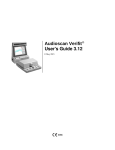
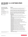
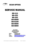
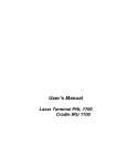
XPRT1
SINGLE COMPRESSOR CONTROLLER
INSTALLATION AND SERVICE MANUAL
1545 Industrial Drive
Missouri City, Texas 77489
(281) 499-5697
Rev. F
TABLE OF CONTENTS
SECTION A: GENERAL INFORMATION
System Features .................................................................................................................. A-1
Ordering Information (Part Numbers / Description).............................................................. A-1
SECTION B: SPECIFICATIONS
CPU-X1 Controller Specifications ........................................................................................ B-1
XIO1 Input / Output Relay Board Specifications .................................................................. B-1
LPTX2 / LPTX4 Low Pressure Transducers........................................................................ B-1
HPTX2 / HPTX4 High Pressure Transducers ..................................................................... B-1
TM-1 Temperature Sensor Specifications (Low Temp. Probe) ............................................ B-1
TM-2 Temperature Sensor Specifications (High-Temp. Probe)........................................... B-2
TM-2A Temperature Sensor Specifications (Demand Cooling Probe)................................. B-2
LPTX2 to LPTX4 Converter.................................................................................................. B-2
HPTX2 to HPTX4 Converter ................................................................................................ B-2
Contactor Filter Specifications.............................................................................................. B-2
CRX1 Relay Board Specifications........................................................................................ B-2
SECTION C: OPERATION
Display and Keypads............................................................................................................ C-1
Changing Settings................................................................................................................ C-1
Quick Keys........................................................................................................................... C-1
Display Contrast Adjustment................................................................................................ C-1
Status and Configuration Screens........................................................................................ C-1
CPU-X1 LED Status Indicators............................................................................................ C-1
XPRT1 Status Screens........................................................................................................ C-2
XPRT1 Configuration Screens............................................................................................. C-4
XIO1 Input/Output Board Operation ..................................................................................... C-6
Suction Pressure Control Logic............................................................................................ C-6
Temperature Control Logic................................................................................................... C-6
Condensing Pressure Control .............................................................................................. C-6
Defrost Logic........................................................................................................................ C-6
Oil Pressure Logic................................................................................................................ C-6
Demand Cooling Logic ......................................................................................................... C-6
Pump Down Logic (Liquid Line Solenoid)............................................................................. C-6
SECTION D: APPLICATION
Defrost Termination.............................................................................................................. D-1
Condensing Pressure Control .............................................................................................. D-1
SECTION E: INSTALLATION
Parts Needed ....................................................................................................................... E-1
Controller Mounting and Wiring............................................................................................ E-1
Pressure Transducer Installation ......................................................................................... E-2
Pressure Transducer Wiring................................................................................................ E-2
TM-1 and TM-2 Temperature Sensor Installation and Wiring ............................................. E-2
Averaging Four TM-1 Temp Sensors................................................................................... E-2
Control Relay Wiring ............................................................................................................ E-3
Suggested Local Alarm Installation and Wiring.................................................................... E-3
Contactor Filter Installation................................................................................................... E-4
System Configuration and Startup Procedure ...................................................................... E-4
Pressure X-DCR Converter Installation................................................................................ E-4
XPRT1 Compressor and Condenser Fan Relay Logic Reversal .......................................... E-4
XPRT1 LED On-Off Reversal Logic Modification Diagram .................................................. E-5
XPRT1 Template.................................................................................................................. E-6
Pressure Transducer Installation Instructions...................................................................... E-7
XPRT1 with Pump Down Logic During Defrost Only-Wiring Diagram ................................. E-8
XPRT1 with Pump Down Logic During Refrigeration and Defrost -Wiring Diagram ............ E-8
SECTION F: SERVICING
General System Checkout.................................................................................................... F-1
Service Replacement Part Numbers .................................................................................... F-1
Insertion and Removal Instructions for XPRT1 I/O Board.................................................... F-2
1
Rev. F
SECTION A: GENERAL INFORMATION
CPU-X1 ASSEMBLY (PN 41057)
COMPRESSOR
CONTACTOR
DEFROST
CONTACTOR
CONDENSER
FANS
SUCTION PRESSURE
(PN 41069/41192)
ON-SITE
ALARM
LPTX2/4
CONDENSING PRESSURE
(PN 41070/41193)
HPTX2/4
OIL PRESSURE
(PN 41069/41192)
TO COMMUNICATIONS
NETWORK
CONNECTION CABLE (PN 41072)
LPTX2/4
(PN 41061)
24 VAC TRANSFORMER
(OPTIONAL) (PN 40203)
FIXTURE TEMPERATURE #1
(PN 41061)
FIXTURE TEMPERATURE #2
(PN 41080)
DEMAND COOLING PROBE
XPRT1 INPUT/OUTPUT BOARD (XIO1)
(PN 41068)
EXPANSION XPRT1 à
RELAY CABLE
(PN 41089)
System Features
The XPRT1 is a micro-processor based single compressor refrigeration
rack controller that has the following features:
•
16 x 2 character English language display
•
“Easy-touch” four button display control method
•
LED indicators of the compressor, fan, alarm and
defrost
•
24 VAC, Class 2 supply voltage
•
manual override switch
•
remote mounting control relays
•
capacity for multiple XPRT1 controls to be tied to a
single telephone modem
•
history log for each sensor
The XPRT1 will perform the following:
•
control the refrigeration compressor based on:
suction pressure
condensing pressure
oil pressure
defrost status
refrigerated fixture temperature
demand cooling of compressor head
•
display defrost status and a refrigerated fixture temperature
•
control the condenser fan based on the condensing
pressure
•
control a defrost contactor based on programmed defrost
schedules
•
trigger a local alarm based on user defined conditions
•
prevent excessive compressor or fan cycling by use of user
defined time delays
Part Number
Description
41058
XPRT1+ Controller Assembly
The XPRT1+ Controller Assembly includes the following:
41057
41068
41192
41193
41061
41010
41071
41067
40058
41107
41062
41072
41066
41009
41046
41080
41135
41089
45019
41190
41191
41069
41070
41195
41189
41197
41185
The XPRT1 Controller is ordered as a complete assembly with
cables, I/O relay board and transducers. For a typical minimum
system for controlling suction pressure and defrost, order:
41060
For a total, single compressor control package to control suction
pressure, condenser fans, and temperature sensing for either
compressor control or defrost termination, order:
CPU-X1 Controller
XIO1 Input/Output Board
LPTX4 Low Pressure Transducer (0 - 125 psi)
HPTX4 High Pressure Transducer (0 - 450 psi)
TM-1 Temperature Sensor
Transformer Connection Cable
CPUX to XIO Cable
XPRT1 Installation & Service Manual
For electronic lube oil protection, a second LPTX4 low pressure
transducer (PN 41192) must be ordered separately with either the
XPRT1 (PN41060) or the XPRT1+ (PN 41058).
Other parts, cables and accessories are:
ORDER INFORMATION
Part Number
DEMAND COOLING
/LIQUID LINE SOLENOID
RELAY (CRX1)
(PN 41135)
Description
XPRT1 Controller Assembly
The XPRT1 Controller Assembly includes the following:
41057
CPU-X1 Controller
41068
XIO1 Input/Output Board
41192
LPTX4 Low Pressure Transducer (0 - 125 psi)
41010
Transformer Connection Cable (8 ft)
41071
CPUX to XIO Cable (3 ft)
41067
XPRT1 Installation & Service Manual
41103
41199
46009
A-1
24VAC Class 2 X’former 40 VA (115/208/240VAC)
Digital input cable
Pressure Simulator
Network Connection Cable (8 ft) for CPUX
to CPUX RS 422 network
Modem to Network Interface (RS-422 to RS-232C)
XPRT Communications Program Diskette
XPRT Communications Manual
TM-2 Demand Cooling Probe
Demand Cooling Relay/Liquid Line Solenoid (CRX1)
Expansion XPRT1 Relay Connection Cable
TM-2 High Temperature Sensor
LPTX2 to LPTX4 Converter (0 to 125 psi)
LPTX2 to HPTX4 Converter (0 to 450 psi)
LPTX2 Low Pressure Transducer ( 0 - 100 psi)
HPTX2 High Pressure Transducer (0 - 350 psi)
Transducer Transition Fitting (1/8” NPT to 1/4” Flare)
Oil Pump Transition Fitting (1/8” NPT to 1/8” NPT)
Oil Pressure Interlock (Requires a Current Relay)
Transducer Range Extender (Extends range of LPTX4
to allow it to read -14.7 psi (vacuum)
Digital Input Cable (For switch inputs)
Contactor Filter
Enclosure, NEMA1 Hinged Door, 12”W x 6”H x 4”D
Rev. F
SECTION B: SPECIFICATIONS
CPU-X1 Controller Specifications:
LPTX2 / LPTX4 Low Pressure Transducers:
Ambient Temperature:
Ambient Humidity:
Controller Input Voltage:
Controller Power:
Communication Port:
Weight:
Enclosure
LPTX2 Measurement Range:
LPTX4 Measurement Range:
Maximum Pressure:
Operating Ambient:
Ambient Humidity:
Body Material:
Weight:
Leads:
Refrigerants:
35 to 125 Deg. F
0 to 90% RH
22-26 VAC
5 VA (From XIO1 Board)
1 RS-422
1.0 lb.
14 GA Stainless Steel
0 to 100 PSIG
0 to 125 PSIG
500 PSIG
35 to 115 Deg F.
0 to 95% RH
Brass
0.4 lb.
22 AWG Shielded PVC (300 V)
All CFC, HFC, and HCFC Refrigerants
1.125 DIA X 3.00 LONG
120” CABLE
3 POS CONNECTOR
1/8” NPT
REMOVABLE RUBBER CONNECTOR
HPTX2 / HPTX4 High Pressure Transducers:
XIO1 Input/Output Relay Board Specifications:
Ambient Temperature:
45 to 125 Deg F.
Ambient Humidity:
0 to 90% RH
Power Requirements:
15 VA @ 24 VAC
Pressure Inputs:
3 Each (Suction, Oil, & Cond.)
Temperature Inputs: 2 Each (Fixture & Defrost)
Weight:
0.5 lb.
Number of Relays:
4 Each (Compressor, Fan, Defrost, and
Alarm)
Contact Arrangement:
1 Form C per relay
Contact Rating:
100 VA Pilot Duty @ 240V
HPTX2 Measurement Range:
HPTX4 Measurement Range:
Maximum Pressure:
Operating Ambient:
Ambient Humidity:
Body:
Weight:
Leads:
Refrigerants:
0 to 350 PSIG
0 to 450 PSIG
750 PSIG
35 to 115 Deg F.
0 to 95% RH
Brass
0.4 lb.
22 AWG Shielded PVC (300 V)
All CFC, HFC, and HCFC Refrigerants
1.125 DIA X 3.00 LONG
120” CABLE
3 POS CONNECTOR
1/8” NPT
REMOVABLE RUBBER CONNECTOR
TM-1 Temperature Sensor Specifications:
Temperature Range: -40 to 112°F
Ambient Humidity:
0 to 100 % RH
Tube Material:
Stainless Steel
Weight:
0.1930 lb.
Leads:
22 AWG Shielded PVC (120” )(300 V)
B-1
Rev. F
TM-2 Temperature Sensor Specifications:
HPTX2 to HPTX4 Converter:
Temperature Range:
Ambient Humidity:
Tube Material:
Weight:
Leads:
Ambient Temperature:
Ambient Humidity:
Conversion:
Weight:
Leads:
100 to 350°F
0 to 100 % RH
Stainless Steel
0.071 lb.
22 AWG TEFLON (120”) (300V)
35 to 115°F
0 to 100% RH
0 - 350 PSIG to 0 - 450 PSIG
0.064 lb.
22 AWG PVC (300V)
TM-2A Temperature Sensor Specifications:
Temperature Range: 100 to 350°F
Ambient Humidity:
0 to 100 % RH
Tube Material:
Stainless Steel
Weight:
0.116 lb.
Leads:
22 AWG TEFLON (300V)
Contactor Filter Specifications:
Weight:
Leads:
Voltage Rating:
LPTX2 to LPTX4 Converter:
Ambient Temperature:
Ambient Humidity:
Conversion:
Weight:
Leads:
0.019 lb.
18 gauge stranded leads
250 VAC
CRX1 Relay Board Specifications:
35 to 115°F
0 to 100% RH
0 - 100 PSIG to 0 - 125 PSIG
0.064 lb.
22 AWG PVC (300V)
Ambient Temperature:
Ambient Humidity:
Weight:
Number of Relays:
Contact Arrangement:
UL Contact Rating (NC):
B-2
45 to 125°F
0 to 90% RH
0.2 lb.
1 Each
1 Form C per Relay
10 Amp Inductive Load @ 240V
½ HP @ 240 VAC
Rev. F
SECTION C: OPERATION
STATUS LEDS
“PRESSURE SETTINGS” PAD
DISPLAY CONTRAST
ADJUSTMENT à
COMPRESSOR FAN
DEFROST ALARM
“UP” PAD
à
16 CHARACTER BY
2 LINE DISPLAY
“LEFT” PAD
“DOWN” PAD
“RIGHT” PAD
“DEFROST SETTINGS” PAD
Figure C-1
DISPLAY AND KEYPADS:
The XPRT1 is equipped with a 2 line by 16 character wide LCD display.
Normally it will be displaying the values of the pressure transducers
(suction, oil, and condensing) as well the temperatures of the two
temperature inputs. Since there is more information than can be
presented in the 16 X 2 character display this information is presented by
a “scanning” display that scrolls the information across the screen. If it is
desired to stop the scrolling to monitor a particular sensor reading, it can
be stopped in any position by pressing the “RIGHT” (arrow) keypad (See
Figure C-1). To resume the scrolling, press the “LEFT” pad.
The amount of information that can be presented to the on-site user is
too large to be displayed on a single “screen” even if it is scanned.
Consequently, the XPRT1 has a series of information screens that can
be visualized as being stacked below the main status screen. They are
sequentially accessed by repetitive pressing of the “DOWN” keypad. By
the same token, if the previous screen is desired, pressing the “UP”
button will cause the previous screen to return to the display. A reference
list of all the screens appears on pages C-2 to C-5.
CHANGING SETTINGS:
The four direction keypads (UP, DOWN, LEFT, & RIGHT) can also be
used to change XPRT1 settings such as the Cutin setting. The settings
that can be adjusted using the keypad are indicated on the listing of all
screens by a " < " beside the value. This indicates that the blinking “<“
cursor on the display must be positioned beside the setting using the
“RIGHT” key and then the “UP” and “DOWN” keypads will increase or
decrease the value rather than change the screen displayed. Once the
setting has been changed to the value desired, then the cursor must be
moved back to the far left position before the other screens can be
displayed. All the settings are maintained in non-volatile memory. The
battery located on the CPU-X1 is for storing history logs and time only.
QUICK KEYS:
Due to the number of different screens, there are several “quick”
methods for skipping directly to a particular screen. Some are accessed
by pressing a dedicated key and others by pressing two keys at the same
time. A summary:
If the keypad has not been disturbed for more than 5 minutes, the
display will periodically provide a message for the unfamiliar indicating
that pressing the “DOWN” button will allow review of the other screens.
If the keypad is not pressed for 5 minutes, the display will return to the
Main Status screen.
DISPLAY CONTRAST ADJUSTMENT:
The XPRT1 has a contrast adjustment potentiometer to maximize the
clarity of the display for a particular viewing angle. The potentiometer
can be accessed by inserting a small flat screwdriver through a .250
diameter hole on the upper left side of the XPRT1 enclosure for the
CPU Board (See Figure C-1). The potentiometer has a total rotation of
approximately 300 Degrees. Do not force beyond stops!
STATUS AND CONFIGURATION SCREENS:
The display screens are broken into two groups of screens: Status and
Configuration. The Status Screens (See Page C-2) contain information
and settings that an on-site serviceman would normally need to know to
perform service on the condensing unit. They contain such information
as the history logs, suction setting, defrost times, and alarm information.
The Configuration Screens (See Page G4) are used for setting the
basic configuration, time delays, communication parameters, and limits
on settings of the XPRT1. Once they are set for a given installation,
generally there will be very little need for the on-site serviceman to view
these screens.
The Configuration Screens can be protected by a user selected
password. The XPRT1 is shipped from the factory with the password
set to "0 0 0". This allows the installer full access to all the screens
during the initial setup. However, after the control is configured, a new
password can be defined that will restrict access to only those users
who correctly enter the password.
CPU-X1 LED STATUS INDICATORS:
The XPRT1 has 4 LEDs on the CPU-X1 board that indicate the status
of the control relays on the XIO1 Input/Output board (see Figure C-1).
They display information on the compressor, the condenser fan, defrost
“PRESSURE SETTINGS": Displays the Pressure Setting screen. “DEFROST
andSETTINGS”:
the alarm status. The LEDs will provide a positive logic indication of
the controlled device (LED ON = DEVICE ON). However, if the
“LEFT” & “UP”:
Displays the Main Status screen.
compressor or condenser fans are configured for NO contacts, then the
“LEFT” & “DOWN”:
Displays the Password entry screen.
CPU-X1 LEDs will be reversed (LED ON = DEVICE OFF) for that
"UP & “RIGHT”:
While the “ < " cursor is positioned
device. The XIO1’s compressor, fan, and alarm LEDs will always be the
beside a setting, this two key
reverse of the CPU-X1’s LEDs. (See XPRT1 LED ON-OFF Reversal
combination will speed the rate of
Logic Modification Diagram on pg. E-5 for procedures to reverse the
LEDs.)
increase in the setting.
"DOWN” & “RIGHT”:
Speed the rate of decrease for
changing a setting.
C-1
Rev. F
XPRT1 STATUS SCREENS
Version 4.32
Startup Delay
8 Seconds
0Sa STARTUP DELAY
•
This feature, designed for energy-savings, prevents all controllers from
starting up at the same time after a power outage. A 2-second delay (2
seconds X Unit #) between controllers startup is provided.
ALTECH CONTROLS XPRT1 VER 428
COPYRIGHT © 1990-1997
0Sb VERSION / COPYRIGHT INFORMATION SCREEN
•
copyright and controller version information is provided on this screen
after the startup delay
TO RESTART PRESS ->
OIL FAILURE
0Sc OIL FAILURE RESET
•
only appears after first oil failure before a retry (set in Screen 17C) or
when the compressor has failed to restart after all retries
•
once the compressor has failed to restart after all retries, this screen
becomes the default screen
3S HISTORY LOGS
•
listing of History Logs for sensors
•
each sensor has 380 entries taken at the time indicated
•
the log interval is set in the Configuration Screens
COMPRESSOR-ON
<HOUR 1
54 %
4S TIME RUN LOG
•
stores previous day in one hour intervals
•
stores previous 40 days on daily basis
LS< ALARM LOGS
12:45
09/21/94
5S ALARM LOGS
•
each sensor has a high and low alarm point
•
the last time and date the alarm was triggered is displayed
ALARM RESET - >
HS HH LO H1
6S ALARM RESET
•
press the RIGHT arrow button to clear alarms
•
shows current alarms, including “Override Switch”:
TO RESTART PRESS ->
OIL HOLDOFF
0Sd OIL HOLDOFF STATUS
•
only appears during the cycle time set in Screen 16C while the program
tries to restart the compressor
LS
LH
LO
L1
L2
LD
Suct. Cndnsr Temp1 Temp2 Cmprsr NetOil
55 Psi 187 Psi -25°F -27°F 100°F 70 Psi
1Sa GENERAL STATUS
•
present suction, condensing, and oil pressure
•
present refrigerated fixture and compressor temperatures
•
the screen scrolls across the 16 character display
Low Suction
Low Head
Low Oil
Low Temp 1
Low Temp 2
Low Demand Cool
HS
HH
HO
H1
H2
HD
High Suction
High Head
High Oil
High Temp 1
High Temp 2
High Demand Cool
INITIATE DEFROST
<
Press - >
7S MANUAL DEFROST
•
manually initiate and terminate a defrost by pressing the RIGHT
arrow button
Refrigerating
1Sb CURRENT OPERATION STATE
•
this screen displays alternately with the General Status screen. It shows
the current operating status which includes:
Refrigerating
Defrost
Drain
High Hd: x Mins
Oil Holdout
Comp Overheat
Suction Limit
•
In addition to current state, one of the following will also display if active:
HARD Override
SOFT Override
Mail
<
DEFROST TIMES
1<
17:30
8S DEFROST SCHEDULES
•
up to 12 selectable daily defrost initiation times
•
Password required to make changes
<
DEFROST LENGTH
30< Minutes
9S DEFROST LENGTH
•
Fail-safe defrost termination time
•
Password required to make changes
SYSTEM NAME
ß REACH IN FF<
2S SYSTEM NAME
•
system name letters are selected by UP and DOWN buttons
•
system name can be as large as 14 characters
(continued on next page)
LOGS:SUCT. HEAD NETOIL TEMP1 TEMP2 CMP-TMP CMP-%ON
22<16:35 37 188
48
22
24
250
39
C-2
Rev. F
DEFROST TERMIN
TP 1 & 2 55°F <
10S DEFROST TERMINATION
•
defrost termination temperature
•
indicates which probe(s) is(are) used for
defrost termination
•
Screen 13C selects method
•
Password required to make changes
DEFROST DRAIN
<
5< Minutes
11S DRAIN TIME
•
drain period following defrost termination
•
Password required to make changes
THERMOSTAT
ON:
-24°F <
12S THEMOSTAT SETTINGS #1
•
temperature (TEMP1) at which
compressor is allowed to run
•
set to lowest setting to disable
THERMOSTAT
OFF:
-28°F <
13S THERMOSTAT SETTINGS #2
•
temperature (TEMP1) at which
compressor will be turned off
•
set to lowest setting to disable
COMPRESSOR
Cutin:
20< Psi
14S SUCTION SETTING
•
suction pressure cutin setting
•
can be set within the limits set in the
Configuration screens
CONDENSER FANS
Cutin:
187< Psi
15S HEAD PRESSURE SETTING
•
condensing pressure control setting
TIME:
WED
17:26<
07/23/95<
16S TIME & DATE
•
present time and date
PASSWORD
0< 0< 0<
17S PASSWORD
•
correct password must be set before
Configuration Screens can be accessed
C-3
Rev. F
XPRT1 CONFIGURATION SCREENS
Version 4.32
OVERRIDE LENGTH
Off < Minutes
0Ca SOFTWARE OVERRIDE
•
Overrides software to force the
compressor and condenser on for
the minutes set.
•
Low suction, high head and oil pressure
safety logic is enabled during the
software override.
•
If minutes set >254, the display changes
to ON and the compressor and
condenser stay on continuously until
override setting is set below 255.
COMPRESSOR CYCLE
6 < Minutes
1C COMPRESSOR CYCLE
•
total compressor cycle time (ON+OFF)
COMPRESSOR OFF
25 < Seconds
2C COMPRESSOR MIN OFF TIME
•
sets the minimum off time
CONDENSER FAN
On:
30< Seconds
3C CONDENSER FAN MIN ON TIME
•
sets the minimum ON time of the fan
CONDENSER FAN
Off:
30< Seconds
4C CONDENSER FAN MIN OFF TIME
•
sets the min fan OFF time
COMPRESSOR
Cutout:
16< Psi
5C SUCTION SETTING
•
sets the differential (11 psig max)
between the Cutin and the displayed
Cutout setting
COMPRESSOR CUTIN
MIN:
15< Psi
6C MINIMUM SUCTION SETTINGS
•
sets the minimum suction cutin setting
allowed to be set in the Suction Setting
Screen (14S)
COMPRESSOR CUTIN
MAX: 35< Psi
7C MAXIMUM SUCTION SETTINGS
•
sets the maximum suction cutin setting
allowed to be set in the Suction Setting
Screen (14S)
CONDENSER FAN
Cutout:
171< Psi
8C CONDENSING PRESSURE SETTINGS
sets the differential between the condenser fan
Cutin (70 psig max) setting and the displayed
Cutout setting.
CONDENSER CUTIN
MIN: 149< Psi
9C CONDENSING PRESSURE LIMITS
•
sets the minimum condenser fan Cutin
setting allowed to be set in the Head
Pressure Screen (15S)
CONDENSER CUTIN
MAX: 250< Psi
10C CONDENSING PRESSURE UNITS
•
sets the maximum condenser fan Cutin
setting allowed to be set in the Head
Pressure Screen (15S)
COMPRESSOR LIMIT
Suction
0< Psi
11C COMPRESSOR LIMIT
•
sets the suction level that the compressor
will be shut off regardless of fixture
temperature or time delays
(-31 to 40 Psi)
COMPRESSOR LIMIT
Head 275< Psi
12C COMPRESSOR LIMIT
•
sets the condensing pressure at which
the compressor will be shut off regardless of the temperature of the fixture or
the status of the time delays (199 to 450)
•
set to 450 Psi if no condensing X’dcr
DEFROST TERMIN
PROBE TP1&2<
13C DEFROST TERMINATION
•
selects which means will be used for
termination of defrost
•
can be TP1, TP2, TP1 & 2, or pressure
OIL FAILURE
10< Psi
OIL FAILURE
CYCLE(M)
15<
16C OIL FAILURE RECYCLE
•
sets the time delay before the
compressor is allowed to restart after an
oil failure ( range 15 to 20 minutes)
OIL FAILURE
RETRIES 1<
17C OIL FAILURE RETRIES
•
sets the number of oil failure recycles
(range 0 to 5)
UNITS: PRES TEMP
Psi<
°F<
18C UNITS
•
selects the pressure and temperature
units used for the display
•
pressure can be displayed in Psi,
kPa, or Bar
•
temperature can be displayed in degrees
F or C
LOG INTERVAL
5< Minutes
19C LOG INTERVAL
•
sets the interval between logged data
•
can be set from 1 to 15 minutes
LO SUCT PRES DLY
ALARMS< 10< 20<
20C ALARM DEFINITIONS
•
sets the high and low alarm conditions
for each sensor
•
if the time delay is set at 0 then no alarm
will be triggered
•
the low alarms trigger below the setpoint
and the high alarms trigger above the
setpoint
•
NOTE 1: An open switch is considered
a low value and a closed switch a high
value. e.g. - a HI OIL Switch set to “opn”
will trigger when the switch is closed.
•
NOTE 2: Float alarms should be set with
HI OIL Switch set to “opn”.
RELAY: COMP FAN
NC< NC<
14C OIL FAILURE LOGIC
•
selects the oil failure logic. It can be set
from 5 Psi to 30 Psi differentials. If the oil
failure logic is not desired, “disabled” and
“switch” can be selected.
OIL FAILURE
DELAY(S) 15<
15C OIL FAILURE DELAY
•
The compressor will be turned off after
this specified time delay (in seconds) if
the oil pressure is below the specified
minimum pressure.
C-4
21C RELAY CONFIGURATIONS
•
selects the relay configuration for the
compressor and condenser fan control
relays on the XIO1 Board
•
the NC contacts are recommended. (If
the NO contacts are used, the Over-ride
switch on the I/O Board will not force the
compressor or the fan to operate.
(continued on next page)
Rev. F
FUNCTION SELECT
THRMOST<ENABL’D
UNIT# COMM SPD
22< 1200< Baud
22C COMMUNICATION CONFIGURATION
•
sets the unit number for the XPRT1 for
use in remote communications. DO NOT
SET TWO XPRT1s TO THE SAME
NUMBER.
•
the maximum number of XPRT1s on a
communications network is 48
KEYWORD
0< 0< 0<
16
RSETS
16:28
23C PASSWORD SELECT
•
sets the Password that allows entry into
the Configuration Screens. It is shipped
from the factory with the password set as
all 0’s
•
the values under “RSETS” are the
number of resets the XPRT1 has had
since the last time it was cleared.
<
TEMP2 RANGE
HI TEMP
24C TEMP2 RANGE SELECTION
•
Sets a high or low temperature range for
Temp2 sensor.
•
low range temperatures: -40 to 112°F
high range temperatures: 100 to 350°F
SUCTION SENSOR
LPTX2<
25C SUCTION TRANSDUCER SELECTION
•
Sets the type of transducer used to
measure the suction pressure. (LPTX2 or
LPTX4, defaults to LPTX4)
HEAD SENSOR
HPTX2<
26C HEAD TRANSDUCER SELECTION
•
Sets the type of transducer used to
measure head pressure. (HPTX2 or
HPTX4, defaults to HPTX4)
28C FUNCTION SELECTION
•
Allows the following logic functions to be
disabled/enabled:
Pump Down Defrost
Pump Down
Demand Cooling
Condenser Control
Oil Pressure Logic
Defrost Control
Thermostat
•
Status and Configuration screens
involving disabled functions will not
appear on unit.
•
Only one of the following functions can be
enabled at one time:
Pump Defrost
Pump Down
Demand Cool
•
The difference between “Pump Down”
and “Pump Down Defrost” is that the later
will only pump down during defrost
whereas “Pump Down” will control the
liquid line solenoid during the refrigeration
mode as well as defrost.
•
If “Pump Down” is selected, then the
“Thermostat” function will be also
enabled.
<
DIAGS 0
2 2 0 WDOG
9
29C SYSTEM DIAGNOSTICS
•
This screen contains diagnostic
information that, in the case of a
malfunction of the XPRT1, could provide
some clues.
No mail !
<
30C SYSTEM MAIL
•
This screen allows the user to read any
mail left on the XPRT1 via remote
communications (XCOM).
OIL SENSOR
LPTX2<
27C OIL TRANSDUCER SELECTION
•
Sets the type of transducer used to
measure oil pressure. (LPTX2, LPTX4,
Level Alarm, Cls on (pres.) rise, Opn on
(pres.) rise)
NOTE: Level alarm is an alarm ONLY and
does not trigger oil failure logic.
C-5
Rev. F
SENSOR EDGE CONNECTORS
CONTROL RELAYS
STATUS LEDS
FUSES F0 & F1
OVERRIDE SWITCH
Figure C-2
XIO1 INPUT/OUTPUT BOARD OPERATION
DEFROST LOGIC
The XIO1 Input/Output board (See Figure C-2) provides regulated power
to the CPU-X1 board. It also has the connections for the pressure and
temperature sensors. The sensors are connected to the XIO1 board
using 3 position edge connectors with the contacts located on the bottom
of the board. Care should be taken not to install the edge connectors
upside down. The sensors should be marked in such a way that if they
are disconnected that they will be put back in the proper location.
The XPRT1 can initiate up to 12 defrosts per day. The termination can
be either the fail-safe time, P4 temperature (discharge air), P5 (coil
temperature for fixtures that turn the fans off during defrost), P4 and P5
(both must be satisfied) or suction pressure. A drain time after the
termination can be programmed in. See the Application Section for more
information on selecting the defrost termination method. The time in the
XPRT1 will not continue to be updated while no power is supplied to the
control. The time will pick up where it left off at the start of the power
failure.
The XIO1 board also has the 4 control relays each having a set of Form
C contacts. Although the XPRT1 software allows the selection of using
the N.O. contacts for the control of the compressor and condenser fan,
placing the Override Switch in the “OVRD” position will always deenergize all the relays. If an alarm circuit is connected to the alarm relay,
then a silencing method will be required as shown in the installation
section.
The status LEDs located on the XIO1 Board will always reflect the status
of the relay's coil. If the NC contacts are used for control, the Status
LEDs will be the opposite of the controlled device.
SUCTION PRESSURE CONTROL LOGIC
During normal operation the compressor is controlled using the FixedTime Cycle Logic similar to that used on the Altech SSPC1. The forced
run time plus the time it took to reach the Cutin setting will be equal to the
cycle time programmed into the XPRT1. Generally the cycle time will be
set for 6 minutes. See the Application Section for more information on
setting the Cutin setting. The XPRT1 will turn off the compressor
immediately if it detects a suction pressure below the minimum suction
pressure set in compressor limit screen (See Configuration Screen 12C).
TEMPERATURE CONTROL LOGIC
The XPRT1 also has a temperature input (P4) that can be set to control
the compressor directly from a TM-1 temperature sensor reading. If a
fixture temperature is used to control the compressor, the Cutin pressure
setting should be set 5 psi lower than normal.
CONDENSING PRESSURE CONTROL:
OIL PRESSURE LOGIC
If the oil pressure logic is enabled, the oil pressure differential will be
monitored. If low oil pressure is detected for the set time delay, the
compressor will be turned off for the specific recycle time. After the
recycle time has elapsed, the compressor will be allowed to restart for
only the number of re-tries set in the Oil Failure Retry screen (17C).
Retries can be set from 0 to 5. After the retries have been used up, the
compressor can only be restarted by an on-site service person clearing
the Alarm Reset screen (6S).
IMPORTANT NOTE: THE XPRT1 I/O Board can operate with EITHER
Demand Cooling Logic or Pump Down Logic (NOT BOTH AT ONE
TIME). Operating descriptions for each follow:
DEMAND COOLING LOGIC
If the measured head temperature is above 295°F, then the demand
cooling relay will be energized. This relay controls a solenoid that directs
liquid refrigerant into the compressor’s head. For Demand Cooling Logic
use P6 (TEMP2 INPUT) and RLY Edge Connectors on XIO1 Board.
PUMP DOWN LOGIC (LIQUID LINE SOLENOID)
The pump down logic uses the P4 (TEMP1) and RLY Edge Connectors
and operates in 1 of the 2 operational modes shown below:
1.
The condensing pressure is controlled by cycling the condenser fans. If
the pressure gets above a maximum setting, then the compressor will be
turned off until the condensing pressure falls within the correct range.
The control logic has provisions for selecting minimum on and minimum
off times for the condenser fans.
2.
C-6
Defrost Only Operation: When the system goes into Defrost, the
XIO1 Relay energizes and closes the liquid line solenoid. When
Defrost has ended, the XIO1 Relay deenergizes and the solenoid
opens again. (See Figure E-6 on pg. E-8 for wiring diagram.) To
enable, go to Configuration screen (28C Function Selection) and
scroll up to PMP DFR, press right arrow to enable. When PMP
DFR is enabled, PUMP DN is disabled automatically.
Refrigeration & Defrost Operations: When Thermostat Setting
#2 (See Status Screen 13S on pg. C-3) reaches its temperature
setting (TEMP1), the CRX1 Relay energizes which closes the
Liquid Line Solenoid allowing the compressor to pump down the
evaporator. The compressor shuts off when it reaches the
Compressor Limit suction pressure setting (See Configuration
Screen 11C on pg. C-4.) The solenoid opens again when
Thermostat Setting #1 is reached and the CRX1 Relay deenergizes
(See Status Screen 12S on pg. C-3). (See Figure E-7 on pg. E-8
for wiring diagram.) To enable, go to Configuration screen (28C
Function Selection) and scroll up to PUMP DN, press right arrow to
enable. When PUMP DN is enabled, PMP DFR is disabled
automatically.
Rev. F
SECTION D: APPLICATION
DEFROST TERMINATION
The XPRT1 has several methods of terminating a defrost in addition to a
fail-safe time and suction pressure. The XPRT1 can be set for
temperature termination using either Fixture Probe #1 (P4) same one
used for fixture temperature control) or Fixture Probe #2 (P5) if the
temperature termination point is in a different location than the fixture
temperature control. Such would be the case if the evaporator fans were
shut down during defrost and termination would need to be based on coil
temperature. Lastly the defrost can be terminated only when both reach
or exceed the desired set point.
If it is desired to terminate defrost only when a series of thermostats
have closed, then the series circuit can be wired in parallel with either
temperature probe (P4 or P5) and the defrost termination temperature
can be set at 100°F. When a probe is shorted it will read 215°F.
Consequently, the only way the defrost will be terminated short of the failsafe time would be by having all the defrost thermostats close and
complete the circuit shorting out the temperature probe.
D-1
A third option would utilize the 4 probe averaging circuit shown in Figure
E-3 for defrost termination. Because of the nature of the thermistor TM-1
temperature probes, the net effect of the four probe circuit would be to
weigh the colder probes slightly heavier than the warmer probes.
CONDENSING PRESSURE CONTROL
The XPRT1 has a condensing pressure transducer and an output relay
for controlling the condenser fan. However, the contact rating for the
N.C. contacts is 1/2 hp. Consequently, condenser fan loads greater than
1/2 hp will require an external contactor. In some applications, it may be
desirable to control only 1/2 of the fans.
v As an alternative to using the NC contact, the NO contact can be used
if wired in parallel with a high limit pressure control's switch. If this wiring
arrangement is used, then the condenser fans must be configured in the
Relay Configuration Screen (21C) for NO contacts.
Rev. F.
SECTION E: INSTALLATION
PARTS NEEDED:
CAUTION
• CPU-X1 Controller(PN 41057):
1 per refrigeration rack
• XIO1 Input/Output Bd.(PN 41068)
1 per XPRT1 Controller
• CPUX to XIO Cable(3')(PN 41071)
1 per XPRT1 Controller
• 24 VAC Transformer 20VA min
1 per XPRT1 Controller
• Transformer Connect Cable (PN 41010)
1 per XPRT1 Controller
• LPTX4 Low Pressure X'dcr (PN 41192)
1 for suction pressure
• Installer must be trained and experienced serviceman.
• Do not perform any installation or service work on the line
voltage components without first removing power.
• Do not perform any installation or service work on the XPRT1
without first disconnecting the 24 VAC power.
• Failure to follow proper procedures could result in damage to
the XPRT1.
• Always perform a complete check-out when the installation is
complete.
*1 for oil pressure
CONTROLLER MOUNTING AND WIRING:
• HPTX4 High Pressure X'dcr (PN 41193)
*1 condensing pressure
•
• TM-1 Temperature Sensor (PN 41061)
*1 fixture temperature
•
1 coil or fixture temp.
•
•
• TM-1 Sensor Splicing Cable
Check Installation
•
•
Specifications
Note: An "*" ahead of the quantity indicates that item is optional
and the number required is system application dependent.
•
•
•
•
•
The XPRT1 enclosure is designed to be mounted directly to the
refrigeration rack preferably at eye level.
Select a location where condensation from refrigeration lines will
not drip onto it.
Avoid locations in the shadows (affects viewing of display).
Use the provided drill guide to drill the two mounting holes and
the 1.00 diameter wire routing hole.
Install a grommet in the 1" hole.
Connect one end of the CPU-X1 to XIO Cable to the CPU-X1
board as indicated in Fig. E-1. Route the cable through the
grommet.
Mount the CPU-X1 using the two provided mounting holes.
Mount the XIO1 board using the Snap-Track channel.
Connect the CPU-X1 to XIO Cable to the XIO1 board.
Mount and wire the transformer in accordance with all applicable
codes.
Wire as shown in Figure E-1.
Figure E-1
E-1
Rev. F
Suction Pressure
LPTX
Condenser Pressure
Fixture Temperature #1
XPRT1 INPUT/OUTPUT BOARD (XIO1)
HPTX
Fixture Temperature #2
Oil Pressure
LPTX
DO NOT MAKE THESE
CONNECTIONS IN THE
REFRIGERATED SPACE
Install the Edge Connector
with the Contacts Down
Fully Document the Location of the
Temperature Sensor on the Gray Tag
DO NOT ROUTE THESE CABLES IN THE
SAME CONDUIT WITH LINE VOLTAGE
Connect Cable Shield to Electrical Ground
Demand Cooling Probe
Figure E-2
•
PRESSURE TRANSDUCER INSTALLATION:
Mount the pressure transducer into a 1/8" female pipe thread fitting
positioned such that the transducer will not trap oil and is protected from
excessive vibration.
•
•
The transducer should be wrenched only on the stainless steel
stem.
Confirm which transducers are to be installed and verify that the
proper transducer is being installed at that location:
P1 Suction Pressure:
P2 Condensing Pressure:
P3 Oil Pressure:
•
It is strongly recommended that the sensor location be fully
documented on the gray sensor ID tag located near the end of
cable with the edge connector. The information should include
the location on the XIO1 board and the exact sensor location in
the refrigerated fixture.
P4
P5
P6
Fixture Temperature #1 TM-1
Fixture Temperature #2 TM-1
Demand Cooling Probe TM-2
AVERAGING FOUR TM-1 TEMP SENSORS:
LPTX2 or LPTX4
HPTX2 or HPTX4
LPTX2 or LPTX4
If it is desired to have one of the XPRT1's temperature input to
represent the average of four TM-1 sensors, then wire the sensors to
the XPRT1 exactly as shown in Figure E-3. This wiring method will only
work with four sensors, not 2, 3, 5, or more sensors.
It is strongly recommended that the XIO1 's connector
number be noted on the gray transducer ID tag (located near
the end with the edge connector).
PRESSURE TRANSDUCER WIRING:
The pressure transducers should be wired per Figure E-2. Since the
cables for both transducers are 10 feet long the transducer plugs
should be able to be plugged directly to the XIO1 Board without being
spliced.
•
If the transducer will require a cable greater than 10 feet, splice
in only 3 conductor shielded cable. Be sure to splice the shields
together!
TM-1 AND TM-2 TEMPERATURE SENSOR
INSTALLATION AND WIRING:
The XPRT1 uses TM-1 thermistor type temperature sensors for
measuring fixture temperature. See the APPLICATION Section for
details on selecting the proper sensor locations. Wire the sensors as
shown in Figure E-2.
•
•
•
•
The TM-1 and TM-2 temperature sensors are not polarity
sensitive!
Do not splice the sensor wire inside a refrigerated fixture!
Only 18 AWG to 22 AWG shielded cable for extending the
sensor wiring, The maximum recommended length is 250 ft.
Do not route wiring along with line voltage wiring!
Figure E-3
E-2
Rev. F
CONTROL RELAY WIRING:
The suggested method of wiring the XPRT1’s XIO1 board is shown in
Figures E-4 and E-5. If the XPRT1 is being installed on an existing
refrigeration rack, it is recommended that all non-safety controls be
removed from the control circuit (including the defrost clock) to
reduce the complexity of the circuitry to the bare minimum. If a rack is
presently equipped with a case thermostat, the wires should be
disconnected and labeled. Removal of existing controls from the control
circuit will help a serviceman to more quickly diagnose the nature of the
problem.
•
•
•
•
•
Remove power from all circuits before wiring!
Adhere to applicable state and local codes.
The wiring diagram (Figure E4) assumes that the Compres-sor
and the Condenser Fans will be configured for NC con-tacts in
the XPRT1 configuration screens.
Leave the Override Switch in the “OVRD” position until the
XPRT1 has been properly configured.
See CONTACTOR FILTER INSTALLATION on page E-4
Figure E-4
SUGGESTED LOCAL ALARM INSTALLATION AND
WIRING:
•
•
•
Installation of a local alarm is optional. If not included in the
installation specifications, skip this section.
The local alarm does not need to be a bell as shown in Figure E5. It can be a light or even an automatic dialer.
Since the alarm relay uses the normally closed contact, a loss of
power to any of the XPRT1’s will trigger an alarm.
•
The installation of the Silence Timer is optional but recommended. Suggested vendor for a 12 hour timer (with NC contacts) is Mark Time #90002 (MFG: Rhodes 203 673-3281).
Figure E-5
E-3
Rev. F
XPRT1 LED ON-OFF REVERSAL
Logic Modification Diagram
The following procedure describes how to reverse the operation of the condenser fan (J5) and
compressor (J6) LEDs on the XPRT1 front panel. Currently, the LED is “ON” and the equipment is
“ON” when the relay is deenergized (Normally Closed (NC) configuration). By cutting the printed
circuit etch at the designated place or removing the appropriate jumper on the CPU board, the
operation of the corresponding LED will be “ON” and the equipment will be “ON” when the relay is
energized (Normally Opened (NO) configuration).
PROCEDURE
1. Locate the jumpers J5 & J6
1
on the XPRT CPU board.
(See diagram on left.)
2. On boards manufactured
before 11/96, cut the printed
circuit etch between the two
pins on J5 to reverse the
condenser LED. On boards
manufactured after 11/96,
remove the jumper between
the two pins on J5. (See
exploded diagram below for
detail.)
3. Cut the printed circuit etch
or remove the jumper
between the two pins on J6
to reverse the compressor
LED (See exploded diagram
below for detail.)
IMPORTANT NOTE:
Once the etch is cut on the
printed circuit board, the
procedure cannot easily be
reversed. However, jumpers
can be reinstalled easily.
2
Cut the etch at the X
mark to reverse the
Condenser LED.
X
J6
X
J5
J4
3
3
J6
2
Cut the etch
at the X mark
to reverse the
Compressor
LED.
J5
Move the jumper
(shown across pins) to
one pin only to reverse
the Condenser LED.
J3
CPU Boards Mfg. Before 11/96
J4
Move the jumper
to one pin only
to reverse the
Compressor LED.
J3
CPU Boards Mfg. After 11/96
E-5
Rev. F
E-6
Rev. F
PRESSURE TRANSDUCER INSTALLATION INSTRUCTIONS
CAP INSTALLATION
1. TIP CAP AND LINE UP CONNECTOR
2. SLIDE CONNECTOR ONTO X’DCR
3. PRESS RUBBER BOOT INTO PLACE
WRENCH HERE ONLY
NOTES:
(1) VERIFY THAT THE LABEL ON THE TRANSDUCER INDICATES THAT IT IS THE DESIRED
SENSOR.
(2) VERIFY THAT THE SENSOR CHANNEL CONFIGURED IN THE CONFIGURATION SCREENS IS
CONSISTENT WITH THE TYPE OF SENSOR BEING USED.
(3) MOUNT WITHIN 45° DEGREES OF VERTICAL.
E-7
Rev. F
XPRT1 WITH PUMP DOWN LOGIC DURING
DEFROST ONLY-WIRING DIAGRAM
The XPRT1 has the capability to control a refrigeration rack that
requires a pump down cycle during defrost only. When the “Defrost
Only” option is selected, pump down during refrigeration cycles cannot
occur.
During defrost the compressor will be turned off based on the
“Compressor Limit” pressure set in Configuration Screen 11C. It will be
turned back on if the suction pressure exceeds the “Compressor Limit”
setting plus 10 psi and the minimum off time delay selected in
Configuration Screen 2C has been satisfied.
When the refrigeration system utilizes an off-cycle defrost, no special
wiring is necessary. However, when electric defrost is being utilized, a
wiring interlock, such as that shown in Figure E-6 below, may be
necessary to prevent overloading of the electrical circuit breaker feeding
the refrigeration rack. The interlock relay prevents the defrost contactor
from being energized when the compressor is operating.
Three methods of pump down operation can be selected in
Configuration Screen 13C (1-3) in addition to the four standard
termination methods presently available (4-7):
1. T1 Defrost Termination
2. T2 Defrost Termination
3. T1 & T2 Defrost Termination
4. Suction Pressure Termination
5. Pump Down w/ T1 Defrost Termination
6. Pump Down w/ T2 Defrost Termination
7. Pump Down
XPRT1 WITH PUMP DOWN LOGIC DURING
REFRIGERATION AND DEFROST-WIRING
DIAGRAM
The XPRT1 has the capability to control a refrigeration rack that
requires a pump down cycle during refrigeration and defrost operations.
This option can be configured in place of the “Defrost Only” option.
During the refrigeration cycle, once the fixture has reached the cut-off
temperature (Thermostat Setting #2 on Status Screen 13S), the CRX1
Relay energizes which closes the Liquid Line Solenoid allowing the
compressor to pump down the evaporator.
The compressor shuts off when it reaches the Compressor Limit
suction pressure setting (See Configuration Screen 11C on pg. C-4.)
The solenoid opens again when Thermostat Setting #1 is reached and
the CRX1 Relay de-energizes (See Status Screen 12S on pg. C-3).
Figure E-7 below shows the wiring diagram.
With this pump down logic, during defrost cycles the CRX1 relay is
energized and the Liquid Line Solenoid closes to allow pump down of
the evaporator.
Electric Defrost with a Pump Down Cycle
Safety Controls
Electric Defrost
Interlock Relay
Liquid Line
Solenoid
Defrost Contactor
XPRT1 Input/Output
Board (XIO1)
Figure E-6
Pump Down During Refrigeration & Defrost
Liquid Line
Solenoid
Red
CRX1
Relay
Board
Black
XPRT1 Input/Output Board (XIO1)
Figure E-7
E-8
Rev. F
SECTION F: SERVICING
GENERAL SYSTEM CHECKOUT:
1)
SERVICE REPLACEMENT PART NUMBERS:
If not familiar with the operation, specifications, and application
requirements of the XPRT1 controller then review Sections A-E
before attempting to service.
(2) Determine if the supply voltage is correct and that fuses F0 and F1
on the XIO1 board are not blown. Replace only with exact
replacements: 303 7AG 1Amp 32V
(3) Determine if the problem lies with the XPRT1 hardware or is an
application or system problem. One clue is to compare the status
LED's with the actual compressor, condenser fan or defrost status.
Also compare the indicated system pressures and fixture
temperatures from the Status Screens with actual pressures and
temperatures.
•
If they agree then the problem probably is in general due to
misapplication, improper configuration, or incorrect settings.
•
If all the pressure readings appear to be incorrect, then
disconnect all transducers and temperature sensors and
then connect them up one at a time to determine if they are
still reading incorrectly.
•
If only one sensor is incorrect, then try the sensor at
another location (of the same type) to determine if it is the
sensor or the XPRT1.
Part Number
R41057
R41068
R41071
R40193
R41111
R41069
R41070
R41192
R41193
R41013
Description
CPU-X1 Controller Assembly
XIO1 Input/Output Circuit Board
CPU-X1 to XIO1 Connect Cable (3 Ft.)
Jaguar Connection Tool (for card edge connectors)
Cable, 24 AWG stranded shielded cable (sold by ft.)
LPTX2 Low Pressure Transducer (0 - 100 psi)
HPTX2 High Pressure Transducer (0 -350 psi)
LPTX4 Low Pressure Transducer (0 - 125 psi)
Note: Must have firmware Rev. 4.21 or higher and
XCOM Rev. 7.10 or higher to use this transducer.
HPTX4 High Pressure Transducer (0 - 450 psi)
Note: Must have firmware Rev. 4.21 or higher and
XCOM Rev. 7.10 or higher to use this transducer.
Memory Back-up Battery
Notes:
•
Pressure transducers can not be re-calibrated in the field.
•
The TM-1 thermistor temperature sensor will read
approximately 3000 ohms at 77°F. Its resistance will
increase in a non-linear manner with a decrease in
temperature. Its resistance at 32°F will be approximately
10,000 ohms.
•
If the output does not match, compare the status of the
CPU-X1’s LED’s with the status of the LED’s on the XIO1
board and then compare the status of the relay to the status
of the controlled device. Confirm the controlled device is
wired correctly!
Note: The status LED's will be reversed between the CPU-X1 Board and
the XIO1 Board for the Alarm LED and normally for the Compressor and
Fan relays as well.
(4) If the problems point toward the XPRT1, then check the connections
of the CPU-X to XIO Connect Cable. Then try temporarily
connecting in good boards (or cable) one at a time until the defective
part is isolated.
(5) If you have trouble diagnosing the problem, contact Altech. If a
modem is connected it may be possible for Altech to contact the
problem XPRT1 directly. However before calling, please have the
following information available in order to speed the process.
•
•
•
•
The modem's telephone number.
The communication parameters:
- Unit#
- Baud rate
The password
The Version of the XPRT1’s control program. This number
can be obtained by cycling the power to the XPRT1 and
observing the first screen (Copyright and Patent notice).
(6) If a part is determined to be defective, contact Altech to arrange for a
replacement.
Note: It is recommended that the CPU-X1 Assembly be replaced as a
whole (Do not remove circuit board!).
.
F-1
Rev. F
INSERTION AND REMOVAL INSTRUCTIONS
FOR XPRT1 I/O BOARD
REMOVAL INSTRUCTIONS
>
>
Use a screwdriver to remove the I/O Board from the snaptrack.
Place the screwdriver into one of the removal slots (See
Figure F-3a) and rotate until that side of the board is free from
the snaptrack. Place the screwdriver into the other removal slot
and rotate until top of the board is entirely free from the
snaptrack.(See Figure F-3b)
By hand , remove the I/O Board from the snaptrack.
Figure F-1: I/O Board (with Removal SIots) and
Snaptrack
>
>
IT IS NOT NECESSARY TO PUSH OR PULL ON ANY
COMPONENTS TO INSERT OR REMOVE THE I/O BOARD!
Before inserting the I/O Board into or removing it from the snaptrack,
locate the REMOVAL SLOTS at the top of the I/O Board. (See
Figure F-1)
Figure F-3: Use Screwdriver in Removal Slots
INSERTION INSTRUCTIONS
>
>
By hand, slide the top of the I/O Board into the side of the
snaptrack with the tension strip. (See Figure F-2a)
Use a screwdriver to push the bottom of the I/O Board into the
side of the snaptrack without the tension strip. Press against
the board in several places along the bottom until the board snaps
into place. (See Figure F-2b)
SIDE OF SNAPTRACK WITH TENSION STRIP
SIDE OF SNAP TRACK WITHOUT TENSION STRIP
Figure F-2: Use Screwdriver for Insertion
F-2
Rev. F