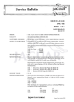
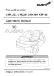
1
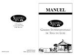
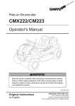
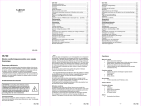
700ATV Maintenance Manual
1
Catalogue
General Information……………………………...5
1 Description…………………………………………………..5
1.1 Identification code………..……………………………..6
1.1.1. Frame No. …………………………………………………6
1.1.2. Engine No.…………………………………………………7
1.2 Special tools, instruments and meters…………………7
1.3 Periodic maintenance chart……………………………….9
Engine………………………………………………………….11
2. Inspection and adjustment of engine…………….11
2.1 Inspection of cylinder head, intake
and exhaust valve………………………………………….11
2.2 Inspection of spark Plug………………………………….12
2.3 Inspection of cylinder, piston and piston ring…….14
2.4 Inspection of crankshaft………………………………….17
2.5 Inspection of clutch……………………………………….18
2.6 Inspection of carburetor………………………………….18
2.7 Inspection of air filter………………………………….19
2.8 Inspection of oil filter………………………………….20
2.9 Inspection of lubrication system……………………….20
2.10 Lubrication of engine…………………………………….21
2.11 Inspection of cylinder head…………………………….21
2
3.Disassembly of engine……………………………………27
3.1 Cylinder head and block………………………………….27
3.2 Piston and connecting rod……………………………….31
3.3 Manual starting mechanism……………………………….32
3.4 Sensor………………………………………………….…….32
3.5 Left crankcase cover……………………………….…….33
3.6 Magneto…………………………………………………..….33
3.7 Oil pump………………………………………….……..….34
3.8 Clutch…………………………………………………...….35
3.9 Carburetor……………………………………………...….36
3.9.1 Structure of carburetor………………………...…..36
3.9.2 Inspection and adjustment of carburetor…....….37
4.Chassis
4.1 Steering operation system………………………...…..39
4.2 Brake system…………………………………………...….51
4.3 Wheels and tires……………………………………...….67
4.4 Transmission system…………………………….…...….70
4.5.gear
gear shift mechanism……………………………………..77
4.6 Suspension…………………………..……....….。。
。。
。.79
5. Electrical system………………………..……....….84
3
5.1 Ignition system…………………………..……....….87
5.2 Magneto and charging system…………..……....….88
5.3 Battery……………………………………..……....….88
5.4 Lighting system…………………………..……....….90
5.5 Meterand signal system…………………………..……91
5.6 Electrical starting system…………….……..…….92
6.Appendix………………..…………………..……....…93
6.1 Specification………..…………………..……....….93
6.2 Requirements for torque of fastener……………….99
6.3 Electrical circuits……………………………....….100
4
General Information
1 Description
5
1.1 Identification code
1.1.1. Frame No.
The frame No. is engraved in the right bottom of the supporting
frame. See Figure 1-1.
Figure 1-1
1.1.2.Engine No.
The engine No. is engraved in the right side of the engine. See
6
figure 1-2
Figure 1-2
1.2 Special tools, instruments and meters
1.2.1 Oil filter detacher
To fasten and detach the oil filter
1.2.2 Height gauge
To gauge the height of various components
1.2.3 Vernier
To measure the length of various components
1.2.4 Outside micrometer
To accurately measure external
diameter of a column
7
1.2.5 Inside micrometer
To accurately measure internal
diameter of a hole
1.2.6 Dial indicator
To accurately measure a small distance
1.2.7 Torque Spanner
To measure torque force
1.2.8 Feeler gauge
To measure gap-width
1.2.9 Multimeter
To check electrical circuits and parts
1.2.10 Barometer
8
To measure pressure of the tyre
1.2.11 Magneto drawing device
To detach the magneto
1.2.12 Snap ring clampTo install
and detach snap rings
1.3 Periodic maintenance chart
EVERY
ITEM
Valves
Sparkplug
Air fiter element
Carburetor*
Crankcase
breathersystem*
Exhaust system*
Spark arrester
Fuel line*
ROUTINE
Whicheve
comes first
INITAL
month
1
3
6
6
12
km
320
1,200
2,400
2,400
4,800
(mi)
(200)
(750)
(1,500)
(1,500)
(3,000)
hours
20
75
150
150
300
○
○
○
○
○
○
● Check valve clearance.
● Adjust if necessary.
○
● Check condition.
● Adjust gap and clean.
● Rep;ace if necessary.
○
● clean.
● Replace if necessary.
Every20-40hours
(More often in wet of dusty areas.)
● Checkandadjustidlespeed/starteroperation.
● Adjust if necessary.
● Check breather hose for cracks of
damage.
○
○
○
○
○
○
○
○
○
○
○
○
○
○
○
○
○
● Replace if necessary.
● Check for lecakage.
● Tighten if necessany.
● Replace gasket(s) if necessary.
● Clean.
● Check fuel hose for cracks or damage.
● Replace if necessaly.
9
Engine oil
Engine oil filter
cartridge
Engine oil strainer*
Final gear oil
Differential gear oil
Front brake*
●Replace.(Wamenginebefore draining.)
○
○
○
○
●Replace.
○
○
○
○
●Clean.
○
○
○
○
● Check for oil leakage.
● Replace eveny 12 months.
○
● Check operation/fuid leakage.(See NOTE
page 8).
○
○
○
○
○
○
○
○
○
○
○
● Correct if necessary.
Rear brake*
● Check operation.
● Adjust if necessary.
Select lever safety
system cable
● Check operation.
● Adjust if necessary.
○
○
○
V-belt*
● Check operation.
● Check for cracks or damage.
○
○
○
○
Wheel
● Check balance/damage/
● Repair if necessary.
○
○
○
○
● Check bearing assemblies for lossenss/
damage.
○
○
○
○
Wheel bearing*
● Replace if necessary.
Front and rear
suspendion*
Steering system*
Drive shaft universal
joint*
● Check operation.
● Correct if necessary.
○
● Checkoperation./Replace if damaged
● Check toe-in./Adjust if necessaly.
● Lubricate
grease.
with
○
○
lithium–soap–bassed
○
○
○
○
○
○
○
Axle boots*
● Check operation.
● Replace if damaged.
○
○
○
○
○
Fittings and
fasteners*
● Check all chassis fittings and fastenrs.
● Correct if necessary.
○
○
○
○
○
Lights and
switches*
● Check operation.
● Adijust headinght beams.
○
○
○
○
○
Engine
2. Inspection and adjustment of engine
2.1 Inspection of cylinder head, intake and exhaust
10
valve
Preheat the engine ,then misfire and unplug the spark
plug.Fix pressure gauge into the hole, open the choke and
throttle handle,and start for 4-6 times.
Note:
Giving
a
leakage
check
to
the
pressure
gauge.Rotate the engine until the pressure gauge
stop rising.The maximum reading would be greater
than 0.7-0.9Mpa after starting for 4-6 times.
See figure 2-1.
Figure 2-1
check the valve lash
Note:when adjust valve lash,the engine must be cooled.
(The tempreture should be less than 35℃ )
Remove the seat cushion and fuel tank,unplug the vision
hole cover ,round the flywheel of magneto anti-clockwise to aim
“T”at the signal of fore cover on the left.
11
Note: The piston must be fixed to the dead enter. (Figure
2-2)
Figure 2-2
Remove cylinder valve cover,check the lash between the
valve stem by feeler gauge .
Valve clearance:inlet and exhaust valve: 0.05~0.08mm.
See figure 2-3.
Figure 2-3
Loose the lock nut,rotate the adjusting screw until it
appears that the feeler gauge be pulled .Then fasten the
adjusting screw by
valve adjuster,tighten the lock nut and
12
check the valve lash
.Afterword install the cylinder valve
cover , vision hole cover,the fuel tank and cushion.
See figure 2-4.
Figure 2-4
2.2
2.2 Inspection of spark Plug
1. Unplug the Spark-Plug cap:remove
the spark plug by box key,look over
whether the spark-plug insulator and
electrode is damaged or sooting.
If so ,see figure 2-5.
Figure 2-5
2. Check the spark clearance
by feeler gauge whether it
is between 0.6~0.7mm.Or adjust
the gap,clean incrustation
with spark-plug cleaner and steel
wire brush and check if
the spark plug sealing washer(Figure 2-6).
Figure 2-6
13
.
item
cylinder
Piston,piston
ring and
piston pin
bore diameter of cylinder
taper
out of roundness
degree of toruosity
external diameter of piston
bore diameter of piston pin
hole
gap between piston pin and
piston pin hole
Piston ring
end
Top ring/the
clearance
second ring
oilring
gap between
piston ring
and piston
groove
connecting
rod
top ring
the second
ring
gap between cylinder and
piston
external diameter of piston
pin
bore diameter
Gap between small end of
connecting rod and piston
pin
standard value:mm
limit value:mm
φ102~φ102.03
0.0040
0.0035
0.04
φ101.95~φ101.97
φ102.1
0.005
0.005
0.06
φ101.92
φ22.002~φ22.010
φ22.010
0.007~0.020
0.02
0.25~0.40
0.5
0.3~0.9
1.2
0.3~0.07
0.10
0.02~0.06
0.09
0.03~0.08
0.09
φ21.995~φ21.990
φ21.96
φ22.016~φ22.027
φ22.03
0.016~0.033
0.035
3.Swirl the when spark plug and tighten to 18~20N.m by box
key ,then fix the spark plug cap when assembling.
2.3
2.3 Inspection of cylinder, piston and piston ring
Camshaft lube is injected by a hole of engine body into
cylinder ,so the hole must not jam.It is necessary to fix
the cushion and adjer without dust permeated into the crank
case before assembly.
14
diagnosing and eliminating of malfunction:
●
Emission of black smoke for abrasion of cylinder
or piston,
1. Cylinder , piston of piston ring is worn out.
2.The piston ring is not properly assembled.
3. The piston or cylinder wall is scraped.
●
overheated
1、Excessive
incrustation of piston.
2、Blast and abnormal noise.
3、Abrasion of cylinder or piston.
Inspection of cylinder.
1.Check whether the cylinder is damaged.
2.Measure the bore diameter of cylinder at three spots.
3.At the top,the middle and the bottom of the piston stroke .And
measure the bore diameter at directions of right-angle
intersection.
repairing limit value:
out of roundness: 0.005 mm
taper :0.005mm
Inspection of piston and piston ring
Measure the gap between piston ring and piston groove.
1.unplug the piston ring;
15
Note:It is forbidden to damaging the piston ring when
assembling.Check whether the piston and the piston groove
is cracked and abraded.See figure 2-7
Figure 2-7
2.Insert piston ring into
cylinder,and measure the
end gap.repairing limit
value:the first ring/the
second ring: 0.5mm
See figure 2-8.
Figure 2-8
Measure the bore diameter of piston pin hole.
repairing limit value:
see figure 2-9
Figure 2-9
16
3.Measure the external diameter 10mm
above the bottom of the piston skirt.
Extreme position :the gap between
cylinder and pistonrepairing
limit value: 0.1mm See figure 2-10
Figure 2-10
Measure the external diameter of piston pin:
the gap between piston and piston pin:
repairing limit value: 0.02mm .See figure 2-11
Figure 2-11
2.4 Inspection of crankshaft
heck that whether crank and connecting rod can rotate
without stuck and whether the clearance between crank and
connecting rod is 0.5~0.6mm.The hop of crank shaft should be
0.05mm.If not so,replace it. See figure 2-12-1, figure 2-12-2.
17
Figure 2-12-1
2.5
2.5 Inspection
Figure 2-12-2
of clutch
The wear condition of shoe block and friction plate:See
figure 2-13
Figure 2-13
2.6 Inspection of carburetor
1、Inspect the idle of carburetor
The engine speed should be 1500±150r/min 10 minutes after
starting at normal idle and will not misfire when briskly
accelerate.If not so, rotate the carburetor idle adjusting
screw clockwise to rise the idle ,anti- clockwise to lower.When
18
adjusting is unavailable,check that if there is a jam in
carburetor idle nozzle or a
air-leakage of intake pipe.
See figure 2-14
Figure 2-14
2.7
2.7 Inspection of air filter
1、Disassemble the air cleaner,remove cartridge,clean the
cartridge with non-flammable cleaning solvent,and then
make it dry.
Note: Petrol is forbidden.
2.Dip the air filter cartridge into 20# oil,then take it
out
and
squeeze
the
excessive
oil,assemble
it
orderly.Impermeability is necessary.See figure 2-15,
figure 2-16.
Figure 2-15
Figure 2-16
19
2.8 Inspection of oil filter
Cleaning of lubricator oil strainer:remove clarifier
(Figure 2-17),clean it to ensure a well work- condition.Then
fix it up.
Note:Clean the clarifier
before injecting
oil
into crankcase.
Figure 2-17
2.9 Inspection of lubrication system
Lubricant of engine:the vehicle is oiled with lubricant
of APISGSAE10W/40.
APISGSAE10W/40. Others are forbidden.
capacity :
The capacity is 1.9L after disassembly and assembly.
2、The capacity is 1.8L when fueling up after drain.
Inspection of
lubricant:locate the dune buggy on the
ground to lookover
the capacity with dip stick.If the
level is lower than the bottom indicator,fuel up with
recommended lubricant to the upper indicator.
Inspection of oil pump:
flow of oil pump:
r/min
1000
2000
3000
L/min
3.78
7.43
10.89
20
measure clearance of the top of internal external rotor
Limit value: 0.20mm
2.10
2.10 Lubrication of engine
Check the oil level,start the engine and let it running for
a fow minutes to make it heated and lubricated completely ,then
misfire.Unplug the dip stick to do cleaning and dip it into the
oil case again.Then unplug the dip stick and look whether oil
level is lower than the indicator. See figure 2-18
Note:Ensure that the engine is landed by both four wheel
in flat ground.
Indicator of oil
level
Figure 2-18
2.11
2.11 Inspection of cylinder head
1.Check whether the spark plug and valve seat is cracked and
whether the
cylinder head is out of shape.Examine the
flatness of cylinder head by flat or knife edge gauge and
clearance gauge .
Repairing limit value:
0.05mm.See figure 2-19
21
Figure 2-19
2 Remove and examine the width of
valve .
Repairing limit value: 2.0mm.
See figure 2-20-1 ,2-20-2, 2-20-3.
If the mating surfaces is coarse,corrode or cannot
contact with valve seat normally.repalce it.
Figure 2-20-1
Figure 2-20-2
Figure 2-20-3
Measure the width of mating surfaces of valve
22
repairing limit value: 1.5mm
If the valve seat is to wide or narrow or cracked,grind
it to ensure impermeability.
4、Measure bore diameter of valve guide with internal micrometer
and special gauge.At last calculate clearance between valve
stem and valve guide.
Repairing limit value: intake : 0.12mm exhaust: 0.14mm
Note
:Eliminate
carbon
in
the
pipe
before
measuring.If the pipe will be replaced,grind the
valve seat again .
5、Inspection of valve and valve pipe:
Check whether the valve is bent,burn or the valve stem is
worn out.
Check the motion of valve and measure external diameter.
Repairing limit value: intake : 5.95mm
exhaust: 5.95mm
See figure 2-21.
Fix valve into guide,and look over the motion.
23
Figure 2-21
Inspection of valve spring
Measure the free height and squareness
Repairing limit value:(intake and exhaust)
See figure 2-22-1, 2-22-2
free
height
of
inlet
valve
spring:
32.5mm,
squareness:0.10mm
free
height
of
exhaust
valve
spring:
36.2mm
squareness:0.10mm
Figure 2-22-1
Figure 2-22-2
6、Examining lifting distance of breaker cam.
Measure the length of fillet with micrometer and check
If it is worn out.
Repairing limit value:inlet lifting distance: 5.73mm
Exhaust lifting distance: 6.53mm.See figure 2-23.
24
Figure 2-23
7、Check whether the
crankshaft journal is worn out and
measure the external diameter of crankshaft journal.
Repairing limit value: φ22.939mm
Inspection of rocker arm.
Check whether the rocker arm is worn out,or damaged and
whether the oil hole is blocked.
Note:If there is a rocker arm to be replaced,examine
the peak of breaker cam
measure the bore diameter of rocker arm
Repairing limit value: φ12.038mm.See figure 2-24
Figure 2-24
7
Inspection of rocker arm shaft.
Examine if the rocker arm if worn out or cracked.
Measure the external diameter of rocker arm shaft with
micrometer.
Repairing limit value: φ11.96mm
25
The repairing limit value of clearance between rocker arm
shaft and hole : 0.05mm ,See figure 2-25
Figure 2-25
3. disassembly of engine
3.1
3.1 cylinder head and block
① Unplug the intake pipe and spark plug.( Figure 2-26-1,
2-26-2)
Figure 2-26-1
Figure 2-26-2
② Remove cylinder valve cover,cam chainwheel cover and
Figure 2-27-1
26
③remove valve chain wheel Figure 2-27-2
Figure 2-27-1
Figure 2-27-2
④remove lower rocker arm shaft.See figure 2-28
Figure 2-28
⑤Remove vision hole cover of left front cover .See figure 2-29
Figure 2-29
27
Alignment: asjust these two "●"symbols of the cam chain
wheel to be at the same level with cylinder cover.
alignmentment of top dead center:
Rorate the crankshaft with “T” sleeve anti-clockwise
until these two "●"symbols of the cam chain wheel to be
at the same level with cylinder cover .That is to say the
piston of cylinder is at the top dead center.
Inspection of compression top dead center:
See figure 2-30-1 and figure 2-30-2.
figure 2-30-1
figure 2-30-2.
When inlet valve spring rise,rotate the crankshaft until
the “T” indicator on the magneto rotor to be at the same
level with the center of vision hole cover of left front
cover.That is to say the piston is at the compression top
dead center and there are valve clearance
in these four
28
rocker arms of cylinder head. See figure 2-31
Figure 2-31
Remove chain tensioner adjuster.See figure 2-32.
Figure 2-32
remove the cylinder head
Loosen the bolt by intersection manner before remove the
bolt.see figure 2-33.
29
Figure 2-33
remove adjuster cotter sealed ring
of cylinder headtensioner
adjuster guide board
See figure 2-34.
Figure 2-34
remove cylinder block0-seal
adjuster cotter
sealed ring of cylinder head
See figure 2-35.
Figure 2-35
3. 2 piston and connecting rod
30
①remove the piston snap ring
Note:block the crankcase breather with a piece of cleaning
cloth to avoid the snap ring falling into the case.See figure
figure
2-36.
Figure 2-36
②remove piston pin and piston
Clean the buckle of piston and piston pin hole to
facilitate the removing of piston pin.
Note:it is forbidden to knock the piston pin with
a hammer.See figure 2-37.
Figure 2-37
31
3.3
3.3 Manual starting mechanism
See figure 2-38.
Figure 2-38
3.4 sensor
Figure 2-39
3. 5 left crankcase cover
See figure 2-40.
Figure 2-40
32
3. 6 magneto
remove the stator coil
remove the pluse coil
Remove the stator with rotor
stripper.See figure 2-41.
Figure 2-41
Remove the whitney key. See figure 2-42.
Figure 2-42
3.7 oil pump
remove the bolt of oil pump cover .See figure 2-43.
Figure 2-43
33
remove right cover
.See figure 2-44.
Figure 2-44
Remove the right support frame,clutch pulley disc .See figure
2-45-1, figure 2-45-2, figure 2-45-3.
Figure 2-45-1
Figure 2-45-2
34
Figure 2-45-3
3.8
3.8 clutch
①remove the clutch
Remove bolts. See figure 2-46.
Figure 2-46
Remove the clutch shoe
block and clutch cover.
See figure 2-47.
Figure 2-47
Check the wear condition
of the clutch shoe block
and clutch cover.
See figure 2-48.
Figure 2-48
35
3.9 carburetor
3.9.1
structure of carburetor
1.carburetor assembly 2.oil needle component 3.Plunger spring 4. Big diaphragm
5.Plunger 6.Diaphragm circlip7.Screw on upper cover 8.Mixture ratio adjusting
screw component。9 .idle metering jet 10.High speed jet 11.Liner 12.Foam pipe
13.0-ring of foam pipe 14.Float 15。Screw M4×816。Float pin 17.Big screw
18.Float seal ring 19.Fuel inlet valve component 20.High speed jet 21.Drain screw
22.idle metering air jet 23.Enriching Plunger component 24.Seal ring of
external shaft cover 25.External shaft cover 26.Screw M4×8 27.Suction pipe A
28.T- plastic pipe 29.Suction pipe B 30.ACV valve diaphragm cover 31.Screw
M4×12 32。Suction pipe C 33.ACV valve diaphragm component 34.Fuel inlet
pipe 35.Starting jet 36.Dust-proof cover 37.Screw 38.Nut 39.acceelerator pull
cablelocating dowel loop 40.adjusting screw component 41.Screw
42.Washer 43.Fixing clamp 44.Washer 45。Screw 46。clip 47.Robber pipe
36
48.Non-return valve 49.Flood pipe
3.9.2
2 Inspection and adjusting he carburetor
decomposition
1.Remove the evacuated chamber cover
2.spring
3.piston valve
remove permanent seat
spring
spring block
oil needle
remove pilot screw
spring
washer
Note:the pilot screw is set at maximum performance.Before
removing pilot screwd,note the revolutions of screw in order
to fix it back.
remove float chamber cover
washer
remove float pin
float
37
triangular needle
remove the cover
nut
0-rings
spring
starting plunger
pilot jet
check the carburetor body
float bowl
oil passage
gas-fouling block→cleaning
chap/damage→replace the carburetor assembly
cleaning steps:
check the float
damaged→replace
check the float triangular needle
triangular needle seat
0-rings
filter gauze
Damaged/worn out/block→replace
check the piston valve
crack→replace
38
diaphragm
rupture→replace
piston valve oil stick
bent/worn out→replace
Note:If the piston valve is damaged,inject the petrol into
valve.Replace it when there is oil leakage.
check the main jet
main jet
pilot jet
pilot screw
0-scrapers
pilot jet
bent/worn out/damaged→replace
gas-fouling block→blow with compressed air
4.Chassis
4.1 Steering operation system
Structure of Steering Vertical Column
39
1、steering vertical column components
Steering Bar Clip
2、turning rocker arm components
3、
4、hexagon flange bolt M8×35
5、inner and external bearing of steering vertical column
steering vertical column
9、stop reverse piece
7、Supporting stent
8、hex
10、Supporting Collar Sheath
6. supporting seal ring of
bolt M8×60
11、cushionф14×ф32×4
12、
Hexagon open-groove nut M14
13 cotter pin 3.2×32
open-groove nut M10
14、tension rod assembly
15、、cushionф10
16 Hexagon
17 cotter pin
Components of Steering Bar
40
1、Steering Bar
components
2、steering Rubber Sheath
3、air duct door pull cable 4、oiler
5、acceelerator pull cable components
6、left switch components
4.1.1Disassembly,
4.1.1Disassembly, inspection and assembly of Steering
Vertical Column
4.1.1.1Disassembly of Steering Vertical Column
41
1.Remove all of the Plastic cover and Plastic oranments
on Steering Bar (Figure 4-1-1
1). Front Mud Shield
2).Plastic Ornament
3).Rear Mud Shield
2.Remove Steering Bar Holder
(Figure 4-1-2)
Figure 4-1-1
1). Hexagon Flange Bolt M8×30
2).Steering Bar Holder
3).Steering Bar Clip
3.Unplug all cables and connecting
wires and remove the Steering Bar
(Figure 4-1-3)
Figure 4-1-2)
1)Connecting Wire
2)Rear Brake Cable
3)Front Brake Cable
4)Steering Bar
4.Remove the cotter pin,
Figure 4-1-3)
open-groove nut and
cushion at the bottom
42
of the Steering Vertical Column. (Figure 4-1-4)
1).cotter pin 3.2×32
2).cushionф14×ф32×4
3).Hexagon open-groove nut M14
5、Remove the supporting
brackets of the steering
vertical column
Figure 4-1-4
(Figure 4-1-5)
1)Supporting stent
2)Inner and outer supporting
Bracket
3)safety cushion
Figure 4-1-5
6.Remove outer ball pin
components on tension
rod form turning joint
(Figure 4-1-6)
Figure 4-1-6
1)Tension rod
43
2)front right Yanggakdo
3)cotter pin 3.2*32
4)Hexagon open-groove nut M10
7.Pull out the components of
the steering vertical column
from the bottom seat.
( Figure 4-1-7)
Figure 4-1-7
1、 Steering
2、 Bottom
Vertical Column
Seat
4.1.1.2 Inspection of steering vertical column components:
1.Check whether the nut between
the inner ball pin of tension
rod and the Turning rocker arm
is tightened.( Figure 4-1-8)
In case of loosen or worn out,
tighten it with proper tools or
replace with identical nuts.
Figure 4-1-8
Torque: 32-36N.m
1)Steering drop arm assembly
2)Hexagon open-groove nutM10
44
3)cotter pin 3.2*32
4)Tension rod
2.Check whether the inner and outter ball pin of the tension
rod is loosen or got stuck. (Figure 4-1-8)
In occasion of above defects, further inspection of the
exact causation must be carried out and replace with new
ball pin components.
Caution: Continuous use of defective ball pin
might cause severe injury or death.
3.check whether the tension rod is bended, cracked or
rusted. In occasion of above problems, please have the
tension rod replaced.
Caution: tension rod should not be repaired by
welding .
4. Check whether the hexagon open-groove nut and cottor pin
are intact. (No crack or flaw is allowed)(Figure 4-1-8).
Those two components are crucial and should be replaced
whenever there is a potential problem.
5.Check whether the supporing bracket is firmly fixed to
the steering vertical column. Figure 4-1-5
Inspection method:
45
Assemble the steering vertical column to the main frame
with supporting bracket and M8 bolts etc. and rotate the
steering bar to ensure the column is not stuck or swinging.
In occasion of above problems, the supporting bracket
must be replaced.
Rotating Torque of the steering vertical column:
3-5N.m
4.1.1.3 Assembly of steering vertical column
a、Firstly,fix the Turning rocker arms comp into the
steering vertical column.Then plug the steering
vertical column into the bottom seat and fix it with
M14 open-groove nut (1pcs), φ 14 × φ 36 × 4 cushion
(1pcs), collar sheath (1pcs) and 3.2×32 cotter pin
(1pcs)( Figure 4-1-9).
Fastening
Torque
of
M14
open-groove
nut:
70-80N.m
Caution: before inserting the steering vertical column
into the bottom seat, both upper and lower oil
seals
must
be
greased
with
lithium
lubrication.
46
Figure 4-1-9
1)、Steering bottom seat
2)、Cushion
3)、Hexagon open-groove nut M14
4)、Cotter pin 3.2×32
2.Fix the steering vertical column onto the frame with hexagon
flange bolt M8*60 (2pcs), supporting stent (1pcs), inner and
outer supporting bracket (2pcs), stop reverse piece (1pcs) and
collar pipes (2pcs). (Figure 4-1-10)
Fastening Torque of M8*60 Bolt: 26-30N.m
Caution: inner surface of the supporting brackets
must be greased with lithium lubrication.
47
Figure 4-1-10
1)、 hexagon flange bolt M8*6
2)、Inner and outer supporting bracket
3)、stop reverse piece
4)、Supporting stent
5)、Supporting Collar Sheath
6)、Supporting ferrel
4.Fix the tension rod into the conical bore of the steering
vertical column with tension rod components (2sets), cushion
φ12 (2pcs), M10 hexagon open-groove nuts (2pcs) and cotter
pins 3.2×32 (2pcs). Figure 4-1-11
Fastening Torque: 28N.m
Figure 4-1-11
1)Turning rocker arms comp
2)Cushion ф10
3)Hexagon open-groove nut M12
4)Cotter pin 3.2×32
48
4.1.2 Disassembly, inspeciton and assembly of steering bar
4.1.2.1 Disassembly of steering bar
1.Remove all of the Plastic cover and Plastic oranments
on Steering Bar (Figure 4-1-1)
2.Remove steering bar clip(附图4-1-2)
3.Unplug all cables and wires and remove the steering
bar (Figure 4-1-3)
4.1.2.2 Inspection of steering bar
1.Check any existing or potential crack on the steering
bar. In case of above defects, the steering bar must
be replaced(Figure 4-1-12)
Figure 4-1-12
2.Altitude balance on each end of the steering bar
must be less than 3mm, otherwise replace the
steering bar. Figure 4-1-12
49
3.Check if there exists any slip thread, crack or other
defects on the fastening bolts, in which case the
bolts must be replaced.
4.Check
whether
the
steering
bar
clip
is
damaged(Figure 4-1-12).(Radial runout and wear
condition of the inner surface must be less than
0.8mm) Otherwise, replace the steering bar clip.
4.1.2.3 Assembly of the steering bar
1.Connect the steering bar, clip and holder with the
main frame by hexagon flange bolts M8*30 (4pcs) and
adjust the direction of brake cables on both left and
right handlebar and clutch cable(Figure 4-1-2)
Fastening Torque of the M8*30 Bolt is: 26-30N.m
4.2
Brake System
4.2.1Front Disk Brake components
50
1、disk brake pump assembly
washer
2、disk brake compressed bearing
3、disk brake oil bowl sealing
4、disk brake oil bowl cover
5、cross recess half-countersunk head screw M5×12
pan head screw M5×60
9、hexagonal locknut M8
6、disk brake pump seat
7、cross recess
8、disk brake handle
10、disk brake switch
11、disk brake handle bolt 12、disk brake oil
pipe branch seat
13、 front disk brake pipe 14、rear brace of front hydraulic pipe
15、inner hex
bolt栓 M6
×10
16、bolt of front hydraulic pipe
17、front hydraulic disk brake cushion 18、Hexagon Flange
Bolts M6×25
19、Hexagon Flange Bolt M8×14
20、Hexagon Flange nutM8
21、rear brake piece 22、brake-fluid
case
4.2.1 Preparation for inspection and maintenance of the front
disk brake system.
1.
Brake system is crucial to the life safety of the operator
and
therefore
must
be
periodically
inspected
and
maintained.
The vehicle uses brake plate. Please follow the tips of
51
inspection as below:
a)Inspect the brake fluid box level
on the right handlebar. Should
the fluid level falls under
the minimum mark, please refill
the box with the same type
of fluid as was recommended
by the manufactureFigure 4-2-1
to ensure the fluid level
(Figure 4-2-1
1)、Brake fluid box
is higher than the minimum mark.
b)Travel distance of the front brake lever should be kept
between 10mm-15mm. Otherwise, please adjust the screw to meet
required travel distance. Figure 4-2-2
Figure 4-2-2
1、Adjusting Screw
c) Inspect the elasticity of the brake handlebar.
52
d))Brake fluid will be automatically injected into the
brake fuel pipe in the process of abrading brake pad
reducing the fluid level in the box. Therefore,
periodical inspection of the fluid level is necessary.
Caution: must use DOT4 Brake Fluid
e) Periodical inspection of the wear condition of
front disk brake plate is also necessary.
Disk brake plate must be replaced depending on its
wear condition. Figure 4-2-3
Caution: 1. If the thickness of the disk brake
plate is less than 1.5mm, it must be replace.
2. In occasion of crack or distortion, the
disk brake plate must be replaced.
Figure 4-2-3
1)Brake plate clip
2)Hexagon self-lock nut M8
53
f)Disk brake plate uses hydraulic pressure of the brake
fluid. Therefore, fuel pipe must be periodically
inspected and replaced.
Inspection Method: Fuel pipe must be replace when
worn out, cracked or distorted.
4.2.1.1 Disassembly, inspection, maintenance and assembly of
Front Disk Brake System.
4.2.1.2 Disassembly of front disk brake plate
1、Removing the wheel component see Figure 4-2-4
1)front wheel hub
2)Hexagon open-groove nut M30
3) cotter pin 3.2*32
4)cushion
5)taper nut M10
Figure 4-2-4
2.Sequently remove the cotter pins,
open-groove nuts, cushion and front
wheel hub from the front wheel shaft.
(Figure 4-2-4)
3.Remove the disk brake
plate from the front wheel hub.
(Figure 4-2-5)
1)disk brake plate
54
2)Rront brake plate clip
4.2.1.3 Disassembly of the Front Disk Brake system:
1.Remove the bottom seat
of Disk Brake Pump and
then remove the whole unity.
Figure 4-2-6
Figure 4-2-6
1)bottom seat of Disk Brake Pump
2)Disk Brake Pump unity
2、Remove the Front Fuel Pipe Brackets(Figure4-2-7)
Figure4-2-7
1).branch seat of Disk Brak Fuel Pipe
2).Hexagon Flange Bolts M8
3.Detach
the
Plate
Clip
nut
and
remove
the
Plate
Clip(Figure4-2-3).
4、 Remove the Rront brake plate system(Figure4-2-3)
4.2.1.4Inspection of the Front Brake System
55
1.Check the Brake Fluid Box for crack, leakage and other
potential defects.
2.Check Fastening Bolts of all Fuel Pipes for possible
looseness or damage.
3.Check all Fuel Pipes for deterioration, distortion,
crack, wear and other hidden defects.
4.Check the Brake Plate Clip for distortion, crack, rust
and stuck.
5.Inspect the Brake Shoe for wear condition. Brake shoe
must be replaced when worn out. (Figure 4-2-8)
Figure 4-2-8
1) Brake Shoe
6、 Inspect the Brake Shoe for maximum wear, distortion
and crack, in which case it must be replaced.
Maximum wear of Rear Disk Brake Plate is less than
56
1.5mm
4.2.1.5 Assembly of Front Brake System
1.Use Fuel Pipe Brackets (2pcs) and Hexagon Flange
Bolts M8*16 (2pcs) to connect the Fuel Pipe Clip with
both left and right Lower Front L/R rocker armss.
Caution: Fuel Pipe must avoid physical contact
with other components in movement.
2、Fix the Disk Brake Plate onto the Front Wheel Hub
with M8 Special Bolts (4pcs) (Figure 4-2-4)
Caution: grease the bolt with thread glue when
fastening.Fastening
Torque
of
the
Bolt:
22N.M-26N.m
3、 Fix the Front Wheel Hub onto the Front Wheel Shaft
with open-groove nuts and cotter pins. (Figure 4-2-4)
Fastening Torque of Open-groove nut:
50 N.m—60N.m
4、 Fix the Plate Clip onto Front Turning Joint with
M8 Bolts (4pcs)
Fastening Torque: 18 N.m --22 N.m
5、Assemble Front Wheel Components onto Front Wheel
Hub with M10 Conical Nuts of GB/T802 (4pcs) (Figure
57
4-2-15)
Fa
stening Torque of Conical Nut: 55 N.m -40N.m
6、Fix Front Disk Brake Pump onto the Right Handlebar
with M5*60 hexagon bolts (2pcs) (Figure 4-2-16)
astening Torque of the bolt is: 10 N.m --14 N.m
Caution: Do not operate the vehicle immediately
after assembling the brake system. Please apply
the Brake Lever several times to fully engage
the Disk Brake Plate and have the Brake Fluid
circulating before riding the vehicle
4.2.2.Rear
4.2.2.Rear Brake System
4.2.2.1Preparation for inspection and maintenance of the Rear
Brake System
58
a)
Brake system is crucial to the life safety of the
operator and therefore must be periodically
inspected and maintained.
b)Rear wheels of the vehicle use brake plates
mechanized by a rear brake pedal. Please follow
the tips of inspection as below.
c)Inspect the brake fluid box level on the right
handlebar. Should the fluid level falls under the
minimum mark, please refill the box with the same
type of fluid as was recommended by the manufacturer
(Figure 4-2-9) to ensure the fluid level is higher
than the minimum mark.
Figure 4-2-9
1、Minimum Mark
d)Travel distance of the Rear Brake Pedal should be kept
between 20mm-30mm. Otherwise, please adjust the screw
to meet required travel distance.( Figure 4-2-10)
59
e)Inspect the elasticity
of the brake handlebar.
f)Brake fluid will be
automatically injected
into the fuel pipe in
Figure 4-2-10
1、Rear Brake Pedal
the process of
abrading brake pad
reducing the fluid level in the box. Therefore,
periodical
inspection
of
the
fluid
level
is
necessary.
Caution: must use DOT4 Brake Fluid
。
g)
Periodical inspection of the wear condition of
front disk brake plate is also necessary.
Disk brake plate must be replaced depending on its
wear condition. (Figure 4-2-11)
60
Figure 4-2-11
1、Disk Brake Plate
Caution: 1. If the thickness of the disk
brake plate is less than 2.5mm, it must
be replace.
2.
In
occasion
of
crack
or
distortion, the disk brake plate must
be replaced.
h)Disk brake plate uses hydraulic pressure of the brake
fluid. Therefore, fuel pipe must be periodically
inspected and replaced.
Inspection Method: Fuel pipe must be replace when worn
out, cracked or distorted.
4.2.2.2
Disassembly, Inspection and Assembly of Rear Disk Brake
System:
4.2.2.3 Disassembly of Rear Disk Brake System
61
1.detach Rear Disk Brake Pump from the Frame
(Figure 4-2-6)
2.Remove Rear Disk Brake oil bowl from the Frame
(Figure 4-2-9)
3.Release assembling
Bolt(M8*14) and
detach the Rear Disk
Brake Clip. (Figure 4-2-12)
Figure 4-2-12
1)Rear Disk Brake Clip
2)hexagon flange bolt M18×14
4、Remove Rear Disk Brake System
4.2.2.4. Disassembly of Rear Disk Brake Plate
1.remove rear wheel components(Figure 4-2-13)
2、Release the transmission
case components of rear bridge
from the main frame.Remove
rear central transmission shaftv
components. (Figure 4-2-14)
Figure 4-2-13
1)Conical Nuts M10
2)Wheel Hu
3、Remove the Bottom Seat
62
of Rear Disk Brake Plate
from the Rear Bridge.
(Figure 4-2-14)
Figure 4-2-14
1)hexagon flange bolt M10×115
2)rear transmission case
3)rear central transmission shaftv
3.Remove the Rear
Disk Brake Plate from
Bottom Seat see
Figure 4-2-15
Figure 4-2-15
1).Bottom Seat of Rear Disk Brake Plate
2)Rear Disk Brake Plate
4.2.2.5Inspection of Rear Brake System:
1、Check the Brake Fluid Box for crack, leakage and other
potential defects.
2、Check Fastening Bolts of all Fuel Pipes for possible
looseness or damage.
63
3、Check all Fuel Pipes for deterioration, distortion,
crack, wear and other hidden defects.
4、Check the Brake Plate Clip for distortion, crack, rust
and stuck.
5、Inspect the Disk Brake Shoe for wear condition. Brake
shoe must be replaced when worn out.
1、Brake Shoe
6、Inspect the Brake Shoe for maximum wear, distortion
and crack, in which case it must be replaced.
Maximum wear of Rear Disk Brake Plate is less
than 2.5mm
4.2.2.6 Assembly of Rear Brake System
1Fix Disk Brake Plate onto the Bottom Seat with Special M8 Bolts
(6pcs).
Caution: Grease the bolt with thread glue
64
when fastening
Fastening Torque of bolt: 22 N.m -28N.m
2、Mount the Bottom Seat of Rear Disk Brake Plate onto rear
transmission case .Then configure the rear central
transmission shaft, rear transmission case in turn. See
Figure 4-2-15
3、 Mount the Disk Brake Clip onto rear transmission case with
M10×30 Bolts (2pcs)
Fastening Torque: 18 N.m--22 N.m
4、
Mount Fluid Box of Rear Disk Brake onto the Frame with
M Bolt (1pcs).
Fastening Torque: 8 N.m—12 N.m
5、Mount Rear Disk Brake Pump onto the Frame with M Bolts (2pcs).
Fastening Torque: 22 N.m—26 N.m
6 Fix front wheel hub onto the front wheel shaft with cushion,
open-groove nuts and cotter pins.
Fastening Torque: 50 N.m—60 N.m
7.Assemble Front Wheel Components onto Front Wheel Hub with M10
Conical Nuts( GB/T802) (4pcs).
Fastening Torque of Conical Nut: 55 N.m - N.m
65
Caution: Do NOT operate the vehicle immediately
after assembling the brake system. Please
apply the Brake Lever several times to
fully engage the Disk Brake Plate and have
the Brake Fluid circulating before riding
the vehicle.
4.3 Wheel and Tyre
4.3.1:Preparation for maintenance of wheel:
1.Inspect wear condition
of the tyre.
(Figure 4-2-16)
2.Check if the Wheel
Hub is worn-out or
damaged. (Figure 4-2-13)
3.Check if the Wheel Hub
is rusted or cracked.
Figure 4-2-16
4、Check if the conical
nuts of the Wheel Hub
are loosen or distorted.
4.3.2
Disassembly,
inspection
and
assembly
of
wheel
components:
66
4.3.2.1 Disassembly of wheel components:
Remove M10 Conical Nuts (4pcs) and detach the tyre.
(Figure 4-2-13)
4.3.2.2 Inspection of wheel components:
1.Check if the wheel hub has any distortion, rust, crack or
other potential defects. If so, please replace the wheel hub.
2、Check if the tyre has reached its maximum wear condition in
which case it should be replaced.
3、Check the joining condition of the tyre and wheel hub. If
the joint of tyre and wheel hub is loose, replace the tyre
immediately.
4、Check the vibration of tyre/wheel hub. (Figure 4-2-13)
Vibration
of
assembled
Tyre
must
be
controlled within 3mm. Otherwise, please
replace with new tyre.
Remove the tyre for vibration test of the
wheel hub. Should the vibration exceed
1.2mm, the wheel hub must be replaced.
5、Inspect the four conical bores on the wheel hub.
In occasion of angular distortion or wear, the wheel
hub must be replaced.
4.3.2.3 Assembly of wheel:
67
Attach wheel hub onto the wheel with M10 Conical ball
Nuts (4pcs)and dust-proof cover.(1pcs).
Fastening Torque: 45~55N.m
Caution: assemble the wheel in correct direction
(shown as the arrow). Front and Rear Wheels
are not interchangeable. (Figure 4-2-17).
4.3.2 Speicification and
operation guide of Wheel
Hub and Tyre.
Since wheels and tyres
are crucial to the
Figure 4-2-17
vehicle operation, periodical inspection for tyre
pressure and profile depth is necessary.
Specification of Wheel and Tyre
Wheel Hub
Dimension
Tyre
Dimension
(kPa)Tyre
Pressure
Front
Wheel
12×6
25×8-12
35
Rear
Wheel
12×8
25×10-12
35
To ensure maximum security and longer life expectancy of the
wheel, please periodically inspect the tyre pressure and
68
profile depth. Insufficient tyre pressure can result in not
only intensified wearing of the tyre but also instability
during the course of operating the vehicle (such as hard
turning). Excessive tyre pressure can also reduce the friction
force between the tyre and ground, causing spinning or lose of
control. Therefore, please ensure the tyre pressure strictly
complies with figures shown in the chart above.
Before operating the vehicle each time, please check if
profile depth of the tyre is over worn, which might result in
spinning, instability, lose of control and other potential
security risk of the vehicle.
Caution: Should the profile depth falls below 3mm,
please replace the tyre inmediatly.( Figure
4-2-18)
Figure 4-2-18)
4.4 Transmission System
4.4.1 Fore Bridge
69
Figure 4-2-19
1 、 front wheel hub
2 、 L/R transmissionshaft 3 、 fore bridge differential
components 4、middle transmissionshaft components of fore bridge
5、L/R turning joint
front tank components
1、gear-box assembly of front bridge 2、 the right cover
10.5 5、drive gear of front bridge
3、the left case
4、cushion φ
70
6、front driving axis pin sleeve 7、M10X1.25 flange locknut 8、0-ring of front
bridge drive gear f9、φ65Xφ48oil seal 10、oil seal of rear constant velocity
joint assenbly 11、differential –adjusted washer
12、M8X20 engine gearbox bolt 13、differential assembly 14、inner hex bolt M8X25
15、inner hex bolt M8X10 16、hexagon flange bolt M10×25
17、clip used inφ66 18、φ5X80 cylindrical pin 19、engine gearbox assembly 20、
adaptor 21、cog rack
22、fork 23、0-rings of engine gearbox 24、0-rings of front cover
25、deep-groove
ball bearing6007
26、deep-groove ball bearing 6912 27、deep-groove ball bearing 16007
28、needle bearing15BM2112 29、M10X16 oil-change bolt 30、φ10X1.5 cooper gasket
31、power divider coupling
32、differential-adjusted washerⅡ 33、bolt M14X15
34、cooper gaske φ14X2 35、vent piepe of drive case 36、clip of oil pipe 37、
fore transimmision shaft
38、weak spring of fore transimmision shaft
39、dust-proof cover of fore transimmision shaft
4.4.1
Disassembly, inspection, assembly of Rear Bridge
components(refer to the
figure of fore Bridge ,fore
case components)
4.4.1.1
1. Check if the connection between wheel hub and the Bottom
Seat of wheel hub is reliable and if there is any
distortion on the Bottom Seat of wheel hub.If there
exists any such potential defects, the Bottom Seat of
wheel hub must be replaced immediately.
2.Check if the Yanggakdo and its attachements are
compatible well and if there is stagnation ,slosh and
Crunch of the Yanggakdo bearing.In case the bearing or
Yanggakdo is flawed ,the fore bridge must be removed
in the first instance,then replace the bearing and
Yanggakdo.
71
3.Check if the constant velocity joint is matched up well.
If not so or there is gear-cracked and abnormal
noise,remove the constant velocity joint and align
it .
4.Check if there exists any slip thread or flaw on the
open-groove nut .
5..Disassemble the front tank and check whether the gears
Is engaged properly.
6..In case the choke is jammed,it must be dredged with
a needle.If the problem is not solved,replaced it.
7.If there are defects on sensors ,it must be checked and
maintained by a professional.
8. Gears is fragile commondities in transmission system.
4.4.1.2 Disassembly of fore bridge component:
1.Detach the two front wheel parts.
2.Removed front Disk Brake Clip, cotter pin, cushion and
the front wheel hub. (Figure 4-2-20)
Figure 4-2-20
3.disassemble the fore bridge differential( Figure 4-2-20)
72
4、Take out the fore bridge from the frame
5、Release engine oil in the differential
6
、
Unplug
the
transmissionshaft
from
the
of
the
differential( Figure 4-2-19)
4.4.1.3
Inspection and Maintenance of fore bridge:
1.If
the
dust-proof
Rubber
Sheath
transmissionshaft is worn out or cracked, plesae have
it replaced immediately.
2、Check whether the ball is running smoothly. If found
loosen or stunk ,replace the transmissionshaft.
3 、 Disassemble the transmissionshaft,clean
,then
install,
Caution:1. The dust-proof Rubber Sheath can not be
touched by petrol and diesel oil.
2
The dust-proof Rubber Sheath must not
becracked for slight scratch may be
damaged the Rubber Sheath.
3.Inject 2/3 Lithium Lubrication into the
ball.
4 、 Open the differential, and inspect wear condition of
73
gear,shaft and cushion,then replace the defective
component.
4.4.1.4
assembly of fore bridge component
1、Fix transmissionshaft onto fore bridge differential.
( Figure 4-2-19)
2、Inject 0.32L of GearLubricant of SAE 80 API GL-4 into
fore bridge differential.Then tighten the bolt.
Torque of the bolt: 23N.m
3、Fix the fore bridge differential onto the frame with
hexagon flange bolt M10×110 (2pcs), M10 nuts (2pcs),
cushion 10 (2pcs) ( Figure 4-2-21).
Fastening Torque of the Bolt is
40~45N.m.
( Figure 4-2-21)
1、 hexagon flange bolt M10×110
74
2、 fore bridge case
4.4.2 Rear Bridge
4.4.2.1transmissioncase of rear bridge
1、rear bridge transmission case assembly
2、the left case
3、needle bearing 22BM3010
4、
needle bearing 55BM6720A
5、cluster gear of rear bridge
6、needle bearing
7、rear disk brake seat
8、φXφ
75
oil seal
9、clamp sheath
10、0-ring of rear drive gear
11、cushionφ12
12、nutM12X1.25
13、rear drive gear
seat
14、rear adjuster cushionⅠ 15、rear adjuster cushionⅡ
hole
18、hex
bolt M8X35 19、cushionφ8 20、hex
alloy oil cap 23、case cover of rear bridge
φ8
16、oiling plug 17、0-rings of grease
bolt M8X25 21、cushionφ8 22、zinc-base
24、inner hex
26、flange nut M8 27、hexagon flange bolt M8X12
bolt M8X45 25、cooper gasket
28、cooper gasketφ8
29、φ90X
φ65 oil seal
30、deep-groove ball bearing 16017
washerⅢ
31、0-rings of rear bridge
cover 32、rear adjuster
33、hexagon flange bolt M10X25
34、rear bridge oil-change
plug M14X15 35. cooper gasketφ14 36. weak spring of rear
bridge transimmision shaft 37. rear bridge transimmision shaft 38. external clipφ
18
39. sheath of
rear bridge transimmision shaft
40. external clipφ18φ18
41.clip 42.
fore
dust-proof cover of rear bridge transimmision shaft
43. rear dust-proof cover of rear bridge transimmision shaft 44. bypass line
The maintenance of rear bridge is identical to the fore
bridge.Please refer to the preceding contents.
4.5 gear shift mechanism
1、gear shift mechanism assembly
2、gear shift mechanism handle
3、换档机构
76
plastic screw of gear shift mechanism
4、dust-proof cover of gear shift mechanism 5、dust-proof cover thimble of gear
shift mechanism 6、elocity joint robber sheath of gear shift mechanism
7、velocity joint of gear shift mechanism 8、hex nut(anti)M8 9、waste oil pipe
thimble of gear shift mechanism
10、waste oil pipe of gear shift mechanism 11、waste oil pipe thimble of gear shift
mechanism 12、waste oil pipe robber plug of gear shift mechanism
13、hex nut (upright)M8 14、connecting rod of gear shift mechanism 15、hex nut
(anti)M8
16. gear shift controling
17. cushionφ6 18. hex nut M6×36
4.5.1Inspection
Inspection and Maintenance of gear shift Mechanism(refer
to the picture of gear shift Mechanism)
1.Check the mobility of gear shift handle. If it is not working
properly, remove the gear shift Mechanism to check if the
fork , ball and spring is stuck.,in which case replace the
defective component and try again.The last way is to turn to
the professional repairman.
2.If there is lack in the gear shift mechanism , adjust the nut
of the fork to correct position and strengthen gear shift
mechanism .
3.Remove the gear shift mechanism and check whether the linking
rod is cracked; If so, it should be changed.
4.Check whether the bouncing spring of gear shift mechanism is
intense enough.
5.Check whether the gear is engaged correctly and whether
there are tripstop or lack. If these situation exists, call for
77
the maintanance staff to test and repair it.
6.If the gear can not be engaged, we can test it from the
following aspects: ① whether the clutch can completely
declutch; ②
whether
the
gearshift
is
greased
reliable(whether the oil pipe of gear shift mechanism is
blocked) ③
whether gear shift mechanism jams;If these
situation happens, maintanance staff would come to test and
repair it.
4.6
Suspension
4.6.1components of rear Suspension
1、rear damper components
2、hexagon flange bolt M10×50
3、locknutM10×1.25
78
4、horizontal rear-fin components
5、 the right horizontal rear-fin velocity joint
6、the left horizontal
rear-fin velocity joint
7、locknutM12×1.25 8. horizontal rear-fin robber
sheath 9. horizontal rear-fin press plate 10. hexagon flange bolt M8×14
4.6.2rear rocker arm
1、rear left-upper rocker arm assembly 2、middle spacer sleeve of fore L/R
rocker
arm
3、hexagon flange bolt M10×65
4、dust-proof cover of rear rocker arm
5、rear left-upper rocker arm assembly 6、middle spacer sleeve of fore L/R
rocker
arm 7、hexagon flange bolt M10×65
8、ust-proof cover of rear rocker arm
9、rear left-bottom rocker arm assembly 10、middle spacer sleeve of fore L/R
rocker arm 11、hexagon flange bolt M10×65
12、rear left-bottom rocker arm assembly 13、middle spacer sleeve of fore L/R
rocker arm 14、hexagon flange bolt M10×65
15、hex locknut M10×1.25 16、cover of rear left-bottom rocker arm 17. hexagon
flange bolt M6×12
18. cover of rear right-bottom rocker arm
19. hexagon flange bolt M6×12
79
4.6.3.front Suspension
1、fore upper-left rocker arm
2、middle spacer sleeve of fore L/R rocker arm
3、fore upper-right rocker arm assembly 4、middle spacer sleeve of rocker arm
5、open-groove nut M10
6、cotter pin 3.2×32
7、fore bottom-left rocker arm
assembly 8、fore bottom velocity joint assembly
9、stopper elastic ring for shaft 10、middle spacer sleeve of fore L/R rocker
arm 11、fore bottom-right rocker arm 12、fore bottom velocity joint assembly
80
13、stopper elastic ring for shaft 14、middle spacer sleeve for security 15、
hexagon flange bolt M10×40 16、hex locknut
17、elastic cushion 18、hexagon flange bolt M10×65 19、hex locknut M10×1.25
20、fore L/R damper 21、hexagon flange bolt M10×50 22、hex locknut M10×1.25
23、cover of fore bottom-left rocker arm 24、cover of fore bottom-right rocker arm
25、hexagon flange bolt M6×12 26、holding plate nutM6
4.6.4
Disassembly, Maintenace and Assembly of
up-and-dowm rocker arm 1、Disassembly and Maintenace
Collar Sheath,cotter pin and damper may easy to occor problem.
A、If the L/R rocker arms swing easily, we can test it from the
following aspects:whether the collar sheath is defective by
pressuer and whether the Rubber Sheath is worn out or cracked
B、Check whether the cotter pin is reliable.If not so ,replace
it.
C 、 The main problems and homologous maintenance are as
following:check whether the spring is split or the oil will
spill out in which case the damper muse be replaced and test
if the oil bowl is excellent without damage in different
circumstances.
2、Disassembly(as the following picture)
Mount fore L/R damper,up-and-down rocker arm assembly onto
the frame with Hexagon Flange Bolt M10×65 (8pcs), M10 nuts
(8pcs),
Hexagon
Flange
Bolt
M10 × 50
(4pcs)and
M10locknuts(4pcs)to ensure a torque of 40~45Nm.
81
Caution:A:These components should be greased with butter
before assembly.
B:The surface of components can not be cracked.
Check whether these components are greased with butter and then
tighten the up-and-down rocker arm assembly and L/R fore
dampers and ther components.Fix the L/R tension rods into hole
by way of the trough of
open-groove nut with cotter pin(4
pcs),and make these tension rods bisection on feet.
82
4.6.5.Inspection and Maintenance of rear Suspension
1.Inspection and Maintenance are similar to the fore Suspension
2.Check whether the assemble shaft of
the rear damper
is
deformed in which case it must bu changed.
3.Check the Collar Sheath and Rubber Sheath
4.Check if the cotter pin on the assembly shaft of the rear
damper is reliable.
Caution:
Disassemble rear damper and check if the damper and
the connecting hole is bent or cracked. In case of above
defects,call for professional staff or replace the
damper and then tighten the bolt(Note: self-lock nut
is necessary and the torque must be at a range of
45~
55 N.m)
5.Electrical system
Route color indication
1.Black┄┄B
2.Red┄┄R
18.Blue White┄┄L/W
19.Blue Black┄┄L/B
83
3.Yellow┄┄Y
4.Green┄┄G
5.Orange┄┄O
6.White┄┄W
7.Gray┄┄Gr
8.Blue┄┄L
9.Brown┄┄Br
10.Dark Green┄┄Dg
11.Dark Red┄┄Dr
12.White Green┄┄W/G
13.White Red┄┄W/R
14.White Black┄┄W/B
15.Light Blue┄┄Lb
16.Light Green┄┄Lg
17.Black Yellow┄┄B/Y
20.Red Black┄┄R/B
21.Red White┄┄R/W
22.Green White┄┄G/W
23.Brown White┄┄Br/W
24.Brown Blue┄┄ Br/L
25.Red Brown┄┄R/Br
26.Yellow Red┄┄Y/R
27.Green Red┄┄G/R
28.Green Black┄┄G/B
29.Black White┄┄B/W
30.White Blue┄┄W/L
31.Yellow White┄┄Y/W
32.Green Blue┄┄G/L
33.Purple┄┄V
Troubleshooting and repair
No electrification:1. First, Check the safety.
2. Second, if the safety is good, then check the battery
whether it is power on.
3. Finally, check the switch lock and electric route, whether
they are bad.
Other troubleshooting and causations as follows
84
85
phenomena
cause
1,no spark
1.switch lock
※carve out a way or
ignition system
measure
short
circuit,connection
badness
※
line
bonding
badness
2.CDI set
※
After electrify no
noise from the CDI
3.high voltage
※ high voltage lead
insulated badness
※high voltage lead carve
out a way or short
circuit
4. magneto
※ signal loop and charge
loop
remark
★repair
★repair
★replace
★repalce
★repalce
★repalce
carve out a way or
short circuit
electrification
system
2 .
spark
weak
or
sparkover
intermittence
1. spark plug
※
pollute or wear
intermittence
2. high voltage bag
※high voltage lead wire
insulated badness
1,discharge
self
1. cover polluted
drenched by rain
or
2, uncharge or
shortage-charge
★repalce
★replace
★
water-proof,keep
clean of the
cover and repalce
electrolyte
1.carve out a way or
short circuit, caused
by connected wire
badness
2.rectifier damaged
3.baterry
※lower-electrolyte
★repair
★repalce
★
entered
distilled water
★replace
※electrode failure
1. flash not
bright or weak
1. the switch of flash lamp
or
emergency
light
contacted badness
2. lamp
※ filament of lamp
damaged
※ the watt of lamp larger
or smaller than regulated
★ repair
replace
or
★replace
★replace
86
5.1 ignition system
The key diagram of ignition elements ignition elements:
Ignition pressure provided by magneto ignition coil
through diode commutated,by R(red line)input CDI(capacitance
discharge ignition),charge to capacitance C.at the same
time ,spring coil produce spring signal ,provided to SCR as the
turnon spring signal ,when reaching the ignition timing,SCR
turnon capacitance began to discharge at the elementary coil
L1 caused instant lower pressure ,while at the secondary coil
caused
induce
pressure.its
instant
pressure
up
to
10000V,sparkover at the clearance of sparkplug(0.6mm).so the
engine ignited
charge system
87
The key diagram of charge elements
5.2 magneto and charge system
the elements of charge:
When
the
engine
running,driven
magnet
rotor
circumgyrate,so on the stator coil produce alternating current
then induce electromotive force come into to being the
pressure.Through
3
lines
Y(yelloe
)
output
into
the
rectifier ,through rectifier into direct current pressure and
output.through R1 to charge the battery.
5.3 Battery
Under the following problems, please change the battery
1. With long time charge but the pressure do not increase to
a set value.
2. At the bottom of case there is something dirty or electrode
have become white or the case with a sulfate function
88
3. Electrode former scratched or scratched by press or
insulation without work.
Pay attention when using
1. Long time out of using but without charge is not correct.
2. Too much charge (so long time charge is not correct,
generally if battery empty, the normal charge time hours)
3. Do not charge under a much higher pressure or electric
current
4. Keep battery at a low temperature and dry place
5. Charge battery before fix it.
If battery without electrolyte, it may cause the
rectifier damaged. And the electrolyte is venomous
and dangerous. As it contains vitriol it may cause
burn accident. Battery also contains explode gas, so
keep it far away spark and flame and cigarette. When
charge or using in house, keep the air easy floating.
When work near the battery, please take care of your
eyes and keep kids away from the battery.
If under such accidents, please deal with it as follows or
ask for help from the doctors.
89
1. Exterior, wash lots of cleaning water
2. Interior, drink milk or water and then milk of magnesia or
egg or rap oil and hospitalize as soon as possible.
3. Eyes, wash cleaning water at least 15 minutes and hospitalize
as soon as possible.
5.4: Lighting system
function
fast
and
near
light
swith
white
blue
black
yellow red
yellow
green
/green
black /red
black
blue
yellow gray
dark dark
green brown
green
/red
green
/black
light
green
red
/white
flashing
relay
OFF
switch
white
green green dark dark
gray brown
/black /red brown green
red2
green
red
stating
urgnt
switgh OFF
magneto
turnning
switch
white white white
OFF
horn
switch
rectification
regulator
blue
green dark dark yellow
/red browngreen
black red1
front
brake
switch
12V 3W
meter
indicator
light
black
rear
brake
switch
blue/white
starting
button
dark
green
dark
dark
brown green
dark
brown
15A
M
B
M
yellow
yellow
/green
/green
yellow green yellow green blue yellow2
red
biue
/black1
purple
oil
temperature
indicator
light 12V 1.7W
oil
front
temperature
light1
switch
12V 18W
battery
12V 12Ah
black
brown
functionred1 brown
/blue
switch
brown
red
/ brown /blue
red
/white
yelow
/red
front
light2
12V 18W
rearlight/brakelight
front left
right
turn
light
12V 5W/21W
;5A(2.4 draver);25A(Ignition)
;10A(signal)
;25A( frontlight)
black
black
whole safety box
black
left
right
turn
indicator
light
rearleft
right
turn
light
black
black
black
black
12V 10W
the key diagram of illumination system
5.5 Meterand signal system
90
:Operation and working way:
1、 Headlight
Headlight Switch
yellow
function /red yellow green
2、 Emergency light switch
green green
/black
function /red
3、Turing light switch
function gray nigger
brown
dark
green
OFF
When using this function, left and right turning lights will
shine at the same time.
Meter
meet an emergency, the lamp is red (do not
shine)
4、Horn Switch
function yellow light
green
/red
function
yellw blue
/red /white
biue
OFF
91
When press the button, the horn will move. But if without sound
or with unclear sound or with little sound please check the
problem according to the guide
5.6:Electrical starting system
Starting Circuit
Starting system working process
Turn on the start switch on the left handlebar, the battery
can supply power for the CDI. Then the CDI supply power for the
startor relay, then the power from the battery can be sent to
the startor motor through the startor relay and the startor
motor works help the engine to work.
Note:
1. When electrical starting, please keep the battery with
enough power and the time of pressing button will be within
92
55 seconds. If longer time more than 5 seconds, it may cause
the damange of startor relay and the startor relay motor
and may also cause the damage of the battery that it can
not be charged or not charge enough.
2. When starting, if heard some noises from the startor
relay, the battery must be without enough power. Please
stop starting and change a powerful battery or charge for
it.
3. If the startor motor can not work normally, please check
according to the 2 rule to see if it is not lubricated enough
6.Appendix
6.1 Specification
6.1.1 Table of specification
a)Specification of vehicle
Overall length
2250mm
Overall width
1210mm
Overall height
1225mm
Wheel base
1365mm
Wheel gauge
900mm
Ground clearance
260mm
Seat height
930mm
Mini. turning radius 2000mm
Suspension
Front:Hydraulic spring swing arm
Rear:Hydraulic spring swing arm
Braking pattern
Front
dual
disk,
Rear
single
93
(Normal condition)
disk/front and rear linkage, Right
foot/left hand operation
Braking
pattern Front
dual
disk,
Rear
single
Primary Brake(1): disk/front and rear linkage, right
(E-mark)
foot/right hand operation
Front
Primary Brake(2):
dual
disk,
Rear
single
disk/front and rear linkage, right
foot/right hand operation
Emergency brake:
Parking brake:
Wheel Hub
hand operation
Engine/ hand operation,Gear shift
handle
Front:Alloy/ Steel wheels
Rear:Alloy/ Steel wheels
Tyre dimension
Front 25x8-12 (Vacuum Tyre)
Rear 25x10-12 (Vacuum Tyre)
Tyre pressure
Front 35kpa
Rear 35kpa
Fuel tank Vol.
17L±0.1L
Dry weight
319kg
Max. loading weight
180kg
G.V.W.R
509kg
Max. loading weight
(Hitch):
100kg(EMARK)
Total
weight(including
609kg(EMARK)
hitch):
b)Engine specification
Engine Model/Brand
HS1102MU/ HSUN
Pattern
Single cylinder, water cool, dual
94
exhaust, four stroke
Bore×Stroke
102mm×84mm
Compression Ratio
9.2:1
Volume
686ml
Max. power
25kW (5000r/min- 5500r/min)
Max. power(E-mark) 13kW (5500r/min)
Rated power
24kW
(6000r/min-6500r/min)
Max. Torque
49N·m (5000r/min)
Max. Torque(E-mark) 27.5N·m (4500r/min)
Mini. Idle speed
1400±100r/min
Fuel type
Unlead #90
Lubrication
Pressure Splash
Starting system
Electric Start and hand recoil start
Ignition
C.D.I
Drive train
Axle
Transmission
CVT
Belt drive r
atio:
L Drive
5.0695~0.7679
5.3595 ( 30/17 × 41/21 ×
ratio: 24/18)
H Drive
3.2230 ( 26/21 × 41/21 ×
ratio: 24/18)
R Drive
3.8282 ( 25/17 × 41/21 ×
ratio: 24/18)
Engine Drive
ratio:
16.339~2.475
Clutch
Wet automatic centrifugation
Lubrication
Comply
(Crankcase)
Depending on regional weather condition,
with
GB11121-1995
standard.
95
choose either SAE 5W-40 or SAE 10W-30
(Cold region)SAE.20W-40(Warm region)
Oil capacity
1.9L
Engine dry weight
71kg
c) Components Specification
Carburetor
PD42J
Pattern
Parallel Vacuum
Spark plug
DR8EA
Speed meter
Electronic
Battery
12V 21Ah
Headlight
12V 35W/35W
White light
Front Indicator
12V 3W
White light
Rear Indicator
12V 5W
Red light
Brake light
12V 21W
Red light
12V 5W
White light
12V 10W
Amber light
Rear license plate
light
Turning light
Rear reflector
Red light
d)Other specification
Turning
operation
system
Hand operating steering bar
Two wheel/ four wheel drive (2W means
Driving method
two wheel drive, 4W means four wheel
drive)
96
Rocker arms
Front and Rear dual rocker arms
Parking brake
Mechanical
Frame
Steel pipe
Magneto
Rotate DC output
Spark plug gap
0.6-0.7 mm
Safety fuse
30A
6.1.2 Performance Requirement
a) Starting Performance
Starting time must be less than 15s
b) Accelerating Performance
Starting
acceleration
performance
must
be
less
than
14s/200m,,and overtaking acceleration performance must be less than
13s/200m.
c) curb-top speed
Crest speed must be less than 90km/h(the Crest speed of E-mark must
be less than 80km/h )
d) grade climbing
Climbing cpacity must be greater than 22°
e) minimum specific fuel consumption
minimum specific fuel consumption should be less than 340g/Kw·h
f) reliability
The reliable travelled distance is 6000km.It may be tested by
GB/T 5374-1995
g) durability
The durability distance travelled distis 16000km, It may be
tested by GB/T 5374-1995
h) emission
The emission limit must be conform to GB 14621-2002 and GB
14622-2002
97
a) idle emissions
CO≤3.8 %,HC≤800 ppm
b) mode emissions
CO ≤ 7.0 g/km,HC≤1.5g /km,NOx≤0.4 g/km
i) deceleration and stopping performance
a) braking distance : ≤27m(starting velocity is 60km/h )
b)braking deceleration must be greater than 5.88m/s2
j) noise
The aon running noise must be less than 79dB (A).
Static noise is 94dB (A),and the eagine speed is 2750mim2.
k) radio-frequency interference
The allowable radiation , the loss of suppress of ignition
system and the radio-frequency interference must be conform to GB
14023-2006。
l) parking performance
When using the parking brake on neutral,the parking brake
system must enable
the vehicle motionless
in both straight and
reverse at a grade way of which the grade of slope is 18% and the
adhesion coefficient between tyre and road must be greater than 0.7.
m) antisway angle
。
The greatest antisway angle to the left and right at unladen or
motionless must bu greater than 25°.
n)
distance headlamp performance:
p).
The dune buggy must be equipmented with distance headlamps that
conform to GB 5948-1998 or GB 4599-94.
q). The main beam intensity of distance headlamp must reach a digree
98
of 8000cd.
6.2 Requirements for torque of fastener
fastening parts
(N.m)torque
pillar
35~45
nut on chain stay
45~50
Upper nut on fore damper
35~45
bottom nut on fore damper
35~45
Upper nut on rear damper
45~55
bottom nut on rear damper
45~55
Nut on upper rocker arm of the
40~50
left
Nut on bottom rocker arm of the
40~50
left
Nut on upper rocker arm of the
40~50
rignt
Nut on bottomr rocker arm of
40~50
the rignt
Suspension nut
35~45
Nut connecting chain stay and
40~50
rocker support
Nut on fore wheel
45~55
99
Nut on rear wheel
45~50
6.3 Electrical circuits
the characteristic of the electrical circuits,
1.Actualize the electrial starting when it is at N,parking and
brake.
2.When it is in the H gear,the H gear switch of the engine is
on the ground,the H gear is lighting by the CDI inner transistor
to control the dash light earth connection.
3.The function of the diode in this circuitry is that after
parking and brake to actualize the electrial starting .
4.The relay electrical source,to provide the electricity
through the CDI working,it can protect the relay and to extend
the useful time.
5.Use the pan- fuse box,each operating circuit is working
independence,and easy to service,there is no connect with the
inner cable and the functional line,it is hard to emerge the
dummy section.
100
OVERRIDE
CDI
30A
m mn
i 1000
FUEL
L2
L1
101