1
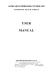
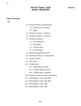
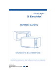
Repair Guideline for SANYO New Erp
DC Inverter Air Conditioner
(Published in May, 2013)
KRV-09TDAA, KRV-12TDAA, KRV-16TDAA,
KRV-18TDAA, KRV-22TDAA, KRV-24TDAA
Contents
I. Electronic Control of DC Inverter Air Conditioner ·················································2
1. Main parts of the electronic control of DC inverter air conditioner····························2
2. Wiring of DC Inverter Unit ··········································································3
3. Current Flow ···························································································3
4. Software Control Function Flow Chart ····························································4
5. Fault Codes (including quick solutions) and Protection codes ·································5
II. Troubleshooting ·························································································8
1. According to the fault code ··········································································8
(1) Display E1 or E2: ····················································································8
(2) Display E6 ····························································································9
(3) Display E3, E7, E8 ··················································································9
(4) Display E4 ····························································································10
(5) Display EC ····························································································10
(6) Display EP ····························································································11
(7) Display EA ···························································································12
(8) Display EU ···························································································12
(9) Display E9 (Firstly display P0 or P9, then change to E9) ······································13
(10) Display E0、E5 ····················································································14
(11) Display EE ··························································································15
(12) Display EF ··························································································16
(13) Display EH ··························································································16
(14) Display P0 ···························································································17
(15) Display P1 ···························································································17
(16) Display P2 ···························································································18
(17) Display P4 ···························································································18
(18) Display P5 ···························································································19
(19) Display P6 ···························································································20
(20) Display P7 ···························································································21
(21) Display P8 ···························································································22
(22) Display P9 ···························································································23
2. Other faults·····························································································24
1) The indoor unit works normally but the outdoor unit does not work. ·························24
2) The outdoor unit is stopped when the air conditioner has run for a period of time ·········24
3) The air conditioner is tripped when it is started. ·················································24
4) The complete unit does not work ···································································24
Appendix 1 ··································································································26
Appendix 2 ··································································································35
Appendix 3 ··································································································38
Cautions on Replacement of PCB Boards·······························································40
1
I. Electronic Control of DC Inverter Air Conditioner
1. Main parts of the electronic control of DC inverter air conditioner
The electronic control of DC inverter air conditioner is composed of indoor control system and
outdoor control system. All the units 9k/12k/18k/24k apply 180° sine wave technology, and
indoor control system are controlled by outdoor control system.
For 9k and 12k, the outdoor PCB is divided into two parts, i.e. outdoor power source board and
Intelligent Power Module (IPM). Note: Power Factor Correction (PFC) is integrated in IPM.
IPM board
Outdoor power source board
For 18k and 24k, the outdoor PCB is divided into three parts, i.e. outdoor power source board,
Power Factor Correction (PFC) board and Intelligent Power Module (IPM).
IPM board
PFC board
Outdoor power source board
2
2. Wiring of DC Inverter Unit
Or
Wh
BL
BL
Transformer
Br
Br
Or
Indoor main
PCB
Display PCB
board
Y/G
Y/G
BL
BL
4-way Valve
Motor
protector
Relay
BR
BL
Y/G
Electric
Heater
Optional
Indoor fan Motor
Heat exchanger
Room temperature
sensor
Y/G
Electronic
valve
Or
Vane motor for
flap
Pipe coil temperature
sensor
Indoor unit
Reactor
BL
BL
Re
PFC
Compressor
Re
Re Wh BL
BL
IPM
Re
Compressor top protection switch
(Optional)
BL
Fan
motor
Re
Br
Outdoor power source board
Y/G
Exhaust temperature sensor
Re
BL
Outdoor temperature sensor
Outdoor coil temperature sensor
Note: There is no LOW FAN for single-speed motor P9-2
Port: P9 pair port for dual-speed motor
Outdoor unit
(For 9k/12k, PFC is integrated in IPM. )
3. Current Flow
Live
Power
supply
Outdoor
Neutral
Unit
Ground
Neutral
Live
Live
Main
control
board
PFC board
Neutral
Communicati
on wire
Ground
Indoor
Outdoor
power
source
board
Compressor
IPM board
unit
(For 9k/12k, PFC is integrated in IPM. )
3
4. Software Control Function Flow Chart
Indoor control system
Indoor control board
Communication with outdoor unit
Indoor fan control
Vane motor control
Temperature sensor
Fan speed feedback
Electric heater control
Selection of cool-heat and cool-only
model
Selection of data sheet
Selection of Fahrenheit and
Centigrade temperature
Selection of LED or without LED
display
Signal input
Display PCB board
Temperature or fault code display
Emergency Switch signal input
Remote signal input
Outdoor control system
Live
Neutral
Communi
cation
wire
IPM module
Outdoor power source board
Storage of working parameters
Frequency generation
Outdoor temperature detection
Communication with indoor unit
Outdoor fan control
4-way valve control
Outdoor power treatment
Power ON/OFF
Communication with IPM
Fault and compressor state
indication
Switch signal on top of the
compressor
Chassis heating control
Electronic expansion valve control
Pressure switch signal processing
Voltage sampling
(For 9k/12k, PFC is integrated in IPM. )
4
Signal
wire
Communication with power
source board
Compressor drive
IPM fault output
Commu
nication
PFC control
DC power
Outdoor PFC board
AC rectifier
Power factor adjustment
Protection current sampling
5. Fault Codes (including quick solutions) and Protection codes
Fault Codes
(If the error code indicated on display PCB is not in the below list, the display PCB may be
broken.)
Digital
Indoor
LED
Function
display
Indicator
Fault Type
Quick solutions
(Please try the tips one by one, not all at the same time. )
(flash)
E0/E5
RUN & TIMER:
Indoor/outdoor
1 Check the wire connection from indoor to outdoor, and among outdoor PCBs.
Blink/ RUN-5/8
communication fault
2 Check if the LED indication light on outdoor power source board is on. If the
(The most frequent fault
light is not on, replace outdoor intelligent board when outdoor voltage is 220V, and
means possible problems
replace indoor main PCB when outdoor voltage is not 220V.
in
If the light is on, and E0 is showed on display PCB before compressor running,
sec.
the
indoor/outdoor
communication
indoor
PCB,
connecting
from
through
wires
replace the indoor main PCB, and then the outdoor PCB boards, and then
indoor/outdoor connecting wires.
and
If the light is on, and E0 is showed on display PCB after compressor running
to/among outdoor PCBs.)
several minutes, replace the indoor/outdoor connecting wires, then indoor/outdoor
PCBs.
EC
RUN & TIMER:
Blink
Outdoor
PCB’s
communication fault
1 Check the wire connections among all outdoor PCB boards.
2 Replace intelligent power module board.
3 Replace power source board.
E1
RUN-1/8 sec.
Indoor room temperature
1 Check the wire connection of indoor temperature sensor assembly.
sensor (IRT)
2 Replace indoor temperature sensor assembly.
3 Replace indoor main PCB.
E2
RUN-2/8 sec.
Indoor
pipe
(coil)
temperature sensor (IPT)
1 Check the wire connection of indoor temperature sensor assembly.
2 Replace indoor temperature sensor assembly.
3 Replace indoor main PCB.
E3
RUN-3/8 sec.
Outdoor
pipe
(coil)
temperature sensor (OPT)
1 Check the wire connections of outdoor temperature sensor assembly
2 Replace outdoor temperature sensor assembly.
3 Replace outdoor power source board.
E4
RUN-4/8 sec.
System abnormal
1 Check if high pressure valve and low pressure valve open
2 Check if refrigerant is in short, and then recharge.
3 Check if temperature sensor on outdoor condenser loose or broken.
4 Replace the indoor main PCB.
E6
RUN-6/8 sec.
Indoor fan motor fault
1 Check if indoor cross fan runs normally.
2 Check if wires of indoor fan motor connect indoor main PCB well.
3 Replace indoor main PCB.
4 Replace indoor fan motor.
E7
RUN-7/8 sec.
Outdoor
temperature
sensor
1 Check the wire connections of outdoor temperature sensor assembly
2 Replace outdoor temperature sensor assembly.
3 Replace outdoor power source board.
E8
RUN-8/8 sec.
Exhaust
sensor
temperature
1 Check the wire connections of outdoor temperature sensor assembly
2 Replace outdoor temperature sensor assembly.
3 Replace outdoor power source board.
5
E9
RUN-9/8 sec.
Intelligent power module
1 Replace intelligent power module board.
of drive and module fault
EF
EA
RUN-10/8 sec.
RUN-11/8 sec.
Outdoor fan motor fault
1. Replace the outdoor power source board
(DC Motor)
2. Replace the outdoor DC fan motor
Current sensor fault
1 Find the leakage point and recharge the refrigerant.
2 Replace power source board.
EE
RUN-12/8 sec.
EEPROM fault
1 Check if the EEPROM on indoor main PCB or outdoor power source board
installed well.
2 Replace indoor main PCB.
3 Replace outdoor power source board.
EP
RUN-13/8 sec.
Temperature switch fault
1 Check if wires of compressor connect outdoor power source board well.
(on
2 Replace outdoor power source board.
top
of
the
compressor)
EU
RUN-14/8 sec.
Voltage sensor fault
1 Check the wire connections between power source board and intelligent power
module.
2 Replace power source board.
EH
RUN-15/8 sec.
Outdoor
intake
temperature sensor
1 Check the wire connections of outdoor temperature sensor assembly
2 Replace outdoor temperature sensor assembly.
3 Replace outdoor power source board.
You are suggested to change the whole outdoor PCB box for 9K/12K in the final user’s house. :
Protection Codes
(Protection codes mean protection from the machine automatically. The machine usually can
recover by itself; otherwise it will change to fault codes. Protection codes have little possibility to
occur, so we do not list the quick solutions as below. )
Digital LED
Indoor function Indicator (flash)
Protection Type
display
6
P1
RUN: Blink; TIMER: 1 blink /8 sec
Overvoltage / undervoltage protection
P2
RUN: Blink; TIMER: 2 blink /8 sec
Overcurrent protection
P4
RUN: Blink; TIMER: 4 blink /8 sec
Exhaust overtemperature protection
P5
RUN: Bright; TIMER: 5 blink /8 sec
Subcooling protection under cooling mode
P6
RUN: Bright; TIMER: 6 blink /8 sec
Overheating protection under cooling mode
P7
RUN: Bright; TIMER: 7 blink /8 sec
Overheating protection under heating mode
P8
RUN: Bright; TIMER: 8 blink /8 sec
Outdoor overtemperature/ undertemperature protection
P9
RUN: Blink; TIMER: 9 blink /8 sec
Intelligent Power Module protection (software control )
P0
RUN: Blink; TIMER: 10 blink /8 sec
Intelligent Power Module protection (hardware control)
Display on outdoor power source board: The indicator alerts the fault in a cycle as such that it is
bright for 0.5 seconds, dark for 0.5 seconds, blinks “n” times and then dark for 3 seconds.
It is not easy to count the blink times, so it can only be the assistant to Fault and Protections codes
and only useful for professional technicians.
Blink
Blink
Fault Message
Fault Message
times(n)
times(n)
Short-circuit / open-circuit fault of intake temperature
1
IPM protection
18
sensor
2
Overvoltage / undervoltage
19
Outdoor EEPROM fault
3
Overcurrent
20
Outdoor fan motor protection
4
Exhaust overtemperature protection
21
Indoor fan motor protection
5
Outdoor coil overtemperature protection
6
Drive fault and protection
23
System in shortage of Freon
7
Communication fault with indoor unit
24
Model configuration wrong
25
Indoor sensor fault
26
Indoor coil sensor fault
27
Indoor EEPROM fault
28
Indoor fan motor fault
30
drive fault(V4、VP2)
-
-
Compressor overheat fault (compressor top
8
switch)
Short-circuit / open-circuit fault of outdoor
9
temperature sensor
Short circuit / open-circuit fault of outdoor heat
10
exchanger temperature sensor
Short-circuit / open-circuit fault of exhaust
11
temperature sensor
12
Voltage sensor fault
Outdoor environmental
13
Current sensor fault
31
overtemperature /
undertemperature protection
14
IPM fault
32
Indoor coil deforst prevention
33
Indoor coil overheating protection
communication fault between power source board
15
and intelligent power module
16
No feedback from DC fan motor(outdoor unit)
17
Defrost state
7
II. Troubleshooting
1. According to the fault code
(1) Display E1 or E2:
Symptom
Display E1 or E2
Cause
Indoor temperature sensor assembly
S/N
1
Inspections
How to Solve
Check the connection of indoor
Insert again if loose.
Remarks
room temperature sensor assembly
to CN6(RT、IPT) on indoor main
PCB
2
Measure the resistance on the two
Replace the temperature sensor
ends of indoor temperature sensor:
if the resistance is not in
(25℃/ 5KΩ). For other resistance,
standard level
please refer to the Temperature –
Resistance Sheet (Appendix 1).
3
If the above testing is normal
Replace the indoor main PCB
Check the connection of indoor room
temperature sensor assembly to CN6(RT、
IPT) on indoor main PCB
Measure the resistance of
indoor temperature sensor
8
(2) Display E6
Symptom
Display E6
Cause
Indoor fan motor fault
S/N
Inspections
How to Solve
Remarks
If the fan does not run, adjust the
1
Check the indoor cross fan blade
fan position until it can run
smoothly.
Check the connection of indoor fan
2
motor to CN3, CN4 on indoor main
Insert again if loose.
PCB
3
The above inspections are normal
Replace the indoor main PCB
(3) Display E3, E7, E8
Symptom
Display E3, E7, E8
Cause
S/N
Outdoor temperature sensor assembly fault
Inspections
How to Solve
Check the connection of outdoor
1
Insert again if loose.
temperature sensor to CN1, CN2 on
outdoor power source board
Measure the resistance on the two ends of
Replace the temperature sensor
outdoor temperature sensor:
assembly if the resistance is not
Resistance of CN1 terminal sensor –
in standard level.
(25℃ / 5KΩ). For other resistance, please
2
refer to the Temperature – Resistance
Sheet.
Resistance of CN2 terminal sensor –
(25℃ / 20KΩ). For other resistance,
please refer to the Temperature –
Resistance Sheet.
3
If the above testing is normal
Replace outdoor power source
board
9
Remarks
(4) Display E4
Symptom
Display E4
System abnormal: Let the compressor run for 5
minutes. If the indoor coil temperature cannot
Cause
be 2℃ lower than that before the compressor is
started (2℃ higher for heating mode), it can be
judged as the system is abnormal.
S/N
1
2
Inspections
Check
the
How to Solve
high-pressure
and
Remarks
If not open, open again to ensure
low-pressure valves.
the system circulation is smooth.
Check refrigerant volume. If no
Check the leakage point and
obvious temperature change after
recharge the refrigerant.
running 5 minutes in cooling mode,
the system is in shortage of
refrigerant.
3
Check the indoor evaporator pipe
Replace the temperature sensor
coil
if the resistance is not in
temperature
sensor
(25℃/5KΩ). For other resistance,
standard level.
please refer to the Temperature –
Resistance Sheet.
4
Replace the indoor main PCB.
If the above inspections are normal
(5) Display EC
Symptom
Display EC
Outdoor communication fault between power source
board and intelligent power module
How to Solve
Remarks
Cause
S/N
1
Inspections
Check the contact of communication wire
(CN5) between power source board and
intelligent power module
Insert again if loose.
Replace intelligent power module. If
2
If the above inspections are normal
still not solved, replace outdoor power
source board.
10
(6) Display EP
Symptom
Display EP
Compressor temperature switch fault ( on top
Cause
S/N
1
of the compressor)
Inspections
Check the connection of the
compressor top temperature switch
wires to CN3 on outdoor power
source board
2
3
Remarks
Insert again if loose.
Jumper short-circuiting (This
function not provided for 9k/12k
unit)
No switch on compressor top
If
the
compressor
temperature
is very high,
with
bad
smell.
How to Solve
Check the U, V and
W wires of the
compressor.
Connect again if incorrect.
Check the system
pressure.
The pressure is low. Add
refrigerant to ensure the system
pressure is normal.
Check if anything
blocks the outdoor
ventilation
and
radiating
Install to the position as required
in the Instruction Manual and
ensure the air inlet and outlet of
the outdoor unit is smooth.
If compressor temperature is not
high.
11
Replace the
source board.
outdoor
power
(7) Display EA
S/N
Symptom
Display EA
Cause
Current sensor fault
Inspections
1
Check if refrigerant leakage
2
If still not solved,
How to Solve
Find the leakage point and
recharge the refrigerant
Replace the
source board
outdoor
Remarks
power
(8) Display EU
S/N
1
Symptom
Display EU
Cause
Voltage sensor fault
Inspections
How to Solve
Replace the outdoor
source board
Voltage sensor fault
12
Remarks
power
(9) Display E9 (Firstly display P0 or P9, then change to E9)
Display E9 (Firstly display P0 or P9, then
Symptom
change to E9)
Cause
S/N
Intelligent power module fault
Inspections
How to Solve
Remarks
If this code is displayed when the compressor is
started for several seconds or even not started,
If no insert wrong, replace the
check
intelligent power module
the
compressor
connection
for
correctness
Check
if
the
outdoor
module is tightly installed
off
onto the radiating fins and
then,
if the silicone is applied
Power
and
1
power
on,
check
the
code
display.
Firstly
display P0
evenly
Check
protection
on
Fix the screws again if loose.
“P0”
when
appears
the
conditioner
the
system
pressure.
working
is low. Discharge some refrigerant if
the pressure is too high.
air
is
Recharge refrigerant if the pressure
Check
the
outdoor
ventilation and if there is
Install to the position as required in
any
that
the Instruction Manual and ensure
normal
the air inlet and outlet of the outdoor
obstruction
affects
the
radiating
of
the
air
unit is smooth.
conditioner.
The above inspections are
normal,
but
the
fault
remains unsolved
Replace
the
intelligent
power
module
If this code is displayed when the compressor is
Power off
started for several seconds or even not started,
If no insert wrong, replace the
check
intelligent power module
the
compressor
for
correctness
Cooling
and then,
2
connection
/
heating
is
normal during run
the
intelligent
power
module
power on,
P9 appears after
check the
the air conditioner
protection
is started and has
If the cooling / heating is
code on
run for a period of
abnormal,
check
the
display.
time
compressor
wiring
for
Firstly
Replace
Be sure to apply
silicone when
Insert again if loose.
replacing
intelligent
correctness.
power module.
display P9
When the compressor is restarted immediately
after stop, this might also cause P9 protection
because the cooling system is not stable.
13
Try to start the air conditioner again
after a longer period of stop
(10) Display E0、E5
Symptom
Display E0、E5
Cause
Indoor / outdoor communication fault
S/N
Inspections
How to Solve
1. Check if the indoor and outdoor connections are correct.
The terminal L and N shall correspond to each other on
indoor and outdoor units. Measure the voltage on outdoor
Replace the indoor main PCB
terminal L and N (before display of E0 fault). If the voltage
is “0”:
2. If the L & N voltage is normal, measure the voltage
Energize
and
observe
for
approx.
10
1
between the outdoor terminal N and 1. If the voltage
change occurs between 0~24V (change pulse voltage)
3. If the L & N voltage is normal, measure the voltage
between the outdoor terminal N and 1. If the voltage
Replace the outdoor power source
change occurs between 0~12V( change pulse voltage), but
board
there is no 24V:
minutes.
4. If the L & N voltage is normal, measure the voltage
If E0 is
between the outdoor terminal N and 1. If the voltage has no
always
change:
changed
to E5
after a
period of
time:
5.
Indicator
on
outdoor
power
source
board
Firstly replace the indoor main
PCB. If the fault remains unsolved,
replace the outdoor power source
board.
displayed
or
Replace the indoor main PCB.
1) Check if PFC board damaged
If damaged, replace PFC board.
2) If no damage, test the DC voltage
between DC+ and DC-. If the voltage
is approx. 300V:
Replace the power source board.
3) If no damage, test the DC voltage
between DC+ and DC-. If the voltage
is zero:
Replace the PFC board
Firstly replace the intelligent power
6. If the problem cannot be solved by using the
methods above:
module. If the problem remains
unsolved, replace the indoor main
PCB, power source board, and PFC
board
14
Remarks
(11) Display EE
S/N
1
Symptom
Display EE
Cause
EEPROM fault
Inspections
Power off and then power on, if the
fault remains, it is needed to check
if the indoor and outdoor EEPROM
installation is loose.
How to Solve
Fix again
2
If the installation is good:
Replace the indoor main PCB
3
If the fault remains unsolved after
replacement of the indoor control
board:
Replace outdoor power source
board
Indoor unit EEPROM
Outdoor unit EEPROM
15
Remarks
(12) Display EF
Symptom
Display EF
Cause
Outdoor fan motor fault (DC motor)
S/N
Inspections
How to Solve
1
Check if the outdoor power source
board is broken
Replace outdoor power source
board
2
If not solved by above mothod
Replace outdoor DC fan motor
Remarks
(13) Display EH
Symptom
Display EH
Cause
Outdoor intake temperature sensor fault
S/N
Inspections
How to Solve
1
Check the wire connections of
outdoor
temperature
sensor
assembly
Fix again
2
Check
the
outdoor
intake
temperature sensor (25℃/5KΩ).
For other resistance, please refer to
the Temperature – Resistance
Sheet.
Replace outdoor
sensor assembly.
3
If the fault remains unsolved
Replace outdoor power source
board
16
temperature
Remarks
(14) Display P0
Symptom
Display P0
Cause
Intelligent Power Module protection
Inspections
How to Solve
If this code is displayed when the
compressor is started for several seconds
or even not started, check the compressor
connection for correctness.
Power
off
and
then
power
on,
check
the
protection
code
on
display.
Firstly
display P0
“P0” appears
when the air
conditioner
is working
Remarks
If no insert wrong, replace the
intelligent power module
Check if the outdoor
intelligent power module
is tightly installed onto
the radiating fins and if
the silicone is applied
evenly.
Fix the radiator again if loose.
Check
the
pressure.
Recharge refrigerant if the pressure
is low. Discharge some refrigerant if
the pressure is too high.
system
Check
the
outdoor
ventilation and if there is
any obstruction that
affects
the
normal
radiating of the air
conditioner.
The above inspections
are normal, but the fault
remains unsolved
Install to the position as required in
the Instruction Manual and ensure
the air inlet and outlet of the
outdoor unit is smooth.
Replace
module
the
intelligent
power
(15) Display P1
Symptom
Display P1
Cause
Overvoltage / undervoltage protection
S/N
Inspections
How to Solve
1
Test the supply voltage if it is
between 160V ~260V(AC).
It is normal protection
exceeding this range.
if
2
Test if the voltage between L and N
terminal of outdoor unit is within
160V~260V(AC).
It is normal protection
exceeding this range.
if
3
If the voltage is normal:
Replace the
source board
17
outdoor
Remarks
power
(16) Display P2
S/N
1
2
Symptom
Display P2
Cause
Overcurrent protection
Inspections
Check if the outdoor fan motor is
stopped due to overheat protection,
or damaged, and if the fan capacitor
is damaged.
How to Solve
Remarks
Replace the damaged capacitor
and the damaged outdoor fan
motor.
Replace the intelligent power
module.
Intelligent power module damaged
(17) Display P4
S/N
1
2
3
4
Symptom
Cause
Inspections
Display P4
Exhaust overtemperature protection
How to Solve
Remarks
Install to the position as required in
the Instruction Manual and ensure
the air inlet and outlet of the
outdoor unit is smooth.
Check if the air inlet and outlet of
outdoor unit is blocked by any
obstruction.
Check the system for shortage of
refrigerant.
Check if the exhaust temperature
sensor is not in standard level
(25℃/20KΩ). For other resistances,
please
refer
to
the
Exhaust
Temperature Sensor – Resistance
Sheet)
Add refrigerant
Replace
outdoor
sensor assembly
temperature
Replace the outdoor power source
board
Outdoor power source board damaged
18
(18) Display P5
S/N
1
2
3
4
Symptom
Cause
Inspections
Display P5
Subcooling protection under cooling mode
How to Solve
Remarks
Install to the position as required in
the Instruction Manual and ensure
the air inlet and outlet of the
outdoor unit is smooth.
Check if the air inlet and outlet of
indoor unit is blocked by any
obstruction.
Check the system for shortage of
refrigerant.
Check if the exhaust temperature
sensor is not in standard level.
(Measure the resistance of the resistors
on two ends of indoor temperature
sensor: (25℃ / 5KΩ). For other
resistances, please refer to the
Temperature – Resistance Sheet
(Appendix 1).
Indoor main PCB board damaged
Add refrigerant
Replace indoor temperature sensor
assembly
Replace the indoor main PCB
19
(19) Display P6
S/N
1
2
3
4
Symptom
Cause
Inspections
Check if the air inlet and outlet of
outdoor unit is blocked by any
obstructions.
Display P6
Overheating protection under cooling mode
How to Solve
Remarks
Install to the position as required in
the Instruction Manual and ensure
the air inlet and outlet of the
outdoor unit is smooth.
Add refrigerant
Check the system for shortage of
refrigerant.
Check if the outdoor evaporator coil
temperature sensor is drifted, short
circuited or open circuited (25℃/5KΩ).
For other resistance, please refer to the
Temperature – Resistance Sheet.
Outdoor power source board damaged
Replace the outdoor temperature
sensor assembly
Replace the outdoor power source
board
20
(20) Display P7
S/N
1
2
3
4
Symptom
Cause
Inspections
Check if the air inlet and outlet of
outdoor unit is blocked by any
obstruction.
Display P7
Overheating protection under heating mode
How to Solve
Remarks
Install to the position as required in
the Instruction Manual and ensure
the air inlet and outlet of the
outdoor unit is smooth.
Check the system for shortage of
refrigerant.
Check if the exhaust temperature
sensor is not in standard level.
(Measure the resistance of the resistors
on two ends of indoor temperature
sensor: (25℃ / 5KΩ). For other
resistances, please refer to the
Temperature – Resistance Sheet
(Appendix 1).
Indoor main PCB damaged
Add refrigerant
Replace the indoor temperature
sensor assembly
Replace the indoor main PCB
board
21
(21) Display P8
Symptom
Cause
S/N
1
2
3
Display P8
Outdoor overtemperature / undertemperature
protection
How to Solve
Remarks
Inspections
If the compressor run under cooling
mode when the outdoor temperature is
lower than -1℃, or run under heating
mode when the outdoor temperature is
higher than 33℃, the compressor
alarms P8 protection.
If the temperature is not within the
protective range above, please refer to
the Temperature – Resistance Sheet
(See Appendix). Measure the resistors
on the two ends of outdoor intake
temperature sensor (CN1) (25℃/5KΩ).
For other resistance, please refer to the
Temperature – Resistance Sheet.
If the fault remains unsolved
Normal protection function
Replace
outdoor
sensor assembly
temperature
Replace outdoor power source
board
22
(22) Display P9
Symptom
S/N
1
Power off
and power
on, check
the
protection
code
on
display.
Firstly
display P9
Cause
Inspections
If this code is displayed when the
compressor is started for several
seconds or even not started, check
the compressor connection for
correctness.
P9 appears
after the
Cooling/heating
is
air
normal during run
conditioner
is started
and
has If the cooling /
run for a heating
are
period of abnormal, check the
time
compressor wiring
for correctness.
When the compressor is restarted
immediately after stop, this might
also cause P9 protection because
the cooling system is not stable.
23
Display E9 (Firstly display P0 or P9,
then change to E9)
Intelligent power module fault
How to Solve
Remarks
If no insert wrong,
replace the intelligent
power module.
Replace the intelligent
power module.(Be sure
to apply silicone when
replacing the intelligent
power module.).
Insert again if loose
Try starting the air
conditioner again after a
longer period of stop
2. Other faults
1) The indoor unit works normally but the outdoor unit does not work.
Cause Analysis:
a) Check if fault code is displayed: If yes, treat according to fault code. If no, check according to
the following steps.
b) If the outdoor fan runs normally (The outdoor fan is started 5 seconds before the compressor is
started, and it is stopped 15 seconds after the compressor is stopped), the client might make
wrong judgment on that the outdoor unit does not work because the compressor working
frequency is low or the system is in shortage of refrigerant. Check the system cooling / heating
effect and confirm if the system is in shortage of refrigerant.
c) Check if the resistance of each temperature sensor is in standard level. (See appendix for the
temperature sensor parameters): If not, replace the temperature sensor.
d) Check if the indoor / outdoor and circuit board wiring. Check if the connection is good. Please
tighten the wires.
2) The outdoor unit is stopped when the air conditioner has run for a period of time
Cause Analysis:
a) If any fault is displayed after stop: If yes, treat according to fault code. If not, check according
to Step (b).
b) Check if the supply voltage is normal, including the voltage change when the air condition is
started. If the voltage is unstable or changes too heavily, please check the power source. If no
problem, check according to Step (c).
c) Check if the temperature sensors are normal (See appendix for the temperature sensor
parameters). Check if the resistance is in standard level. If not, replace the temperature sensor.
If normal, check according to Step (d).
d) Check if the indoor / outdoor circuit connection and power connection are in good contact. If no,
tighten the connection wires. If yes, check according to Step (e).
e)
Check if the refrigerant is too much or too less. If yes, add refrigerant.
3) The air conditioner is tripped when it is started.
Cause Analysis:
a) Check if the user's power source plug is correctly connected (for example, the ground wire
might be wrongly connected as the neutral wire)
b) Check if the indoor / outdoor circuit and the wiring terminal are correctly connected, and if
there is short circuiting.
c) Check if the outdoor circuit board, wiring terminal and power connection wires are damaged,
and if there is short circuiting to the metal parts.
d) Check if the rectifier bridge of outdoor controller is short circuited (The short circuiting of
rectifier bridge will probably cause tripping error).
4) The complete unit does not work
Cause Analysis:
a) If fault code is displayed: If yes, treat according to fault code. If no, check according to Step (2).
24
b) Check if the power plug has electricity. If no, check the power source. If yes, check if the fuse
is good. If no, replace the fuse. If yes, check according to Step (3).
c) Check if the resistance of the sensors on indoor and outdoor units is in standard level. If not,
replace the sensor. If yes, check according to Step (4).
d) Check if the indoor and outdoor communication is failed. The step is same as that for check
when the indoor unit works normally but the outdoor unit does not work.
25
Appendix 1
1. 9k/12k Indoor main PCB:
P5:Electric
relay
P2:N line
P3:indoor/outdoor
communication wire
CN4:Indoor
Fan
motor
feedback
CN5:Vane
motor
flap
CN6: Indoor
temperature
sensor
assembly
CN3:Fan
Motor
CN7:
PCB
Fan Motor
capacitor
Fuse
Display
Main chip
piezoresis
tance
EERPOM
Safety
capacitor
CN1:
Transformer
Zener diode
Rectifier
CN2:
Transformer
L line
26
Jumper
18k indoor unit PCB:
CN5:Vane flap
motor
CN6: Indoor
temperature
sensor
CN7:
Display PCB
Safety
capacitor
Jumper
EERPOM
Emergency
on-off
Relay
Main
chip
Fan
motor
capacitor
N line
indoor/outdo
or
communicati
on wire
Fan
motor
capacitor slot
CN3:
motor
Fuse
Rectifier
Fan
L line
CN1:
Transformer
27
CN2:
Transformer
24k indoor main PCB:
CN3: Fan
motor
CN5:Vane flap
motor
Relay
Emergency
on-off
EERPOM
Fan
motor
capacitor slot
Main
chip
Fan motor
capacitor
L Line
N line
Fuse
Safety
capacitor
CN6: Indoor
temperature
sensor
CN1:
Transformer
CN2:
Transformer
28
2. 9k/12k outdoor power source board and intelligent power source board
18k/24k outdoor power source board, intelligent power source board and PFC board
29
9k/12k outdoor power source board
P8:
4-way
valve
P9: fan motor
Relay
EEPROM
Safety
capacitor
Earth line
P6-2:DC+ output
P7-2:DC- output
Inductance
Capacitor
P3:Co
mmuni
cation
P6-1:DC+ input
wire
with
P7-1:DC- input
indoor
unit
Transformer
CN1:Outdoor
temperature
sensor,
coil
sensor
outdoor
temperature
CN2:
Exhau
st
tempe
rature
sensor
CN3:Compressor top Fuse
protection
switch
(optional)
30
9k/12k intelligent power module board (PFC board integrated.)
Compressor
P10-3 W
P10-2 V
P10-1 U
31
18k/24k outdoor power source board
P8:
4-way
valve
Relay
P9:Fan
motor
EERPOM
Safety capacitor
P0:Ear
th line
P7-2:DC- output
Induct
ance
P6-2:DC+ output
Capacitor
P3:Co
CN2:Exhaust
temperature sensor
mmuni
cation
wire
CN1:Outdoor
temperature
with
sensor,
outdoor coil temperature
indoor
sensor
unit
P7-1:DC- input
Fuse
P6-1:DC+ input
Transformer
CN3:Compressor top
protection
switch
(optional)
32
CN5:
Communication
between
power
source board and
intelligent
power
module.
piezoresistance
3. 18k/24k Power factor correction
P12:
Rectified
AC- input
Safety
capacitor
P11:
Rectified
AC+ input
P14: Reactor
P13: Reactor
P6C: DC+ output
P7C: DC- output
CN8C:
communication
between PFC
IPM
Intelligent chip
33
and
4. 18k/24k Intelligent power module:
P6B:DC+
input
Compressor
P10-3 W
P10-2 V
P10-1 U
P7B:DCinput
Intelligent chip
34
35
36
20
23.02
24.93
26.97
74
2.921
3.033
3.146
128
0.5818
0.6148
0.649
21
22.04
23.84
25.77
75
2.827
2.933
3.04
129
0.5667
0.5991
0.6328
22
21.1
22.81
24.63
76
2.735
2.836
2.938
130
0.5521
0.5839
0.6171
23
20.21
21.83
23.55
77
2.647
2.743
2.84
37
Appendix 3
Silk-printed label on outdoor power source board
Connector label
Description label
AC power incoming wire L
AC power incoming wire N
Control board connection
P1
P2
AC-L
AC-N
Relay label
To indoor communication wire
P3
S
Ground wire
Outgoing wire L after filter
P0
P4
GND
L
Outgoing wire N after filter
P5
N
DC+ input
DC- input
P6-1
P7-1
DC+
DC-
DC+ output
DC- output
P6-2
P7-2
DC+
DC-
4-way valve output
Outdoor fan HI output
P8
P9-1
VAL
H
K4
K2
Outdoor fan LOW output
Outdoor fan capacitor
P9-2
P9-3
L
C
K3
Compressor output phase-U
Compressor output phase-V
P10-1
P10-2
U
V
Compressor output phase-W
Module DC+ input
P10-3
P6B
W
DC+
Module DC- input
P7B
DC-
Remarks
It is required to
reserve 4 inserts at
least
K1
Relay control
For multiple wires,
use P5-1 and P5-2
to identify.
Intelligent
module
Intelligent
module
Power
correction
power
power
PFC board rectified input
(Direct-insert bridge AC input)
+
P11
DC+
factor
PFC board rectified input
(Direct-insert bridge AC input)
-
P12
DC-
Power
correction
factor
PFC inductance interface
P13、P14
L
Power
correction
factor
PFC DC+ output
P6C
DC+
factor
PFC DC- output
P7C
DC-
Power
correction
Power
correction
Outdoor fan DC motor socket
CN9
Outdoor temperature sensor
Exhaust pipe temperature sensor
CN1
CN2
Suction pipe temperature sensor
Compressor top thermostat
CN10
CN3
Switching power output of power
source board
CN4
Communication signal of power
source board and module board
Electronic expansion valve control
CN5
factor
CN4B on Intelligent
power module, and
CN4C on Power
factor correction
CN5B on Intelligent
power module
CN6B on Intelligent
CN6
38
signal
power module
Electronic expansion valve socket
Communication between power
source board and PFC board
Communication between nodule
board and PFC board
CN7
CN9
Base Auxiliary heating
CN11
CN9C on Power
factor correction
CN8B on Power
factor correction
CN8B(Module
board)
39
Cautions on Replacement of PCB Boards
1, Directive for Replacement of Inverter Module
When replacing inverter module, the technician must take care on the operating process for
replacement of inverter module. Special care shall be taken to ensure the coating quality of thermal
grease. The detailed directive is as follows:
1. Before replacing the inverter module, make sure to eliminate the old thermal grease and
foreign particles with soft clean cloth before you can apply the new thermal grease. Always
use the thermal grease provided by the customer service department or the same silicone
grease as used in the factory. Never use any other product of poor quality. Operate in strict
accordance with the guideline.
2. Ensure that the thermal grease (silicone grease) is applied thin, flat and even. Use plastic
scraper to apply the grease. Firstly, place a tiny quantity of thermal grease at the center of the
place where the grease is to be coated. Then, use the plastic scraper to apply the grease at the
center slightly and evenly onto the entire surface to be treated. In consideration of the
deviation in the levelness of radiating fin, the thickness of thermal grease must be 0.1mm (for
small area) to 0.3mm (for large area), depending on the size of radiating area.
Note: The function of thermal grease is to fill up the gap and let the surface tightly adhered. It
is not true “the more the better".
3. Before placing the greased module flatly onto the radiating fin to tighten the screws, firstly
hold down with the hands; then press and move back and forth slightly until it is in full contact
before tightening the screws. When tightening the screws, take special care on the strength of
radiator materials when using the electric screwdriver, torque screwdriver or torque wrench.
Ensure that the screws are correctly tightened to position. The tightening force varies with the
module.
4. Cautions on installation of screws on inverter module: If the tightening force is applied
extremely unbalance`d during installation of the module onto the radiator, the silicon chip
inside the module may be deformed due to the stress. And this might cause damage or degrade
to the module. Therefore, be sure to operate according to the required tightening sequence.
The recommended tightening sequence for the inverter module fixed by two screws is as shown
below:
A\ Pre-tightening ①→②
B\ Final tightening ①→②
40
Figure
Recommended Tightening Sequence for Screws
Other cautions: As the module is a precious and expensive element, never keep the new module
close to magnetic object or touch the module with electrostatic object (including direct touch with
your finger). Especially, touch with the port of signal terminal is easy to cause module internal
breakdown and results in failure to use. If possible, you may wear electrostatic ring or glove.
2. Directive for Replacement of Power factor correction
1) Insulation paper must be attached between power diode, IGBT, rectifier and radiating fins.
The screw locking torque is 7±0.5kgf.cm. Do not loosen the insulation paper after attaching
it fully flat onto the radiator. To retighten after loosening, it is needed to eliminate the
aluminum scraps on the radiator before retightening.
Insulation paper
2) It is also needed apply the thermal grease evenly when replacing and installing the PFC
with radiating substrate.
3. Directive for Replacement of Outdoor Power Source Board
1) The outdoor control is mostly the components carrying high current. The controller is
designed of partial isolation and many circuits are commonly grounded with the high current.
Take care on human safety.
2) As the high-current circuit is close to the light-current circuit, take care on the measuring
position and safety problems during repair.
3) As there is large electrolytic capacitor on the outdoor power source board, plentiful residual
electrons shall be discharged for a period of time after the power supply is cut off. In this
41
case, please wait patiently until the capacitor is fully discharged before proceeding to further
operation. Full discharge may take approx. 30 seconds. You may also connect a load (e.g.
electric iron) between DC- and DC+ for manual discharge. After thorough discharge, use the
multimeter RX10K to measure. The pointer shall point to “0” position and then slowly return
to “∞”. If not, the electrolytic capacitor is damaged.
4) Make sure to have some understanding to the circuit before carrying out repair. Most
fundamentally, the operator must know the composition of the circuits, position of each part
and the possible function.
5) It is an extremely unscientific repair method for starting the measurement immediately after
getting the circuit board, or directly energizing it to start the test. This will probably cause
secondary damage to the repair board.
6) The indoor and outdoor wires must be kept in correct order. If not, it might cause failure and
damage to the electric controller. When removing the screws, take protective measures to
prevent the screws or other objects from falling down onto the circuit board or into the
electric control box. If any, be sure to eliminate them on time.
42