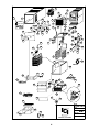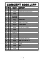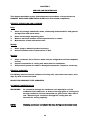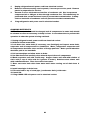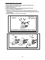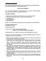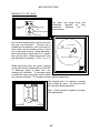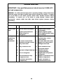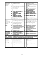
1
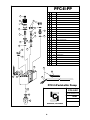
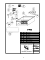
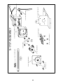
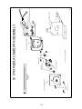
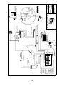
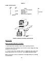
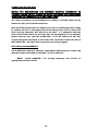
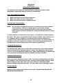
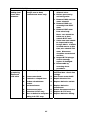
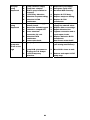
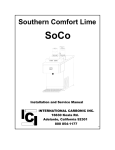
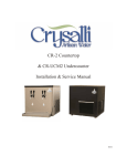
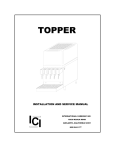
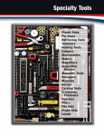
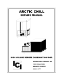
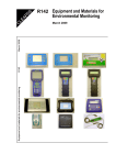
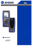
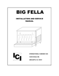
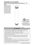
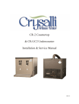
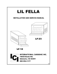
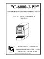
"C-6000-J-PP"
CONCEPT PERISTALTIC PUMP DISPENSER SYSTEM
INSTALLATON AND SERVICE
MANUAL
Chilled
Fruit Juices
ICI
INTERNATIONAL CARBONIC INC.
16630 KOALA RD., ADELANTO, CA 92301
(800) 854-1177 * FAX (760) 246-4044
"SODA-FAST SYSTEMS FOR EVERY APPLICATION AND USE"
IMPORTANT: This
manual
is
a
guide
for
installing,
operating, servicing and maintaining this equipment. Refer
to
Table
of
Contents
information
to
answer
installation,
operating,
for
page
location
of
that
arise
questions
service
installation of this equipment.
and
detailed
during
maintenance,
or
TABLE OF CONTENTS
PAGE
PREFACE .............................................................................................. 1
CHAPTER 1
GENERAL DESCRIPTION ..................................................................... 2
SYSTEM DESCRIPTION ....................................................................... 2
DESIGN DATA ...................................................................................... 3
THEORY OF OPERATION ..................................................................... 3
EXPLODED VIEW.................................................................................. 5
EXPLODED VIEW DESCRIPTION ......................................................... 6
EXPLODED VIEW DESCRIPTION, (Continued), .................................. 7
PFC-II-PP EXPLODED VIEW ................................................................. 8
PPM EXPLODED VIEW ......................................................................... 9
S-1737 ASSEMBLY ............................................................................... 10
S-1743 ASSEMBLY ............................................................................... 11
ELECTRICAL SCHEMATIC ................................................................... 12
CHAPTER II
UNPACKING AND INSPECTION........................................................... 13
SELECTING LOCATION........................................................................ 13
LOCATION RECOMMENDATIONS........................................................ 13
SAMPLE OF POSSIBLE INSTALLATION .............................................. 14
INSTALL WATER FILTER ASSY. .......................................................... 14
INSTALL WATER PRESSURE REGULATOR ......................................... 15
INSTALL DRAIN LINE .......................................................................... 15
INSTALL B.I.B. ..................................................................................... 15
CONNECTING WATER INLET............................................................... 16
ELECTRICAL REQUIREMENTS ............................................................ 16
CHAPTER III
PREPARING SYSTEM FOR OPERATION .............................................. 17
PREPARING AND STARTING REFRIGERATION UNIT......................... 17
PURGE DISPENSING VALVE................................................................ 17
ADJUST WATER FLOW RATE .............................................................. 17
ADJUST WATER TO SYRUP RATIO ..................................................... 17
CHAPTER IV
OPERATORS INSTRUCTIONS .............................................................. 18
DAILY PRE-OPERATION CHECK.......................................................... 18
COOLING UNIT MAINTENANCE .......................................................... 18
CHECKING WATER BATH .................................................................... 18
CHANGING WATER BATH.................................................................... 18
CLEANING NOZZLES ........................................................................... 18
CHAPTER V
SERVICE AND MAINTENANCE ............................................................ 19
PERIODIC INSPECTION AND CLEANING ............................................ 19
PERIODIC CLEANING........................................................................... 19
CLEANING CONDENSER COIL............................................................. 19
CHANGING WATER BATH.................................................................... 20
CHANGING PERISTALTIC PUMP TUBING........................................... 21
CLEANING AND SANITIZING............................................................... 22
BRIX INSTRUCTIONS .......................................................................... 24
BRIXING PROCEDURES ....................................................................... 25
TROUBLE SHOOTING .......................................................................... 26
NOTES .................................................................................................. 29
PREFACE
INTERNATIONAL CARBONIC INC. has enjoyed
over 53 years of manufacturing excellence in the
field of carbonation and in the beverage related
industry. We have been located in the Southern
California area since 1952 and have a long and
proud history with quality as our standard and
innovation as our goal. Originally started just
after World War II in Canfield Ohio as Carbonic
Dispensers we enjoyed patents on the first
Sodajet type carbonator.
This method of
carbonation instantaneously carbonated the
water to 100% saturation. We developed the
first patented dispensing valve to dispense bulk
beverage with carbonation equal to or in excess
of bottled beverages. A valve with three flavors
and soda was another first. We were the first to
incorporate the total post-mix package, i.e.,
carbonation, refrigeration & the ability to
dispense from one self contained unit. We have
pioneered many such firsts and will continue to
develop advance systems for the future, such as
electronic interrogatable portion controls to
electronic liquid level controls.
We hope you enjoy this product that has been
produced to give many years of trouble free
service. We thank you for your purchase and
hope we may serve you in the future.
1
C-6000-J-PP CHAPTER I
GENERAL DESCRIPTION
This chapter gives the description, theory of operation, and design data for the
CONCEPT 6000 JUICE PERISTALTIC PUMP unit, (C-6000-J-PP), and related
components.
SYSTEM DESCRIPTION
The C-6000-J-PP is a complete self-contained Juice unit which when combined with
B.I.B containers, will produce a variety of cooled non-carbonated beverages. The C6000-J-PP consists of a water bath, refrigeration system, valves, and modular
peristaltic pump compartment. The cabinet is housed in an attractive black vinyl or
stainless steel and the peristaltic pump module is housed in a rugged stainless steel
housing. The C-6000-J-PP has been designed to eliminate the use of bag in the box
pumps and associated components. The C-6000-J-PP will dispense product with
B.I.B.’s at a distance of 100 feet horizontally or 17 feet vertically.
THESE
DISTANCES ARE ONLY POSSIBLE IF THE SUPPLY LINE HAS COMPLETE INTEGRITY.
IF EVEN THE SMALLEST VACUUM LEAK IS ALLOWED THESE DISTANCES ARE NOT
POSSIBLE. The C-6000-J-PP can brix from one to one up to twenty to one by using a
state of the art controller/potentiometer adjustment.
For proper function the C-6000-J-PP must have a water supply, and electrical supply
and drainage. The C-6000-J-PP is designed with a unique lift off drain pan that can
be emptied at any convenient drain outlet.
WARNING: Before shipping or relocating a C-6000-J-PP into a
freezing ambient environment empty plain water. Syrup systems
should be flushed, ice bank melted, and water drained from
water bath. A freezing ambient environment will cause existing
water in unit to freeze possibly resulting in damage to water coil,
peristaltic pumps, water bath, valve(s), etc.
Water Filter Recommended (Optional) See Manufacturer Specifications for Operating
Conditions
2
DESIGN DATA
C-6000-J-PP
Overall Cabinet/P.P. Base dimensions:
Height
.................................................................................. 33”
Width
................................................................................... 17 3/4”
Depth
................................................................................... 30”
Weights:
Shipping ................................................................................... 190 pounds
Dry weight ................................................................................... 165 pounds
Operational Weight ..................................................................... 265 pounds
Capacities:
Unit water bath ........................................................................... 12 gallons
Refrigerant requirement (R-134a) ............................................... 10 3/4 ounces
................................................................................... 305 grams
Ambient operating temperature ................................................. 40 F to 100 F
Electrical Requirements:
The cooling unit requires a 115 VAC, single phase, 60 Hertz power circuit.
Circuit Ampacity ......................................................................... 9.3 Amps
Condensing Unit .......................................................................... 6.8 Amps
Agitator
................................................................................... 1 Amp
Peristaltic Pump Assembly @ 4 valves........................................ 1 Amp
Transformer................................................................................. .5 Amp
REFRIGERATION 1/3 H.P. capillary air-cooled.
THEORY OF OPERATION
The C-6000-J-PP was designed to manufacture and dispense non-carbonated
beverages much like your local bottling plant that cans or bottles your favorite
non-carbonated drink.
The water bath must be filled with approximately 12 gallons of water. After
all connections are made and activation of the refrigeration a certain amount
of this water will be transformed into ice, approximately 35 pounds. This
water reserve and ice bank will act as a reservoir for refrigeration. This
reserve is utilized during peak periods when the BTU output of the compressor
is not sufficient to meet the demand of the draw.
3
The incoming water is routed through a water coil that is submerged in the
above mentioned water bath. The temperature of the incoming water is at
ambient temperature as it enters the submerged water coil. As the incoming
water passes through the water coil the heat is removed from the water in the
water coil and chilled to a temperature acceptable for a quality drink,
normally a temperature of 33 to 34 degrees is reached. The water is now
directed to a valve where the water and syrup are mixed in proper proportions
to dispense a quality drink. Depending on the ratio of water versus syrup the
temperature will rise and be dispensed at approximately 40 degrees
fahrenheit.
With the incorporation of the peristaltic pump the necessity for an air or CO2
supply is no longer necessary, this includes the low and high-pressure
regulators normally needed for a standard juice unit. The peristaltic pumps
will pull the syrup concentrate from the B.I.B., (bag in the box), and then push
the syrup through syrup cooling coils, (optional), and then to the valve where
the syrup concentrate and water are mixed in a proper ratio to dispense a
quality drink. The syrup enters the C-6000-J-PP through a unique 1/4” X 3/8 S162 bulkhead fitting at the rear of the unit.
The water source should be regulated, this is normally performed by the use of
an in line water regulator. If the water is not regulated and the water
pressure can vary. This variance of water pressure can effect our dispensed
product.
4
3
5
4
Chilled
Fruit Juices
1
2
24
25
Chilled
23
Fruit Juices
15
8
21 22
20
9
29
19
26
15
27
11
10
12
28
13
31
5
11
34 33
32
36
35
16
37
38
44
43
14
15
30
42
7
6
40
15
41
18
45
39
17
47
46
48
51
49
52
57
50
55
54
53
56
58
59
60
61
63
31
62
34
64
INTERNATIONAL CARBONIC INC.
ICI
65
60
66
67
ADELANTO, CALIFORNIA
5
TITLE
C-6000-J-PP-SS
DATE
12/15/04
DRN. BY
CHK. BY
APPR. BY
GLW
CONCEPT 6000-J-PP
SYM QTY
1
1
2
1
3
1
4
1
5
2
6
4
7
1
8
9
10
11
12
13
14
15
16
17
18
19
20
21
22
23
24
25
26
27
28
29
30
31
32
33
1
1
1
4
1
1
1
6
1
1
1
1
2
1
1
1
4
1
2
2
1
1
1
8
1
1
PART NO.
S0985-J
S1216
S1291
S0192-Y
S1276
A0024
AEA3440YXAXL
DESCRIPTION
PANEL, JUICE
COVER ONLY
REFRIGERATION SYSTEM COMPLETE
REFRIGERANT DRIER, R-134
OFFSET HANDLE 5"
10-24 X 3/8 T.H., SCREW
CONDENSING UNIT, 1/3 H.P. W/DRIER
AEA3440YXA
COMPRESSOR, 1/3 H.P. W/DRIER
S1470
S1277
S1275
A0026
S1281
S0513-A
S1304-U
A0020
Z0008
S0409
S1283
S1224-110
S0973
E0665
S1228
S0952
G0010
S1229
A0009
A0060
S0955
S0958
S0956
A0014
S1700
S0766
HANDLE
SUPPORT HINGE
HANDLE BRACKET
SCREW, 1/4-20 X 1/2 HEX
CONDENSER BASE W/EVAP SPACERS
ICE BANK CONTROL
ICE BANK BULB BRACKET, UNIVERSAL
8-32 X 3/8 T.H., S.S. SCREW
CAP TUBE, 12' - 1/8
9" ACCUMULATOR
EVAPORATOR COIL ASSY
BASE, ILLUMINATION
LAMP HOLDER
STRAIN RELIEF
LAMP HOLDER BOX W/COVER
BALLAST
WIRE TERMINAL, SMALL BELL
LAMP HOLDER BOX COVER ONLY
SCREW, 8 X 3/8" PHIL P.H. "A"
SCREW, 6-32 X 1/4, FLAT HEAD
STARTER
STARTER HOLDER
LAMP
SCREW, #10 X 1/2" PHIL HD, S.S.
TRANSFORMER, 100 VA
UNIT ON/OFF SWITCH
6
SYM QTY
34
8
35
4
36
1
37
1
38
1
39
1
40
3
41
1
42
2
43
1
44
1
45
1
46
1
47
1
48
1
49
1
50
6
51
1
52
2
53
1
54
12
55
12
56
4
57
7
58
7
59
6
60 1 SET
61
6
62
1
63
1
64
1
65
1
66
1
67
1
CONCEPT 6000-J-PP CONTINUED
PART NO. DESCRIPTION
SQUARE GROMMET NUT
S1325
TERMINAL BOARD SPACER, NYLON, 3/8"
S1335
SNAP IN RECEPTACLE
S1244
CONTROL BOX WITH COVER
S1279
TERMINAL BOARD
S1309
STRAIN RELIEF
E0664
BUSHING
S0046
CONTROL BOX COVER ONLY
S1280
#8 X 1/2 SELF TAPPING SCREW
F0004
S0835-L AG1TATOR
S1270-LG AGITATOR BRACKET
WATER COIL, JUICE
S1278
STANDPIPE, 13 1/4"
S1285
E0141-12 POWER CORD, 12'
WRAPPER & BUCKET ASSY W/INSULATION
S1217
VALVE HOUSING
S1225
VALVE SWITCH
S1313
SWITCHLOCK W/KEYS
S1330
S1330-K SWITCHLOCK KEYS
S1219-6 VALVE MOUNTING PLATE
"C" PLASTIC CLAMP
S1698
S0138-L SPLICER, 1/4" HOSE EL
5/16 X 18 X 1/2 HEX HD BOLT
A0045
1/4H X 3/8H SS W/HEX BODY BULK HD FITTING
S0162
S0286-A JAM NUT S.S.
PERISTALTIC PUMP ASSEMBLY
S1737
DRAIN PAN HARDWARE, SET
S0743
PFC-II-PP DISPENSING VALVES, PERISTALTIC PUMP
S1220-6 BASE ASSY, PERESTALTIC
COVER, BASE ASSY, PERESTALTIC
S1221
CUP REST
S1223
DRAIN PAN W/CUP REST
S1222
PLASTIC DRAIN ASSY, 90 - 1/2
S1164
S1166-A PLUG FOR S-1164 DRAIN ASSY
7
PFC-II-PP
SYM QTY
1
2
3
6
4
8
7
5
9
10
12
11
PART NO.
DESCRIPTION
1
1
E-623
NUT, SOLENOID
2
1
E-525
COIL, W/SHIELD, SOLENOID, 24 VAC
3
4
E-1005
SCREW, RETAINER
4
1
E-739
FLUX PLATE
5
1
E-527
STEM, SOLENOID VALVE
6
2
E-1004
RETAINER, S.S.
7
1
E-135
8
1
E-1024-M
METERING PIN
ADAPTER, FLO WASHER, MODIFIED
9
1
E-134
"O" RING, METERING PIN
10
1
E-1013
"O" RING, SYRUP ADAPTOR
11
1
E-730
PLUNGER & SPRING ASSEMBLY
12
1
E-520
METERING PIN ADAPTOR ASSY, INCLUDES SYM 7,9, & 12
13
2
E-531
GASKET, SOLENOID STEM
14
1
S-1162-A
15
1
E-1008
FLANGE PLUG
"O" RING, SODA ADAPTOR
13
14
15
13
16
16
1
E-580
BODY, PFC-II, TWIST LOCK
17
1
E-157
SUBMINIATURE SWITCH
18
1
E-188
19
1
E-471-FF
SPRING AND INSULATOR PAD
SYRUP OUTLET TUBE
20
1
E-102
"O" RING, NOZZLE
21
1
E-581
NOZZLE, TWIST LOCK
22
1
E-690
WIRE ASSEMBLY CONSISTS OF E-691 & E-692
23
1
E-691
MALE WIRE ASSEMBLY ONLY
24
1
E-692
FEMALE WIRE ASSEMBLY ONLY
22
23
17
18
24
PFC-II-Peristaltic Pump
INTERNATIONAL CARBONIC INC.
19
ICI
20
21
ADELANTO, CALIFORNIA
8
TITLE
PFC-II-PP
DATE
2/27/01 REVISED 9/27/01
DRN. BY
CHK. BY
APPR. BY
GLW
1
2
4
3
6
5
8
7
9
10
11
12
PPM
13
SYM QTY PART NO.
DESCRIPTION
1
2*
S1698
PLASTIC CLAMP
2
1
S1700
TRANSFORMER
3
1*
S1737
P.P. ASSEMBLY
4
1*
S0162
BULK HEAD FITTING
5
1*
S1699
POTENTIOMETER
6
1*
S1741
CONTROLLER
7
4*
S1335
PLASTIC STANDOFF
8
1 **
**
BASE, MODULE
9
1*
S0286-A NUT, SS, LOCKING, 1/2" X 20 (USEW/S-162)
10
1*
S1742
BASE, PUMP
11
1*
S1325
SQUARE GROMMET NUT
12
1*
A0014
SCREW #10 X 1/2" PHILLIPS HD S.S.
13
1 **
**
COVER, MODULE BASE
*PER FLAVOR, SPECIFY NUMBER
** = SPECIFY NUMBER/MODEL TYPE
INTERNATIONAL CARBONIC INC.
IC
I
ADELANTO, CALIFORNIA
9
TITLE
Peristaltic
Module
DATE
8/14/00
DRN BY
CHK BY
APPR. BY
GLW
10
6-32 X 3/4 PH S.S.
S-1739-C HOUSING/COVER
.250 X .437
NEOPRENE
S-1722
S-1741 - CONTROLLER
S-1739-H PUMP HOUSING BODY
S-1335 - PLASTIC STANDOFF
PLASTIC
WASHER
8-32 X 3/8" PH S.S.
S-1740 - ROLLER ASSY.
S-1698 - PLASTIC CLAMP
S-1737 ASSEMBLY
S-1742 - SHEET METAL BASE
S-1699 - POTENTIOMETER
S-1738 - MOTOR/GEAR BOX ASSY.
11
6-32 X 3/4 PH S.S.
S-1739-C HOUSING/COVER
MITYFLEX
NOR-6F-250
S-1722
S-1335 - PLASTIC STANDOFF
S-1740 - ROLLER ASSY.
PLASTIC
WASHER
8-32 X 3/8" PH S.S.
S-1739-H PUMP HOUSING BODY
8/01
S-1738 - MOTOR/GEAR BOX ASSY.
S-1742 - SHEET METAL BASE
S-1743 REPLACEMENT ASSEMBLY
12
BLACK
TERMINALS
ON ROW C
MUST BE
COMMONLY
GROUNDED
TO CABINET
WHITE
GROUND
SCREW
110 VOLT
D
C
B
A
1
1
1
1
2
2
2
2
3
3
3
3
4
4
4
4
5
5
5
5
6
6
6
6
ICE BANK
CONTROL
BLACK
ON/OFF SWITCH
TRANSFORMER
110 VAC
WHITE
THREE PIN CONNECTOR
TO VALVE
TRANSFORMER
24 VAC
NON-RIBBED
KEY SWITCH
RIBBED
COLORED
CONDENSING UNIT
BROWN
BLUE
COLORED
1
ICI
FROM VALVE
NON-RIBBED
COLORED
3
S
M
ADELANTO, CALIFORNIA
R
NC
NO
C
COMPRESSOR
APPR. BY
CHK. BY
GLW
GLW
G.L. WHEELER
10/3/05
PPM
ELECTRICAL
SCHEMATIC
DRN. BY
DATE
TITLE
BLACK FROM
COIL
BLACK FROM
COIL
WATER COIL
BLACK
RIBBED
1
C
INTERNATIONAL CARBONIC INC.
AGITATOR MOTOR
POTENTIOMETER
ORANGE
WHITE
BLUE
NON-RIBBED
RIBBED
WHITE
S
FAN MOTOR
CHAPTER II
INSTALLATION
C-6000-J-PP
This chapter covers unpacking and inspection, selecting location, installing
CONCEPT 6000 JUICE PERISTALTIC PUMP unit, C-6000-J-PP and related
components, and electrical requirements.
UNPACKING AND INSPECTION
Upon receiving unit, immediately remove C-6000-J-PP from shipping carton and
inspect for shipping damage.
NOTE:
Before leaving the factory the Concept 6000 Juice Peristaltic Pump
unit was carefully inspected and the carrier has accepted and signed
for it. Any damage or irregularities should be noted at the time of
delivery and immediately reported to delivering carrier. Request a
written inspection report from claims inspector to substantiate any
necessary claim. File claim with delivering agency, not International
Carbonic Inc!
SELECTING LOCATION
IMPORTANT:
Ambient temperature for cooling unit should not exceed
100 degrees “F". Operation of cooling unit in ambient
above 100 degrees “F" can and will contribute to early
failure of condensing unit and poor quality of finished
product.
LOCATION RECOMMENDATIONS FOR C-6000 JUICE PERISTALTIC PUMP unit, C-6000J-PP
1.
2.
3.
4.
5.
Position unit as close as possible to proper electrical source, 115V 6OHz.
Position unit with a minimum of 2" space between bulkhead and cabinet for
sufficient space for ventilation. Allow enough space between ceiling and unit
for lid removal.
Position unit as close as possible to floor drain.
Position unit as close as possible to B.I.B. racks.
Position unit as close as possible to water source. Half inch gate valve
recommended for water connection.
13
TABLE 2-1
LOOSE - SHIPPED PARTS
Item
Part
No.
No.
1
2
S-1149
3
----4*
5*
S-208A
*
Optional
Name
Installation/Service Manual
Drain pan
Product Decals
Water filter
Water Pressure Regulator
Qty
1
1
1 per flavor
1
1
Chilled
Fruit Juices
FIGURE 2 SAMPLE OF POSSIBLE INSTALLATION.
INSTALLATION
INSTALL WATER FILTER ASSY. (OPTIONAL)
1. Install water filter assembly on wall or other supporting structure.
2. Connect water filter assembly to inlet of valve on water supply line using
minimum 3/8" I.D. water line.
3. Connect water filter assembly outlet to C-6000-J-PP plain water inlet
fitting using minimum 3/8" I.D. water line. See CONNECTING WATER INLET.
When a water filter is used, it is important to thoroughly flush prior to making
unit connections.
14
INSTALL WATER PRESSURE REGULATOR (OPTIONAL)
If water pressure varies, a water pressure regulator or water pressurereducing valve should be installed in the water supply line. The water
regulator must have an orifice of at least 3/16” so as not to restrict the water
flow through the valve. Valves that are built with 1/2" pipe thread connection
usually have a sufficient orifice opening.
WATER REGULATOR
1/2" GATE VALVE
WATER FILTER
FIGURE 2-4. SUGGESTED WATER FLOW INSTALLATION
INSTALL DRAIN LINE
1. Connect drain line on C-6000-J-PP unit with drain using 1/2” I.D. clear
plastic tubing to nearest outlet.
2. Do not reduce drain connection from cabinet outlet.
3. Be sure all connections are water-tight.
INSTALL B.I.B.
1. Place B.I.B. as close as possible to C-6000-J-PP unit, preferably no farther than 15
feet. The C-6000-J-PP will dispense product with the B.I.B.’s at a distance of 100
feet horizontally or 17 feet vertically. THESE DISTANCES ARE ONLY POSSIBLE IF
THE SUPPLY LINE HAS COMPLETE INTEGRITY. IF EVEN THE SMALLEST VACUUM
LEAK IS ALLOWED THESE DISTANCES ARE NOT POSSIBLE.
2. Lay out syrup lines from unit to B.I.B.
3. Connect lines from B.I.B. to inlet on C-6000-J-PP.
4. Activate Q.C.D.
5. Check all connections for leaks, (see Chapter IV).
15
CONNECTING WATER INLET
WATER PIPE CONNECTIONS AND FIXTURES DIRECTLY CONNECTED TO
POTABLE WATER SUPPLY SHALL BE SIZED, INSTALLED AND MAINTAINED
ACCORDING TO FEDERAL, STATE, AND LOCAL LAWS.
The water connection on the C-6000-J-PP is made to a flexible water line by
means of a 3/8”, hose or barb connection.
After all primary water lines are made up, but prior to connecting water supply
to cabinet, be sure to thoroughly flush all incoming water lines to remove all
scale and any impurities that may be in the lines. It is imperative that the
fresh water-conduit have not less than 3/8” I.D. passageway for any distance
greater than ten feet from the C-6000-J-PP. It can be reduced to 3/8” O.D.
copper tubing and connected to the water inlet connection with-in ten feet of
the C-6000-J-PP. All water inlet connections are clearly tagged.
ELECTRICAL REQUIREMENTS:
The C-6000-J-PP requires a 120 VAC, single phase, 60 Hertz power circuit, and
must be wired in accordance with N.E.C. or local ordinance.
NOTE:
Check CHAPTER I for running amperage and connect to
appropriate electrical circuit.
16
CHAPTER III
C-6000-J-PP
PREPARATION
All steps in previous chapters should be understood and carried out before
proceeding.
PREPARING SYSTEM FOR OPERATION
Be sure that electrical power is unplugged, and valve on water supply line is
closed.
PREPARING AND STARTING REFRIGERATION UNIT
1. C-6000-J-PP refrigeration is pre-set at factory and ready to operate.
2. Remove lid.
3. Fill water bath with clean water until water runs out of condensate drain
outlet, (S-657), (approximately ½” from top of water bath).
4. Open water inlet supply line.
5. Plug C-6000-J-PP power cord into electrical receptacle box, turn power
switch to the "ON" position. Make sure compressor, condenser fan motor,
agitator motor start. The process of cooling the water bath will commence
after filling water bath. With ambient and water temperature of 75 degree “F”
initial pull down or formation of complete ice bank will take approximately 4.5
hrs. When full ice bank has been formed, compressor and condenser fan
motor will stop. Agitator will continue to operate, circulating water in water
bath.
PURGE DISPENSING VALVES
Dispense water from dispensing valves until all air is purged from water lines.
ADJUST WATER FLOW RATE
Adjust dispensing valves water flow rate to approximately 6 oz. in 5 seconds.
ADJUST WATER-TO-SYRUP "RATIO"
Adjust dispensing valves for Water-to-syrup "Ratio".
concentrate for recommended ratio.
17
Contact supplier of syrup
CHAPTER IV
C-6000-J-PP
OPERATORS INSTRUCTIONS
This chapter covers operators’ responsibilities for daily pre-operation check,
adjustments, replenishing C02 and cleaning, and sanitizing.
DAILY PRE-OPERATION CHECK
1.
2.
3.
Make sure B.I.B.’s full and ready to dispense.
Make sure nozzles are clean and in place.
Make sure electrical power is supplied to unit.
COOLING UNIT MAINTENANCE
NOTE:
Air circulation through the condenser coil required to cool the condenser
coil/compressor, is drawn in through grills on cooling unit, through
condenser coil and is exhausted out grills on the other side of the unit.
Restricting air circulation through the cooling unit will decrease its cooling
capacity.
To avoid needless and sometimes costly repairs, it is imperative to keep condenser
fins clean. This may be accomplished by one of three methods. One method is use
of a condenser brush (a longhaired, soft bristle brush) to gently sweep fins of
condenser clean. Second method is to use a strong vacuum. The third method is to
use C02 or an air hose to blow out condenser. The latter method should only be
attempted after normal business hours to avoid dust contamination.
CHECKING WATER BATH
Periodically check water level in water bath. If water level is low, water should be
added as instructed for maximum product cooling. This dehydration will normally
not occur in normal temperate climate zones. With normal humidity the opposite will
occur therefore it is paramount that the condensate drain be installed.
CHANGING WATER BATH
Drain water bath a minimum of twice a year. This can be accomplished by locating
the standpipe in the water bath area and removing by twisting and pulling up. Once
water is drained, water bath, water coils, bath walls, etc. should be cleaned.
Replace standpipe and refill with water. Fill water bath to top of standpipe, (S-657).
CLEAN NOZZLES
Remove nozzles nightly and let soak in warm water. DO NOT SOAK IN HOT HOT
WATER OR BLEACH WATER!
18
CHAPTER V
SERVICE AND MAINTENANCE
This chapter describes service and maintenance procedures to be performed on
CONCEPT 6000 JUICE PERISTALTIC PUMP units and related components.
PERIODIC INSPECTION AND CLEANING
Daily:
1.
2.
3.
4.
Clean any storage tanks/B.I.B. racks, connecting sockets/Q.C.D.’s and general
storage area with warm water.
Clean the beverage dispensing area.
Remove and clean nozzles and all exposed areas on valves.
Wipe exterior of unit with moist towel.
Weekly:
1.
2.
Order syrup to maintain product inventory.
Check condenser coil for obstructions or dirt.
Monthly:
1.
2.
3.
Clean condenser fins or filter to make sure the refrigeration unit has adequate
air flow.
Inspect components of cooling unit water bath for cleanliness.
Check entire system for leaks or damaged components. Repair as necessary.
PERIODIC CLEANING
Periodically wash all external surfaces of cooling unit, rinse with clean water, then
wipe dry with a clean soft cloth.
DO NOT USE ABRASIVE TYPE CLEANERS.
CLEANING CONDENSER COIL
IMPORTANT:
Air circulation through the condenser coil required to cool the
condenser coil/compressor, is drawn in through grills on cooling unit,
through condenser coil and exhausted out grills on the other side of
unit. Restricting air circulation through the cooling unit will
decrease its cooling capacity.
NOTE:
Cleaning condenser coil should be done during non-business hours
19
1.
2.
3.
4.
Unplug refrigeration unit power cord from electrical socket.
Remove 6 screws securing service panels, 2 screws per service panel. Remove
panels in preparation for service.
Vacuum or use a soft brush to clean fins of condenser coil. Use low-pressure
compressed air or C02 gas to blow through condenser fins. This should only be
performed after normal business hours to prevent dust contamination. A damp
cloth on back-side of condenser coil will prevent some dust contamination.
Plug refrigeration unit power cord in electrical socket.
CHANGING WATER BATH
NOTE: The water bath should be changed and all components in water bath should
be cleaned as often as necessary to keep it clean. A convenient time to perform this
operation is when the system is being sanitized.
1. Unplug refrigeration unit power cord from electrical socket.
2. Remove lid from water bath.
3. Look down into water bath (if necessary, use flashlight) and inspect water bath,
evaporator and all components for cleanliness. Water, refrigeration evaporator and
all components should be clear and free of foreign particles. Note: special attention
should be paid to ice bank bulb.
4. Pull out standpipe and allow water to drain.
S. Use fiber brush and carefully clean mineral deposit from all components.
6. Wash evaporator coil with a mild soap. Copper cleans well with mild solution of
citric acid (1 cup of citric acid for 2 gallons of water). Stainless steel cleans well
with carbonated water. Then rinse with clean water.
7. Rinse out water bath with clean water until water running out of drain hose is
clean.
8. Install stand-pipe in drain hose.
9. Fill water bath to top of stand pipe, (condensate drain), with water.
10. Install lid.
11. Plug C-6000-J-PP unit power cord in electrical socket.
20
CHANGING PERISTALTIC PUMP TUBING
Remove #10 X 1/2” Phillips TH. Screw. Then slide out S-1027 Assy.
Remove three 6-32 x 3/4 PH screws.
Remove S-1739 cover.
Remove neoprene tubing by pulling tubing while turn S-1740 roller.
Replace old neoprene tubing with new.
Squeeze new tubing with pliers two insert tubing in between first roller and
housing wall. Force tubing into position at second roller by spinning roller while
inserting tubing.
7. Reverse procedure to reinstall S-1737 assembly.
1.
2.
3.
4.
5.
6.
OUTLET
TO VALVE
INLET
COUNTER CLOCKWISE ROTATION
S-1698
PLASTIC
CLAMP
S-1698
PLASTIC
CLAMP
.250 X .427
NEOPRENE
TUBING
S-1737
ASSY.
S-1739
6-32 X 3/4 PH
SS SCREW
S-1740
ROLLER
21
CLEANING AND SANITIZING
Your local Health Department rules and general area cleanliness should determine
the frequency of which the unit should be sanitized.
SANITIZING PROCEDURES
Your local health department rules and general area cleanliness should determine
the frequency at which the unit should be sanitized.
EQUIPMENT REQUIRED:
1.
2.
3.
4.
1.
Stainless Steel containers (product tanks), or large volume container.
CO2 Supply If applicable (Same as used with dispensing unit).
Cleaning Agent.
Sanitizing Solution.
Phenolphthalein.
NOTE: One recommended cleaning agent and sanitizing agent is manufactured by:
MT. HOOD CHEMICAL CORP.
4444 N.W. Yeon Avenue
Portland, Oregon 97210
Trade names are: STAR - CHLORINATED CLEANER
CROWN - 12.5% SODIUM HYPOCHLORITE BLEACH
Use STAR at 18 oz. per 1 gallon of water yields 2% Sodium Hydroxide Solution.
Use Crown at 2 ounce per 9 gallons of water (gives 200 PPM of available chlorine) at
a minimum contact time of 10 minutes.
1. Disconnect syrup containers and remove product from tubing by purging with
carbon dioxide or flushing with warm water.
2. Visually inspect valve by removing nozzle and inspecting nozzle and valve cavity.
Clean nozzle with cleaning agent, then sanitizing solution, then with potable
water. Inspect valve cavity and if dirty clean with soft bristle brush. Clean
exteriors of valve with a soft clothe and warm water. Replace valve nozzle then
go to step #3.
3. Fill syrup lines with a caustic-based (low sudsing, non-perfumed, and rinsed)
detergent solution, (STAR). The solution should be prepared in accordance with
the manufacturers recommendations, but should be at least 2 percent sodium
hydroxide. Make sure the syrup lines are completely filled and allow standing for
at least 10 minutes.
4. Flush the detergent solution from the syrup lines with clean water. Continue
rinsing until testing with phenolphthalein shows that the rinse water is free of
residual detergent.
5. Fill the syrup lines with a low PH (7.0) chloride solution containing maximum 200PPM chlorine. Make sure that lines are completely filled and allow standing for
30 minutes.
22
6. Reconnect syrup containers and ready Unit for operation.
7. A Draw drinks to refill syrup lines and flush the chloride solution from the
dispenser.
8. Taste the beverage to verify that there is no off taste.
NOTE: WHEN SANITIZING A TWO FLAVOR VALVE BOTH SYRUPS SHOULD BE
FLUSHED SIMUTAINEOUSLY, BOTH SYRUPS SHOULD BE CLEANED, (DETERGENT
SOLUTION), SIMUTAINEOUSLY, BOTH SYRUPS SHOULD BE FLUSHED UNTIL FREE
OF DETERGENT SIMUTAINEOUSLY AND BOTH SYRUPS SHOULD BE SANITIZED
SIMUTAINEOUSLY.
23
BRIX INSTRUCTIONS
BRIXING PFC-II-PP VALVE
Decrease
Water Metering
Pin
The water and syrup flows are
individually
adjusted
by
their
respective
metering
pin
/
potentiometer.
Syrup Metering Pin
Plug
Water Solenoid Assembly
Front
Syrup Plug
One recommended method utilizes the ratio
brix cup, see illustration. The brix cup is
divided into two sections, one to hold up to 9
parts water and the smaller section to hold
one or two parts of syrup. When adjusting a
flavor with a ratio of more than 9 to 1 syrup 2
line must be used. When using syrup 2 line
the waterside is doubled to 18 to 1 vs. 9 to
1.
POTENTIOMETER
CLOCKWISE TO INCREASE
COUNTERCLOCKWISE TO DECREASE
When facing the valve, the syrup is always
to the right and the water/soda is to the left.
To decrease syrup or water flow, turn
metering pin clockwise. To decrease syrup
or water flow, when using flow control valves
turn counter-clockwise. To increase, reverse rotation respectively.
The ultimate goal is to achieve a proper
ratio of water vs. syrup. This ratio can and
will vary with differing products.
Note: Contact product supplier for proper
ratio adjustments.
Up to 18 Parts
One part
24
TROUBLE SHOOTING
IMPORTANT: Only qualified personnel should service C-6000-J-PP
unit and components.
WARNING: To avoid personal injury and or property damage, always disconnect
electrical power and shut off plain water before starting any repairs. If repairs
are to be made to the water system, bleed water system pressure before
proceeding.
If repairs are to be made to syrup system, remove quickdisconnects, remove QCD from BIB, then bleed system pressure before
proceeding.
COOLING UNIT
Trouble
Probable Cause
Remedy
Frozen water
bath
1.
Bad ice bank control/bulb.
1.
2.
3.
2.
3.
Cooling or
condensing
unit nonoperational
1.
Agitator pump defective
Under charge on
refrigerant.
No electrical power.
1.
2.
3.
4.
No water in water bath.
Defective ice bank control.
Dirty water bath.
2.
3.
4.
5.
Dirty condenser unit.
5.
6.
Improper voltage/amperage
6.
7.
Loss of refrigerant.
7.
8.
Bad overload and relay.
Compressor bad.
Restriction (pinched or
crimped line).
8.
25
Replace bad ice bank
control/bulb.
Replace Agitator pump.
Find refrigerant leak, repair
and recharge.
Plug power cord into
electrical box. Check
on/off switch.
Fill water bath with water.
Replace ice bank control.
Change water bath.
Clean condenser unit
w/vacuum cleaner.
Check for proper
voltage/amperage.
Repair leak and replenish
refrigerant.
Replace overload and relay
Replace compressor.
Repair, straighten or
replace defective line.
Compressor
does not
operate
1.
No power source.
1.
2.
Electrical power to cooling
unit turned off.
Low voltage.
2.
Loose, disconnected, or
broken wire.
Inoperative ice bank
control.
Inoperative overload
protector or start relay.
Inoperative compressor.
Full ice bank.
Cooling capacity is
exceeded by over drawing.
4.
3.
4.
5.
6.
Compressor
works
continuously
but does not
form ice
bank.
7.
8.
1.
2.
3.
4.
5.
Plug power cord to
electrical box. Check line
voltage.
Turn on power switch to
unit.
Voltage must be at least
110 V at compressor
terminals at start.
Tighten connection or
replace broken wiring.
Replace ice bank control.
6.
Replace defective part.
7.
8.
1.
Replace compressor.
Refrigeration not called for.
Reduce amount of drinks
taken per given time of
install higher voluum unit.
Relocate cooling unit.
3.
Cooling unit located in
2.
excessively hot area.
Air circulation through
3.
condenser coil is restricted
Loss of refrigerant or in4.
sufficient charge.
Check and if necessary,
clean condenser coil.
Repair leak and/or
recharge with sufficient
refrigerant.
Clean water bath.
Replace ice bank control.
Dirty water bath.
5.
Compressor
Ice bank control capillary
1.
will not stop
tube kinked or broken.
after forming 2. Ice bank control stuck in
2. Replace ice bank control.
ice bank
closed position.
Note: During overload protector shut off condenser fan motor will continue to
work. Otherwise, troubleshooting condenser fan motor problems is the same as
“Compressor does not operate”, paragraph in addition to the following.
Condenser
1. Electrical cord loose or
1. Tighten connections or
fan motor
disconnected from
replace cord.
not
condenser fan motor or
operating
compressor terminals.
2. Fan blade obstructed.
2. Remove obstruction.
3. Inoperative condenser fan
3. Replace condenser fan
motor.
motor.
5.
1.
26
DISPENSING VALVES
Water
1. Foreign debris under
leaking from
plunger seat or bent,
nozzle after
creased stem water only.
actuation
No water, no
syrup being
dispensed
from valve
1.
1.
No electrical power.
1.
2.
3.
4.
Frozen water bath.
Pinched or crimped lines.
Broken sub-miniature
switch.
Bad transformer.
2.
3.
4.
Disconnected wire.
Defective S-1737 assy.
Worn or defective neoprene
tubing in S-1737 assy.
6.
7.
8.
5.
6.
7.
8.
27
5.
a. Disconnect water from
affected valve.
b. Relieve pressure by
activating valve.
c. Remove E-623 nut from
water solenoid.
d. Remove E-525 coil
assembly from E-527
stem.
e. Remove E-527 stem
from valve body.
Note: care should be
taken not to dent
smooth E-527 wall.
f. Valve stem seat should
be inspected for any
foreign debris. If debris
is found remove at this
time, also check E-730
stem. Movement
should be unrestricted
and free.
g. Inspect E-730 plunger
seat for damage,
replace if damaged.
h. Reassemble by
reversing above
procedure.
Plug power cord into
electrical box. Check line
voltage.
See “Frozen water bath”.
Repair defective line.
Replace defective switch.
Replace defective
transformer.
Attach disconnected wire.
Replace S-1737 assy.
Replace defective tubing.
No syrup
being
dispensed
1.
2.
3.
4.
5.
6.
No water
being
dispensed
1.
2.
3.
4.
5.
Water-tosyrup ratio
to low or too
high
6.
1.
2.
3.
Syrup container empty.
Syrup lines crimped.
QCD of syrup installed incorrectly.
S-1737 Assy defective.
Defective neoprene tubing.
Defective S-1700
transformer.
Plain water inlet supply
shutoff closed.
Water filter fouled/clogged.
Pinched or crimped line.
Loose electrical
connection, 24 volt.
Defective E-276
transformer.
Frozen water bath.
Syrup adjusted to low.
Syrup B.I.B. placement to
far away for P.P. Pumps.
S-1737 Pump assy
defective.
28
1.
2.
3.
Replenish syrup supply.
Straighten syrup lines.
Re-install QCD correctly.
4.
5.
6.
Replace S-1737 Assy.
Replace neoprene tubing.
Replace S-1700
transformer.
Open plain water inlet
supply line shut off valve.
Replace filter or cartridge.
Repair defective line.
Tighten connection and or
repair open circuit.
Replace defective E-276
transformer.
See “Frozen water bath”.
Adjust water-to-syrup ratio
(see brixing instructions).
1.
2.
3.
4.
5.
1.
2.
Move B.I.B. closer to unit.
3.
Remove and repair S-1737
pump assy.
NOTE SECTION
Frequently Called Numbers:
__________________________________
____________________________
__________________________________
____________________________
__________________________________
____________________________
__________________________________
____________________________
__________________________________
____________________________
__________________________________
____________________________
CO2 SETTINGS:
High Pressure ________________________ PSI
Low Pressure ________________________ PSI
Product Setup:
#1
#2
_____________________________________
__________________________________
_____________________________________________________________________________________________
_____________________________________________________________________________________________
_____________________________________________________________________________________________
_____________________________________________________________________________________________
_____________________________________________________________________________________________
___________________________________________________
_____________________________________________________________________________________________
_____________________________________________________________________________________________
_____________________________________________________________________________________________
_____________________________________________________________________________________________
_____________________________________________________________________________________________
___________________________________________________
29