1
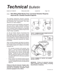
Troubleshooting Guide
Fuller Heavy Duty Transmissions
TRTS0902
October 2007
Table of Contents
Description
The Rear Mount Multi-Speed PTO Neutral Interlock System ........................................................................................... 1
Unit Identification
Model and Serial Number Identification .......................................................................................................................... 2
Installation
Introduction .................................................................................................................................................................... 3
Precautions ..................................................................................................................................................................... 5
Assembly and Installation of Parts for Modification ........................................................................................................ 6
Shift Lever and System Checklist .................................................................................................................................... 12
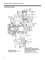
Sectional Views and Reference Charts
Models with a Two-Speed Auxiliary Section .................................................................................................................... 13
Deep Reduction Models .................................................................................................................................................. 14
13-Speed Splitter Models ................................................................................................................................................ 15
Sectional Views ............................................................................................................................................................... 16
Air System Schematics
Splitter Shift Auxiliary Models ......................................................................................................................................... 18
From Stationary to Mobile Position ................................................................................................................................. 20
From Stationary to Mobile Position ................................................................................................................................. 23
Troubleshooting
Forward ........................................................................................................................................................................... 27
Description
The Rear Mount Multi-Speed PTO Neutral Interlock System
The Fuller® Rear Mount Multi-Speed PTO Neutral Interlock System is designed to provide a neutral position in the auxiliary section of a Fuller Roadranger® Transmission (except RT-6610/6613 Series) for the purpose of using an Extended Rear Countershaft Power Take-Off (PTO) in a stationary vehicle mode. A locking mechanism, which is interlocked to the neutral position of the
unit’s front section, ensures that the AUXILIARY SECTION CANNOT BE RE-ENGAGED TO AN IN-GEAR POSITION UNLESS THE
FRONT SECTION IS IN NEUTRAL. This feature prevents accidental or inadvertent transmission operation which could result in
the vehicle moving under power.
The standard range cylinder assembly is modified to include a positioning piston and neutral plunger with mating ramps, for stationary mode operation. The air shut-off valve of this neutral/range cylinder assembly renders the shifting controls in the cab
inoperable when the neutral plunger is DOWN, locking the range yoke bar in the centered position during stationary mode operation. Even in the event that air to the range system is accidentally restored, an air line becomes severed, or other malfunctions of
the system occur, the auxiliary section will remain in neutral. Once the neutral plunger is down and locked in the neutral position,
the only way it can be overcome is with a “MOBILE” air signal sent from the stationary/mobile control valve and directed through
the sequencing protection valve.
The proven design of the Fuller Rear Mount Multi-Speed PTO Neutral Interlock System simplifies the procedure of engaging and
disengaging an extended rear countershaft PTO while providing the operator with the additional safety afforded by the neutral/
range cylinder when in the stationary mode.
CAUTION: FOR ANY STATIONARY VEHICLE OPERATION OF AN EXTENDED REAR COUNTERSHAFT PTO, A FULLER
NEUTRAL INTERLOCK SYSTEM IS REQUIRED.
For information, contact:
1
Eaton Corporation Transmission Division
North American Headquarters
Application Engineering Dept.
P.O. Box 4013
Kalamazoo, Michigan 49003
(269) 342-3000
Unit Identification
Model and Serial Number Identification
All Fuller Transmissions are identified by model and serial number. This information is stamped on the transmission identification
tag and permanently affixed to the case. For a detailed explanation of the model designations, refer to your Fuller Service Manual
(or equivalent).
Rear-Mounted PTO System Identification
Easy identification of a transmission for the purpose of specifying a rear-mounted PTO system is essential for the truck dealer,
OEM, PTO distributor, vehicle body builder and transmission mechanic to determine what PTO and related systems are required
to complete the installation.
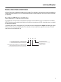
The following code system is used to identify any Fuller model transmission equipped with a complete Rear Mount Multi-Speed
PTO Neutral Interlock System or partial system. This information is to be stamped in the upper left hand corner (“PTO Code”
block) of transmission identification tag.
X
L = Top Extended Coutershaft Present - U.S./Chelsea Design Shaft
T = Top Left Extended Countershaft Present - U.K. Design Shaft
O = No Extended Countershaft Present in This Position (Top Left)
R = Bottom Right Extended Countershaft Present - U.S./Chelsea Design Shaft
B = Bottom Right Extended Countershaft Present- U.K. Design Shaft
O = No Extended Countershaft Present In This Postion (Bottom Right)
X
X
-
X
A= Complete Neutralizer System
B= Partial Neutralizer Syetem (PTO Prepared)
O= No Neutralizer System
O = This Space Reserved
2
Installation
Introduction
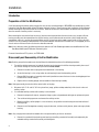
Preparation of Unit for Modification
A shift bar housing with neutral switch provision the slave air valve actuating plunger IS REQUIRED when modifying any unit to
include the Fuller Rear Mount Multi-Speed PTO Neutral Interlock System. In some instances, their installation can be performed
without removing the transmission from vehicle chassis. However, the lubricant should ALWAYS be drained from transmission
when the removal of auxiliary section is necessary.
When removing the transmission from the chassis, lubricant must be drained from the transmission case, the gear shift lever
housing assembly must be removed from the shift bar housing, and all other external connections (clutch linkage, driveline,
speedometer cable, etc.) must be disconnected. Make sure the air hose from vehicle supply source and all air lines to the shift
controls in the cab (including the deep reduction valve and extended rear countershaft PTO control valve, if so equipped) or at the
slave air valve on the transmission case have also been disconnected.
Note: Unless otherwise stated, the following instructions pertain to all Fuller Roadranger models to be modified with the Fuller
Rear Mount Multi-Speed PTO Neutral Interlock System.
For more information on PTO systems, see TRDR-0900.
Disassembly and Reassembly of Unit for Modification
Note: Refer to your particular model series Service Manual for detailed instructions of the following procedures.
1.
Turn out the retaining capscrews, jar to break the gasket seal and remove the shift bar housing assembly from case. If
the shift bar housing has a neutral switch provision and can be reused...
a.
Remove the neutral switch or plug from the threaded hole in the housing.
b.
Secure the housing in a vise, using caution to avoid marring the machined mounting surface.
c.
Remove ONLY those parts of assembly which make it possible to remove the slave air valve actuating plunger from
the bore in the shift bar housing.
d.
Replace with an actuating plunger and reassemble shift bar housing assembly.
Note: During reassembly, do not reinstall the neutral switch or the plug.
2.
Disconnect all 1/4” I.D. and 1/8” O.D. air system lines (range, splitter and deep reduction) at the slave air valve and
auxiliary section.
3.
If an extended auxiliary countershaft assembly is to be installed...
a.
Remove the output shaft stop nut, companion flange or yoke, and speedometer drive gear or replacement spacer.
b.
Turn out the retaining capscrews and remove the auxiliary section.
c.
Mount the auxiliary section upright in a vise and secure, using caution to avoid marring the machined surface of
housing flange.
d.
Remove the air filter/regulator assembly, range cylinder cover, nut from end of yoke bar, piston and range cylinder
housing.
Note: Only a range piston removed from models with a two-speed auxiliary section can be reused.
e.
3
Remove the countershaft rear bearing cover, bearing and auxiliary countershaft assembly to be replaced by the
extended auxiliary countershaft assembly and related parts.
Installation
Note: For auxiliary sections of 13-speed splitter models only, removal of the range yoke and bar, synchronizer assembly, and low
range mainshaft gear MUST BE PERFORMED to remove the auxiliary countershaft assembly.
f.
Mark the tooth of the extended auxiliary countershaft assembly which is stamped with an “O” on the low range gear
of models with a two-speed auxiliary section / the splitter gear of 13-speed splitter models / the reduction gear of
deep reduction miles.
g.
Place the extended auxiliary countershaft assembly into position with the marked tooth between the two marked
teeth of the mating gear on the mainshaft. Make sure that the “timing marks” of other countershafts are still in
proper mesh.
h.
Install the countershaft rear bearing, making sure that both countershafts are still in time.
Note: For auxiliary sections of 13-speed splitter models only, installation of the low range mainshaft gear and synchronizer
assembly must be performed prior to installing the rear countershaft bearing. Only then should the range yoke and bar be
installed.
4.
If an extended auxiliary countershaft assembly is not to be installed...
a.
Remove the air filter/regulator assembly, range cylinder cover, nut from the end of the yoke bar, piston and range
cylinder housing, leaving the yoke bar to protrude in bore of auxiliary section.
Note: Only a range piston removed from models with a two-speed auxiliary section can be reused.
5.
When applicable, turn out the retaining cap screws and remove the splitter or deep reduction cover only.
4
Installation
Precautions
IMPORTANT: To ensure proper operation and expected life from the parts contained in the Fuller Rear Mount Multi-Speed PTO
Neutral Interlock System, use the following precautions during assembly and installation.
5
1.
GASKETS - Make sure new gaskets are installed throughout the unit as it is being rebuilt. The omission of any gasket
can result in oil leakage or misalignment of parts.
2.
CAPSCREWS/THREADED FASTENERS - To prevent air and oil leakage, apply Loctite 242 sealant to threads of all capscrews, adapter, neutral switch, hex pilot, and at both ends of or range piston spacer. Torque fasteners to recommended
ratings as noted in the following procedures.
3.
O-RINGS - Apply silicone lubricant to all o-rings so that a film of lubricant covers the entire surface of each O-ring.
4.
AIR FITTING/HOSES - To prevent air leakage, apply sealant to all air fittings and hose connections. Sealant must cover
at least three complete and consecutive threads beginning with the first three threads of each part to be installed.
5.
CYLINDER BORES - Apply rust preventative to the cylinder bores of neutral/range cylinder housing (neutral plunger,
range yoke bar, and piston bored), splitter/deep reduction position sensing cylinder cover (valve actuation pin and piston-pin bores), and hex pilot (piston-pin bore). A film of rust preventative should completely cover these finished bore
surfaces.
6.
INITIAL LUBRICATION - To prevent premature wear, an application of Moly Kote ‘G’ should completely cover the areas
specified on the following parts.
a.
The shanks and bores of actuation pins used with sequencing protection valve, air shut-off valve, splitter/deep
reduction position sensing valve, and neutral switch.
b.
The shank and point of neutral plunger and shank bore of cylinder housing.
c.
The chamfered edges of reaction washers.
d.
The surfaces of or range piston spacer that contact the reaction washers.
e.
The O.D. of front and rear range pistons.
f.
The O.D.’s of splitter/deep reduction position sensing piston-pin
Installation
Assembly and Installation of Parts for Modification
Note: For clarification of the following procedures, refer to the sectional views and charts provided in the back of this section or
the appropriate Illustrated Parts List.
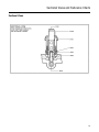
A. Neutral/Range Cylinder Assembly
1.
Install two o-rings in position in the neutral plunger bore and range yoke bar bore of neutral/range cylinder housing.
2.
Thread the stud to full depth of 3/4” length threads into upper left tapped hole of auxiliary housing for mounting the
neutral/range cylinder housing in the vertical position.
Note: If cylinder housing is to mounted in the horizontal position, stud must be threaded into upper right tapped hole in the same
manner described.
3.
Using the stud to position the gasket on the auxiliary housing, install the neutral/range cylinder housing, piloting on the
yoke bar. Secure with the lockwasher and the hex nut on stud and three capscrews using 35-45 lbs. ft. of torque.
Note: In most cases, the cylinder housing mounted in the vertical position will provide sufficient frame clearance under the vehicle for the transmission to be installed properly. However, should it become necessary to mount the housing in the horizontal position, different air hoses from those noted in these instructions will be required.
4.
Install the o-rings in I.D. on the front range piston.
Note: The range piston is used on models with a two-speed auxiliary section only.
5.
Install front range piston on the yoke bar in the cylinder bore with O.D. chamber of or the shoulder forward.
6.
Install the reaction washer on either shank of range piston spacer (models with a two-speed auxiliary section only) or
on the longest shank of the range piston spacer. Thread this two-piece assembly onto the yoke bar using 70-85 lbs. ft.
of torque to secure the washer against piston.
7.
Install the other reaction washer one shank of the range piston spacer protruding in the cylinder bore.
8.
Install the o-ring on O.D. of the rear range piston.
9.
Install the rear range piston and gasket on the capscrew. Thread the capscrew of this three-piece assembly into range
piston spacer, making sure that the gasket is between the spacer and the piston, and tighten with 60-75 lbs. ft. of
torque.
10. Position the gasket on the range cylinder cover mounting surface and re-install range cylinder cover so that the 45°
elbow air fitting is to the upper left. Secure with the same (4) capscrews removed earlier using 35-45 lbs. ft. of torque.
11. Install the o-ring on piston O.D. of neutral plunger.
12. Empty entire contents (4cc tube) of silicone lubricant into the neutral plunger bore, applying lubricant to the bottom of
the range cylinder bore between the reaction washers.
13. Install neutral plunger in cylinder bore of neutral/range cylinder housing.
14. Position the gasket on the neutral cylinder cover mounting surface and install neutral cylinder cover. Secure with (4) X505 capscrews and X-3-500 lockwashers using 20-25 lbs. ft. of torque.
15. Thread the breather in the threaded bore on the lower right side of the neutral/range cylinder housing.
6
Installation
B. Air Shut-Off Valve Assembly
1.
Install actuating pin in the bore on left side of the neutral/range cylinder housing.
2.
Thread the following air fittings into the ports of air shut-off valve:
a.
Install the 45° elbow into the “IN” port on bottom of valve. Tighten so that the opening of the air fitting points forward and 45° to the RIGHT (as if the valve was installed).
b.
Install 90° street ell into the “C1” port on the top right of the valve. Tighten so that the opening of the air fitting
points forward. For models with a three-speed auxiliary section ONLY: Add the 1/8” nipple street ell and the street
tee are to the LEFT and RIGHT.
c.
Install the 1/8” nipple into the “C2” port on the top left of the valve. Add the 90° street ell and tighten so that the
opening of the air fitting points forward.
3.
Position air shut-off valve on the mounting surface on the neutral/range cylinder housing with the “IN” port side DOWN
and the valve plunger contacting actuating pin in bore. Secure with assembly of two capscrews, lockwasher, and valve
plate using 8-12 lbs. ft. of torque on capscrews.
4.
With valve secured in proper mounted position, bend lock tabs of lockwasher over to retain capscrews.
C. Neutral Switch
1.
Install the actuating pin in the bore on the right side of the neutral/range cylinder housing.
2.
Thread neutral switch into the cylinder housing and tighten with 40 lbs. ft. of torque maximum.
D. Air Filter/Regulator Assembly
1.
Install the air filter/regulator assembly on range cylinder cover with supply INLET to the RIGHT. Secure with two capscrews using 8-12 lbs. ft. of torque.
2.
If the assembly is being re-used, make sure both ports on the left side are plugged. Use the 1/8” plug if needed.
3.
Install the 1/8” nipple into bottom right OUTLET port and the street tee onto nipple. Tighten so that the openings of the
tee are to the FRONT and BACK.
E. Splitter/Deep Reduction Position Sensing Valve and Cover Assembly (Models with a
Three-Speed Auxiliary Section ONLY)
7
1.
Install the o-ring in piston-pin bore of splitter/deep reduction position sensing cover.
2.
Position the gasket on cover mounting surface and install the sensing cover so that the mounting surface for the sensing valve is to the LEFT. Secure with four capscrews using 20-25 lbs. ft. of torque.
3.
Install the o-ring on piston O.D. of the sensing piston-pin.
4.
Install the sensing piston-pin in cover bore at rear.
5.
Thread the 90° elbow into the splitter/deep reduction port of cover (directly above sensing piston) and tighten so that
the opening of air fitting is to the LEFT.
6.
Thread the hex pilot into cover and tighten with 40 lbs. ft. of torque MAXIMUM.
7.
Thread the street ell 90° into hex pilot and tighten so that the opening of the air fitting is to the LEFT.
8.
Install the insert valve into bottom port of cover with the flat end of valve facing up.
9.
Thread the cylinder cover plug into cover to retain insert valve and tighten with 40-50 lbs. ft. of torque.
Installation
10. Install the actuating pin in bore on left side of splitter/deep reduction position sensing cover.
11. Thread the street ell into 90° the “CYL” port on top of the splitter/deep reduction position sensing valve. Tighten so that
opening of air fitting point FORWARD (as if valve was installed).
12. Thread the 1/8” nipple into the “NO” port on bottom left of the sensing valve. Add the street tee and tighten so that
openings of tee are to the FRONT and REAR. Thread the 90° street ell into FRONT opening of tee and tighten so that
opening of ell is to the LEFT.
13. Thread the breather into the “NC” port on bottom right of the sensing valve and tighten.
14. Position the splitter/deep reduction position sensing valve on mounting surface of sensing cover with the “CYL” port
side UP and valve plunger contacting the actuating pin in bore. Secure with assembly of two capscrews, lockwasher and
the valve plate using 8-12 lbs. ft. of torque on the capscrews.
15. With the valve secured in proper mounted position, bend the locking tabs of the lockwasher over to retain capscrews.
F. The Modified Auxiliary Section
Note: Refer to your particular model series Service Manual for detailed instructions of the following procedures.
1.
Remove the auxiliary section from vise and install on the front section of transmission.
Important: Make sure that the bearing inner race has been installed on the front of each auxiliary countershaft.
2.
When applicable, RE-INSTALL the speedometer drive gear or replacement spacer, companion flange or yoke, and output shaft stop nut. Tighten nut on output shaft using 400-450 lbs. ft. of torque.
Note: For auxiliary sections TWO extended auxiliary countershaft assemblies, it MAY become necessary to replace the main rear
bearing cover and gasket PRIOR to re-installation of above parts. Refer to the charts provided in the back of this section.
3.
If the installation of an extended rear countershaft PTO is to follow, refer to the detailed instructions provided in the
manufacturer’s installation manual.
G. Shift Bar Housing Assembly
Note: Refer to your particular model series Service Manual for detailed instructions of the following procedures.
1.
After placing the mainshaft sliding clutches in the neutral position, install the shift bar housing gasket in position on the
case.
2.
Making sure that the shift bars are placed in the neutral position, install the shift bar housing assembly (with neutral
switch provision and the actuation plunger) on the transmission, fitting the shift yokes into corresponding grooves of
the mainshaft sliding clutches. Secure with capscrews using 35-45 lbs. ft. of torque.
H. Sequencing Protection Valve
1.
Thread the adapter into the neutral switch provision of the shift bar housing and tighten using 40-50 lbs. ft. of torque.
2.
Install the spring in the counterbore of the adapter and actuating pin into spring I.D.
3.
Position the sequencing protection valve on the adapter so that the “CYL” port side is to the LEFT of the transmission
and the valve plunger is contacting the actuating pin in bore of adapter. Secure with the valve plate and two capscrews
using 8-12 lbs. ft. of torque.
Note: To ensure the valve will operate properly, make sure the valve plunger is CENTERED on the head of the actuating pin when
mounted.
4.
With valve secured in proper mounted position, use lock wires to retain capscrews.
8
Installation
5.
Thread the breather into the “NO” port of sequencing protection valve and tighten.
6.
Thread the nipple into the “NC” port of the sequencing protection valve. Add the street tee and tighten so that the openings of tee are to the FRONT and RIGHT of transmission.
7.
Thread the 90° street ell into the pilot port on the top of the valve and tighten so that the opening of the air fitting points
to the FRONT. Use caution when tightening as NOT to collapse the valve neck.
I. Gear Shift Lever Housing Assembly
Note: Refer to your particular model series Service Manual for detailed instructions of the following procedures.
1.
Position the gasket on the mounting surface of the shift bar housing and RE-INSTALL the gear shift lever housing
assembly. Secure with same (4) capscrews removed earlier and tighten using 35-45 lbs. ft. of torque.
2.
For deep reduction models ONLY, remove the range control valve or A-5010 Roadranger valve from the mounted position on the gear shift lever and REPLACE with A-5015 Roadranger valve.
Note: The deep reduction valve mounted in the dash or elsewhere in the cab is NOT to be used when such models are equipped
with the Fuller Rear Mount Multi-Speed PTO Neutral Interlock System. All other models, however, make use of existing shift
controls when modified.
J. Stationary/Mobile Control Valve
1.
Install the stationary/mobile control valve on the vehicle dash or elsewhere in the cab so that the green light provision in
the base plate is FORWARD and provides easy access to valve ports for connecting air lines.
Note: The mounting valve on a separate bracket with the bracket secured to the vehicle dash or floor MAY be preferred. This
valve should be mounted in close proximity to the extended rear countershaft PTO control valve. See manufacturer’s installation manual.
2.
Install the control valve dial on the valve base plate and the indicator light in the hole provided.
3.
Mount the following adhesive-backed operating instructions label in vehicle cab and in clear view of operator:
a.
Adhere the label for models with a modified two-speed auxiliary section ONLY.
b.
Adhere the label for modified 13-speed splitter models ONLY.
c.
Adhere the label for modified deep reduction models ONLY.
Note: The appropriate label MUST be mounted on a non-combustible material which complies with Federal Motor Vehicle Safety
Standard No. 302.
K. Air System (refer to Air System Schematics)
Note: The following procedures are performed with the transmission installed in the vehicle.
9
1.
Thread the 90° elbow into the engage INLET (bottom LEFT port) of the stationary/mobile control valve and the 90°
elbow into the REAR opening of the tee fitting at the supply OUTLET (upper LEFT port) of the stationary/mobile control
valve and tighten.
2.
Thread the 90° elbow into the return INLET (bottom RIGHT port) of stationary/mobile control valve and the nipple into
the opening of ell fitting at the “C2” port on the air shut-off valve. Tighten and connect the 1/4” O.D. air line between the
fittings.
Installation
3.
Thread the nipple into the engage OUTLET (upper LEFT port) of stationary/mobile control valve and tighten.
a.
For models with a two-speed auxiliary section ONLY, thread the 90° elbow into the port of the neutral cylinder cover
and tighten the fitting so that the opening is to the FRONT of the transmission.
b.
For a 13-speed splitter AND deep reduction models, thread the 90° elbow or the nipple into REAR opening of the
tee fitting at the “NO” port on the splitter/deep reduction position sensing valve and tighten (opening of elbow fitting UPWARD). Connect 1/4” O.D. air line between the fittings specified above.
4.
Thread the nipple into the return OUTLET (upper RIGHT port) of the stationary/mobile control valve and the nipple into
the RIGHT opening of tee fitting at the “NC” port on sequencing protection valve. Tighten and connect 1/4” O.D. air line
between fittings.
5.
Connect the 1/4” I.D. air hose from the FRONT opening of the tee fitting at the “NC” port to the pilot port elbow fitting on
top of the sequencing protection valve.
6.
If not previously done, thread the 90° street ell into the rear port at the bottom of the neutral plunger and tighten so that
the opening is to the LEFT. Connect the 1/4” I.D. air hose (models with two-speed auxiliary section ONLY) or the 1/4”
I.D. air hose (models with a two-speed auxiliary section ONLY or the 1/4” I.D. air hose from this fitting on the neutral/
range cylinder housing to the “CYL” port of the sequencing protection valve.
7.
For 13-speed splitter AND deep reduction models ONLY:
a.
Thread the 90° street ell into the port of the neutral cylinder cover and tighten the fitting so that the opening is to
the LEFT of the transmission. Connect the 1/4” I.D. air hose from this fitting to the street ell at the “CYL” port of
splitter/deep reduction position sensing valve.
b.
Connect the 1/4” I.D. air hose from the ell fitting in the FRONT opening of the tee fitting at the “NO” port of the splitter/deep reduction position sensing valve to the ell fitting at the hex pilot port of the splitter/deep reduction position
the sensing cover.
c.
Connect the 1/4” I.D. air hose from the supply port of the sensing cover to the RIGHT opening in the tee fitting at
the “C1” port of the air shut-off valve. Loop the hose under neutral/range cylinder housing, and secure with the
hose clamp to the bottom flange of the auxiliary housing.
8.
Connect the 1/4” I.D. air hose from the 45° elbow fitting at the “IN” port of the air shut-off valve to the FRONT opening
tee fitting at the supply OUTLET of the air filter/regulator assembly. The hose should be looped under the neutral/range
cylinder housing.
9.
For deep reduction models ONLY:
a.
Remove the street tee and the nipple from the “S” or supply port of the slave air valve.
b.
Remove the street ell from the “L” or low range port of slave air valve.
c.
Re-install the nipple in the “L” or low range port of the slave air valve, adding the street tee to the nipple. Tighten
the tee fitting so that the openings are to the FRONT and REAR of the transmission.
d.
Thread the 90° elbow into the supply port of the A-4688 slave air valve ONLY. Models otherwise equipped with the
slave air valve, RE-INSTALL the street ell in the “S” port. Tighten fitting specified so that the opening is to the REAR
of the transmission.
10. Connect the 1/4” I.D. air hose (models with a two-speed auxiliary section ONLY) or the 1/4” I.D. air hose from fitting at
the “S” or supply port of the slave air valve to the fitting at the “C1” port of air the shut-off valve (LEFT opening of the tee
fitting on 13-speed splitter and deep reduction models).
Note: If the transmission is equipped with an A-4688 slave air valve, it may be necessary to use a longer length air hose.
11. If not previously done, thread the 90° elbow into the low range port of the neutral/range cylinder housing and tighten so
that the opening is to the LEFT FRONT of transmission. The 1/4” I.D. air hose (models with a two-speed auxiliary section
ONLY) or 1/4” I.D. air hose from the fitting at the low range port of the neutral/range cylinder housing to fitting at the “L”
or low range port of the slave air valve (the REAR opening of tee fitting on deep reduction models).
10
Installation
12. Connect the 1/4” I.D. air hose (models with a two-speed auxiliary section ONLY) or the 1/4” I.D. air hose (13-speed
splitter models ONLY) or the 1/4” I.D. air hose (deep reduction models ONLY) from the 45° elbow fitting in the range
cylinder cover (high range port) to the fitting at the “H” or high range port of the slave air valve (the REAR opening of
tee fitting on 13-speed splitter models).
13. When applicable, use the hose clamps at the top of the auxiliary section to secure ALL 1/4” I.D. air hoses installed on
the transmission in steps #6, #7A, and #10 - #12.
14. Connect 1/8” O.D. air line (white) from the INLET of the range control valve/”S” port of Roadranger control valve to the
fitting at the “S” or the supply port of the slave air valve.
15. Connect 1/8” O.D. air line (black) from the OUTLET of the range control valve/”P” port of Roadranger control valve to
the fitting at the “P” or end port of the slave air valve.
16. For 13-speed splitter models ONLY:
a.
Connect 1/8” O.D. air line from the “S” port of the splitter control valve/”H” port of the master control valve to the
opening in the tee fitting at the “H” or high range port of the slave air valve.
b.
Connect 1/8” O.D. air line from the “D” port of the splitter control valve/”SP” port of the master control valve to the
fitting at the splitter supply port of the sensing cover on the auxiliary.
17. For deep reduction models ONLY:
a.
Connect 1/8” O.D. air line from the “H” port of the master control valve to the opening in the tee fitting at the “L” or
low range port of the slave air valve.
b.
Connect 1/8” O.D. air line from the “SP” port of the master control valve to the fitting at the deep reduction supply
port of the sensing cover on the auxiliary.
L. Electrical System (Refer to Electrical Schematic.)
1.
Connect lead wire from pigtail of the indicator light to the vehicle ground.
2.
Connect lead wire from remaining terminal at the indicator light to the terminal of the neutral switch.
3.
Connect fuse wire from positive terminal of vehicle power source to the remaining terminal at the neutral switch.
Preparation of Modified Unit for Operation
When applicable, an extended rear countershaft PTO control valve should be mounted in close proximity to the stationary/mobile
control valve in the cab with connections of electrical and air lines made in accordance to the manufacturer’s installation manual.
Connect all other external components to the transmission, such as the clutch linkage, driveline, speedometer cable, etc., and
refill the modified unit with the proper type, grade, and quantity of lubricant as recommended in your Fuller transmission Service
Manual or the Roadranger Product Lubrication Manual, TCMT-0021.
11
Installation
Shift Lever and System Checklist
System Checklist
Prior to placing the vehicle into operation, make the following system checks of the transmission to ensure it will function properly with the installation of the Fuller Rear Mount Multi-Speed PTO Neutral Interlock System. Unless otherwise stated in the following checklist, each system check with the corresponding result applies to any Fuller Roadranger model so modified.
CAUTION: DO NOT ATTEMPT TO OPERATE THE VEHICLE SHOULD THE RESULT OF ANY CHECK BE OTHER THAN
THAT GIVEN as damage to the unit and/or personal injury MAY result from improper installation and function of this
system.
1. With the gear shift lever in the neutral position and the mobile/stationary control valve knob in the
“MOBILE” mode:
Does it range shift properly?
YES
Does it complete the splitter/deep reduction shift properly? (“Not applicable” for models with a two-speed
auxiliary section.)
YES
2. With the gear shift lever STILL in the neutral position and the mobile/stationary control valve knob moved
to the “STATIONARY”:
Does the neutral switch close contact?
YES
Does it range shift?
NO
Does it complete the splitter/deep reduction shift while in LOW RANGE? (“Not applicable” for models with a
two-speed auxiliary section and 13-speed splitter models.)
NO
Does it complete the splitter/deep reduction shift while in HIGH RANGE? ("Not applicable” for models with a
two-speed auxiliary section and deep reduction models.
NO
3. With the gear shift lever STILL in the neutral position and the mobile/stationary control valve knob moved
to the “STATIONARY’’ mode:
Is the output shaft permitted to turn freely while in LOW RANGE and HIGH RANGE? (When applicable, with
splitter/ deep reduction button forward and rearward.)
YES
4. With the gear shift lever STILL in an in-gear position and the mobile/stationary control valve knob moved
to the “MOBILE” mode:
Are the neutral switch contacts closed?
YES
Does it range shift?
NO
Does it complete the splitter/deep reduction shift while in LOW RANGE? (“Not applicable” for models with a
two-speed auxiliary section and 13-speed splitter models.)
NO
Does it complete the splitter/deep reduction shift while in HIGH RANGE? (“Not applicable” for models with a
two-speed auxiliary section and deep reduction models.
NO
5. With the gear shift lever moved to the neutral position and the mobile/stationary control valve knob STILL
in the “MOBILE” mode:
Does the neutral switch close contact?
NO
Does it range shift properly?
YES
Does it complete the splitter/deep reduction shift properly? (“Not applicable” for models with a two-speed
auxiliary section.)
YES
12
Sectional Views and Reference Charts
Models with a Two-Speed Auxiliary Section
13
Sectional Views and Reference Charts
Deep Reduction Models
14
Sectional Views and Reference Charts
13-Speed Splitter Models
15
Sectional Views and Reference Charts
Sectional Views
16
Sectional Views and Reference Charts
Electrical Schematic - Neutral Light Circuit
17
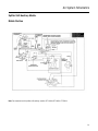
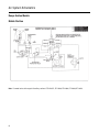
Air System Schematics
Splitter Shift Auxiliary Models
Mobile Position
Note: For model series with splitter shift auxiliary sections: RT-116313, RT-14613, RT-15613.
18
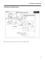
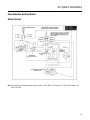
Air System Schematics
Stationary Position
Note: For model series with splitter shift auxiliary sections: RT-11613, RT-14613, RT-15613.
19
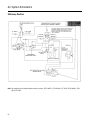
Air System Schematics
From Stationary to Mobile Position
Note: For model series with splitter auxiliary sections: RT-11613, RT-14613, RT-15613.
20
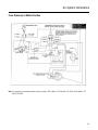
Air System Schematics
Range Section Models
Mobile Position
Note: For model series with range shift auxiliary sections: RTO-11607L, RT-11609, RT-14608, RT-14609, RT-14610.
21
Air System Schematics
Stationary Position
Note: For model series with range shift auxiliary sections: RTO-11607L, RT-11608, RT-11609, RT-11610, RT-14608, RT-14609,
RT-14610.
22
Air System Schematics
From Stationary to Mobile Position
Note: For model series with range shift auxiliary sections: RTO-11607L, RT-11608, RT-11609, RT-11610, RT-14608, RT-14609,
RT-4610.
23
Air System Schematics
Deep Reduction Auxiliary Models
Mobile Position
Note: For model series with deep reduction auxiliary sections: RTO-11607LL, RTO-11608LL, RT-11615, RTO-14608LL, RT14615, RT-15615.
24
Air System Schematics
Stationary Position
Note: For model series with deep reduction auxiliary sections: RTO-11607LL, RTO-11608LL, RT-11615, RTO-14608LL, RTO14615, RT-15615.
25
Air System Schematics
From Stationary to Mobile Position
Note: For model series with deep reduction auxiliary sections: RTO-11607LL, RTO-11608LL, RT-11615, RTO-14608LL, RT14615, RT-15615.
26
Troubleshooting
Forward
The purpose of this section is to assist the mechanic in analyzing and location the trouble so necessary repairs to the transmission can be made. Emphasis is placed on troubleshooting specific problems with the operation of the Multi-Speed PTO. Refer to
your service manual and troubleshooting guide when confronted with a problem not discussed in the following.
WARNING: Do not attempt to repair a transmission or multi-speed PTO while under the vehicle when the engine is running as personal injury or death MAY result from sudden and unintended movement of the vehicle.
If the transmission will not shift to the “Stationary” mode (green light will not come on) use the following check-list to diagnose
the problem.
1.
Make sure the air line connections are correct. See Air System Schematics.
2.
For vehicles equipped with a 13-speed splitter model transmission only, the splitter button of the two-position splitter
control valve/master control valve MUST be in the “direct” or rearward position.
3.
For vehicles equipped with a deep reduction model transmission only, the deep reduction button of the A-5015 master
control valve MUST BE in the “out” or rearward position.
4.
Make sure the gear shift lever is in the neutral position.
5.
The stationary/mobile control valve knob MUST be in the “STATIONARY” position. (The plunger of the neutral cylinder
assembly should be in the DOWN position.)
6.
Check the 12-volt power source, fuse, switch on the neutral cylinder assembly, and the bulb in the green stationary
mode indicator light for failure and loose or incorrect electrical connections. See Electrical Schematic.
7.
Check air pressure in line from the air filter/regulator assembly to the “CYL” port of the air shut-off valve. (57.7 to 62.5
PSI for all pressurized lines).
8.
The air line from “C2” port of the air shut-off valve to the INLET port of the stationary/mobile control valve should be
pressurized.
9.
For vehicles equipped with a 13-speed splitter model transmission only:
a.
The air line from the outlet port of the stationary/mobile control valve to the “NO” port of the splitter position sensing valve should be pressurized.
b.
The air line from the “NO” port of the splitter position sensing valve to the rear port of the splitter cylinder cover
should also be pressurized, moving the yoke bar and piston forward and “LOCKING” the splitter cylinder in the
“DIRECT” position.
Note: Initially, the splitter piston was placed in the “DIRECT” position when operating in the “MOBILE” mode.
c.
The plunger of the splitter position sensing valve should drop down, allowing the “CYL” port to become pressurized and supply air in the line to the port on top of the neutral cylinder assembly.
d.
The neutral plunger should move downward, stopping the flow of air to the “C1” port of the air shut-off valve and
begin supplying it to the “C2” port of the same valve.
e.
Air in supply line to the splitter cylinder assembly from the “C1” port of the air shut-off valve should be exhausted.
10. For vehicles equipped with a deep reduction model transmission ONLY:
27
a.
The air line from the OUTLET port of the stationary/mobile control valve to the “NO” port of the deep reduction
position sensing valve should be pressurized.
b.
The air line from the “NO” port of deep reduction position sensing valve to the rear port of deep reduction cylinder
cover should also be pressurized, moving the yoke bar and piston forward and “locking” the deep reduction cylinder in the “DIRECT” or “OUT” position.
Troubleshooting
Note: Initially, the deep reduction cylinder was placed in the “DIRECT” or “OUT” position with the deep reduction button selection made when operating in “MOBILE” mode.
c.
The plunger of the deep reduction position sensing valve should drop down, allowing the “CYL” port to become
pressurized and supply air in line to the port on top of the neutral cylinder assembly.
d.
The neutral plunger should move downward, stopping the flow of air to the “C1” port of air shut-off valve and begin
supplying it to the “C2” port of the same valve.
e.
Air in the supply line to the deep reduction cylinder assembly from the “C1” port of air shut-off valve should be
exhausted.
11. For vehicles equipped with another Roadranger model transmission (models with a two-speed auxiliary section only):
a.
The air line from the OUTLET port of the stationary/mobile control valve to the port on top of the neutral cylinder
assembly should be pressurized.
b.
The neutral plunger should move downward, stopping the flow of air to the “C1” port of the air shut-off valve and
begin supplying it the “C2” port of the same valve.
12. The air in supply line to air slave air valve from the “C1” port of air shut-off valve should be exhausted.
13. Air in all lines connected to the slave air valve should be exhausted when in “STATIONARY.”
14. The plunger of the neutral cylinder assembly should be completely down, locking the range yoke bar and piston in the
centered position.
15. The auxiliary section should be in neutral.
If the Transmission will not shift from the “Stationary” to the “Mobile” mode (green light will not go out) use the following
checklist to diagnose the problem:
1.
Make sure the air line connections are correct. See Air System Schematics.
2.
Make sure the gear shift lever is in the NEUTRAL position.
3.
The stationary/mobile control valve knob must be in the “MOBILE” position. (The plunger of the neutral cylinder assembly MUST be in the UP position.)
4.
Check the 12-volt power source, fuse, switch on the neutral cylinder assembly, and the bulb in the green stationary
mode indicator light for failure and loose or incorrect electrical connections. See Electrical Schematic.
5.
Check the air pressure in line from the air filter/regulator assembly to the “CYL” port of the air shut-off valve. (57.5 to
62.5 PSI for all pressurized lines.)
6.
The air line from the OUTLET port of the stationary/mobile control valve to the “NC” and pilot ports of the sequencing
protection valve should be pressurized.
7.
The air line from “CYL” port of the sequencing protection valve to the side port (at bottom of plunger housing) of the
neutral cylinder assembly should be pressurized.
8.
The neutral plunger should move upward, and free the range yoke bar and piston from the locked position.
9.
The air in line to the INLET port of the stationary/mobile control valve from the “C2” port of air shut-off valve should be
exhausted and begin supplying it to the “C1” port of the same valve.
10. The air line from “C1” port of the air shut-off valve to the supply or the “S” port of the slave air valve should be pressurized.
11. The air line from the supply or the “S” port of the slave air valve to the INLET port of the range control valve or the “S”
port of master control valve should be pressurized.
12. The range yoke bar and the piston of the neutral cylinder assembly should move to the “direct”/high range or low range
position, whichever is selected.
28
Troubleshooting
13. The air line from the low range or “L” port of slave air valve to the port in the housing of the neutral cylinder assembly
should be pressurized when the range control is DOWN in the LOW RANGE position. Likewise, the air line from the high
range or “H” port of slave air valve to the port in the cover of neutral cylinder assembly should be pressurized when the
range control is UP in the high range position.
Troubleshooting Tips
29
•
If the transmission is hard to shift (difficult to move gear shift lever) and/or the auxiliary section will not shift from the
"STATIONARY" to the "MOBILE" mode check for a collapsed collar on the sequencing protection valve. If the nut or fitting
on top of the collar is over tightened the above complaint can result.
•
If the air lines and hoses are connected correctly but there is a constant air leak out of the breather of the sequencing
protection valve it indicates the valve is defective.
•
If air leaks from the breather of the sequencing protection valve only when the front box of the transmission is in gear it
indicates the 24023 o-ring on the neutralizer plunger is leaking or missing.
•
If one of the 20425 spacers are not installed in the range/neutralizer cylinder the transmission will not go into the "STATIONARY" mode from one range position.
•
It is extremely important to apply silicone to all o-rings and bores during assembly. The splitter position sensing valve
will not operate if silicone is not used on the bore for the 20444 piston or 15899 plunger.
•
Air lines connected to the stationary mobile control valve must be at least 1/4" I.D. Use of lines smaller than 1/4" I.D. will
cause slow shifts of the system.
Copyright Eaton Corporation, 2012.
Eaton hereby grant their customers,
vendors, or distributors permission
to freely copy, reproduce and/or
distribute this document in printed
format. It may be copied only in
its entirety without any changes or
modifications. THIS INFORMATION
IS NOT INTENDED FOR SALE OR
RESALE, AND THIS NOTICE MUST
REMAIN ON ALL COPIES.
Note: Features and specifications
listed in this document are subject to
change without notice and represent
the maximum capabilities of the
software and products with all options
installed. Although every attempt has
been made to ensure the accuracy of
information contained within, Eaton
makes no representation about the
completeness, correctness or accuracy
and assumes no responsibility for
any errors or omissions. Features and
functionality may vary depending on
selected options.
For spec’ing or service assistance,
call 1-800-826-HELP (4357) or visit
www.eaton.com/roadranger.
In Mexico, call 001-800-826-4357.
Roadranger: Eaton and trusted partners
providing the best products and services in the
industry, ensuring more time on the road.
Eaton Corporation
Vehicle Group
P.O. Box 4013
Kalamazoo, MI 49003 USA
800-826-HELP (4357)
www.eaton.com/roadranger
Printed in USA