1
Search
Table of Contents
Vehicle System Tools
Brake and Steering Systems........................................................................................................................................ 7-3
Hydraulic System Tools............................................................................................................................................... 7-38
Hydraulic Component Disassembly and Assembly............................................................................................. 7-132
Motor Grader Controls, Cable Control and Winch............................................................................................... 7-228
Loader Lift Arm and Excavator Implement............................................................................................................ 7-236
Implements, Frame, Hitch and Suspension........................................................................................................... 7-286
Vehicle System Tools
Home
7-1
Search
7-2
Home
Vehicle System Tools
Table of Contents
Search
Brake and Steering Systems
Brake and Steering Systems
2617527
5B-3032 Brake and Clutch Adjusting Tool
SMCS Code: 3058-025
Model: See Below
Warranty: Six Months
•
Used to adjust brakes and flywheel clutches on earlier
motor graders and to adjust flywheel clutches on DW10,
DW15, DW20 and DW21 Tractors
Part Number
5B-3032
Description
Brake and Clutch Adjusting
Tool
2617542
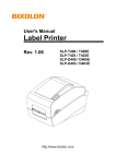
242-0992 Brake Gauge
SMCS Code: 4250-082, 0763
Model: TH103 Telehandler, B-Series Telehandlers, and Backhoe Loaders
Warranty: Six Months
Used to check brake disc wear (checks minimum thickness between brake discs)
• Easily determines if replacement is needed (if gauge fits
between brake discs, they do not require replacement)
• Gauge is inserted through axle housing inspection port
• Stamped with “This Side Up” to eliminate misuse of the
gauge
Overall size
6.35 mm (0.25 in) square x
180.0 mm (7.1 in) long
Material
Steel with black oxide coating
Part Number
242-0992
Vehicle System Tools
•
Description
Brake Gauge
Home
7-3
Brake and Steering Systems
Search
2617561
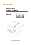
273-3148 Brake Purge Group
Essential Tool
SMCS Code: 4257
Model: TH210 (CEC1-Up, MHT1-Up), TH215 (CEG1-Up, MHS1-Up) Telehandler
Warranty: Six Months
Vehicle System Tools
Part Number
273-3148
2617578
•
Used to purge air from auxiliary brake line for trailers,
implements, and other similar types of equipment
•
Used to adjust brakes
•
Used for the assembly and disassembly of spring-actuated emergency and parking brake air chamber mechanisms
Prevents the spring jumping out when the brake chamber
is being worked on
Use with FT0586 Holding Tool
Material: SAE 1020 Steel
Assembly includes all items in figure
Description
Brake Purge Group
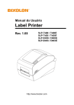
5S-9925 Brake Adjusting Tool
SMCS Code: 4250-025
Model: 12F, 14, 112E, 112F and 120 Motor Graders
Warranty: Six Months
Part Number
5S-9925
2617595
Description
Brake Adjusting Tool
7S-6704 Spring Compressor Assembly
SMCS Code: 4262-017
Model: 623E
Warranty: Six Months
•
•
•
•
(Continued)
7-4
Home
Search
7S-6704 Spring Compressor Assembly (Continued)
Brake and Steering Systems
2617595
SMCS Code: 4262-017
Model: 623E
Warranty: Six Months
Part Number
7S-6704
Description
Spring Compressor Assembly
2617615
9X-2233 Plug
SMCS Code: 4322-036
Model: 206 Excavator and 212 Excavator
Warranty: Six Months
•
•
•
Used to block line between steering pump and steering valve during pressure checks and adjustments of steering pump
relief valve
Make pressure check quick and easy
Usually not obtainable locally
Part Number
9X-2233
Description
Plug
2617634
FT0500 Brake Chamber Adjustment Gauge
SMCS Code: 4262-025
Model: 769 Truck
Warranty: None
Used to adjust air chambers
Material: SAE 1018 Steel
Vehicle System Tools
•
•
Home
7-5
Brake and Steering Systems
Search
2617648
FT0586 Holding Tool
SMCS Code: 4262-017
Model: Earlier Motor Graders
Warranty: None
•
Used to hold air brake chambers while being assembled
or disassembled
•
•
Allows brake system to be bled by one person
Requires two 132-3056 O-ring Seals (provided) when used
with hydraulic oil
Features a self-contained, hand-pressurized pump, more
than 3 m (10 ft) hose with a shutoff, pressure gauge, and
quick coupler for use with other brake bleeder adapters to
provide easy hookup to brake bleeder valves
Capacity: 4 L (1 gal)
2617660
Vehicle System Tools
253-0987 Brake Bleeder
Essential Tool
SMCS Code: 4251-025
Model: B-Series Telehandlers
Warranty: Six Months
•
•
Part Number
253-0987
7-6
Description
Brake Bleeder
Home
Search
Brake and Steering Systems
2617678
9U-6265 Pliers
SMCS Code: 4253-010, 0603
Warranty: Six Months
•
•
Replaces discontinued 1P-0541 Pliers
Used to compress brake shoe springs
Part Number
9U-6265
Description
Pliers
2617693
135-9811 Brake Spring Pliers
SMCS Code: 4253-010
Model: M312 Wheeled Excavators
Warranty: Six Months
•
•
•
•
Used to remove and install extra-heavy brake springs
Replaceable tip ensures long tool life
Overall length: 66.0 cm (26.0 in)
Replaceable tip: 135-9879
Description
Brake Spring Pliers
2617712
FT0502 Retainer Compressor
SMCS Code: 4250-012
Model: 769 Truck
Warranty: None
•
•
Used on rear wheel brakes to compress floating DuoCone seal retainers into seals far enough to allow retaining ring to be installed
Material: SAE 1020 Steel
Home
7-7
Vehicle System Tools
Part Number
135-9811
Brake and Steering Systems
Search
2617726
Steering Lines Adapter Tools
SMCS Code: 4302-552
Model: 631B, 641, 651 and 657 Tractors
Warranty: Six Months
•
•
Vehicle System Tools
•
Part Number
1B-5174
4F-7226
3B-4507
2617752
Description
Plug
Bolt
Lock Washer
Quantity
—
4
8
Used on tractors with steering swivel joints
Makes it possible to tow a tractor-scraper unit with tractor wheels on lowboy and scraper wheels on the ground
A junction block (part of steering lines adapter group) is
bolted to swivel joint with steering cylinder lines bolted to
junction block; junction block permits hydraulic steering
oil to flow freely between steering cylinders
Part Number
3H-5368
4J-0522
4J-7570
Description
Bolt
Seal (not shown)
Block
Quantity
4
4
—
FT2557 Gauge Plate
SMCS Code: 4314-016
Model: PS150 and PS250
Warranty: None
•
•
•
7-8
Used to provide access for measuring shim pack thickness between plate and king pin
123-4588 Plate should be removed from machine and
modified by adding a 1/8 -12 NPTF threaded hole
After measurement is taken and shim pack determined,
plug hole with 6V-2766 Plug and reuse plate on machine
Home
Search
Brake and Steering Systems
2617766
FT0510 Ring
SMCS Code: 4301-016
Model: 12, 14 Motor Graders; DW15, DW20 and 630A Tractors
Warranty: None
•
Used to keep centering springs in steering gear control
valve compressed while being assembled
2617781
FT0508 Block
SMCS Code: 4322-036
Model: 950, 966, 980 and 988 Loaders; 824 and 834 Tractors
Warranty: None
Vehicle System Tools
•
Used to check relief valve pressure by preventing machine from continuing its turn
Home
7-9
Brake and Steering Systems
Search
2617798
FT0509 Steering Cylinder Block
SMCS Code: 4303-009
Model: Articulated Wheel Loaders
Warranty: None
•
•
Prevents machine from turning while service work is being performed
Attach this block to steering cylinders on articulated
wheel loaders that are not equipped with safety links
2617811
FT0918 Brake Spring Tool
Vehicle System Tools
SMCS Code: 4253-010
Model: 621, 627, 631C, 633C, 637, 641, 650B, 651B, 657B, 660B, and 666B Tractor-Scrapers
Warranty: None
•
•
•
7-10
Used for brake spring removal and installation
Tang end used to lift spring hook out of brake shoe pin
groove; other end shaped to engage spring hook and
guide it over pin
Material: SAE 1020 Steel
Home
Search
Brake and Steering Systems
2617836
1U-9360 Displacement Gauge Assembly
SMCS Code: 4258-082, 4262-082
Model: 768B, 768C, 772, 772B Track-Type Tractors, 769B, 769C, 773, 773B Off-Highway Trucks
Warranty: Six Months
•
Formerly available as FT1097; inventoried due to dealer
interest
• Used to measure and check piston movement in master
cylinder and brake cylinder on the models listed above
(9J-1254 and 9J-1255 Brake Cylinder Groups)
• Movement indicates leaking seals on pistons
• Assembly includes all items in figure
References
SENR2940, Service Manual
SENR2960, Service Manual
SENR4763, Service Manual
SENR7868, Service Manual
Part Number
1U-9360
Description
Displacement Gauge Assembly
2617862
Vehicle System Tools
FT2504 Brake Gauge
SMCS Code: 4250-082, 0763
Model: TH62, TH63, TH82, and TH83 Telescopic Material Handler
Warranty: None
•
•
•
•
•
Used to check brake disk wear and determine whether
disk replacement is needed
Checks for minimum thickness between brake disks
Gauge is inserted through inspection port in axle housing
Can be made from 6.4 mm (0.25 in) square bar or key stock
Material: SAE 1018 Steel
Home
7-11
Brake and Steering Systems
Search
2617882
FT1048 Brake Anchor Pin Puller
SMCS Code: 4254-010
Model: IT12, 910, 920, 930
Warranty: None
•
•
Used to pull back brake anchor pins when replacing
wheel brake friction pads
Material: SAE 1020 Steel
2617899
FT1183 Brake Piston Retainer Tool
Model: 769B, 773, 768B and 772 Trucks
Warranty: None
Vehicle System Tools
•
•
•
Used to pressure check brake piston seals before assembling wheels
Retain brake piston in cylinder while seals are checked
with air pressure to 10.5 kg/cm² (150 psi)
Seals can also be pressure checked in event that wheel
assembly is performed on truck
2617917
5P-7428 Bearing Puller Adapter
SMCS Code: 6119-010, 4305-010
Model: 613B Scraper
Warranty: Six Months
•
Used with 9S-5559 Stud and 6V-3160 Hydraulic Puller to
remove 7J-6862 Steering Link Bushing from draft frame
(Continued)
7-12
Home
Search
Brake and Steering Systems
2617917
5P-7428 Bearing Puller Adapter (Continued)
SMCS Code: 6119-010, 4305-010
Model: 613B Scraper
Warranty: Six Months
Part Number
5P-7428
Description
Bearing Puller Adapter
2617933
FT1324 Spring Seat
SMCS Code: 4250-017
Model: 769B Truck
Warranty: None
•
•
•
Used with 5S-1330 Compressor and discontinued 5S-1326
Adapter to compress rear brake piston retraction springs
Makes operation easy and safe
Material: SAE 1020 Steel
FT1416 Brake Hub Retainer
SMCS Code: 4267-010
Model: 769C Truck
Warranty: None
•
•
•
Required for installation of brake assembly on rear axle (2
required)
With retainers holding brake hub firmly against brake
housing, brake discs are properly centered on splines of
inner brake hub
Necessary to center hub for subsequent installation of
wheel which must align with splines on hub and axle
housing at the same time
Home
7-13
Vehicle System Tools
2617948
Brake and Steering Systems
Search
2617963
5P-9726 Plug Gauge
SMCS Code: 4250-038
Model: 772B, 773B, 777, 785, 789
Warranty: Six Months
Used to check brake disc wear on service brakes
Installed stack height of brake disc pack is measured with brake piston in applied and retracted positions; if difference between the two measurements is
14.07 mm (0.554 in) or more, brake discs should be replaced
• Installed in place of the top 9D-6125 Brake Bleeder Screw Adapter
• Can be used with 1U-7425 Displacement Gauge Assembly for measurement
reading
• Service part: 6V-5722 O-ring Seal
NOTE:
A measurement of installed stack height of brake disc pack should be taken and
recorded with brakes applied after new discs have been “run in”. Measurements
should again be taken at prescribed intervals. If difference between initial and subsequent measurements exceed machine specifications, the brake discs should be
replaced.
Overall length
70.0 mm (2.75 in)
Hex size
25.4 mm (1.0 in)
Thread size
7/8 - 14
Vehicle System Tools
•
•
2617987
Part Number
5P-9726
Description
Plug Gauge
251-6568 Brake Adjuster Assembly
Essential Tool
SMCS Code: 4261-025
Model: 735 Articulated Truck (SN# AWR451-UP), 740 Articulated Truck (SN# AXM856-UP), 740 Articulated Ejector Truck (SN# AZZ294-UP)
Warranty: Six Months
•
•
•
•
Replaces 221-2589 Brake Adjuster Assembly
Used to simultaneously adjust check nut and adjuster screw on service brakes
Used with 1 1/2 inch wrench and 3/8 inch square drive ratchet
Use only on trucks with mechanical slack adjusters (not for use on hydraulically
operated slack adjusters)
• Use a 1 1/2 inch wrench to remove plug from service brake, install adapter, and
rotate socket
• Use a 3/8 inch drive ratchet to turn 6 mm ball socket hex bit
• Designed to keep socket and hex bit perfectly aligned during adjustment procedure
• Assembly includes all items in figure
References
735/740 Articulated Truck Disassembly and Assembly Manual
735/740 Articulated Truck, Brake System Module, in Machine Systems Test and
Adjusting
Part Number
251-6568
7-14
Description
Brake Adjuster Assembly
Home
Search
Brake and Steering Systems
2618010
Disc Brake Wear Gauges
Essential Tool
SMCS Code: 7473-040
Model: See below
Warranty: Six Months
•
•
Used to check brake disc wear on service brakes
May be used with 1U-7425 Displacement Gauge Assembly for measurement
reading
• Installed in place of brake inspection plug
• Service/Repair Part: 6V-5722 O-ring Seal
NOTE:
A measurement of installed stack height of brake disc pack should be taken and
recorded with brakes applied after new discs have been “run in.” Measurements
should again be taken at prescribed intervals. If difference between initial and subsequent measurements exceed machine specifications, the brake discs should be
replaced.
Part
Overall
Thread
Item Number Length
Hex Size Size
1
160-1726 158.0 mm 25.4 mm 7/8 - 14
(6.22 in) (1.0 in)
2
25.4 mm 7/8 - 14
(1.0 in)
25.4 mm 3/4 - 16
(1.0 in)
Model
D350E, D400E, 735, and
740 Articulated Trucks;
797 and 797B Offhighway Trucks
Bullet nose 733F, 775F, and 777F
Off-highway Trucks
Bullet nose 770 and 772 Off-highway Trucks
2618031
338-3572 Shim Kit
SMCS Code: 4269-025
Model: 966H and 972H Wheel Loaders
Warranty: Six Months
•
Used to check and set adjustment of brake light switch on
machines with dual brake pedals
• With 3.5 mm (.14 in) thick shims installed under pedal heel,
brake lights should be ON
• With 1.5 mm (.06 in) thick shims installed under pedal heel,
brake lights should be OFF
• Brake light switch adjustments are simultaneously done
with shims in place under both pedals
• Shim sets are connected by a 50.2 cm (19.8 in) long chain
which organizes the tooling yet allows both pedals to be
checked at the same time
• Each shim is stamped by size for easy identification
• Steel components are plated for corrosion resistance and
long service life
Reference
RENR8855, Testing and Adjusting, 966H Wheel Loader and 972H
Wheel Loader
Part Number
338-3572
Description
Shim Kit
Home
7-15
Vehicle System Tools
3
344-9164 135.0 mm
(5.31 in)
345-7976 135.0 mm
(5.31 in)
Tip Style
Ball nose
Brake and Steering Systems
Search
2618054
132-1415 Brake Piston Puller
Essential Tool
SMCS Code: 4256-011
Model: D250E Series II and D300E Series II Articulated Dump Trucks
Warranty: Six Months
Used to remove brake piston
Slides onto top of piston, fitting into piston groove
Grips piston for easier removal — reduces repair time
Helps eliminates potential damage to brake piston during
removal
Reference
SENR9129, Service Manual
Overall diameter
79.4 mm (3.13 in)
Inside diameter (brake piston) 67.5 mm (2.66 in)
Inside groove dimension
61.3 mm (2.41 in)
Vehicle System Tools
•
•
•
•
Part Number
132-1415
2618074
Description
Brake Piston Puller
164-4622 Clamp Assembly
Essential Tool
SMCS Code: 4250-017, 4267-017
Model: 785C and 793C Large Mining Truck, 24H Motor Grader
Warranty: Six Months
•
•
•
•
Used to compress parking brake piston guide spring
Required to disassemble and assemble brake group
Safely compresses guide spring
Locates over spring and guide — prevents tool from
disengaging
Clamp opening (max)
143.0 mm (5.63 in)
Clamp throat depth
89.0 mm (3.50 in)
Spring diameter (max)
34.0 mm (1.34 in)
Part Number
164-4622
7-16
Description
Clamp Assembly
Home
Search
Brake and Steering Systems
2618095
292-1274 Stop Group
Essential Tool
Model: 24M Motor Grader
Warranty: Six Months
• Used to stall steering pump for testing
• C-style clamp fits into bore
• Cap screw used to lock stop in place
• 8T-2223 Socket Head Bolt serviced separately
• Material: lightweight aluminum
Reference
KENR6022, 24M Machine System, Disassembly and Assembly
Part Number
292-1274
Description
Stop Group
2618112
Vehicle System Tools
5P-7389 Transparent Plug Assembly
5P-8678 Punch Assembly
SMCS Code: 4002-017
Model: 120G Motor Graders beginning with 87V-2262
Warranty: Six Months
•
•
•
Used to determine brake wear
Plug assembly, which contains a transparent plastic rod, is installed in spindle
housing port for viewing a mark on brake piston; with brakes applied, position of
mark as viewed through transparent plug assembly, is indicator of brake service
life remaining; when mark is no longer visible, brake should be rebuilt
At rebuild, punch assembly is installed in housing port and used to mark piston
Item
1
-2
Part Number
5P-7389
3K-0360
5P-8678
1
2
4K-2039
5F-9144
Description
Transparent Plug Assembly
Seal - O-ring - STOR
Punch Assembly
Not Shown
Seal
Seal
Home
7-17
Brake and Steering Systems
Search
2618135
5P-4197 Spacer
SMCS Code: 4205-010, 4234-010
Model: All “G” Series Motor Graders
Warranty: Six Months
•
•
Provides space necessary to pull front axle spindle king pins on
Has capacity to safely withstand compression load of both 6V-3160 and 6V-3175
Hydraulic Puller at full 703 kg/cm² (10,000 psi) maximum working pressure
Part Number
5P-4197
Description
Spacer
3038191
386-3378 Tire Lifting Bracket
Model Usage: 621H, 623H, 627H
Warranty: Six Months
Vehicle System Tools
European Union Compliant, CE marked
• Used to safely and easily remove and install tire assemblies on 621H, 623H and
627H series Wheel Tractor-Scrapers.
• Use with 142-1664 C-hook
• 397-4794 Roller Assemblies are black oxide coated for corrosion resistance
Specifications
Dimensions
1775 x 1217 x 902 mm (69.9 x 47.9 x 35.5 in)
Working Load Limit
1451 kg (3200 lb)
Weight
150 kg (331 lb)
Specifications
Part Number
386-3378
2980781
Description
Tire Lifting Bracket
Serviceable Parts
Roller Assembly
397-4794
390-0479 Wheel Alignment Tube Assembly
Model Usage: 621H, 623H, 627H
Warranty: Six Months
• Used to guide wheel assembly onto the spindle during installation
• Helps prevent damage to Duo-Cone seals during wheel assembly installation
• Black oxide coated for corrosion resistance
Reference
KENR9488, KENR8883 621H and 627H Wheel Tractor-Scraper
Power Train Disassembly & Assembly
Specifications
Dimensions
280 x 203 mm (11 x 7.9 in)
Weight
5.5 kg (12 lb)
Part Number
390-0479
7-18
Description
Wheel Alignment Tube Assembly
Home
Search
Brake and Steering Systems
2618151
Spherical Ballstud Bearing Installers
SMCS Code: 4303-017, 4318-010, 1253-017, 1253-016, 4303-010
Model: 769C, 773B and 777 Trucks
Warranty: None
• Used to remove and install spherical ballstud bearings in steering cylinders
• Material: SAE 1020 Steel
Part Number
Model
FT1443
773B and 777 Trucks
FT1447
769C Truck
2618169
FT2394 Wrench
SMCS Code: 4321-010
Model: 206B and 212B Excavators
Warranty: None
• Used to remove and install front steering cylinder linage knuckles
• Made from 4C-9815 Wrench
• Standard wrench will not fit on these steering knuckles
• 32 mm (1.26 in), forged steel, straight-handled, open end, black oxide finish
Reference
SENR4322, Power Train Disassembly and Assembly Manual
9U-6736 Parking Brake Spanner Wrench
SMCS Code: 4269-025
Model: 446 Backhoe Loader
Warranty: Six Months
•
Used to adjust parking brake linkage — makes adjustment much faster and
easier
References
SENR3971, Service Manual
Service Magazine, April 11, 1991
Part Number
9U-6736
Description
Parking Break Spanner Wrench
Home
7-19
Vehicle System Tools
2618186
Brake and Steering Systems
Search
2618202
FT1578 Puller Bar
SMCS Code: 4303-011
Model: 824C Wheel Tractors; 825C and 826C Compactors
Warranty: None
•
•
Required with two 5P-4776 Studs, two 1A-1935 Nuts, two 3K-5234 Washers, and
discontinued 5P-2997 Hydraulic Puller to remove steering cylinder clevis pins
Material: SAE 1018 Steel
2618218
FT3053 Spanner Wrench Assembly
Essential Tool
Vehicle System Tools
SMCS Code: 3275-015, 5631-015-BRK, 6637-015-BRK; 3275-016, 5631-016-BRK, 6637-016-BRK
Model: RM500 Road Reclaimer/Soil Stabilizer
Warranty: None
•
•
•
•
•
Used to remove and install spring housing on rotor brake
Used with 9/16 inch socket and torque wrench
Tool rods engage two holes in spring housing for easy removal and installation
Press and mandrel (dealer supplied) must be used to compress disc springs
before using tool to loosen or tighten spring housing
Made from SAE 1020M Steel for long service life
2618234
FT2468 Threaded Rod
SMCS Code: 4267-010
Model: 990 Wheel Loader
Warranty: None
•
•
•
•
7-20
Used to remove and install parking brake from transfer gear case
Remove two transfer gear case cover bolts and install two FT2468 threaded
rods; parking brake can then be removed and will slide out of case along tools
A ratchet puller, link brackets, and suitable sling will be necessary to lower
parking brake to ground or work surface
Material: SAE 4140 cold finish steel
Home
Search
Brake and Steering Systems
2618250
200-4422 Spring Compressor, 200-4423 Adapter Set
Essential Tool
SMCS Code: 4267-550
Model: D250, D300, D350, D400 Articulated Truck
Warranty: Six Months
• Used to replace parking brake activation spring
• Spring compressor is used with adapter set
• Used on Wabco parking brake actuator
• Square drive for guide (3): 1/2 inch
• Center to center pin distance: 38.1 mm (1.50 in)
• Set includes all items in Figure 2
Reference
HENR8086, Service Manual
Item
Description
1
Thrust Pad
2
Guide
3
Guide, 1/2 in square drive
Item
4
—
—
Part Number
045-5106
200-4422
200-4423
Description
Pin
Spring Compressor
Adapter Set
2618272
Vehicle System Tools
6V-0114 Brake Drum Gauge
SMCS Code: 6107-012
Model: 600 Series Wheel Tractor-Scrapers, with the exception of 613 and 613B
Warranty: Six Months
•
•
Used to quickly and easily check brake drums for reusability
Also, markings on gauge indicate whether standard or oversize brake linings
will be needed
References
SEBF8035, Guideline for Reusable Parts, Inspecting and Machining Brake Drums
SMHS6826, Special Instruction, Installation of Oversize Brake Linings
Part Number
6V-0114
Description
Brake Drum Gauge
2618290
FT1800 Plug
SMCS Code: 4208-017, 4251-017
Model: 824C Wheel Tractor; 980C Wheel Loader
Warranty: None
•
•
•
Replaces FT1536 Plug
Used with 7D-5962 Bolt to remove and install brake pistons
FT1800 Plug is 9S-4183 Plug with 12.7 mm (1/2 in) - 13-2B hole tapped through
center
Home
7-21
Brake and Steering Systems
Search
2618306
FT1451 Retraction Bolt
SMCS Code: 4262-010
Model: 641B Scrapers 65K-1150-up, 651B Scrapers 67K904-up and 657B Scrapers 68K-1201-up
Warranty: None
•
•
•
Used to retract brake rotochambers necessary for servicing brakes or towing
vehicle
Made by extending threads on 1D-4574 Bolt
To use retraction bolt, install 1A-7774 Flat Washer and thread it into 9D-8938
Brake Actuator to retract piston
2618323
5P-3569 Piston Press
SMCS Code: 4256-017, 4256-016
Model: 910, 920, 930 and 950 Wheel Loaders; 518 and 528 Logskidders; and Tree Harvesters
Warranty: Six Months
Vehicle System Tools
•
•
Used to facilitate installation of caliper disc brake pistons
Minimizes seal damage during piston installation
Part Number
5P-3569
Description
Piston Press
2618345
Steering Column Supports
SMCS Code: 7325-010
Model: 926, 926E, 936, 936E, 916, IT18B
Warranty: None
•
Used to support platform for steering column, brake pedals and valves, and
governor control pedal group when cab/ROPS is removed
• Before cab/ROPS is removed, steering column supports should be installed
Part Number
Description
FT1868
Steering Column Supports, RH
FT1869
Steering Column Support, LH
7-22
Home
Search
Brake and Steering Systems
2618366
1U-9003 Brake Piston Puller
SMCS Code: 4256-017
Model: 769D, 771D, 773D, 775D, 776D, and 777D Off-Highway Trucks
Warranty: Six Months
•
Used to remove and install 114-9306 Brake Pistons located in back side of brake
caliper
• Can be used on other pistons having same shape and size (refer to specifications)
References
SENR1421, 773D Truck and 775D Quarry Truck Machine Systems
SENR1422, 769D Truck and 771D Quarry Truck Machine Systems
For use on brake pistons with
Groove width
2.54 mm (0.1 in)
Groove outside diameter
75.1 mm (2.96 in)
Piston outside diameter
79.25 mm (3.12 in)
Part Number
1U-9003
Description
Brake Piston Puller
2618388
297-6383 Steering Spline Gauge
Essential Tool
•
•
•
•
Vehicle System Tools
SMCS Code: 4310-040
Model: All compact, small, and medium wheel loaders
Warranty: Six Months
Used to inspect steering column spline which fits into hydraulic metering unit
Gauge is a go/no-go style gauge
If gauge does not fit over spline, shaft is reusable
If gauge fits over spline, shaft must be replaced
Part Number
297-6383
Description
Steering Spline Gauge
2618406
FT1973 Adapter Group, Brake Release for Towing
SMCS Code: 4250-553
Model: D4H, D5H, D6H and D7H Tractors; later D8L, D9L, D8N and D9R Tractors
Warranty: None
•
•
•
Adaptable to D4H, D5H, D6H and D7H Tractors from first production;
adaptable to following the models, effective with serial numbers indicated:
D9L — 14Y-3134
D8L — 53Y-3485
D8L S.A. — 4FB339NB
D8N — 5TJ1-Up and 9TC1-Up
D9R — 7TL1-Up and 8BL1-Up
Used with FT1845 Pump Group to release brakes for towing and
123-0525 Brake Release Adapters and 123-0526 Brake Release Adapters
See 8T-2857, 123-0525 and 123-0526 Adapters for machine usage;
when tooling is installed, these adapters extend past spool bores
in tractor steering valve, isolating brake circuit and allowing pump
pressure to be applied directly to brake release pistons
(Continued)
Home
7-23
Brake and Steering Systems
Search
2618406
FT1973 Adapter Group, Brake Release for Towing (Continued)
SMCS Code: 4250-553
Model: D4H, D5H, D6H and D7H Tractors; later D8L, D9L, D8N and D9R Tractors
Warranty: None
With leakage minimized, brake release can be maintained with
low volume pump
• Before connecting pump and adapter group to tractor steering valve,
maximum pressure relief valve opening pressure must be checked and adjusted
in order to prevent possible damage to brake piston seals
Checking Maximum Pressure Relief Valve Opening Pressure
1. Plug the main pressure hose where it connects to the FT1973 Adapter Group.
2. Turn the bypass valve handle to the closed position.
3. While building pressure with the pump handle, observe the relief valve opening
pressure.
4. Adjust relief valve opening pressure to 410 (10 psi).
Installing Tooling on Tractor
The FT1973 Adapter Group is connected to the steering valve under the tractor seat.
5. Remove the quick-disconnect fittings from the ports marked BRK on the steering valve.
6. Install the adapters in the ports and connect the remainder of the FT1973
Adapter Group to the adapters and to the pressure hose from the pump.
7. It is usually convenient to route the pressure hose under the floorboard (leaving
the floorboard loose) to the pump which is temporarily placed on the fender or
deck.
8. Replace the seat and floorboard, leaving floorboard bolts out on 1 side to allow
space for hose.
9. Place the FT1845 Pump Group in front of the operator in a position convenient
for observing the pressure gauge, working the pump handle and with ready
access to the bypass valve. Place the tractor parking brake control in the “unlocked” position.
10. Preparation for releasing the brakes is now complete. Before towing, the
operator should fasten the seat belt for safety if an emergency requires brake
re-application.
Brake Release and Re-application
11. Turn the bypass valve handle to the closed position.
12. Work the pump handle rapidly to produce a large volume of oil flow. This flow is
sometimes necessary to cause the brake piston seals to seat.
13. Brake piston seal seating will be evidenced by a sudden rise in oil
pressure. At this point, oil flow will drop to near zero and pressure
will rise to maximum.
14. An occasional pump stroke will maintain maximum pressure.
NOTE:
Do not let pressure drop below 375 psi while towing. To do so will risk partial brake
engagement which can result in serious damage.
15. To re-apply the brakes, turn the bypass valve 90° to fully dump oil.
NOTE:
Do not use brakes to retard the tractor. Absence of cooling oil flow will result in
extensive damage to the brakes and system contamination. Brakes must be fully
released while the towed tractor is moving. If an emergency calls for brake re-application, apply brakes fully and allow tractor to come to a stop before proceeding.
16. Brakes can be re-applied ONLY by turning the bypass valve to the open position.
Using the steering levers and brake pedals is not effective.
Be sure to follow all other towing instructions and precautions published in the Operation and Maintenance Manual.
Vehicle System Tools
•
7-24
Home
Search
Brake and Steering Systems
2618456
Brake Release Adapters
SMCS Code: 4267-553
Model: D8N, D9N and D9R Track-Type Tractors
Warranty: Six Months
•
Vehicle System Tools
Used to supply oil from an external source to disengage spring applied parking
brake whenever towing is required
• Used with FT1845 Pump Group, Brake System and FT1973 Adapter Group, Brake
Release for Towing
• Tractors with disabled engine or power train hydraulic system cannot be moved
without supplying oil to release parking brake — refer to Service Manuals and
Operation and Maintenance Manuals for detailed instructions
• Adapters extend into control valve and isolate brake circuit (applies pressure
directly to brake release pistons)
• Requires two adapters installed into ports of brake control valve
8T-2857 Adapter
Used for tractors with steering clutch control
• D4H, D5H, D6H, D7H (all)
• D5M: 4BR, 4JS, 3DR, 5FS
• D8N:
9TC1-UP PIN
1XJ1-UP PIN
• D6M: 9ZM, 2YS, 5WR, 2RN, 4GS
• D9N:
1JD1-UP PIN
6XJ1-UP PIN
• D8L: 53Y-3485-UP
• D9L: 14Y-3134-UP
• D8L S.A.: 4FB339NB-UP
• D9R: 8BL1-UP PIN
123-0525 Adapter
Used for (refer to Operation and Maintenance Manual for additional information)
• D8N: 5TJ1-UP PIN
• D8R (all)
123-0526 Adapter
Used for tractors with differential steering control
• D9R: 7TL1-UP
• Can also be used on D8N’s and D8R’s
NOTICE
Before connecting pump and adapter group, check
and adjust maximum pressure setting on relief valve
to prevent possible damage to brake piston seals
which could occur if the system is over-pressurized.
References
SEBU6422 and SEBU6028, Service Manual Module, D8N Operation and Maintenance
SEBU6029 and SEBU6668, Service Manual Module, D9N Operation and Maintenance
SEBU6892, Service Manual Module, D9R Operation and Maintenance
[for tractors (8BL1-UP) with steering clutch control]
SEBU6923, Service Manual Module, D9R Operation and Maintenance [for tractors
(7TL1-UP) with differential steering control]
SEBU6891, D8R Service Manual Module, D8R Operation and Maintenance
(Continued)
Home
7-25
Brake and Steering Systems
Search
2618456
Brake Release Adapters (Continued)
SMCS Code: 4267-553
Model: D8N, D9N and D9R Track-Type Tractors
Warranty: Six Months
Part Number
8T-2857
123-0525
123-0526
2618504
Overall
Description Length
Brake
110 mm (4.3
Release
in)
Adapter
Brake
110 mm (4.3
Release
in)
Adapter
Brake
85 mm (3.3
Release
in)
Adapter
Engagement
Depth (spot
face to Oring seal)
75.4 mm (2.97
in)
Connection
to Brake
Valve
3/4-16 (#8
STOR port)
74 mm (2.91
in)
7/8-14 (#10
STOR port)
49 mm (1.93
in)
7/8-14 (#10
STOR port)
Connection
To Adapter
Group
3/4-16 (#8
JIC male
connector)
3/4-16 (#8
JIC male
connector)
3/4-16 (#8
JIC male
connector)
Seal For
Brake Valve
Passage
2J-6274 Seal
Seal For #8
STOR Connection
3K-0360 Seal
Seal for #10
STOR Connection
--
2J-6274 Seal --
2M-9780
Seal
2J-6274 Seal --
2M-9780
Seal
1U-7425 Displacement Gauge Assembly
SMCS Code:
Model: 772B/773B, 776B/777B, 785 and 789 Off-Highway Tractors and Trucks
Warranty: Six Months
Eliminates difficulty of making brake wear measurements directly from 5P-9726 Gauge Plug (Brake wear on
772B/773B, 776B/777B, 785 and 789 Off-Highway Tractors
and Trucks measured with 5P-9726 installed in service
brake hydraulic port of brake anchor housing; when
installed, 5P-9726 can be reached with only one hand
making direct measurement very difficult)
• Allows serviceman to transport needed dimension away
from vehicle for easy reading of measurement; gauge
assembly placed over gauge plug to allow easy measurement of 5P-9726 rod piston; standard calipers or inside
micrometer can then be used to determine plug position
within tube of 1U-7425
• Brake piston travel, difference between minimum (actuated) and maximum (retracted), measured to determine
percentage of brake wear
• Service Part: 6V-9028 O-ring Seal (2)
References
Technical Information Bulletin 7-22-87
Component Code 4250, Brake Wear Measurement Procedures
and Specifications Service Manual
Vehicle System Tools
•
Part Number
1U-7425
7-26
Description
Displacement Gauge Assembly
Home
Search
Brake and Steering Systems
2618524
FT2616 Gauge Block
SMCS Code: 7473-040
Model: 950G, 962G Wheel Loaders
Warranty: None
•
•
•
Used to measure brake wear
Used with 6V-7030 Gauge Group
Provides raised platform for taking measurements
2618540
Brake Disc Wear Gauges
SMCS Code: 7474-040
Model: 924G and 928G Wheel Loaders
Warranty: Six Months
Vehicle System Tools
•
•
•
Used to measure usable thickness of brake disc
Quickly and easily determines if replacement is necessary
Used by placing wear gauge through slot in brake housing (amount of material
between step of tool and brake housing is the usable thickness of brake disc)
Item
1
2
3
Part Number
221-6892
221-6893
221-6894
Model
928G
924G Standard
924G Dual Disc
2618562
Brake Wear Gauges
SMCS Code: 7474-040
Model: 854K Wheel Dozer, 990H, 992K Wheel Loaders
Warranty: None
• Used to measure overall brake pad thickness
• Go/No-Go design determines if brake pad replacement is necessary
• Eliminates difficulty in making brake wear measurements
• Used while operator applies service brakes with engine stopped
• Used by removing brake inspection port at brake anchor and inserting gauge
Usage Instructions
1. Insert FT3105 Brake Wear Gauge into inspection port. If head of gauge does not
reach anchor, brake wear is less than 50%.
2. If head of gauge touches anchor, insert FT3104 Brake Wear Gauge into port. If
head of gauge does not reach anchor, brake wear is 50 to 75%.
3. If head of gauge touches anchor, insert FT3103 Brake Wear Gauge into port. If
head of gauge does not reach anchor, brake wear is 75 to 100%.
4. If head of gauge touches anchor, brake wear is 100% and brake service is
required.
Reference
Testing and Adjusting publications for
854K Wheel Dozer and 990H, 992K Wheel Loader
(Continued)
Home
7-27
Brake and Steering Systems
Search
2618562
Brake Wear Gauges (Continued)
SMCS Code: 7474-040
Model: 854K Wheel Dozer, 990H, 992K Wheel Loaders
Warranty: None
Item
1
2
3
Part Number
FT3103
FT3104
FT3105
!
Percent of Wear
100%
75%
50%
WARNING
Oil in housing can be under pressure and may be hot. To prevent personal injury stop the engine and wait five minutes to allow oil
to2618582
settle before removing inspection port plug.
185-5784 Brake Wear Gauge
SMCS Code: 7473-040
Model: 950G, 962G, and 966G Wheel Loaders
Warranty: Six Months
•
•
Used to measure brake wear
Easier to use and provides greater accuracy than tools previously available
Vehicle System Tools
Part Number
185-5784
Description
Brake Wear Gauge
2618601
4C-3386 Cylinder Spanner Wrench
SMCS Code: 4305-010
Model: 785, 789 and 793 Trucks
Warranty: Six Months
•
Saves time during removal and installation of ball stud nut when servicing steering linkage and steering cylinder systems; keeps ball stud from turning
• Removal and installation of ball studs, particularly during installation, requires
ball stud to be held and kept from turning when nut is being torqued; usually
friction of taper alone is not enough to keep ball stud from turning
The Wrench Assembly (1) consists of a 63.5 mm (2 1/2 in) hex body that is easily held
with a 63.5 mm (2 1/2 in) wrench or socket (5S-6078 Socket shown). Two 4C-4887 Pins
(19.05 mm [3/4 inch] diameter) (2), and two 4C-3387 Pins (9.53 mm [3/8 in] diameter] (3)
are easily positioned into or out of the hex body and retained in the desired position
with detent grooves and ball spring plungers (4). The 2 different sized pins will allow
the tool to be used on all ball studs used on 785 and 789 Trucks. Currently the ball
studs contain 9.52 mm (3/8 in) diameter holes. Future ball studs will have 19.05 mm
(3/4 in) diameter holes.
Part Number
4C-3386
7-28
Description
Cylinder Spanner Wrench
Home
Search
Brake and Steering Systems
2618620
Solid Taper Reamers
Essential Tool
SMCS Code: 4305-064
Model: 785, 789, 793, 797(A), and 797B Off-Highway Trucks
Warranty: Six Months
• Used to repair tapered steering arm linkage joints
• Can be resharpened for continued usage
• 202-8960 and 202-8961 used on 785 through 797(A) (up to 5YW-1) trucks
• 258-5684 used on 797(A) (5YW-1 and UP) and 797B (JSM-1 and UP) trucks
Reference
SEBF8271, Guideline for Reusable Parts and Salvage Operations, Salvage of Tapered
Steering Bores (785-797B)
Item
1
1
2
Part
Number Description
202-8960 Solid Taper Reamer
(roughing)
202-8961 Solid Taper Reamer
(finishing)
258-5684 Solid Taper Reamer
Large End
Diameter
84.14 mm
(3.31 in)
84.14 mm
(3.31 in)
113.48 mm
(4.47 in)
Small End
Diameter
66.37 mm
(2.61 in)
66.75 mm
(2.63 in)
92.12 mm
(3.63 in)
Flute
Flutes Length
5
142.2 mm
(5.6 in)
8
139.2 mm
(5.48 in)
12
171.0 mm
(6.73 in)
Overall
Taper Length
1:8
393.7 mm
(15.5 in)
1:8
393.7 mm
(15.5 in)
1:8
349.0 mm
(13.75 in)
Shank
Number 5 Morse
Taper
Number 5 Morse
Taper
Number 5 Morse
Taper
2618651
Vehicle System Tools
226-2378 Lapping Tool (Ball Stud)
SMCS Code: 4305-064, 005-020
Model: 769 through 797B Quarry and Off-Highway Trucks
Warranty: Six Months
•
Used to finish-lap tapered steering arm linkage joints on steering arms, center
arms, and steering boxes
• Used with 176-6538 Ball Stud Spanner Wrench (797) to rotate lapping tool or
a 4C-3386 Cylinder Spanner Wrench, 5S-6078 Socket (2 1/2 inch), and 1 inch
square drive ratchet is required to remove ball studs on 769 through 793 OffHighway Trucks
• Used with 226-6624 Lapping Compound
• Laps bore to proper specifications
• Heat-treated for added durability
Reference
SEBF8271, Guideline for Reusable Parts and Salvage Operations,
Salvage to Tapered Steering Bores (785-797)
Part Number
265-9213
226-2378
265-9214
Taper
1:8 ratio
1:8 ratio
1:8 ratio
Weight
2.3 kg (5.1 lb)
7.4 kg (16.3 lb)
10.6 kg (23.4 lb)
Use
769 through 777 Off-Highway Trucks
785 through 793 Off-Highway Trucks
797 Off-Highway Trucks
Home
7-29
Brake and Steering Systems
Search
2618676
Plug Gauges with Case
Essential Tool
SMCS Code: 4305-064, 005-020
Model: 769, 770 (BZZ), 771, 772 (RLB), 773, 773F (EED), 775, 775F (DLS), 777, 777F (JRP), 784, 785, 789, 793, and 797 Off- Highway Truck
Warranty: Six Months
•
Used to inspect steering arm linkage joints with a 1:8 ratio on steering arms and
center arms
• Used with 280-1555 Blueing Paste (sold separately)
• Gauges have incorporated a “Go” and “No Go” step to determine wear condition of specific steering joint tapered bores
• Durable waterproof case provided with each gauge group
• Foam insert protects gauge from damage and provides storage for 280-1555
Blueing Paste (sold separately)
• Heat-treated and black-oxide coated for added durability
References
SEBF9054, Guideline for Reusable Parts, Reusability of Tapered Steering Bores (769
Through 777 Trucks and Tractors)
SEBF9055, Guidelines for Reusable Parts, Reusability of Tapered Steering Bores (784
Tractor Through 797B Trucks)
Vehicle System Tools
Part Number
265-9215
265-9216
265-9217
265-9218
265-9219
265-9220
265-9221
265-9222
265-9223
265-9224
265-9225
265-9226
265-9227
265-9228
265-9229
7-30
Description
Model Usage
Plug Gauge Group
769, 771, 772
Plug Gauge Assembly (not serviced
769, 771, 772
separately)
Foam Block Group (serviced separately) 761,771, 772
Plug Gauge Group
773, 775, 777
Plug Gauge Assembly (not serviced
770 (BZZ), 772 (RLB)
separately)
Foam Block Group (serviced separately) 773F (EED), 775F (DLS), 777F (JRP)
Plug Gauge Group
785
Plug Gauge Assembly (not serviced
785
separately)
Foam Block Group (serviced separately) -Plug Gauge Group
789, 793, 797(A)
Plug Gauge Assembly (not serviced
789, 793, 797 (A)
separately)
Foam Block Group (serviced separately) -Plug Gauge Group
797B
Plug Gauge Assembly (not serviced
797B
separately)
Foam Block Group (serviced separately) --
Home
Search
Brake and Steering Systems
2618713
Ball Stud Removers
SMCS Code: 4305-010, 4318-010, 4329-010
Model: 769 through 797B Off-Highway Trucks
Warranty: Six Months
•
•
Used to separate ball stud from steering joint
Reduces damage to steering components (strike remover tool, no impact in
steering components necessary)
References
SENR1561, Disassembly and Assembly, 769D and 771D Off-Highway Trucks
SENR1584, Disassembly and Assembly, 773E and 775E Off-Highway Trucks
RENR3365, Disassembly and Assembly, 776D and 777D Off-Highway Trucks
SENR1500, Disassembly and Assembly, 784C and 785C Off-Highway Trucks
SENR1534, Disassembly and Assembly, 789C Off-Highway Truck
RENR2535, Disassembly and Assembly, 793C and 793C XQ Off-Highway Trucks
RENR2588, Disassembly and Assembly, 797B Off-Highway Truck
Part Number
231-4902
231-4903
231-4905
287-5796
Weight
1.827 kg (4.03 lb)
3.142 kg (6.93 lb)
7.119 kg (15.69 lb)
8.506 kg (18.75 lb)
12.600 kg (27.78 lb)
2618736
Compressors
SMCS Code: 4255-017
Model: CB-434 Compactor
Warranty: None
•
•
Used in disassembly of parking brake disc group
Applied by a bolt through a hole in center of crossplate which engages a tapped
hole in center of conical spring plate; tightening bolt flattens conical spring
which removes force from snap ring retainer, allowing disassembly of brake
Part Number
Material
Description
FT2346
152.4 ID x 165 OD steel
16 mm (0.63 in) thick crosstube
plate to withstand 6750 lb
force required for front
brake
FT2347
171.5 ID x 190 OD steel
16 mm (0.63 in) thick
tube
crossplate to withstand
7875 lb force required for
rear brake
Home
7-31
Vehicle System Tools
231-4904
Use
769 and 771 Off-Highway Trucks
773 through 777 Off-Highway Trucks
including 777 HAA
785 Off-Highway Trucks including 785
HAA
789 through 793 Off-Highway Trucks
797 Off-Highway Trucks
Brake and Steering Systems
Search
2618769
318-2943 Brake Alignment Tool Group
Essential Tool
Model: 770, 772, 773, 775, & 777 Off-Highway Trucks
Warranty: Six Months
Used to precisely align plates and friction discs; helps eliminate damage of
brake pack and mating components during brake assembly—helps ensure
proper brake operation
• Versatile tool group can be easily configured to fit several different brake assemblies
• Simplifies assembly and reduces installation time
• Made of lightweight aluminum, for ease of handling
• For easy identification, aluminum components are stamped with the identification mark A, B, C, D, E, F, H, or J
• Tool assembly chart in NEHS1004 Tool Operating Manual provides precise assembly instructions for each application
• For convenience, each component is attached to main fixture assembly with a
single size socket head cap screw
• Tool Group includes protective storage case 51 x 51 x 51 cm (20.0 x 20.0 x 20.0 in)
References
NEHS1004, Tool Operating Manual, 318-2943 Brake Alignment Tool
for 773, 775, and 777 Off-Highway Trucks
RENR8273, 770/772 Off-Highway Truck, Disassembly and Assembly Manual
RENR8286, 773/775F Off-Highway Truck, Disassembly and Assembly Manual
RENR8312, 777F Off-Highway Truck, Disassembly and Assembly Manual
Part Number
Description
Quantity
—
NEEG3102 Decal
1
Vehicle System Tools
•
Part Number
318-2943
292-3211
318-2927
169-7372
1
Description
Brake Alignment Tool Group
Service/Repair Parts 1
Brake Alignment Tool
Storage Case Foam Insert
Clear Bottle, 114 g (4 oz), 200 per box
Includes: Brake Alignment Tool, Storage Case Foam Insert, and NEEG3102 Decal
7-32
Home
Quantity
1
1
1
--
Search
Brake and Steering Systems
2755996
Tooling Chart
Tooling Chart
Item
A
B
Description
Fixture Assembly
Adapter Assembly
Quantity
1
4
C
Plate Assembly
1
D
Plate Assembly
1
E
F
Plate Assembly
Rod
1
4
G
Guide Pin Assembly
4
H
J
Plate Assembly
Plate Assembly
1
1
K
Socket Head Screw¹
20
Used On
All
775 Rear (O.C.), 775 Rear (I.C.),
777 Rear (O.C.), 777 Rear (I.C.)
770 Rear (O.C.), 772 Rear (O.C.),
773 Rear (O.C.), 775 Rear (O.C.),
777 Front (I.C.), 777 Rear (O.C.)
770 Rear (I.C.), 772 Rear (I.C.),
773 Rear (I.C.), 777 Front (I.C.)
777 Front (I.C.)
770 Rear (O.C.), 772 Rear (O.C.),
773 Rear (O.C.), 770 Rear (I.C.)
772 Rear (I.C.), 773 Rear (I.C.)
770 Rear (O.C.), 772 Rear (O.C.),
773 Rear (O.C.), 777 Front (O.C.)
775 Rear (I.C.), 777 Front (O.C.)
770 Rear (I.C.), 772 Rear (I.C.),
773 Rear (I.C.)
All - Quantity used varies per
application
Home
Vehicle System Tools
(O.C.) = Out-of-Chassis.
(I.C.) = In-Chassis.
¹McMaster-Carr part number 91251A346, 10-32 x 22.2 mm (.875 in) long.
7-33
Brake and Steering Systems
Search
2838110
346-8608 Brake Alignment Tool
SMCS Code: 5255-016, 012
Model Usage: 797F Off-Highway Truck
Warranty: Six months
•
Used to align plates and friction discs to eliminate damage to brake pack and
mating components during brake assembly.
• Simplifies assembly and reduces installation time.
• Tool is black oxide coated to increase corrosion resistance.
Specifications
O.D.
793.7 mm (31.25 in)
Height
218 mm (8.58 in)
Weight
19.39 Kg (42.75 lb)
2969101
Part Number
346-8608
Description
Brake Alignment Tool
366-6542 Brake Alignment Tool
Model Usage: 777G Off-Highway Truck
Warranty: Six Months
•
Vehicle System Tools
•
•
Used to align plates and friction discs to eliminate damage to brake pack and
mating components during brake assembly
Simplifies assembly and reduces installation time
Tool is black oxide coated to increase corrosion resistance
Part Number
366-6542
Description
Brake Alignment Tool
2618797
FT2812 Modified Wrench
SMCS Code: 5086-025, 5070
Model: All “D” Series Backhoe Loaders
Warranty: None
• Used to loosen and tighten torque limiter locknut during adjustment procedure
• Made from 8H-8516 Box End Wrench
References
RENR3581, Testing and Adjusting 416D Backhoe Loader Hydraulic and Steering
System
RENR3584, Testing and Adjusting 420D, 424D, 428D, 430D, 432D, 438D, and 442D Backhoe Loader Hydraulic and Steering System
7-34
Home
Search
Brake and Steering Systems
2618810
162-8231 Disc Brake Alignment Group
Essential Tool
SMCS Code: 4255-024
Model: D350E and D400E Series II, 735 and 740 Articulated Dump Trucks
Warranty: Six Months
•
•
•
Used to provide easy installation of disc brakes
Aligns disc brake splines before brake package installation onto wheel station
Diameter across pins: 351.5 mm (13.84 in)
Item
1
2
Part Number
162-8231
0S-1590
Description
Disc Brake Alignment Group
Bolt (English)
2969174
378-4530 Test and Adjust Manifold
SMCS Code: 4322-036
Model Usage: 950G, 962G, 966H, 966G, IT62G and 972H
Warranty: Six Months
•
•
Part Number
378-4530
Vehicle System Tools
Used with hydraulic test bench
Allows for off-machine pressure setting of the steering crossover relief valve
(129-8222)
Reference
RENR4314, Test and Adjust Procedures and Specs
Specifications
Dimensions
60 X 60 X 107.8 mm (2.36 X 2.36 X 4.24 in)
Weight
3.203 kg (7.06 lbs)
Description
Test and Adjust Manifold
2829470
317-5304 Adapter Bracket Assembly
Essential Tool
SMCS Code: 1365
Model: 795F AC Off-Highway Truck
Warranty: Six Months
European Union compliant, CE marked
• Used to remove and install 291-6885 Brake Cooler Group from 795F AC OffHighway Truck
• Used with 226-2380 C-Frame Lifting Bracket Assembly and 226-2381 Short Slide
Tube Assembly
• Adapter bracket is attached to slide tube assembly with two 8T-4779 Bolts and
two 3E-9402 Washers (dealer supplied) — tighten bolts to standard torque value
• Outside ends of adapter bracket attach to brake cooler assembly with eight
8S-4755 Bolts and eight 7K-0897 Washers (dealer supplied) — tighten bolts to
standard torque value
• Provides stability during brake cooler removal and installation
• Meets ANSI B30.20.2006, ASME AS 4991 2004 standards
(Continued)
Home
7-35
Brake and Steering Systems
Search
2829470
317-5304 Adapter Bracket Assembly (Continued)
Essential Tool
SMCS Code: 1365
Model: 795F AC Off-Highway Truck
Warranty: Six Months
Working load limit
Weight
Length
Height
Width
Item
1
2
—
2887964
Part Number
226-2380
226-2381
317-5304
181.5 kg (400 lb)
75 kg (165 lb)
1132 mm (44.6 in)
213 mm (8.4 in)
70 mm (2.7 in)
Description
Multi-Purpose “C” Style Lifting Bracket Assembly
Short Slide Tube Assembly (included with 226-2380 Lifting Bracket Assembly)
Adapter Bracket Assembly
176-6539 Brake Motor Removal and Installation Bracket Assembly
Essential Tool
SMCS Code: 4268-010
Model: 797 Off-Highway Trucks
Warranty: Six Months
Vehicle System Tools
•
•
Used to remove and install brake cooling motor from hydraulic tank
Used with 1U-7505 Transmission Jack
Part Number
176-6539
Description
Brake Motor Removal and Installation
Bracket Assembly
2888013
9U-6789 Brake Alignment Tool
SMCS Code: 4255-024
Model: 777C Truck (with optional oil-cooled front disc brakes)
Warranty: Six Months
•
•
Used to align clutches and discs; proper alignment is critical
Assures correct alignment of clutch plates and discs prior to wheel assembly;
helps eliminate damage of clutch pack and other mating components at assembly
• Simplifies alignment and reduces installation time (correct alignment and installation assure proper brake operation)
• Used in the field without removing brakes (vertical position) or in the shop when
brake is in horizontal position
Reference
SENR5693, Power Train Supplement,
777C Oil-Cooled Disc Brakes
Outside diameter
400.0 mm (15.75 in)
Inside diameter
200.0 mm ( 7.87 in)
Thickness
165 mm (6.5 in)
Weight
14 kg (31 lb)
(Continued)
7-36
Home
Search
Brake and Steering Systems
2888013
9U-6789 Brake Alignment Tool (Continued)
SMCS Code: 4255-024
Model: 777C Truck (with optional oil-cooled front disc brakes)
Warranty: Six Months
Part Number
9U-6789
Description
Brake Alignment Tool
Vehicle System Tools
Home
7-37
Hydraulic System Tools
Search
Hydraulic System Tools
2618852
Tools for Flushing Scraper Hydraulic Systems
Model: Wheel Tractor-Scrapers
Warranty: Six Months
•
When flushing contaminated oil from hydraulic system,
discontinued 6J-1685 Tube Assembly, along with other
miscellaneous parts, is required to bypass cylinders to
permit free flow of oil
Reference
FM055145
Vehicle System Tools
Item Qty.
1
2
Part
Number Description
6J-1685 Tube Assembly
2
3
6
8
4
5
10
8
Other Parts Required
1P-4579 Flange
1A-1460 Bolt (1/2 - 13) (fork
mounting hardware)
1P-4578 Flange
1D-4707 Bolt
6
7
12
4
1P-4576 Flange
0T-0318 Bolt
8
12
7F-0192 Bolt
Size
(1 1/4 - 1 1/2 in)
SAE
(1 1/2 in) SAE
51.0 mm (1/2 in 13 x 2 in)
(1 1/4 in) SAE
57.0 mm (7/16 in 14 x 2.25 in)
(3/4 in) SAE
25.0 mm (7/16 in 14 x 1 in)
51.0 mm (3/8 in 16 x 2 in)
2618888
Item Qty.
9
10
11
12
22
8
8
4
13
14
15
16
17
2
8
3
12
1
---
2
1
Part
Number Description
Size
Other Parts Required (Continued)
4H-4581 Plug
19.05 mm (3/4 in)
2D-1767 Plug
12.7 mm (1/2 in)
1D-4719 Nut
(1/2 in - 13)
6H-1717 Bolt
29.0 mm (1/2 in 13 x 1 1/8 in)
3H-5521 Plate
(1 1/4 in) SAE
1D-4718 Nut
(7/16 in - 14)
3H-5522 Plate
(3/4 in) SAE
1D-4717 Nut
(3/8 in - 16)
9U-6219 Tool Box
-Not Shown
6H-3621 Plug
-2P-8289 Holder Block
--
5P-7336 Bolt
SMCS Code: 5050-038, 1000-036
Model: 225B, 229, 235C, 245B
Warranty: Six Months
•
•
•
•
Used to provide way to manually engage pilot-operated control valves when
testing and adjusting excavator hydraulic systems
Installed directly into pressure tap hole in end cover to allow variable positioning of valve without using pilot controls in cab
Makes testing and adjusting a 1-person job instead of requiring 2
Grade 5 bolt, 10.16 mm (4 in) long and threaded 9/16 inch-18 to fit covers on
excavator control valves
Part Number
5P-7336
Description
Bolt
!
WARNING
Always remove the 5P-7336 Bolts immediately after completion of the testing or adjusting procedure and reinstall the 9/16 inch18 O-ring plug before operating the machine in a normal manner. Injury to personnel and damage to equipment can result if this
is not done.
7-38
Home
Search
Hydraulic System Tools
2618912
Fittings for 22 mm (7/8 in) JIC Connectors
SMCS Code: 5086-036
Model: Wain-Roy Backhoe
Warranty: Six Months
•
Item
1
2
9S-0176 Tee and 9S-0177 Union used for tapping into 22.22 mm ( 7/8 in) JIC connectors on Wain-Roy Backhoes to check pressure relief valve settings
Part Number
9S-0177
9S-0176
Description
Union
Adapter - Tee (37°)
2618929
Portable Hydraulic Tester
SMCS Code: 3000-032, 5000-032
Model: All Models Including E and MS Series Excavators
Warranty: Six Months
•
(Continued)
Home
7-39
Vehicle System Tools
Used to test hydraulic flow, pressure, and temperature in any hydraulic system (used in field or shop by simulating system
working conditions)
• Range and versatility extended with use of externally connected flow meters
• Troubleshoot or adjust hydraulic circuits at low or high flows (“Interpass” protection prevents dangerous external oil spray
in event of over-pressure)
• Unit is self contained and bi-directional (easily installed into hydraulic circuit using hoses and quick disconnects)
• Uses discontinued 6V-3136 Photo Pickup and 6V-2198 Cable, saving tool accessory costs
• Uses standard batteries with automatic power-off feature
• Use 9U-5229 Adapter or 9U-5228 Adapter to reduce ports to 41.27 mm (1 5/8 in) or 33.33 mm (1 5/16 in) STOR (Straight Thread
O-ring) respectively [makes a close-coupled connection with 41,000 kPa (6,000 psi) pressure rating]
References
NEHS0565, Operating Manual, Portable Hydraulic Tester
NEHS0576, Operating Manual, Portable Hydraulic Tester Repair Manual
4C-9910 Portable Hydraulic Tester
Flow range
13.0 - 475.0 lpm (3.5 - 125.0 gpm)
Digital readout scales
Metric, US or British
Accuracy
±1% full scale over normal range
Analog output
0 - 1.5 VDC = 0 - 475.0 lpm (0 - 125 gpm)
External input socket for flow meters
0.2 - 795 lpm (0.05 - 210 gpm) range
Continuous working pressure (analog readout)
0 - 500 bar (0 - 6,800 psi)
Pressure accuracy
±1.6% full scale
Temperature (analog readout)
10° to 120° C (50° to 250° F)
Temperature accuracy
±1° C (±2° F)
Speed
0 - 6000 RPM (digital readout)
Accuracy
±1% full scale
Ports
1 7/8-12 UNF SAE O-ring
4C-9911 Flowmeter (typical)
Flow accuracy
±1% full scale of normal range; ±2% full scale of extended
range
Temperature
10° to 120° C (50° to 250° F)
Temperature accuracy
±1° C (±2° F)
Hydraulic System Tools
Search
2618929
Portable Hydraulic Tester (Continued)
SMCS Code: 3000-032, 5000-032
Model: All Models Including E and MS Series Excavators
Warranty: Six Months
Part No.
4C-8686
4C-8687
4C-9436
4C-9911
4C-9912
4C-9913
4C-9914
2785593
Description
Normal Flow Range
Extended Flow Range
Specifications for Flow Meters
Flow Meter, 795 lpm (210 60 - 700 lpm (15 - 180
30 - 800 lpm (7 - 210
gpm)
gpm)
gpm)
20 - 500 lpm (4 - 130
Flow Meter, 490 lpm (130 45 - 450 lpm (10 - 100
gpm)
gpm)
gpm)
Flow Meter, 110 lpm (30 12 - 120 lpm (3 - 25 gpm) 5 - 150 lpm (1 - 30 gpm)
gpm)
Flow Meter, 55 lpm (15 8 - 50 lpm (2 - 12 gpm)
2 - 60 lpm (0.5 - 15 gpm)
gpm)
Flow Meter, 245 lpm (65 20 - 220 lpm (5 - 50 gpm) 10 - 300 lpm (2 - 65 gpm)
gpm)
Flow Meter, 380 lpm (100 30 - 300 lpm (8 - 80 gpm) 10 - 400 lpm (3 - 100
gpm)
gpm)
25 - 650 lpm (6 - 170
Flow Meter, 645 lpm (170 50 - 550 lpm (12 - 150
gpm)
gpm)
gpm)
Max. Pressure
Port Size
350 bar (5075 psi) 1 1/2 SAE Flange
350 bar (5075 psi) 1 1/2 SAE Flange
420 bar (6090 psi) 1 1/16-12, 12 SAE
420 bar (6090 psi) 1 1/16-12, 12 SAE
420 bar (6090 psi) 1 5/16-12
420 bar (6090 psi) 1 5/16-12
350 bar (5075 psi) 1 1/2 SAE Flange
Vehicle System Tools
Adapters for Portable Hydraulic Tester
Adapters
Working pressure rating
Burst pressure rating
Size of hex across flats
41,000 kPa (6,000 psi)
165 MPa (24,000 psi)
53.97 mm (2 1/8 in)
Part Number
9U-5228
Description
Adapter
Size
--
9U-5229
Adapter
--
2S-4078
6K-6307
7M-8485
2728687
Use
Adapts 1 7/8 12 STOR male fitting to 1 5/16-12 male union
Adapts 1 7/8 12 STOR male fitting to 1 5/8-12 male union
Service/Repair Parts
Seal - O-ring - STOR
41.27 mm (1 5/8 in)
Seal - O-ring - STOR
47.62 mm (1 7/8 in)
Seal - O-ring - STOR
33.33 mm (1 5/16 in)
----
4C-9910 Portable Hydraulic Tester
Item
1
2
3
—
Part Number
127-9353
4C-9625
4C-9922
4C-9910
Not shown
4C-9623
4C-9918
4C-9626
—
—
—
7-40
Home
Description
Disc - Burst
Pressure Gauge
Load Valve
Portable Hydraulic Tester
Transducer
Seal Kit
Seal - Transducer
Search
Hydraulic System Tools
2728731
4C-9911 Flowmeter (typical)
Item
1
2
--
Part Number
4C-9629
4C-9626
4C-9911
Description
Transducer
Seal - Transducer
Flowmeter (typical)
2618982
Hydraulic Flow Testers
Model: All Models
Warranty: Six Months
Item
1
2
3
Part Number
4C-9624
4C-9625
4C-9627
Description
Ammeter
Pressure Gauge
Load Valve, 4C-9437 Tester
Not Shown
—
—
—
—
4C-9623
4C-4084
4C-4083
4C-9626
Transducer
Rupture Disc for 4C-9675 Tester
Rupture Disc for 4C-9437 Tester
Seal - Transducer
4C-9437 Hydraulic Flow Testers
2785672
*For cable, contact:
Webster Instruments
1290 East Waterford Avenue
Milwaukee, WI 53207
Phone: 414-769-6400
Fax: 414-769-6591
(Continued)
Home
7-41
Vehicle System Tools
Hydraulic Flow Testers
• Used to diagnose hydraulic flow, pressure and temperature symptoms in any hydraulic system, including E and MS Family
Excavators
• Allows testing in field or shop; built-in load valve allows simulation of operation
• Can be used to troubleshoot or set hydraulic circuits to specifications at low or high flows
• In case of over pressure, “interpass” protection protects from dangerous external oil spray
• May be used in-line or for tee test operation
• Self-contained, bi-directional, capable of reading all parameters and loading systems regardless of flow direction; easily
installed with hoses into a circuit; high pressure quick disconnects readily available from the Dealer Service Tools Division
to work with these units
• Analog display of all parameters permitting quick check of hydraulic system or component performance
• Accept Cat® discontinued 6V-3136 Photo Pickup and 6V-2198 Cable to read RPM; saves tool accessory costs
• Uses standard batteries with automatic “power off” feature
• 1U-8761 Hydraulic Flow Tester discontinued and replaced by 4C-9437; 1U-9551 Hydraulic Flow Tester discontinued and
replaced by 4C-9675
4C-9436 Flow Meter
• When used with hydraulic flow testers, extends their range and versatility, keeping present tooling from becoming obsolete
References
NEHS0572, Tool Operating Manual, Portable Hydraulic Tester
NEHS0573, Tool Operating Manual, Turbine Flow Meter
NEHS0576, Tool Operating Manual, Repair of Portable Hydraulic Tester
Hydraulic System Tools
Search
2785672
4C-9437 Hydraulic Flow Testers (Continued)
Flow range
Accuracy
Vehicle System Tools
Continuous working pressure
Accuracy
Temperature (dual scale)
Accuracy
Speed, will measure
Accuracy
Uses discontinued 6V-3136 Pickup and 6V-2198 Cable Ports
0 - 100 gpm or 0 - 25 gpm metric or US scales
±2% full scale over normal range External input socket calibrated for 4C-9436 Flow Meter only; use Cable to connect external
flow meter. *Contact Webster Instruments for cable.
0 - 420 bar (0 - 6,000 psi)
±1.6% full scale
10° to 120° C (50° to 250° F)
±2% full scale
0 - 10,000 photo tach 0 - 3,000 mech. tach
±2% full scale
1 5/16 in-12 UNF SAE O-ring port
4C-9675 Hydraulic Flow Tester
The 4C-9675 has the same design characteristics as the 4C-9437 except for flow capacity of 0-200 or 0-40 g/m and working pressure of 5000 psi.
Flow range (dual)
0 - 200 gpm or 0 - 40 gpm metric or US scales
Accuracy
±2% full scale over normal range
External input socket calibrated for 4C-9436 Flow Meter only; use Cable to connect external flow meter. *Contact Webster
Instruments for cable.
Continuous working pressure
0 - 350 bar (0 - 5,000 psi)
Accuracy
±1.6% full scale
Temperature (dual scale)
10° to 120° C (50° to 250° F)
Accuracy
±2% full scale
Speed, will measure
0 - 7,500 photo tach; 0 - 2,500 mech. tach
Accuracy
±2% full scale
Uses discontinued 6V-3136 Pickup and 6V-2198 Cable
Ports
1 1/2 in SAE 4 bolt flange (XT-3)
7-42
Home
Hydraulic System Tools
Search
2756573
4C-9436 Flow Meter
Flow range
3 - 25 gpm (1 - 30 extended range)
Working pressure
0 - 420 bar max. (6,300 psi)
Temperature
10° to 120° C (50° to 250° F)
Ports
1 1/16 in-12 SAE O-ring (#12 port)
The 4C-9436 Flow meter is not a standalone flow meter. It is a flow block with a flow/
temperature transducer. It must be used with a hydraulic flow tester or another device with readout capabilities. A Cable is used to couple the flow meter to a readout
device. Contact Webster Instruments for cable.
Item 1
1
—
1
Part Number
4C-9629
4C-9626
Description
Transducer
Seal - Transducer
Includes Item 1, Ammeter
2619018
Rupture Discs
SMCS Code: 0784
Model: Most Cat® Models
Warranty: Six Months
•
Part Number
4C-4083
Outside Diameter
15.875 mm (0.625 in)
Nominal Rupture Pressure
41,343 kPa (6,000 psi)
4C-4084
19.913 mm (0.784 in)
41,343 kPa (6,000 psi)
Pkg. Qty. Use
4
4C-9437 and 160-2513 Portable
Hydraulic Tester
4
4C-9675 and 160-2515 Portable
Hydraulic Tester
2619070
Flowmeter-Testers
Warranty: Six Months
• Used to regulate hydraulic flow with built-in load valve
• Used with DataView
Repair Information
Webster Instruments
1290 East Waterford Avenue
Milwaukee, WI 53207
Phone: (414) 769-6400
Fax: (414) 769-6591
A “Return Material Authorization”
number is required.
Part Number
160-2513
160-2514
160-2515
Flow Range
19 - 190 lpm (5 - 50 gpm)
15 - 474 lpm (4 - 125 gpm)
57 - 682 lpm (15 - 180 gpm)
Maximum Pressure
41,343 kPa (6,000 psi)
48,230 kPa (7,000 psi)
34,450 kPa (5,000 psi)
Home
Connections
1 5/16-12 (No. 16) O-ring ports
1 7/8-12 (No. 24) O-ring ports
38.1 mm (1.5 in) SAE 4-bolt flange
7-43
Vehicle System Tools
Replacement discs for 2 different portable hydraulic testers; disc will blow out if over-pressure conditions have occurred in
portable hydraulic tester
Reference
NEHS0508-01, instructions to replace discs
(designated as safety discs in instruction manual)
Hydraulic System Tools
Search
2619036
348-9503 DHCR1500 Flowmeter
348-9504 HV1500 Load Valve
SMCS Code: 0774, 0784
Model: All Models
Warranty: Six Months
Used together to measure hydraulic flow, pressure, and temperature in any
hydraulic system
• Helps diagnosis problems within a hydraulic system
• Meets EU requirements (No CE markings required)
348-9503 DHCR1500 Flowmeter
• Flow rated up to 1500 lpm (400 gpm)
• Pressure rated up to 420 bar (6000 psi)
• Code 62 four-bolt flange connections
• Accuracy of ± 1% of indicated reading
• Remote inputs: flow, temperature - 2, pressure - 1, speed - 1
• Quickly checks hydraulic pumps, motors, valves, cylinders, and hydrostatic
transmissions
• Low battery power consumption with automatic “power off” feature
• Infra-red photo-tachometer with “on target” indicator
• Can measure flow in both directions (uni-directional when used with 348-9504
HV1500 Load Valve)
348-9504 HV1500 Load Valve
• Progressive pressure control
• High-strength aluminum body rated up to 420 bar (6000 psi)
• Includes connecting flange, seals, and bolts for use with 348-9503 DHCR1500
Flowmeter
• Pilot operated, over-pressure internal bypass valve
• Includes spare burst discs
• Uni-directional flow
Repair Information
Webster Instruments
1290 East Waterford Avenue
Milwaukee, WI 53207
Phone: (414) 769-6400
Fax: (414) 769-6591
A “Return Material Authorization”number is required.
348-9503 DHCR1500 Flowmeter
Item
Quantity
DHCR1500 Unit
1
1
Cable Hose Assembly
LT1500-FR-F-S-6 Unit
1
Carry Case
1
Vehicle System Tools
•
348-9504 HV1500 Load Valve
Item
HV1500 Load Valve Unit
Spool
Carry Case
Part Number
348-9503
348-9504
7-44
Description
DHCR1500 Flowmeter
HV1500 Load Valve
Home
Quantity
1
1
1
Search
Hydraulic System Tools
2619089
FT1043 Blocking Cover
SMCS Code: 5050-036
Model: D8H and D9G Tractors
Warranty: None
•
Used with 9S-2000 Flow Meter when flow testing large
section of D9G Tractor hydraulic system equipped with
gear-type pump and D8H Tractor hydraulic pumps (9S2000 Flow Meter discontinued)
• 4H-6807 Rubber Plug also needed when testing small section of the pumps
Reference
REG00791, Service Manual, Testing Hydraulic Systems and
Components (additional parts required)
Adapters for Hydraulic System Component Testing (Tee Test Tools)
2619104
•
!
WARNING
Always make certain that the valved coupler on the C5 and C8 Connecting Hose Assemblies are connected to the valved nipple
on the pump adapter before starting the diesel engine. If this connection is not made properly, injury to personnel or damage to
the machine can occur when performing the pump test. Refer to Form REG00791-01 for procedural information for testing hydraulic systems and components.
Home
7-45
Vehicle System Tools
The same improved adapters are recommended for use with discontinued 5P-3600 Flow Meter and discontinued 9S-2000
Flow Meter, with one additional C-2 hose assembly being required with 9S-2000 Flow Meter; refer to following tool lists and
Tee Test Tool Chart for adapter components required for each machine
• All adapter components are high pressure, 103,500 kPa (15,000 psi) minimum burst pressure, fittings and, where convenient,
duplication of components has been eliminated
• Some components are seldom used and have been removed from “recommended” status to an “available if needed status”
• For convenience, 5P-8687 Tool Group, consisting of an E-2 Tachometer Adapter, blocking plate assemblies, and certain
special tools, is available
NOTE:
Oil flow should always be from a nipple into a valved coupler and never from a coupler into a valved nipple.
Hydraulic System Tools
Search
2619118
5P-8687 Tee Test Tool Group
Model: See Charts
Warranty: Six Months
•
Vehicle System Tools
•
Item
1
1
1
1
1
1
1
1
1
1
1
1
1
2
2
2
3
4
5
6
7
7
7-46
Part No.
2P-9697
3R-6789
5P-2299
5P-2909
5P-4299
6J-7366
8L-9137
8S-4950
8S-4951
9L-8493
9S-8895
9S-8896
9S-8927
1W-2316
4M-8303
5P-0537
5P-1758
4N-0538
9U-7419
1P-3566
4F-7391
4F-7952
Description
Plug ( 7/8 in - 14 thd)
Cap (1 5/16 in - 12 thd)
Plug (1 5/16 in - 12 thd)
Plug ( 3/4 in - 16 thd)
Plug (1 3/16 in - 12 thd)
Cap ( 7/8 in - 14 thd)
Cap (1 3/16 in - 12 thd)
Cap ( 9/16 in - 18 thd)
Cap ( 3/4 in - 16 thd)
Cap (7/16 in - 20 thd)
Plug (1 1/16 in - 12 thd))
Cap (1 1/16 in - 12 thd))
Plug ( 9/16 in - 18 thd))
Adapter Assembly
Seal - O-ring (outside)
Hard Washer
Shaft Assembly
Coupling
Bit, 19.05 mm ( 3/4 in)
Bit, 14.28 mm ( 9/16 in)
Seal
Seal
Qty.
2
--2
-2
-2
2
-2
2
2
-------2
2
For use with 1U-8761 and 1U-9551 Portable Hydraulic
Testers (all blocking plate assemblies, most needed
tachometer adapters, and 2 tool bits available under 1 part
number)
All parts stored in compact box with decal in lid for quick
parts reference
Item
7
7
7
7
7
7
Part No.
4J-8996
5F-1678
5F-7054
7F-8267
8F-6711
9S-7358
7
9S-7359
7
9S-8092
7
9S-8093
7
9S-8094
7
9S-8095
7
9S-8894
8
9
10
--
5P-8686
6V-3073
6V-7029
5P-8687
Home
Description
Seal
Seal
Seal
Seal
Seal
Plate Assembly, 12.7 mm (
1/2 in)
Plate Assembly, 19.05 mm
( 3/4 in)
Plate Assembly, 25.4 mm
(1 in)
Plate Assembly, 31.75 mm
(1 1/4 in)
Plate Assembly, 38.1 mm (1
1/2 in)
Plate Assembly, 50.8 mm
(2 in)
Plate Assembly, 15.87 mm
( 5/8 in)
Block — Tool Holder
Case - Plastic
Block - Top
Tee Test Tool Group
Qty.
2
2
2
4
-2
2
2
2
4
-2
-----
Search
Hydraulic System Tools
2778160
5P-8687 Tee Test Tool Group Assemblies
A — Pump Supply Line Adapter Assemblies
• Required to tap into pump supply line to provide inlet flow
to flow meter
• To determine assembly number required for a machine
model, refer to Section A of Tee Tool Chart, and then to list
below
Part Number Assembly
Description
Quantity
Number
FT0828
A3
Filter Adapter¹ 1
¹ Used on 977H, 955H, 933F and G
Part No.
2P-8336
2S-4078
2P-8336
3D-2824
9S-7336
9S-7337
030-7976
1P-5596
2P-8336
3D-2824
031-5744
1P-5597
2P-8336
5P-2242
5P-2244
004-3099
2P-8337
3B-7257
9S-0247
030-7980
1P-5598
2P-8336
Qty.
Part No.
3
1
2S-7078
3
3
1
1
1
1
1
3
1
1
1
3
1
1
1
1
1
1
2
2
1D-4717
1P-5597
2P-8336
4F-7391
5P-3032
8S-9191
1D-4718
1P-5597
2P-8336
4F-7952
5P-3033
7H-3472
1D-4719
1P-5598
2H-6488
2P-8336
5P-3034
7F-8267
004-4977
2P-8336
8S-9967
Description
A-7 Assembly (Continued)
O-ring Seal
A-8 Assembly
Nut
Nipple - Pipe, 25.4 x 31.75 mm (1 x 1 1/4 in) 2
Nipple As - High Pressure (Valved) 1 2
O-Ring Seal
Adapter, 25.4 mm (1 in) hose
Bolt (4)
A-9 Assembly
Nut
Nipple - Pipe, 25.4 x 31.75 mm (1 x 1 1/4 in) 2
Nipple As - High Pressure (Valved) 1 2
O-Ring Seal
Adapter, 31.75 mm (1 1/4 in) hose
Bolt
A-10 Assembly
Nut
Pipe Nipple 31.75 x 31.75 mm (1 1/4 x 1 1/4
in) 1
Bolt
Nipple As - High Pressure (Valved) 1 2
Adapter, 38.1 mm (1 1/2 in) hose
O-Ring Seal
A-11 Assembly
Elbow, 45°
Nipple As - High Pressure (Valved) 1 2
Adapter
Qty.
2
4
1
3
1
1
4
Vehicle System Tools
9S-9967
Description
A-1 Assembly
Nipple As - High Pressure (Valved) 1 2
Seal - O-Ring STOR ( SAE 1 5/8 - 12) (Part of
8S-9967) 3
Adapter
A-2 Assembly
Nipple As - High Pressure (Valved) 1 2
O-Ring Seal 3
Adapter
Bushing
A-4 Assemlby
Adapter - 45° Union
Pipe Nipple
Nipple As - High Pressure (Valved) 1 2
O-Ring Seal 3
A-5 Assembly
Adapter - Elbow, 90°
Nipple - Pipe, 25.4 x 31.75 mm (1 x 1 1/4 in) 2
Nipple As - High Pressure (Valved) 1 2
Tee - Swivel - 37° Flared
Union - Adapter - 37° Flared Swivel
A-6 Assembly
Fitting
Valved Coupler
Bushing
Hose
A-7 Assembly
Adapter, 90°
Pipe Nipple 31.75 x 31.75 mm (1 1/4 x 1 1/4
in) 1
Nipple As - High Pressure (Valved) 1 2
4
1
3
1
1
4
4
2
4
3
1
1
1
3
1
3
(Continued)
Home
7-47
Hydraulic System Tools
Search
2778160
5P-8687 Tee Test Tool Group Assemblies (Continued)
Use from A-7 Assembly No.
Use from A-8 Assembly No.
3
Recommended spare parts
1
2
2729010
B — Return Line Assemblies
B — Return Line Assemblies
• Return oil to hydraulic tank
• To determine assembly number required for a machine model, refer to Section B
of Tee Test Tool Chart and following list
Assembly No.
Part Number
Description
Quantitiy
B-9
FT0794¹
Return Cap As1
sembly
B-11
FT1633
Return Line Cap
1
Assembly
1
B-12
FT1634
Return Line Cap
Assembly
¹Use 2P-8337 Valved Coupler instead of discontinued 8S-9974
Part Number
Description
5P-3517
Tube Assembly
Quantity
B-5 Assembly
Vehicle System Tools
6V-0001
2P-8335
8S-9967
1P-0058
3B-7750
4J-3815
2P-8337
6V-0001
2P-8337
3B-6555
3B-7257
3B-7749
9H-6454
6V-0001
2P-8335
030-7980
1P-5598
2S-4078
6V-0001
1
1
B-6 Assembly
Seal Kit (Part of 2P-8337)
Coupler As - High Pressure
Adapter
B-7 Assembly
Filler Return Group
Pipe Nipple
Gasket
Valved Coupler 1
Seal Kit (Part of 2P-8337)
B-8 Assembly
1
Valved Coupler
Street Ell
Bushing
Nipple
Gasket
Seal Kit (Part of 2P-8337)
B-10 Assembly
Coupler As - High Pressure
Adapter, 90°
Pipe Nipple
O-Ring Seal
Seal Kit (Part of 2P-8337)
Use 2P-8337 Valved Coupler instead of discontinued 8S-9974
7-48
Home
1
1
1
1
2
1
1
1
1
1
1
1
1
1
1
2
2
1
1
Hydraulic System Tools
Search
2729319
C — Tachometer Drive Group
•
•
Required to attach Flow Meter Tachometer Generator to
all machines which are adaptable to “Tee Testing”
To determine assembly number required for a machine
model, refer to Section C of Tee Test Tool Chart and then
to list below
Part Number
1M-5061
1B-9575
3B-4505
4N-0538
5P-1758
1B-2714
1D-4539
3B-4504
3B-4505
3B-4505
2B-2695
2S-0424
1D-4539
Quantity
Part Number
1
2
2
1B-7182
5P-0935
1
1
2
1
2
1
1
2
1
2
2
0S-1617
8N-5945
4M-8303
9S-3032
9M-1974
6N-1345
9M-1974
4M-8303
5P-1758
9S-3032
0S-1617
Description
C-5 Assembly 5
Bolts
Adapter Group
C-6 Assembly 6
Bolt
Tachometer Drive Adapter
Seal (Part of 5P-1759)
Clamp (Part of 5P-1759)
Washer
C-7 Assembly 7
Tachometer Drive Adapter
Washer
Seal (Part of 5P-1759)
Shaft Assembly (Part of 5P1759)
Clamp (Part of 5P-1759)
Bolt
Quantity
2
1
2
1
1
2
2
1
2
1
1
Vehicle System Tools
9S-0211
4M-8303
9S-3032
5P-1759
9N-3018
Description
C-1 Assembly 1
Tachometer Drive Group
Bolt
Lock Washer
C-2 Assembly
Coupling (Part of 5P-1759)
Shaft Assembly (Part of 5P1759)
Clamp (Part of 5P-1759)
Seal (Part of 5P-1759)
Clamp (Part of 5P-1759)
Tachometer Adapter 2
Adapter Group (Part of 5P1759)
C-3 Assembly 3
Bolt (1/4 in-20 x 2 1/2 in)
Bolt (5/16 in-18 x 2 1/2 in)
Lock Washer, 6.35 mm (1/4 in)
Lock Washer
C-4 Assembly 4
Lock Washer
Bolt (5/16 in-18 x 7/8 in)
Service Meter Group
Bolt (5/16 in-18 x 2 1/2 in)
2
2
2
1
1
1
Used on very early 988 and 992 only
Included in 5P-8687 Tool Group
3
Used on 977H, 955H, 933F and G and 966 with serial numbers below 75A-1092 only
4
Used on 977H machines not equipped with 2S424 Service Meters only
5
Used on D3, 910 and 931 only
6
Used on all U.S. production 3204 Engines
7
Used on 3204 Engines 10X-2936-up
1
2
D — Blocking Plate Assemblies
•
•
•
2729898
Available by ordering 5P-8687 Tool Group
Isolate various system components when troubleshooting hydraulic system
To determine assembly number required for a machine model, refer to the
Service Manual for Testing Hydraulic Systems and Components, and then to the
list below
(Continued)
Home
7-49
Hydraulic System Tools
Search
2729898
D — Blocking Plate Assemblies (Continued)
Part Number
Description
Quantity
D-1 Assembly
5F-7054
9S-7358
4J-8996
9S-8894
5F-1678
9S-7359
4F-7391
9S-8092
4F-7952
9S-8093
7F-8267
9S-8094
Vehicle System Tools
8F-6711
9S-8095
9S-8895
9S-8896
2P-9697
6J-7366
8S-4950
9S-8927
5P-2909
8S-4951
3R-6789
5P-2299
8L-9137
5P-4299
9L-8493
1
Seal - O-Ring
Blocking Plate Assembly, 12.7 mm ( 1/2 in)
D-2 Assembly
Seal - O-Ring
Blocking Plate Assembly, 15.87 mm ( 5/8 in)
D-3 Assembly
Seal - O-Ring
Blocking Plate Assembly, 19.05 mm ( 3/4 in)
D-4 Assembly
Seal - O-Ring
Blocking Plate Assembly, 25.4 mm (1 in)
D-5 Assembly
Seal - O-Ring
Blocking Plate Assembly, 31.75 mm (1 1/4 in)
D-6 Assembly
Seal - O-Ring
Blocking Plate Assembly, 38.1 mm (1 1/2 in)
D-7 Assembly
Seal - O-Ring
Blocking Plate Assembly, 50.8 mm (2 in)
D-8 Assembly
Plug (1 1/16 in - 12 thd))
Cap (1 1/16 in - 12 thd))
D-9 Assembly
Plug ( 7/8 in - 14 thd)
Cap ( 7/8 in - 14 thd)
D-10 Assembly
Cap (9/16 in - 18 thd)
Plug (9/16 in - 18 thd)
D-11 Assembly
Plug ( 3/4 in - 16 thd)
Cap ( 3/4 in - 16 thd)
D-12 Assembly
Cap (1 5/16 in - 12 thd)
Plug (1 5/16 in - 12 thd)
D-13 Assembly
Cap (1 3/16 in - 12 thd)
Plug (1 3/16 in - 12 thd)
D-14 Assembly
Cap (7/16 in - 20 thd)
Included in 5P-8687 Tool Group
7-50
Home
2 1
2 1
2 1
2 1
2 1
2 1
2 1
2 1
2
2
4 1
4 1
1 1
1 1
2 1
2 1
2 1
2 1
2
2
2 1
2 1
1 1
1 1
1 1
1 1
1 1
Search
Hydraulic System Tools
2730147
E — Special Tools
• Available by ordering 5P-8687 Tool Group
• 2 special hex bits required to remove and install SAE O-ring plugs
• Wrench used to couple supply line adapters and some of return line assemblies
All Parts are included in 5P-8687 Tool Group except 0V-0455 Wrench
Assembly No.
1
2
5
6
6
6
1
Part Number
1P-3566
9U-7419
0V-0455
6V-7029
5P-8686
6V-3073
Description
Bit - Tool 14.29 mm ( 9/16 in)
Bit - Tool 19.05 mm ( 3/4 in)
Wrench
Block (Lid)
Block (Tool Holder)
Box Assembly
Qty.
1 1
1 1
1
1 1
1
1 1
Included in 5P-8687 Tool Group
Vehicle System Tools
Home
7-51
Hydraulic System Tools
Search
2730216
Vehicle System Tools
Tee Test Tool Charts: Hydraulic Implement System — A-1 thru A-11
Machine
Model
D3
D7G
D8K
D9H
D10L
613B
621
621B
623
623B
627
627B
631C
631D
633
633D
641B
650B
651B
657B
660B
666B
814
815
816
824
824B
826B
834
835
7-52
A-1
A-2
A-3
A-4
A-5
A-6
A-7
A-8
A-9
A-10
A-11
1
1
1
1
1
1
1
1
1
1
1
1
1
1
1
1
1
1
1
2
1
1
1
1
1
1
1
1
1
1
1
1
1
1
1
1
1
Home
Hydraulic System Tools
Search
2730811
Tee Test Tool Charts: Hydraulic Implement System — A-1 thru A-11 continued
A-1
A-2
A-3
A-4
A-5
A-6
A-7
A-8
A-9
A-10
A-11
1
1
1
1
1
1
1
¹
¹
1
1
1
1
1
1
1
1
1
2
1
2²
1
1
1
2731311
Tee Test Tool Charts: Hydraulic Implement System — A-1 thru A-11 continued
Machine A-1
A-2
A-3
A-4
A-5
A-6
A-7
A-8
Model
140G
1
12G
1
14G
1
³
16G
1
³
215
2
225
3
235
3
245
3
¹ See “Adapter for Hydraulic System Component Testing”
² Machines with ROPS cabs only
³ Required on early machines with “Tee Taps”
{4} Machines with serial numbers 95V960-Up, 825X543-Up, 94L443-Up and 84X555-Up
Home
A-9
A-10
A-11
1{4}
7-53
Vehicle System Tools
Machine
Model
931
941
943,953
951
955
977
983
518
528
910
920
930
950
966
980
988
992
992C
120G
130G
Hydraulic System Tools
Search
2731711
Vehicle System Tools
Hydraulic Implement System — B
Machine
Model
D3
D7G
D8K
D9H
D10L
613B
621
621B
623
623B
627
627B
631C
631D
633
633D
641B
650B
651B
657B
660B
666B
814
815
816
825B
826B
834
835
931
941
943, 953
7-54
B-5
B-6
B-7
B-8
B-9
1
1
1
1
1
1
1
1
1
1
1
1
1
1
1
1
1
1
1
1
1
1
1
1
1
1
1
1
1
1
1
1
1
1
1
Home
B-10
B-11
B-12
Hydraulic System Tools
Search
2731479
Hydraulic Implement System — B continued
Home
B-9
B-10
B-11
B-12
1
1
1
1
2
Vehicle System Tools
Machine
B-5
B-6
B-7
B-8
Model
951
1
955
1
977
1
983
1
518
1
528
1
910
1
920
1
930
1
950
1
966
1
980
1
988
1
992
1
992C
120G
1
130G
1
140G
1
12G
1
14G
1
16G
1
215
1
1
225
1
1
235
1
1
245
1
1
¹Machines with ROPS cabs only
²See “Adapter for Hydraulic System Component Testing”
7-55
Hydraulic System Tools
Search
2732217
Vehicle System Tools
Hydraulic Implement System — C
Machine
Model
D3
D7G
D8K
D9H
D10L
814
815
816
824
825B
826B
834
835
931
941
943,953
951
955
2736224
C-1
C-2
C-3
C-4
1
1
1
1
1
1
1
1
1
1
1
1
1
C-5
C-6
C-7
1
1
C-6
C-7
1
1
1
1
1
Hydraulic Implement System — C continued
Machine
C-1
C-2
C-3
Model
977
1
983
1
518
1
528
1
910
920
1
930
1
950
1
966
1
¹
980
1
988
¹
1
992
¹
1
120G
1
130G
1
140G
1
12G
1
14G
1
16G
1
215
245
1
¹ Required on early machines without “Tee Taps.”
7-56
C-4
C-5
¹
1
1
Home
Hydraulic System Tools
Search
2736510
Steering Systems — A-1 thru A-11
Machine Model
920
930
966
988
992C
814
815
816
621B
623B
627B
631D
633D
637D
528
A-1
A-2
1
1
1
A-4
A-7
A-11
1
1
1
1
1
1
1
1
1
1
1
1
2736591
Steering Systems — B thru C
B-6
1
1
1
1
1
B-9
C-2
1
1
1
1
Vehicle System Tools
Machine Model
920
930
966
988
992C
814
815
816
621B
623B
627B
631D
633D
637D
528
1
1
1
1
1
1
1
1
1
1
1
2619188
2P-2349 Hose Assembly
Discontinued — Service/Repair Parts Available
Item
1
2
3
—
Part Number
2P-0922
3S-7116
5P-0182
2P-2349
Description
Stem Assembly
Sleeve
Hose 200 cm (80 in)
Hose Assembly
Quantity
2
2
—
—
Home
7-57
Hydraulic System Tools
Search
2619201
FT0794 Return Line Cap Assembly
SMCS Code: 5050-038
Model: See Tee Test Tool Charts
Warranty: None
•
2619223
Use of this fabricated tool indicated under B in Tee Test Tool Chart
Item
1
2
3
4
5
6
7
8
Part Number
2P-8337
3B-7750
3B-6556
4J-3754
4J-3816
4J-3815
1F-9178
8F-2637
Description
Valved Coupler
Pipe Nipple
Street Elbow
Filler Cap
Plate
Gasket
Coupling (1.25 in NPT)
Flex Oil Line
FT0828 Filter Adapter
SMCS Code: 5050-038
Model: See Tee Test Tool Charts
Warranty: None
Vehicle System Tools
• Use of this fabricated tool indicated under A-3 in Tee Test Tool Chart
Item
Description
3
25.4 mm (1 in) Extra Heavy Pipe Nipple,
50.8 mm (2 in) Long
Item
1
2
4
Part Number
2P-8336
3B-7257
3J-8769
Description
Nipple As - High Pressure (Valved)
Bushing
Flange
2619241
Return Line Cap Assemblies
Model: See Tee Test Tool Charts
Warranty: Six Months
•
•
Use of these fabricated assemblies indicated under B-12 (FT1633) and B-11
(FT1634) respectively, in Tee Test Tool Chart
Can be used in same applications as assemblies D8 and D9 and permit easier
installation of tee test flow block
Item
1
2
3
4
7-58
Part Number
Description
FT1633 Return Line Cap Assembly
1P-0757
Filler Return
2P-8337
Coupler As - High Pressure (Valved)
9H-6454
Gasket
1P-5597
Pipe Nipple
Home
Hydraulic System Tools
Search
2889129
FT1634 Return Line Cap Assembly
Item
Part Number
Description
FT1634 Return Line Cap Assembly
8F-2637
Oil Line-Flex
4J-3754
Filler Cap
4J-3815
Gasket
3B-7750
Pipe Nipple
2P-8337
Coupler Assembly - High Pressure
(Valved)
1F-9178
Coupling
4P-3816
Plate
1
2
3
4
5
6
7
2619270
Connector Plates for Hydraulic System Flushing
SMCS Code: 5050-046
Model: Most Cat® Models
Warranty: Six Months
•
•
Used for flushing hydraulic systems on Cat® machines
Used between hose flanges which are joined together during flushing process;
provide sealing surface for O-ring seals in flange faces
8K-4977
8K-2574
5P-9707
1
Bolt Hole Spacing
23.80 x 50.80 mm (0.937 x
2.000 in)
27.76 x 57.15 mm (1.093 x
2.250 in)
31.75 x 66.68 mm (1.250 x
2.625 in)
36.50 x 79.38 mm (1.437 x
3.125 in) 1
Bolt Hole Diameter
10.49 mm (0.413 in)
Center Hole Diameter
19.05 mm (0.75 in)
Thickness
5.99 mm (0.236 in)
11.99 mm (0.472 in)
25.40 mm (1 in)
6.71 mm (0.264 in)
13.13 mm (0.517 in)
31.75 mm (1.25 in)
6.35 mm (0.250 in)
16.66 mm (0.656 in)
38.10 mm (1.50 in)
6.35 mm (0.250 in)
Use 235 and 245 Excavators
Vehicle System Tools
Plate
5C-2268
2619283
Flowmeter Adapters
SMCS Code: 5050-038
Model: All Models
Warranty: Six Months
•
•
•
•
•
•
•
•
Used to connect flowmeter into a hydraulic circuit
Allows testing of pump flow rate without removing pump from machine, saving
time and money
Perform flow test on hydraulic systems of Cat® and competitive machines
Each adapter is through drilled with 90° intersecting port
3 ports allow the adapter to be used as a straight through or 90° connection
2 through ports can be connected into the system, leaving third port for pressure or flow rate tap
1 end of the through hole and intersecting port are SAE 16 O-ring ports (1 5/1612), making the ports compatible with Cat® high pressure fittings
1 series of adapter has holes for 4-bolt flanges
(Continued)
Home
7-59
Hydraulic System Tools
Search
2619283
Flowmeter Adapters (Continued)
SMCS Code: 5050-038
Model: All Models
Warranty: Six Months
•
•
Item
1
2
3
Part Number
9U-5273
9U-5272
9U-5936
--2619314
1P-3703
1P-3704
1 series of adapter has tapped holes which allow a flowmeter to be connected
to pump outlet hose
Pressure rating: 41,340 kPa (6,000 psi)
Description
Adapter, 25.4 mm (1 in) flange
Adapter, 31.75 mm (1.25 in) flange
T-Test Adapter, 31.75 mm (1.25 in) hose
Service/Repair Parts
D-ring used on 9U-5273
D-ring used on 9U-5272
Tee Test Adapters
Model: Most Cat® Models
Warranty: Six Months
•
Vehicle System Tools
•
•
•
•
•
•
2889211
Used to perform Tee Tests on Cat® or competitive machines which are not
equipped with Tee Test taps in pump outlet line
Each adapter through-drilled with 90° intersecting port which allows adapter to
be used as straight-through or 90° connection with remaining port being used
for Tee tap
Intersecting port and one end of through-drilled hole are tapped with NPTF
threads to facilitate installation of pipe nipples and valved nipples for connection to Tee Test hose
All 3 ports have 4 bolt holes for connecting pump outlet hoses with 4 bolt flanges; since the 4 bolt flange holes for through-drilled passage are also throughdrilled, longer bolts are required to install adapters
Bolts listed with associated parts and nuts which allow convenient storage of
bolts in adapter
Correct O-ring seal for inlet port of each adapter given in figure below
Instructions for using adapters on future Cat® machines not equipped with Tee
taps will be covered in the Service Manual
Typical Adapter and Associated Parts for Tee Test Adapters
(Continued)
7-60
Home
Search
Typical Adapter and Associated Parts for Tee Test Adapters (Continued)
Required Associated Parts
Part Number
Description
5P-3033 Adapter, 31.75 mm (1 1/4 in) hose
2P-8336
Nipple As - High Pressure
(Valved)
1P-5597
Pipe Nipple, 25.4 x 31.75 mm (1
x 1 1/4 in)
4F-7952
O-ring Seal
7H-3472
Bolt (4)
1D-4718
Nut (4)
5P-3032 Adapter, 25.4 mm (1 in) hose
1P-8336
Valved Nipple
1P-5597
Pipe Nipple, 25.4 x 31.75 mm (1
x 1 1/4 in)
4F-7391
O-ring Seal
Hydraulic System Tools
2889211
Required Associated Parts
Part Number
Description
5P-3032 Adapter, 25.4 mm (1 in) hose (Continued)
8S-9191
Bolt (4)
1D-4717
Nut (4)
5P-3034 Adapter, 38.1 mm (1 1/2 in) hose
2P-8336
Nipple As - High Pressure
(Valved)
1P-5598
Pipe Nipple, 31.75 x 31.75 mm
(1 1/4 x 1 1/4 in)
7F-8267
O-ring Seal
2H-6488
Bolt (4)
1D-4719
Nut (4)
2619355
146-3661 Hydraulic Test Adapter
Essential Tool
SMCS Code: 5070-036
Model: M312, M315, M318, and M320 Wheeled Excavators
Warranty: Six Months
Used to connect flowmeter return line into hydraulic circuit
Test pump flow rate without removing pump from machine
Directs oil from flowmeter through oil cooler (prevents overheating during pump
testing)
• Adapter is through-drilled with 90 degree intersecting port
Reference
SENR6261, Testing and Adjusting
M300 Family Excavators
Hydraulic Systems
Female connection (STOR)
Dash Size - 16, 1 5/16-12 thread
Through hole connection
Code 61 Split Flange
Hole size
30.0 mm (1.181 in)
20
Fits flange dash size
Fits head size
50.8 mm (2.0 in)
Use 4J-0522
O-ring seal
Part Number
146-3661
Description
Hydraulic Test Adapter
Vehicle System Tools
•
•
•
2619377
Quick Disconnect Couplings for Hydraulic Test Equipment
Model: Most Cat® Models
Warranty: Six Months
•
•
•
All quick disconnect couplings used for Cat® hydraulic test equipment summarized in chart
Disconnects rated by operating pressure, pressure at which no failure expected
to occur in normal cyclic usage
Couplings listed within each group are interchangeable
(Continued)
Home
7-61
Hydraulic System Tools
Search
2619377
Quick Disconnect Couplings for Hydraulic Test Equipment (Continued)
Model: Most Cat® Models
Warranty: Six Months
Item
1
2
3
4
2889311
Part No.
2P-8334
2P-8335
2P-8336
2P-8337
Description
Nipple
Coupler
Nipple
Coupler
Part No.
Description
Type
2P-8335
2P-8336
2P-8337
Coupler
Nipple
Coupler
6V-4143
6V-4144
6V-3966
6V-4142
6V-3965
6V-3989
3P-2232
3P-2233
3P-2234
3P-2235
3P-2236
1P-2375
1P-2376
Coupler
Coupler
Nipple
Nipple
Nipple
Nipple
Coupler
Coupler
Nipple
Nipple
Nipple
Nipple
Coupler
Type
Open
Open
Valved
Valved
Connection Thread
(Type)
1 1/4 NPT (Int)
1 1/4 NPT (Int)
1 1/4 NPT (Int)
1 1/4 NPT (Int)
Nominal
Size
1 1/4 in
1 1/4 in
1 1/4 in
1 1/4 in
Operating Pressure
34,500 kPa (5000 psi)
34,500 kPa (5000 psi)
34,500 kPa (5000 psi)
34,500 kPa (5000 PSI)
Vehicle System Tools
Hydraulic Quick Disconnect Couplings (Not Shown)
1
Nominal Size
Operating Pressure
Open
Valved
Valved
Connection Thread
(Type)
Not shown
1 1/4 NPT (Int)
1 1/4 NPT (Int)
1 1/4 NPT (Int)
1 1/4 in
1 1/4 in
1 1/4 in
Valved
Valved
Valved
Open
Valved
Open
Valved
Valved
Valved
Open
Open
Valved
Valved
1/8 NPT (Int)
1/4 NPT (Int)
1/4 NPT (Ext)
1/8 NPT (Int)
9/16 SAE (Ext)
1/4 NPT (Int)
3/8 NPT (Int)
3/8 NPT (Ext)
3/8 NPT (Int)
3/8 NPT (Int)
3/8 NPT (Ext)
3/8 NPT (Ext)
1/4 NPT (Int)
1/4 in
1/4 in
1/4 in
1/4 in
1/4 in
1/4 in
3/8 in
3/8 in
3/8 in
3/8 in
3/8 in
3/8 in
3/8 in
12,070 kPa (1750 psi)
12,070 kPa (1750 psi)
12,070 kPa (1750 psi) and 34,500 kPa
(5000 psi)
41,500 kPa (6000 psi)
41,500 kPa (6000 psi)
41,500 kPa (6000 psi)
41,500 kPa (6000 psi)
41,500 kPa (6000 psi)
41,500 kPa (6000 psi)
20,700 kPa (3000 psi)
20,700 kPa (3000 psi)
20,700 kPa (3000 psi)
20,700 kPa (3000 psi)
20,700 kPa (3000 psi)
69 000 kPa (10,000 psi) 1
69 000 kPa (10,000 psi) 1
Normal Service Press coupled operation only
2619413
Quick Disconnect Couplings for Pressure Testing Up to 41,500 kPa (6000 psi)
Model: Most Cat® Models with pressure up to 41,500 kPa (6000 psi)
Warranty: Six Months
•
Small quick disconnect couplings with good sealing ability for pressures up to 41,500 kPa
(6,000 psi)
• Valved nipples can be permanently installed in test points of current Cat® hydraulic,
transmission, engine oil, or cooling systems so that pressures can be quickly determined
throughout machine
• 2 types of valved couplers available for connecting gauges, hoses, and snubber valves to
valved nipples on machine
• 2 additional plain nipples available for hose to gauge or snubber valve to gauge connection
NOTE:
6V-0852 Protective Dust Caps are available for the 6V-3965 and 6V-3966 Valved Nipples
(Continued)
7-62
Home
Hydraulic System Tools
Search
Quick Disconnect Couplings for Pressure Testing Up to 41,500 kPa (6000 psi) (Continued)
2619413
Model: Most Cat® Models with pressure up to 41,500 kPa (6000 psi)
Warranty: Six Months
Item
1
2
2
3
4
-5
6
Part No.
Description
Valved Couplers
6V-4144
Coupler Assembly Internal, 1/4 in
NPT
301-7445
Valved Coupler, Internal, 9/16 in-18
STOR
6V-4143
Coupler Assembly Internal, 1/8 in
NPT
Valved Nipples
6V-3965
Nipple Assembly, External, 9/16 in
SAE thd
Nipple Assembly, External, 1/4 in
6V-3966
NPT
8T-3613
Valved Nipple, External, 1/8 in NPT
Plain Nipples
6V-3989
Plain Nipple, Internal, 1/4 in NPT
6V-4142
Plain Nipple, Internal, 1/8 in NPT
Item
--
-----
Part No.
Description
High Temp. Valved Nipples
6V-4433
Valved Nipple, External, 9/16 in SAE
thd
Auto Brake Fluid Valved Nipples
8T-3614
Valved Nipple, External, 1/8 in NPT
6V-7691
Valved Nipple, External, 1/4 in NPT
Auto Brake Fluid Valved Coupler
6V-7690
Valved Coupler, Internal, 1/4 in NPT
ORFC Valved Nipple
8C-6416
Valved Nipple, ORFC; use with 6V8554 Nut
2889415
Quick Disconnect Couplings and Hoses for Pressure Testing Up to 68,950 kPa (10,000 psi)
•
Used to diagnostically test any component or machine requiring 68,950 kPa
(10,000 psi) hoses and fittings
• Highest pressure-rated hose and fittings of this type in the industry
• Rated at 4:1 minimum burst pressure
Quick Disconnect and Hoses
• Used to diagnostically test pumps and transmissions rated at 68,950 kPa (10,000
psi)
• Used with 344-7922, 344-7923, and 344-7924 Hose Assemblies
• Valved coupler and nipple will not interchange with lower pressure 41,500 kPa
(6,000 psi) nipple and coupler
• Hoses made of tough thermoplastic material
Dust Cap and Plug
• Used to provide contamination protection
• Used with 187-3546 Coupler and 183-3547 Nipple
• Made of plastic compound
Pressure rating
68,950 kPa (10,000 psi)
Minimum hose burst ratio rating
4:1
Nipple threads
9/16-18, male STOR
Coupler threads
9/16-18, female STOR
Hose end threads
9/16-18, male STOR
Hose inside diameter
4.78 mm (0.188 in)
Item
1
2
3
4
Part Number
187-3546
187-3547
187-9010
187-9008
Description
Quick Disconnect Coupler
Quick Disconnect Nipple
Dust Plug
Dust Cap
(Continued)
Home
7-63
Vehicle System Tools
Model: M300 Series Wheeled Excavators; 953C, 963C, 973C, 933, and 939 Track Loaders; and D3C, D4C, D5C, D6R, D7R, D8R, and D9R Differential
Steering Track-Type Tractors
Warranty: Six Months
Hydraulic System Tools
Search
2889415
Quick Disconnect Couplings and Hoses for Pressure Testing Up to 68,950 kPa (10,000 psi) (Continued)
Model: M300 Series Wheeled Excavators; 953C, 963C, 973C, 933, and 939 Track Loaders; and D3C, D4C, D5C, D6R, D7R, D8R, and D9R Differential
Steering Track-Type Tractors
Warranty: Six Months
Item
Part Number
---2775031
344-7922
344-7923
344-7924
Description
Not shown
Hose Assembly, 3.1 m (10.0 ft)
Hose Assembly, 4.3 m (14.0 ft)
Hose Assembly, 5.5 m (18.0 ft)
Quick Disconnect Couplers and Nipples
Flow Test Fittings and Thread Adapters, Hose End Fittings
Vehicle System Tools
Model: All Models
Warranty: Six Months
Quick Disconnect Couplers and Nipples
• Used to quickly connect high pressure hoses (extensively used for hydraulic flow testing with hydraulic test benches and
portable flow meters, for hydraulic hammers on excavators, and any application where high pressure quick disconnects are
needed)
• Designed as screw-to-connect high pressure fittings (will not come uncoupled during rugged use or abuse)
• Burst pressure provides 3 1/2 to 1 safety factor
• All fittings valved for clean, non-spill field application
• Dust caps and dust plugs available where dirt and other contaminates are present
• Repair kits available for all sizes and contain all seals to overhaul quick disconnects
• Used with 1U-9551 Portable Hydraulic Flowmeter and 1U-8761 Portable Hydraulic Flowmeter
Flow Test Fittings and Threaded Adapters
• Used to adapt various applications when STOR, ORFS, or metric threads are present
Hose End Fittings
• Used to make hydraulic hoses for field flow testing, test benches, or shop oil filtering
• Used with 5P-1010 and 5P-0477 XT5 Sleeves (assembled with Cat® Hose Press Tooling)
• Helps eliminate leaks and need for additional thread adapters
• Available with STOR (Straight Thread O-ring) style threads
Reference
NEHT5000, Tool Operating Manual
(Continued)
7-64
Home
Hydraulic System Tools
Search
2775031
Quick Disconnect Couplers and Nipples (Continued)
Flow Test Fittings and Thread Adapters, Hose End Fittings
Model: All Models
Warranty: Six Months
Quick Disconnect Couplers and Nipples
Working pressure of all couplers and nipples
Flow rate
Operating pressure
Burst pressure
Connection
for 9U-5075 and 9U-5076
for 4C-6481 and 4C-6482
for 4C-5093 and 4C-5094
41,340 kPa (6000 psi)
303 lpm (80 gpm) with a 690 kPa (100 psi) pressure drop
41,340 kPa (6000 psi)
137,800 kPa (20,000 psi)
19.05 mm (3/4 in) NPT female port
1 5/16 in-12 STOR
1 5/8 in-12 STOR
41,340 kPa (6,000 psi)
1 5/16 in-12 Internal STOR x 1 5/8 in-12 External STOR
25.4 mm (1 in) NPT Internal Pipe thd x 1 5/8 in-12 External STOR
1 5/8 in-12 x 1 5/8 in-12 STOR Male Union
Flow Test Fittings
Working pressure
4C-5089 Elbow
4C-5090 Coupling
4C-5091 Coupling
41,340 kPa (6,000 psi)
1 5/16 in-12 STOR x 1 3/16 in-12 ORFS 90° Swivel
1 5/16 in-12 STOR (M30 x 2) Swivel
1 5/16 in-12 STOR (M30 x 2)
Hose End Fittings
Working Pressure
4C-8767 Coupling
4C-6461 Coupling
41,340 kPa (6,000 psi)
25.4 mm (1 in) XT5 Hose x 1 5/16 in-12 External STOR with O-ring
31.75 mm (1 1/4 in) XT5 Hose x 1 5/8 in-12 External STOR with
O-ring
31.75 mm (1 1/4 in) XT5 Hose x 1 5/16 in-12 External STOR with
O-ring
2757731
4C-6462 Coupling
Couplers and Nipples Usage Chart
Coupler and Nipple Usage Chart
Size
Description Part No.
19.05 mm
Coupler
9U-5076
(3/4 in)
19.05 mm
Nipple
9U-5075
(3/4 in)
25.4 mm (1 Coupler
4C-6481
in)
25.4 mm (1 Nipple
4C-6482
in)
31.75 mm (1 Coupler
4C-5094
1/4 in)
31.75 mm (1 Nipple
4C-5093
1/4 in)
Dust Cap
Dust Plug
9U-5083
9U-5085
Repair Kit
9U-5080
9U-5084
9U-5086
9U-5078
9U-5081
9U-5079
9U-5082
(Continued)
Home
7-65
Vehicle System Tools
Thread Adapters
Working pressure
4C-5092 Coupling
4C-5088 Coupling
4C-5087 Coupling
Hydraulic System Tools
Search
2757731
Couplers and Nipples Usage Chart (Continued)
Item
1
2
3
4
5
6
7
8
9
10
Part Number
9U-5076
9U-5083
9U-5085
9U-5075
4C-6481
9U-5084
9U-5086
4C-6482
4C-5094
4C-5093
Description
QD Coupler
Dust Plug
Dust Cap
QD Nipple
QD Coupler
Dust Plug
Dust Cap
QD Nipple
QD Coupler 1
QD Nipple 2
Size
19.05 mm (3/4 in)
19.05 mm (3/4 in)
19.05 mm (3/4 in)
19.05 mm (3/4 in)
25.4 mm (1 in)
25.4 mm (1 in)
25.4 mm (1 in)
25.4 mm (1 in)
31.75 mm (1 1/4 in)
31.75 mm (1 1/4 in)
Not shown
-----1
Vehicle System Tools
2
9U-5078
9U-5079
9U-5082
9U-5081
9U-5080
Coupler Repair Kit
Coupler Repair Kit
Nipple Repair Kit
Nipple Repair Kit
Nipple Repair Kit
25.4 mm (1 in)
31.75 mm (1 1/4 in)
31.75 mm (1 1/4 in)
25.4 mm (1 in)
19.05 mm (3/4 in)
263-2839 Dust Cap
201-8057 Dust Cap
2757771
Flow Test Fittings and Thread Adapters
Item
1
2
3
4
5
6
Part No.
4C-5088
4C-5087
4C-5091
4C-5090
4C-5089
4C-5092
Description
Coupling
Coupling
Coupling
Coupling
Elbow
Coupling
2757800
Hose End Fittings
Item
1
2
3
7-66
Home
Part No.
4C-8767
4C-8761
4C-8762
Description
Hose Coupling
Hose Coupling
Hose Coupling
Search
Hydraulic System Tools
2619505
Dust Cap, Plug, and Nipple Assembly
Model: All Cat® Machines
Warranty: Six Months
• Used to seal valved and non-valved nipples and couplings
• Provide positive sealing and padded protection for nipples and couplings
7X-7646 Nipple Assembly
Low pressure quick disconnect nipple
Working pressure
3000 psi
Burst pressure
12,000 psi
Item
1
Part Number
7X-7645
Description
Dust Cap
2
7X-7646
Nipple Assembly
3
4
7X-7647
7X-7648
Dust Plug
Dust Cap
Use
7X-7646 Nipple Assembly, 8C9024 Nipple Assembly
Machines, tool groups, and
dealer shop equipment
8C-9025 Coupler
8C-7545 Nipple Assembly
2619524
Vehicle System Tools
304-1165 Tool Kit
Essential Tool
SMCS Code: 5050-076
Model: 450E Backhoe Loader
Warranty: Six Months
•
Used to properly disconnect snap-to-connect hydraulic fittings during service
procedures
• Comes in pouch which includes 3 wrenches for 5 coupler sizes
Reference
KENR5485, Power Train Disassembly and Assembly Service Manual
Item
Part Number
1 1
2 1
3 1
Not Shown
304-1166
304-1167
304-1168
304-2721
1
Description
Service/Repair Parts
STC Wrench
STC Wrench
STC Wrench
Tool Pouch
Size
-06
-08 and -10
-12 and -16
--
Not Serviced
Home
7-67
Hydraulic System Tools
Search
2619543
8T-5114 Adapter Assembly
8T-5115 Hose Assembly
Model: 205, 206, 211, 212, 213, 214 and 224 Excavators
Warranty: Six Months
•
•
•
•
•
Vehicle System Tools
Part Number
8T-5114
8T-5115
2619568
Needed when pressure testing hydraulic excavators
Both have working capacity of 41,400 kPa (6,000 psi)
8T-5115 Hose Assembly has M16X2-6H female threaded
couplings, which are compatible with pressure nipples on
the hydraulic excavators
8T-5114 Adapter Assembly has M16X2-6G male threads
and 9/16-18-2B female threads
8T-5114 used with 6V-3965 Nipple makes 8T-5115 Hose
Assembly and pressure nipples on machines compatible
with standard Quick Disconnect Couplings used on Cat®
test equipment; 8T-5114 Adapter Assembly and 6V-3965
Nipple must always be installed in one end of 8T-5115
Hose Assembly before attaching hose assembly to pressure nipple on machines
Description
Adapter Assembly
Hose Assembly
126-3993 Test Adapter
SMCS Code: 4351-036
Model: M312, M315, M318, M320 Wheeled Excavators
Warranty: Six Months
•
•
Used to test and adjust travel motor de-stroke point
Adapter has #6 SAE O-ring port for 6V-3965 Valved Quick
Disconnect Nipple and 3J-1907 O-ring Seal
• Allows use of standard quick disconnect couplers used
on Cat® test equipment
Reference
SENR6261, Testing and Adjusting M300 Family Excavators
Hydraulic Systems
Working pressure
41,500 kPa (6,000 psi)
Male end
M12 x 1.0 thread
Female end
#6 SAE O-ring port
Part Number
126-3993
7-68
Description
Test Adapter
Home
Hydraulic System Tools
Search
2619589
FT2788 Blocker Pin
SMCS Code: 4351-036
Model: 307C Excavator
Warranty: None
•
Used to prevent machine movement during travel motor
relief valve test
• Material: SAE 1018 steel
Reference
307C System Operation, Test and Adjust
3041591
418-3610, 418-3611 Track Blocks
418-3612, 421-2325 Track Blocks
Model Usage: 307C thru 349E Excavators
Warranty: Six Months
Vehicle System Tools
• Used to retain track movement on machines for testing relief pressure
• Material, steel
Specifications
Part Number
Models Used
Dimensions
Weight
418-3610
311D, 312E/D, 313D, 350 x 60 mm (13.8 x 5.1 kg (11.2 lb)
314E/D
2.4 in)
418-3611
315D, 316E, 318E/D, 350 x 65 mm (13.8 x 7.0 kg (15.4 lb)
319D, 320E/D, 321D, 2.6 in)
323E/D, 324E/D,
325E/D, 326D, 328D,
329E/D
418-3612
336E/D, 340D,
420 x 75 mm (16.5 x 11.6 kg (25.6 lb)
345E/D, 349E/D
3.0 in)
350 x 52 mm (13.8 x 4 kg (8.8 lb)
421-2325
307C/D, 308C/D/E
2.05 in)
2619603
Hydraulic Hose for Diagnostic Testing
Model: Most Cat® Models
Warranty: Six Months
•
•
Designed for diagnostic test applications primarily with 5P-3600 Flow Meter and discontinued 6V-4160 Transmission Test
Groups
Lightweight, easy to coil and resist expansion, minimizing accumulator effect
Part Number
177-7860
1U-5757
177-7861
177-7862
Pressure Rating
Thread Connections
41,500 kPa (6,019.06 psi) 1/8-27-NPTF (both ends)
41,500 kPa (6,019.06 psi) 1/8-27-NPTF
7/16-20-thread
41,500 kPa (6,019.06 psi) 1/8-27-NPTF (both ends)
41,500 kPa (6,019.06 psi) 1/8-27-NPTF (both ends)
Home
Hose Inside Diameter
3.2 mm (0.13 in)
2 mm (0.08 in)
Hose Length
304 cm (10 ft)
183 cm (6 ft)
3.2 mm (0.13 in)
3.2 mm (0.13 in)
427 cm (14 ft)
549 cm (18 ft)
7-69
Hydraulic System Tools
Search
2619622
Blocking Covers for Hydraulic Components
Model: Most Cat® Models
Warranty: Six Months
•
•
•
Item
1
2
3
4
5
6
2619636
Used to provide correct fit in the 4 bolt flanges when disconnecting hydraulic
hose on machines equipped with XT-5 Hose (34,500 kPa [5,000 psi]) hydraulic
system
With these covers installed, full system pressure can be applied without loss of
hydraulic fluid or damage to seal
Can also be used to isolate relief valve pressure readings
Blocking Cover
5P-0045
5P-0046
5P-0047
5P-0048
5P-0049
5P-0050
Seal
1P-3700
1P-3702
1P-3703
1P-3704
1P-3705
1P-3709
Hydraulic Hose Size
12.70 mm (0.50 in)
19.05 mm (0.75 in)
25.40 mm (1 in)
31.75 mm (1.25 in)
38.10 mm (1.50 in)
50.80 mm (2 in)
5P-2683 Stop
SMCS Code: 5050-036
Model: 12G, 14G, 16G, 130G and 140G Motor Graders
Warranty: Six Months
Vehicle System Tools
•
•
Used to block pump servo valve when testing maximum pressure relief valve on
14G and 16G Motor Graders
Stop assembly can be modified, as indicated below, so it can be used to obtain
maximum pressure relief valve setting when tee testing 12G, 130G and 140G
Motor Graders
Part Number
5P-2683
Description
Stop
2619657
Medium Pressure Quick Disconnect Couplings
Model: Most Cat® Models
Warranty: Six Months
•
•
Replacement parts for earlier adapters for hydraulic system component testing
Use of these components should be limited to testing at pressures below 34,500
kPa (5,000 psi)
Item
1
2
3
3
3
4
1
Part No.
2P-8334
2P-8335
2P-8336
190-8319
190-8317
2P-8337
8S-9976 Repair Kit is available
7-70
Home
Description
Nipple, 1 1/4 in Plain 1 1/4 in NPT
Coupler , 1 1/4 in Plain 1 1/4 in NPT 1
Nipple, 1 1/4 in Valved with 1 1/4 in NPT
Nipple
Nipple, 1 in Valved with 1 1/4 in NPT
Coupler As - High Pressure Valved with 1 1/4 in NPT
190-8316 Coupler — 1 in Valved with 1 1/4 in NPT
190-8318 Coupler — 1 in Valved with 1 in NPT
Search
Hydraulic System Tools
2619679
173-0959 Relief Adjustment Wrench Assembly
173-0960 T Handle Hex Wrench
Model: HH45, HH55, HH65, and HH75 Skogsjan Tree Harvester Heads
Warranty: Six Months
•
•
•
•
•
•
Used to adjust bypass relief valve (both tools used together)
Easy one-hand operation makes adjustment procedure
much faster and easier
Eliminates need for open end wrenches
Used in tight spaces where conventional tools will not
work
Socket size: 14 mm (0.55 in)
Hex wrench: 4 mm (0.15 in)
Part Number
173-0959
173-0960
Description
Relief Adjustment Wrench
Assembly
T Handle Hex Wrench
2619703
9U-5841 Needle Valve
Vehicle System Tools
SMCS Code: 5070-036
Model: All Challengers
Warranty: Six Months
•
•
•
Used in circuit when testing and adjusting hydraulic pump margin pressure
Used with FT2220 Hydraulic System Test Hose Assembly
May be used in any hydraulic circuit with pressure of 34,450 kPa (5000 psi) or
less
• Valve body made from steel; needle from stainless steel
Reference
SENR3346, Service Manual
SENR4969, Service Manual
Maximum flow
57 lpm (15.0 gpm)
Maximum pressure
34,450 kPa (5,000 psi)
330 kPa (48.0 psi)
Pressure at maximum flow
Port size
1/2-12 NPTF
Part Number
9U-5841
Description
Needle Valve
2619721
Fitting Groups — JIC and ORFS
SMCS Code: 5050-036; 0784
Model: All Models
Warranty: Six Months
•
•
•
•
4C-4890 JIC Fitting Group replaces discontinued 6V-4161 Pressure Gauge Kit; 4C-4890 contains essentially the same fittings
as discontinued 6V-4161 but costs less
4C-4890 and 4C-4892 Fitting Groups used to pressure test pilot, main hydraulic and steering systems on all Cat® products;
can be used on competitive machines when JIC or ORFS fittings are needed
Compact, time-saving fitting kits
Included with tees, plugs, caps, adapters, hose, valve and quick disconnects are 3 oil-filled gauges with test ranges of 4,000
kPa (580 psi), 25,000 kPa (3600 psi) and 60,000 kPa (8,700 psi)
(Continued)
Home
7-71
Hydraulic System Tools
Search
2619721
Fitting Groups — JIC and ORFS (Continued)
SMCS Code: 5050-036; 0784
Model: All Models
Warranty: Six Months
•
Packaged in lightweight, durable carrying case containing 2 modular fitting boxes; limited space for expansion of number
and type of fittings; lid decals list each fitting part number, description and location
• Groups 4C-4890 and 4C-4892 include all items in figures
2726691
Vehicle System Tools
4C-4890 JIC Fitting Group
Item
1
2
3
4
5
6
Part No.
4C-3975
4C-3721
4C-3719
1U-5757
4C-3725
5P-5004
6
5P-5005
6
6
6
6
6
6
6
6
5P-5006
5P-5007
5P-5008
5P-5009
6S-5693
7D-0978
9S-0176
5P-5003
6
6
6
6
6
6
7
7
7
7
7
5P-4984
5P-4982
5P-2242
052-0572
061-9258
6V-4144
5P-4996
9S-5518
5P-2909
9S-8927
9S-8896
Description
Plastic Case
Foam Block
Foam Block
Hose Assembly
Utility Box
Reducer (7/16 JIC Ext. x 1 3/16 JIC
Int.)
Reducer (7/16 JIC Ext. x 1 1/16 JIC
Int.)
Reducer (7/16 JIC Ext. x 7/8 JIC Int.)
Reducer (7/16 JIC Ext. x 3/4 JIC Int.)
Reducer (7/16 JIC Ext. x 9/16 JIC Int.)
Reducer (7/16 JIC Ext. x 1/2 JIC Int.)
Swivel Tee (3/4 JIC)
Swivel Tee (1 1/16 JIC)
Swivel Tee (7/8 JIC)
Reducer (7/16 JIC Ext. x 1 5/16 JIC
Int.)
Swivel Tee (1 3/16 JIC)
Swivel Tee (1/2 JIC)
Swivel Tee (1 5/16 JIC)
Swivel Tee (7/16 JIC)
Swivel Tee (9/16 JIC)
Valved Coupler, (1/4 NPT Int.)
Plug (1/2 JIC)
Plug (7/16 JIC)
Plug (3/4 JIC)
Plug (9/16 JIC)
Cap (1 1/16 JIC)
Item
7
7
7
7
7
7
7
7
7
7
7
8
9
10
11
11
11
12
Part No.
9S-8895
9L-8493
8S-4951
8S-4950
8L-9137
6J-7366
5P-4299
2P-9697
3R-6789
5P-0405
5P-2299
4C-4463
4C-4464
1S-8937
8T-0861
8T-0855
8T-0859
3J-7352
12
7J-4026
12
4S-6399
12
12
12
12
3K-0360
3J-7354
3J-1907
2P-1314
12
1J-9671
(Continued)
7-72
Home
Description
Plug (1 1/16 JIC)
Cap (7/16 JIC)
Cap (3/4 JIC)
Cap (9/16 JIC)
Cap (13/16 JIC)
Cap (7/8 JIC)
Plug (1 3/16 JIC)
Plug (7/8 JIC)
Cap (1 5/16 JIC)
Cap (1/2 JIC)
Plug (1 5/16 JIC)
Utility Box
Foam Block
Needle Valve
Gauge 60,000 kPa (0 - 8700 psi)
Gauge 4000 kPa (0 - 580 psi)
Gauge 25,000 kPa (0 - 3600 psi)
Connector (7/16 JIC Ext. x 7/16-20
Ext.)
Elbow (90°, 7/16 JIC Ext. x 9/16-18
Ext.)
Connector (7/16 JIC Ext. x 1/4 NPT
Ext.)
O-ring Seal
O-ring Seal
O-ring Seal
Connector (7/16 JIC Ext. x 9/16 - 18
Ext.)
O-ring Seal
Hydraulic System Tools
Search
2726691
4C-4890 JIC Fitting Group (Continued)
Item
12
Part No.
8L-6557
13
13
5P-8998
6V-4143
Description
Connector (7/16 JIC Ext. x 1/8 NPT
Ext.)
Nipple (1/4 NPT Ext.)
Valved Coupler, (1/8 NPT Int.)
Part No.
6V-3989
6V-3966
--
4C-4890
Item
6
Part No.
8T-4834
6
8T-8902
6
6
6
6
6
6
6
7
8
9
10
6V-9508
6V-9507
6V-8398
6V-8397
4J-5477
5K-9090
6V-3966
1S-8937
4C-4463
4C-4464
8T-4188
10
10
10
10
10
10
6V-3965
6V-4143
6V-4144
3J-1907
3K-0360
5P-6944
10
11
11
11
--
5P-8998
8T-0859
8T-0861
8T-0855
4C-4892
4C-4892 ORFS Fitting Group
Item
1
2
3
4
5
6
6
6
6
6
6
6
6
6
6
6
6
6
Part No.
4C-3975
4C-3721
4C-3719
177-7860
4C-3725
6V-9509
6V-9510
6V-9511
6V-9512
6V-9746
6V-9828
6V-9829
6V-9830
6V-9831
6V-9832
6V-9833
7J-9108
7X-0871
6
7X-0872
6
7X-0873
6
7X-2444
Description
Plastic Case
Foam Block
Foam Block
Hose
Utility Box
Plug (13/16 EXT ORFS)
Plug (1 EXT ORFS)
Plug (1 3/16 EXT ORFS)
Plug (1 7/16 EXT ORFS)
O-ring Seal
Cap (9/16 INT ORFS)
Cap (11/16 INT ORFS)
Cap (13/16 INT ORFS)
Cap (1 INT ORFS)
Cap (1 3/16 INT ORFS)
Cap (1 7/16 INT ORFS)
O-ring Seal
Swivel Tee (13/16 INT ORFS x 13/16
EXT ORFS x 9/16 INT SAE)
Swivel Tee (1 INT ORFS x 1 EXT
ORFS x 9/16 INT SAE
Swivel Tee (1 3/16 INT ORFS x 1 3/16
EXT ORFS x 9/16 INT SAE)
Swivel Tee (9/16 INT ORFS x 9/16 EXT
ORFS x 9/16 INT SAE)
Home
Description
Non-Valved Nipple (1/4 NPT Int.)
Valved Nipple Assembly (1/4 NPT
Ext.)
JIC Fitting Group
2726571
Description
Swivel Tee (1 7/16 INT ORFS x 1 7/16
EXT ORFS x 9/16 INT SAE)
Swivel Tee (11/16 INT ORFS x 11/16
EXT ORFS x 9/16 INT SAE)
Plug (11/16 EXT ORFS)
Plug (9/16 EXT ORFS)
O-ring Seal
O-ring Seal
O-ring Seal
O-ring Seal (not serviced)
Nipple, QD, (1/4 EXT NPT)
Needle Valve
Utility Box
Foam Block
Adapter Union (1/8 INT NPT x 1/4 INT
NPT)
Nipple, QD, (9/16 EXT SAE)
Coupler, QD, (1/8 INT NPT)
Coupler, QD, (1/4 INT NPT)
O-ring Seal
O-ring Seal
Adapter (3/4 EXT SAE x 9/16 INT
SAE)
Nipple (1/4 EXT NPT x 1/4 EXT NPT)
Gauge 25,000 kPa (0 - 3600 psi)
Gauge 60,000 kPa (0 - 8700 psi)
Gauge 4,000 kPa (0 - 580 psi)
ORFS Fitting Group
7-73
Vehicle System Tools
Item
13
13
Hydraulic System Tools
Search
2619839
8T-5320 Hydraulic Testing Group
Model: Most Cat® Models
Warranty: Six Months
•
•
•
•
•
•
Vehicle System Tools
•
•
1
Item
1
3
4 1
Part No.
6V-7145
8T-7686
3J-1907
4
5
6
7
7
7M-8489
8T-0859
8T-0857
1J-9671
3D-2824
7
7
3J-7354
3K-0360
7
7
7
7
5P-2937
5P-3415
5P-3501
5P-4674
7
8
9
10
10
5P-4675
8S-7169
6V-3965
2N-2543
2S-4078
11
11
11
11
11
11
2J-2668
4F-7391
4F-7952
4J-8996
5F-1678
5F-7054
Designed for general purpose pressure measurements
Provides versatile and simple method for checking pressure in implement and steering
hydraulic systems
Replaces discontinued 6V-7940 Hydraulic Test Group
Also replaces discontinued 5S-5123 Hydraulic Testing Group
Liquid filled gauges, which are more durable and accurate
Pressure tap assemblies equipped with 6V-3966 Nipple Assembly which allows a single
gauge to be quickly connected to hydraulic system
More flexible hose with higher working and minimum burst pressure than former hose
Group includes all items in figure
Description
Case
Block — Tool Holder
Seal-O-Ring - STOR (SAE
9/16-18)
Adapter Assembly
Gauge, 25,000 kPa (3600 psi)
Gauge, 13,800 kPa (2000 psi)
Seal
Seal-O-Ring - STOR (SAE 1
1/16-12)
Seal
Seal-O-Ring - STOR (SAE
3/4-16)
Adapter - O-ring to Pipe
Adapter
Adapter - STOR
Adapter - Straight Thread O-Ring
Adapter - STR
Coupling - Pipe Hexagon
Nipple Assembly
Plug
Seal-O-Ring - STOR (SAE 1
5/8-12))
Cover
Seal
Seal
Seal
Seal
Seal
Qty.
--5
---6
-6
6
-----2
----5
5
5
5
5
Item
11
11
11
11
11
11
12
12
12
12
13
Part No.
5H-4017
5H-4018
5H-4019
5H-4020
7F-8267
8S-7668
0S-1587
0S-1591
0T-0768
1A-9579
6V-7944
13
6V-7945
13
6V-7946
13
6V-7947
13
6V-7948
13
6V-7949
14
15
16
--
6V-3966
177-7860
6V-4143
8T-5320
Item 4 and item 7
7-74
Home
Description
Cover, 12.70 mm (0.50 in) line
Cover, 19.05 mm (0.75 in) line
Cover, 25.40 mm (1.00 in) line
Cover, 31.75 mm (1.25 in) line
Seal
Cover, 15.75 mm (0.62 in) line
Bolt
Bolt
Bolt
Bolt
Plate Assembly, 33.3 mm
(1.312 in) diameter 12.70 mm
(0.50 in) hose
Plate Assembly, 41.4 mm (1.63
in) diameter 19.05 mm (0.75 in)
hose
Plate Assembly, 47.5 mm (1.87
in) diameter 25.4 mm (1.0 in)
hose
Plate Assembly, 54.1 mm (2.13
in) diameter 31.75 mm (1.25
in) hose
Plate Assembly, 63.5 mm (2.50
in) diameter 38.10 (1.50 in)
hose
Plate Assembly, 38.1 mm (1.50
in) diameter 15.75 mm (0.62
in) hose
Nipple Assembly
Hose Assembly
Coupler Assembly
Hydraulic Testing Group
Qty.
----5
2
4
4
4
4
--
--
--
--
--
--
3
-2
--
Search
Hydraulic System Tools
2619907
242-7135 Test Kit
Essential Tool
Model: All Cat® Oil Coolers
Warranty: Six Months
• Used to test all Cat® oil coolers for leaks
• Prevents unnecessary oil cooler replacement 136-3602 Drive Adapter
Reference
REHS1758, Test Procedure
Part Number
Description
NEEG2976
Decal
Part Number
242-7135
210-6990
4C-7056
4C-8858
6V-7145
1P-3703
1P-3704
1P-3708
8T-2885
Description
Test Kit
Digital Pressure Gauge (0 to 500 psi)
Hose
Coupler
Case
Seal, 38.66 mm (1.52 in) outside diameter
Seal, 44.75 mm (1.76 in) outside diameter
Seal, 64.2 mm (2.52 in) outside diameter
Seal, 83.4 mm (3.28 in) outside diameter
2619930
Vehicle System Tools
6V-0102 Flushing Adapter
SMCS Code: 5050-046
Model: 245 Excavator
Warranty: Six Months
•
•
Required for flushing stick cylinder
Has 3 interconnecting ports so that a loop of 3 hoses can be connected to the
three ports on stick cylinder
Part Number
6V-0102
Description
Flushing Adapter
2619947
Flowmeters
Model: Most Cat® Models
Warranty: Six Months
•
•
•
Low cost flowmeters for measuring hydraulic flow in applications within their
capacities
Similar to 6V-7788 Flowmeter; all 3 flowmeters incorporate a variable orifice
which measures line flow with less restriction (pressure drop) than 5P-3600
Flowmeter
Can be installed in any position and are not affected by shock or vibration
(Continued)
Home
7-75
Hydraulic System Tools
Search
2619947
Flowmeters (Continued)
Model: Most Cat® Models
Warranty: Six Months
Part Number
8T-0454
Description
Flowmeter
Range
20 - 200 lpm (5 - 50 gpm)
8T-0456
Flowmeter
50 - 550 lpm (10 - 150 gpm) 20,700 kPa (3,002 psi)
Maximum Pressure
20,700 kPa (3,002 psi)
2748807
Length
Approx. 300 mm
(12 in)
Approx. 300 mm
(12 in)
Inlet/Outlet Connections
1 1/4 in NPT
1 1/4 in NPT
Tools needed for checking transmission cooler flow
Vehicle System Tools
Item
1
2
3
4
5
6
7
8
9
10
11
12
1
2
Tools needed for checking transmission cooler flow on 943, 953, 963 and 973 Track-Type Loaders (Sold Separately)
Part Number
Description
8T-0454
Flowmeter
1P-5598
Pipe Nipple, 1 1/4 in NPT
1Y-7453
Tee
9B-3523
Reducing Bushing
6V-3966
Nipple Assembly
6V-4144
Coupler Assembly
8T-0854
Gauge - Pressure, 9-1000 kPa (1-150 psi)
8F-8306
Reducing Bushing, 1 1/4 in NPT to 3/4 in
NPT (2)
4S-6678
Flared Connector, 37° (2) 1
9D-9262
Hose 1
6K-3459
Flared Connector, 37° (2) 2
134-8416
Hose 2
Use for 943 and 953
Use for 963 and 973
2619981
Adapters
Warranty: Six Months
•
•
•
7-76
Used to adapt fluid ports for measuring flow in hydraulic and cooling
systems
Low-cost adapters are used with
other field service components
Three sizes fit most Cat® machines
Home
Part Number Male End
197-8947
1/4 NPTF
197-8948
1/2 NPTF
197-8949
3/4 NPTF
Female End
9/16-18
ORFS swivel
13/16-16
ORFS swivel
1 3/16-12
ORFS swivel
Search
Hydraulic System Tools
2620000
6V-7788 Flowmeter
SMCS Code: 5050-038, 5050-082
Model: D8L, D9L and D10 Tractors
Warranty: Six Months
•
Used for measuring flow when diagnosing steering problems using a field test
procedure developed to determine amount of leakage in steering clutch and
brake compartments
• Direct reading device installed in power train oil line
• Mounting position, shock, and vibration have little or no effect on operation of
new flowmeter
Reference
SMHS8284, Special Instruction
Range
5 - 60 lpm (2 - 15 gpm)
Max. pressure
20,670 kPa (3,000 psi)
Accuracy
±5% of full scale reading
Part Number
6V-7788
Description
Flowmeter
2620020
Cap Assemblies
Model: Most Cat® Models
Warranty: Six Months
Nipple
2P-8334, 2P-8336
•
•
For 1 1/4 - 11 1/2 NPTF threaded
quick disconnect nipples and
couplers
Designed to prevent contamination
when fittings not in use
Vehicle System Tools
Cap Assembly
8T-5266
2620033
1U-9161 Pressure Limiting Valve
Model: Most Cat® Models
Warranty: Six Months
•
•
•
•
•
•
•
•
•
•
•
•
Protects gauges with maximum working pressures ranging from 30 to 5000 psi
Prevents calibration failure, interior damage, and blow out caused by excessive
pressure
Works in 3 pressure ranges: 30 to 120 psi, 100 to 1100 psi, and 1000 to 5000 psi
Supplied with 3 springs used for adjustment throughout 3 pressure ranges
Whenever pressure pulses or overpressure occurs, valve automatically shuts
off pressure instrument at desired setting
Needle built into valve for adjusting amount of dampening and can also be used
as manual shut off
Easy to install; uses common 1/4-18 FNPT thread
Quickly pays for itself in savings from cash repair and replacement charges
Can also be used to set up 2-gauge system similar to 6V-7830 Tetragauge Group
Adjustable from 30 to 5000 psi (210 to 34,500 kPa)
1/4-18 FNPT thread
Maximum working pressure: 5000 psi (34,500 kPa)
(Continued)
Home
7-77
Hydraulic System Tools
Search
2620033
1U-9161 Pressure Limiting Valve (Continued)
Model: Most Cat® Models
Warranty: Six Months
Item
2
Description
Spring, black, 100 - 1,100 psi (690 - 7,600
kPa)
Spring, gold, 1,000 - 5,000 psi (6,900 34,500 kPa)
3
Item
1
Part Number
1U-9161
Description
Valve-Pressure Limiting [Spring, silver,
30 - 120 psi (210 - 830 kPa) installer at
shipment]
2620060
1U-5796 Pressure Differential Gauge Group
SMCS Code: 3000-038, 4100-038, 4112-082, 4351-036, 5050-038, 5070-082, 5454-082
Model: See Below
Warranty: Six Months
Vehicle System Tools
•
•
Required to verify and set margin pressure on load-sensing hydraulic systems
Typical examples for use are 416 and 426 Backhoe Loader hydraulic systems, D8N Track-Type Tractor differential steering,
and all current motor grader hydraulic systems
• Can also be used in other applications requiring measurement of differential pressure (deltaP)
• Eliminates need for using 2 gauges and then subtracting to find difference between gauges to obtain margin pressure
• Measures differential pressure continuously, regardless of fluctuations in system pressure
Reference
SEHS8979, Special Instruction
Maximum line pressure
52,400 kPa (7,500 psi)
Maximum measurable pressure differential
3,500 kPa (500 psi)
The differential gauge has a magnetic movement.
Over pressure and pressure spikes will not damage the unit.
Part Number
177-7861
1U-5793
3J-1907
6V-0484
6V-3072
6V-3965
6V-4143
6V-4144
6V-6105
8C-8431
8T-0859
8T-0861
1U-5796
7-78
1U-5796 Pressure Differential Gauge Group
Description
Hose Assembly
Pressure Gauge
Seal-O-Ring - STOR (SAE 9/16 - 18)
O-ring Adapter
Case - Plastic
Nipple Assembly
Coupler Assembly
Coupler Assembly
Block
Tee
Gauge - Pressure
Gauge - Pressure
Pressure Differential Gauge Group
Home
Search
Hydraulic System Tools
2620092
Drive Adapters
SMCS Code: 0784
Model: 205, 206, 211, 212, 213, 214, 224 and Series B, Wheel-Type Excavators
Warranty: Six Months
•
•
•
•
Used to connect drive shaft on hydraulic pumps to drive shaft on test benches
Adapters bolt directly to 1U-9832 Drive Shaft (SAE 27) found on test benches
Also used with 1U-9359 Adapter and coupled with standard drive shaft (SAE 55)
Adapters are internally splined hubs
Item
1
2
3
4
Part Number
9U-5277
9U-5275
9U-5230
9U-5276
Corresponding Splines
45 x 2 x 21 x 9G DIN5480
40 x 2 x 18 x 9G DIN5480
B40 x 36 DIN5482 213, 214, 224
B30 x 27 DIN5482 205, 206, 211, 212
Model
211B, 212B, 213B, 214B, 224B
205B
--2620121
4C-4385 Splined Adapter
SMCS Code: 0784
Model: D4H
Warranty: Six Months
•
•
•
Part Number
4C-4385
Description
Splined Adapter
Vehicle System Tools
Internally-splined drive hub used when bench testing D4H hydraulic pumps
Fits any pump shaft with spline size of 19-tooth, 24/48 pitch
Bolts directly to 1U-9832 Drive Shaft (SAE size 27) or when used with 1U-9359
Adapter can be coupled to size SAE 55 drive shaft supplied standard on large
hydraulic test center
Reference
SEHS6022, “9T-0290 Pump, D4H Implement” Test Procedure, adapter and other
required tooling to bench test D4H implement pump
2620139
136-3602 Drive Adapter
SMCS Code: 0784
Model: 14H and 16H Motor Graders
Warranty: Six Months
•
•
Used to connect test bench drive shaft to tapered end of hydraulic pump
Works on any pump with a SAE J501 44.45 mm (1 3/4 in) diameter tapered pump
shaft
Adapter taper
44.45 mm (1 3/4 in), SAE J501
Outside diameter
97.5 mm (3.84 in)
External keyway width
16.2 mm (0.637 in)
Material
Steel
Part Number
136-3602
Description
Adapter
Home
7-79
Hydraulic System Tools
Search
2620157
4C-4088 Splined Adapter
SMCS Code: 0784
Model: Backhoe Loaders
Warranty: Six Months
•
Internally-splined drive hub used when bench testing backhoe loader hydraulic
pumps
• Fits any pump shaft with spline size of 15-tooth, 16/32 pitch
• Bolts directly to 1U-9832 Drive Shaft (SAE size 27) or when used with 1U-9359
Adapter can be coupled to standard drive shaft (SAE size 55) on large hydraulic
test center
References
NEHT6022, Test Procedure; 9T-6857 Pump, 416/428 Backhoe Loader
NEHT6027, Test Procedure; 9T-4833 Pump, 426, 436, 438 Backhoe Loader
(adapter and other required tooling to bench test Backhoe Loader pump)
2620174
Part Number
4C-4088
Description
Splined Adapter
133-2329 Drive Adapter
SMCS Code: 0784
Model: D3C Track Type Tractor and 933C Track Type Loader
Warranty: Six Months
Vehicle System Tools
• Used to connect test bench drive shaft to spline shaft of pump
Number of spline teeth
21
16/32
Spline pitch
Pressure angle
30 degrees
Pitch diameter
20.638 mm (0.8255 in)
Keyway width
16.2 mm (0.64 in)
Part Number
133-2329
Description
Drive Adapter
2620191
4C-4103 Bolt Mounting Group
SMCS Code: 0784
Model: Most Cat® Models
Warranty: Six Months
•
•
•
•
•
Provides way to secure 1U-9130 Pump Stand or 1U-9588 Transmission Mounting
Group to hydraulic test bench bed
Bolt weldment slides inside rail mounting grooves on most test beds
Accepts any mounting rail within 63.5 mm (2.50 in) inside clearance and 20.6 mm
(0.81 in) clearance slot
Comes complete with speed bar knob and washer
Improves speed and ease of mounting and moving components on hydraulic
test bench bed
Part Number
4C-4103
7-80
Description
Bolt Mounting Group
Home
Search
Hydraulic System Tools
2620210
Hydraulic Test Fittings and Adapters for “MS” and “E” Family Excavators
Model: “MS” and “E” Family Excavators
Warranty: Six Months
•
•
Used to connect Cat® hydraulic service tools to hydraulic ports on excavators
Hydraulic fittings and ports on these excavators are British standard connections; Cat® service tools use SAE standard connections
• Fittings and adapters available for both flow and pressure measurements
• All fittings rated at 6000 psi working pressure
• Eliminate time spent searching for, and then “stacking” fittings to convert port
NOTE:
BSPT = British Standard Pipe Tapered Threads
BSPP = British Standard Pipe Parallel Threads
Part No.
1 1
7X-2430
1 2 3
7X-2608
2 2
7X-2612
3 2
7X-2432
4 3
7X-2470
5 1
8C-9029
6
7X-2613
7
7X-2614
8
8T-7910
8
9
6V-0405
7X-2615
10
10
6V-0407
7X-2431
11
7X-2433
11
7X-2435
11
7X-2434
Description
Application
Flow Meter Adapters
Adapter1 in SAE standard flange x 5/16 in-12 SAE Used to install flow meter in-line between pump
O-ring male thread
and control valve on models 180 thru 450
Adapter — 1 1/4 in SAE standard flange x 1 5/16
Used to install flow meter in-line between pump
in-12 SAE O-ring male thread
and control valve on models 580 thru 1600
Adapter — 3/4 in-14 BSPP female x 1 5/16 in-12
Used to install flow meter in-line between pump
SAE O-ring male thread
and control valve on models 70 thru 140
Adapter — 3/4 in-14 BSPP male x 1 5/16 in-12 SAE Used to install flow meter in-line between pump
O-ring male thread
and control valve on models 70 thru 140
Adapter — 1 5/8 in-12 SAE O-ring male x 1 5/16
Used to adapt flow meter return back into the oil
in-12 SAE O-ring female thread
return line on models 300 and up
Adapter — STR 1 5/16 in x 1 5/16 in SAE O-ring
Used to adapt flow meter return back into the oil
male thread union
return line
Pressure Test Port Adapters
Adapter — 1/8 in-28 BSPP male x 9/16 in-18 SAE Used to convert BSPP threads on the model 300
O-ring port
travel drive motor control valve
Adapter — 1/4 in-19 BSPP male x 9/16 in-18 SAE Used to convert BSPP threads on the model 180
O-ring port
thru 240 travel drive motor control valve
Adapter — 1/4 in-19 BSPP male x 9/16 in-18 SAE Used to convert BSPP threads in pressure taps to
port
SAE threads on control valve pilot piston ends
Seal—1 required
-Adapter — 3/8 in-19 BSPT male x 9/16 in-18 SAE Used to convert BSPT threads on models 580 thru
O-ring port
1600
Seal—1 required
-Adapter — 1/2 in-14 BSPP male x 9/16 in-18 SAE Used to convert BSPP threads in pressure taps to
O-ring port
SAE threads
In-Line Tee Fittings
Tee — 1/2 in-14 BSPP swivel x 1/2 in-14 BSPP
-male x 9/16 in-18 SAE female branch
Tee — 3/8 in-19 BSPP swivel x 3/8 in-19 BSPP
-male x 9/16 in-18 SAE female branch
Tee — 1/4 in-19 BSPP swivel x 1/4 in-19 BSPP
Used to tap into various lines on the machine
male x 9/16 in-18 SAE female branch
where pressure taps do not exist
(Continued)
Home
7-81
Vehicle System Tools
Item
Hydraulic System Tools
Search
2620210
Hydraulic Test Fittings and Adapters for “MS” and “E” Family Excavators (Continued)
Model: “MS” and “E” Family Excavators
Warranty: Six Months
Item
Part No.
12
7X-2609
12
7X-2611
12
7X-2610
----
8T-7911
9S-4685
3J-1907
Description
Application
Elbows
Elbows 1/4 in-19 BSPP male x 1/4 in-19 BSPP
swivel
Elbows 1/2 in-14 BSPP male x 1/2 in-14 BSPP
swivel
Elbows — 3/8 in-19 BSPP male x 3/8 in-19 BSPP
swivel
Plugs 4
Adapter (3/8 in BSPP)
Plug (3/8 in)
Seal - O-Ring - STOR (SAE 9/16 - 18)
Used with pressure port adapters in close quarters on all machines
---
----
Part 7M-8485 Seal — 2 required
Part 7M-8485 Seal — 1 required
3
Part 2S-4078 Seal — 1 required
4
Part 8T-7910 Adapter (1/4 in BSPP) is used to plug hose ends when running diagnostic tests
1
2
2620268
Fittings for 68,900 kPa (10,000 psi) Hydraulic System
Vehicle System Tools
SMCS Code: 5050-039
Warranty: Six Months
•
Fittings and adapters for use with 68,900 kPa (10,000 psi) systems
Item
1
Part Number
136-2069
Description
Adapter
Type
90° Elbow
1
135-2537
Adapter
90° Elbow
2
136-7203
Adapter
Straight
2
136-2061
Adapter
Straight
2
136-2063
Adapter
Straight
2
135-2532
Fitting - Adapter Straight
3
136-2062
Adapter
Tee
(Continued)
7-82
Home
Thread A
1/4-18 NPT
Female
3/8-18 NPT
Female
9/16-18 UNF #6
Male
1/4-18 NPT Male
Thread B
1/4-18 NPT
Female
3/8-18 NPT
Female
3/8-18 NPT
Female
3/8-18 NPT
Female
3/8-18 NPT Male 1/2-14 NPT
Female
3/8-18 NPT Male 1/4-18 NPT
Female
3/8-18 NPT Male 3/8-18 NPT
Female
Thread C
------3/8-18NPT
Female
Hydraulic System Tools
Search
2620268
Fittings for 68,900 kPa (10,000 psi) Hydraulic System (Continued)
SMCS Code: 5050-039
Warranty: Six Months
Item
3
Part Number
135-2534
Description
Adapter
Type
Tee
4
136-2067
Adapter
Tee
4
136-2068
Adapter
Tee
5
6
135-2536
136-2059
Adapter
Adapter
Straight
90° Elbow
6
136-2060
Adapter
90° Elbow
6
135-2533
Fitting - Adapter 90° Elbow
6
135-2535
Adapter
90° Elbow
7
136-2065
Adapter
Straight
7
136-2066
Adapter
Straight
Thread A
Thread B
1/4-18 NPT Male 1/4-18 NPT
Female
1/4-18 NPT
1/4-18 NPT
Female
Female
3/8-18 NPT
3/8-18 NPT
Female
Female
3/8-18 NPT Male 3/8-18 NPT Male
3/8-18 NPT Male 3/8-18 NPT
Female
1/4-18 NPT Male 3/8-18 NPT
Female
1/4-18 NPT Male 1/4-18 NPT
Female
3/8-18 NPT Male 1/4-18 NPT
Female
1/4-18 NPT
1/4-18 NPT
Female
Female
3/8-18 NPT
3/8-18 NPT
Female
Female
Thread C
1/4-18 NPT
Female
1/4-18 NPT
Female
3/8-18 NPT
Female
--------
171-1879 Adapter Fitting
SMCS Code: 0738
Warranty: Six Months
• Used for high pressure testing
• Used with 68,900 kPa (10,000 psi) high pressure hoses
• Threaded at each end to adapt 1 thread size to another
Maximum working pressure
68,900 kPa (10,000 psi)
Burst ratio
4:1
Thread size
1/4-18 NPT
Thread size
#6 port, 9/16-18
Part Number
171-1879
Description
Adapter Fitting
2620319
Die Groups
SMCS Code: 0684
Model: Discontinued 139-5439 Combination Hose Machine and discontinued 145-5161 Floor Model Hose Machine
Warranty: Six Months
•
•
Used to crimp S4G and MCSH/MCSX Anchor brand couplings onto XT-3 ES and XT-5 hose
Used with discontinued 139-5439 Combination Hose Machine and discontinued 145-5161 Floor Model Hose Machine
– 220-8686 die works on both discontinued 139-5439 and discontinued 145-5161
– 220-8687 and 220-8688 dies work only on discontinued 145-5161
• Use NEHS8056 Chart for skive length, crimp diameter, and crimp length
• Dies are made with a smooth bore (non-step) — this requires crimp length to be marked on coupling and lined up with top
of die before crimping
• Hose machine must be controlled by a Crimputer (software version 2.0 or higher) to use these dies
Reference
NEHS8056, Anchor Brand Coupling Crimp Chart
(Continued)
Home
7-83
Vehicle System Tools
2620303
Hydraulic System Tools
Search
2620319
Die Groups (Continued)
SMCS Code: 0684
Model: Discontinued 139-5439 Combination Hose Machine and discontinued 145-5161 Floor Model Hose Machine
Warranty: Six Months
220-8686 Die Group
XT-3 ES
220-8687 Die Group
XT-3 ES
XT-5
220-8688 Die Group
XT-3 ES
2620336
1 1/4 (-20)
Anchor S4G coupling
1 1/2 (-24)
1 1/4 (-20)
Anchor S4G coupling
Anchor MCSH or MCSX couplings
2 (-32)
Anchor S4G coupling
Copper Seals for JIC Fittings (Joint Industry Conference)
SMCS Code: 0684
Model: JIC Fittings
Warranty: Six Months
•
•
Vehicle System Tools
•
•
Diameter A
8.6 mm (0.34 in)
11.4 mm (0.45 in)
14.2 mm (0.56 in)
23.9 mm (0.94 in)
30.2 mm (1.19 in)
38.1 mm (1.50 in)
44.4 mm (1.75 in)
2620360
Used to repair leaking joints between JIC fittings
Formerly, if JIC connection leaked and slight additional tightening would not
stop leak, leaking components had to be replaced; cone shaped soft copper
seals can be fitted between sealing surfaces of connection; when connection
tightened, soft copper seal deforms and fills scratches or nicks that caused a
leak
To determine size of seal needed, find diameter A as shown in illustration; then
use chart to find correct seal part number for diameter A
After copper seal installed, tighten JIC connection to torque shown in chart
Seal Part Number
6V-7333
6V-7332
6V-7331
6V-7330
6V-7329
6V-7328
6V-7327
Torque
30 - 34 N·m (22 - 25 ft-lb)
51 - 56 N·m (38 - 41 ft-lb)
73 - 79 N·m (54 - 58 ft-lb)
102 - 113 N·m (75 - 84 ft-lb)
136 - 158 N·m (101 - 117 ft-lb)
172 - 190 N·m (127 - 141 ft-lb)
215 - 237 N·m (159 - 175 ft-lb)
4C-8768 Fitting
SMCS Code: 6500-036
Model: E300, EL300, E300B, and EL300B Excavator
Warranty: Six Months
• Used to adapt high pressure hose from pump to 1U-8761 Flowmeter
• 90° elbow swivels allowing flowmeter to hook up more conveniently
Working pressure
41,000 kPa (6,000 psi)
Male end
1 5/16-12 SAE O-ring fitting
Female end
1 7/16-12 ORFS fitting
Part Number
4C-8768
7-84
Description
Fitting
Home
Search
Hydraulic System Tools
2620380
7I-7133 Cover Plate
SMCS Code: 6500-036
Model: Miscellaneous Excavators
Warranty: Six Months
Part Number
7I-7133
Description
Cover Plate
•
Used during main hydraulic pump
flow test
2620395
7I-7151 Flange
SMCS Code: 6500-036
Model: Miscellaneous Excavators
Warranty: Six Months
Part Number
7I-7151
Description
Flange
•
Used during main hydraulic pump
flow test
Hydraulic Test Bench Adapters
Model: Most Cat® Models
Warranty: Six Months
•
Hydraulic test benches have been developed for bench testing hydraulic components such as transmissions, pumps, valves
and hydraulic cylinder
• A large number of special adapters are needed to couple the various components to hydraulic test bench for testing; adapters available from bench manufacturers
• SEHS7972, Bench Testing Hydraulic Components, includes list of adapters and their application
Reference
SEHS7972, Bench Testing Hydraulic Components, list of adapters
and their application
Home
7-85
Vehicle System Tools
2620410
Hydraulic System Tools
Search
2620424
174-4356 Adapter, XT-6/STOR, 174-4360 Elbow, 90 Degree, 9U-6807 Coupling, 45 Degree
Essential Tool
SMCS Code: 6500-036
Model: 365B Hydraulic Excavator
Warranty: Six Months
•
Used to adapt high pressure hose from pump fitting to flowmeter fitting of hydraulic portable tester
• Used with 4C-9910 Portable Hydraulic Tester
• Working pressure: 42,000 kPa (6,000 psi)
Reference
RENR1967, Service Manual; System Operation — Test and Adjust
Part Number
174-4356
174-4360
9U-6807
2620442
Description
Adapter, XT-6/STOR
Elbow, 90 Degree
Coupling, 45 Degree
Vehicle System Tools
1U-7641 Elbow, 90° ORFS to STOR BOSS, 1U-7642 Coupling Assembly, ORFS to STOR BOSS
Essential Tool
SMCS Code: 5070-036
Model: 307 Excavator
Warranty: Six Months
• Used to test pump flow rate without removing pump from machine
1U-7641
• Connects high pressure oil line from main hydraulic pump to flowmeter
• 90° Elbow Swivel makes hookup to flowmeter faster and easier
1U-7642
• Connects return line from flowmeter into hydraulic circuit
• Prevents hydraulic oil from over heating during pump testing by directing oil
through the oil cooler
References
SENR9005, Testing and Adjusting 307 Excavator Hydraulic Systems
SENR9205, Testing and Adjusting 307 Excavator Hydraulic Systems
Item
1
Part No.
1U-7641
Description
Elbow, 90° ORFS to STOR BOSS
2
1U-7642
Coupling Assembly, ORFS to STOR
BOSS
7-86
Working
Pressure
41,000 kPa
(5947 psi)
41,000 kPa
(5947 psi)
Home
Male Thread
(STOR)
Dash size 16,
1 5/16-12 thd
Dash size 16,
1 5/16-12 thd
Female Thread
(ORFS)
Dash size 10,
1-14 thd
Dash size 8,
13/16-16 thd
O-ring Seal for
STOR BOSS Thread
7M-8485
7M-8485
Search
Hydraulic System Tools
3038338
417-3724 Swivel Elbow SAE 45° Flare 90°
Model Usage: CT15
Warranty: Manufacturer’s
•
•
Used with 373-4728 High Pressure Return Line tester on the CT15
Used to easily disassemble and assemble repeatedly for a leak-proof connection
• Fitting resists mechanical pullout
Specifications
Dimensions
9.7 x 16 - 457.2 mm (3/8 x 5/8-18 in)
PSI
1000 (68.03 bar)
Min/Max Temperature
-53.89 - 121.11 °C (-65-250 °F)
Weight
.05 kg (.12 lb)
Material
Brass
Part Number
417-3724
Description
Swivel Elbow SAE 45° Flare 90°
2749415
STOR and ORFS O-Ring Seal Installers
Essential Tool
Model: Most Cat® Models
Warranty: Six Months
•
•
•
Part Number
179-6884
179-6885
179-6886
179-6887
179-6888
179-6889
179-6890
179-6891
(1) ORFS Seal Installer
Description
Seal Installer
Seal Installer
Seal Installer
Seal Installer
Seal Installer
Seal Installer
Seal Installer
Seal Installer
Fitting Size
ORFS -4
ORFS -5
ORFS -8
ORFS -10
ORFS -12
ORFS -16
ORFS -20
ORFS -24
Vehicle System Tools
•
•
Used to install O-ring seals onto STOR and ORFS style
fittings
Helps prevent damage to the seal during assembly
Specific tools for each size fitting for proper seal installation
ORFS seal installers use a spring-loaded design to install
O-ring seals into end groove of fitting
STOR seal installers use a smooth tapered design with a
recess
for sliding O-ring seals past threads and into groove of
fitting
Part Number
336-0739
336-0740
336-0741
336-0742
336-0744
336-0750
336-0784
371-9041
Home
(1) ORFS Seal Installer
Description
(2) STOR Seal Installer
Seal Installer
Seal Installer
Seal Installer
Seal Installer
Seal Installer
Seal Installer
Seal Installer
Seal Installer
Fitting Size
STOR -3
STOR -4
STOR -6
STOR -8
STOR -10
STOR -12
STOR -16
STOR - 12
7-87
Hydraulic System Tools
Search
2620465
Swivel Tees
Model: Most Cat® Models
Warranty: Six Months
Used for in-line pressure testing of hydraulic systems where tubing and hoses
have ORFS connections
• Quick and easy way to provide diagnostic test port on ORFS tubes and hoses
where none were previously available
• Tee has #6 SAE O-ring Port (X) to accept 6V-3965 Valved Quick Disconnect
Nipple and 3J-1907 O-ring Seal (Y), providing necessary fittings and location to
connect pressure gauge; tee can be left in place for future use or removed after
testing
• Supplement tees already available for 3/8 inch and 1 inch ORFS tube sizes;
fittings rated at 6000 psi working pressure and fit tube sizes as shown in chart;
O-ring seals for ORFS tees must be ordered separately
Item
Description
1
Existing ORFS Connection
3
#6 SAE O-ring Port (X
4
Existing ORFS Tube or Hose
5
Required O-ring Seal
Vehicle System Tools
•
Item
2
6
6
6
6
2749465
Part Number
6V-3965
7X-2444
7X-0873
7X-0871
7X-0872
Description
Adapter STR (Quick disconnect and 3J-1907 O-Ring Seal (Y))
Swivel Tee
Swivel Tee
Swivel Tee
Swivel Tee
Tees
Item
A
A
B
C
D
D
1
Tee Part Number
8T-8902
7X-2444
7X-0871
7X-0872
8T-4834
7X-0873
O-ring Seal Part Number
(Not shown)
6V-8397
4J-5477
6V-8398
7J-9108
5K-9090 1
6V-9746
Not Serviced
7-88
Home
Tube Outside Diameter
9.52 mm (3/8 in)
6.35 mm (1/4 in)
12.70 mm (1/2 in)
15.88 mm (5/8 in)
25.40 mm (1 in)
19.05 mm (3/4 in)
Search
Hydraulic System Tools
2620492
128-5890 Tee Fitting
SMCS Code: 3055-081
Model: Challenger 35, 45, and 55 Agricultural Tractors
Warranty: Six Months
•
Used to allow mechanic to more easily test lube oil pressure (oil supply for PTO
clutch pack and bearings)
• Used with quick disconnect and pressure gauge
• Installs in place of elbow on center housing (used for testing only; do not permanently install)
• Requires 6V-3965 Nipple Assembly, two 3J-7354 O-ring Seals, and one 3J-1907
O-ring Seal
Reference
SENR8304, Service Manual, Challenger 35, 45, and 55 Agricultural Tractor Transmission Systems Operation Testing and Adjusting
Wrench flat
22.26 mm ( 7/8 in)
Center housing connection
7/16-20 male O-ring
9/16-18 female O-ring
Nipple connection
Supply line connection
11/16-16 male ORFS
Part Number
128-5890
Description
Tee Fitting
2620513
Vehicle System Tools
1U-7044 Lube Block Adapter, 1U-8856 U-Joint Adapter
FT2257 Support Legs
SMCS Code: 0784
Model: D6H (discontinued Arrangement 7G-4636), D7H (Arrangement 8P-8973), D8N (Arrangement 9W-9613)
Warranty: 1U-7044 Lube Block Adapter and 1U-8856 U-Joint Adapter: Six Months FT2257 Support Legs: None
•
Required for bench testing D6H (discontinued Arrangement 7G-4636), D7H (Arrangement 8P-8973) and D8N (Arrangement 9W-9613) transmissions
• Provide method for connecting transmissions to test bench oil supply, flowmeters and drive shaft, and to support transmission during bench test
• Previously available tooling also used with these adapters and support legs
during bench test
Reference
NEHT6010
Part Number
Description
FT2257
Support Legs
Part Number
1U-7044
1U-8856
Description
Lube Block Adapter
U-Joint Adapter
Home
7-89
Hydraulic System Tools
Search
2620533
4C-4042 Cover Plate
4C-4044 Front Support Left
SMCS Code: 0784
Model: 936 and the 936E (discontinued Arrangement 6Y-1741)
Warranty: Six Months
•
Required for bench testing 936 and the 936E (discontinued Arrangement 6Y1741) transmission
• Provide way to connect transmission to test bench and to support transmission
during bench test
• Previously available tooling also used with these adapters and support legs
during bench test
Reference
NEHT6025
Part Number
4C-4042
4C-4044
2620552
Description
Cover Plate
Front Support Left
Vehicle System Tools
4C-3999 Front Supports, 4C-3998 Cover
SMCS Code: 0784
Model: 916 (discontinued Arrangement 7G-3030); 926 and 926E (discontinued Arrangement 8P-9853); IT18 and IT18B (discontinued Arrangement
9W-3906); IT28 and IT28B (discontinued Arrangement 8P-9853)
Warranty: Six Months
•
Required for bench testing 916 (discontinued Arrangement 7G-3030); 926 and
926E (discontinued Arrangement 8P-9853); IT18 and IT18B (discontinued Arrangement 9W-3906); and IT28 and IT28B (discontinued Arrangement 8P-9853)
transmissions
• Provide way to connect transmission to hydraulic test center and to support
transmission during bench testing
• Previously available tooling used with supports and cover during bench test
Reference
NEHT6023 Special Instruction
Part Number
4C-3998
4C-3999
7-90
Description
Cover
Front Supports
Home
Search
Hydraulic System Tools
2620576
1U-5216 Manifold for Backhoe Loader Line Relief Valves
SMCS Code: 4322-025, 5117-0360
Model: 12G, 120G, 130G, 14G, 140G, 16G, 41G, 428, 436
Warranty: Six Months
•
Used to test and adjust line relief valves on 416, 426 and 428 Backhoe Loaders
prior to installation
• 68,900 kPa (10,000 psi) capacity hydraulic pump and pressure gauge (not included) also required for bench testing of valves with this manifold
• 2 different-sized SAE ports, modified No. 8 and standard No. 14, provided on
manifold for testing both sizes of backhoe loader line relief valves; these 2 independent test ports each have two SAE No. 6 ports for hydraulic pressure and
return connections
• Quick disconnect O-ring SAE port 6V-3965 Nipples and 3J-1907 O-rings can be
ordered for installation on manifold for easy coupling to hydraulic pump
• Three 11 mm (7/16 in) holes in manifold for mounting convenience
Reference
SENR3195-01 Hydraulic System Manual for 416 and 426 Backhoe Loaders
SENR3472, Hydraulic System Manual for 428 Backhoe Loader
Part Number
1U-5216
Description
Manifold for Backhoe Loader Line Relief Valves
2620603
Vehicle System Tools
280-7987 Bore Gauge
Essential Tool
SMCS Code: 5051
Model: 416D, 420D, 424D, 428D, 430D, 432D, and 442D Backhoe Loaders
Warranty: Six Months
Part Number
280-7987
Description
Bore Gauge
•
•
Used to measure bores for valve
spools
Provides a quick and easy method
to determine if valve requires reconditioning
2620626
Anti-Drift Valve Disassembly and Assembly Tools
Essential Tool
SMCS Code: 5143, 5461, 5464, 5122
Model: 420E (KMW, HLS), 430E (DDT, EAT) Backhoe Loaders, 312DL (DXH) Excavator
Warranty: Six Months
•
•
•
•
•
Used to disassemble and assemble anti-drift valves
Spanner wrench used to remove plug holding spring above anti-drift valves
Pin guide used to install pin and opens anti-drift valve
264-6681 Spool Clamp used to hold spool for disassembly and assembly on BHLs
only
325-3777 Spool Clamp used to hold spool for disassembly and assembly on DL
Excavator only
(Continued)
Home
7-91
Hydraulic System Tools
Search
2620626
Anti-Drift Valve Disassembly and Assembly Tools (Continued)
Essential Tool
SMCS Code: 5143, 5461, 5464, 5122
Model: 420E (KMW, HLS), 430E (DDT, EAT) Backhoe Loaders, 312DL (DXH) Excavator
Warranty: Six Months
Part Number
264-6679
264-6680
264-6681
2620647
Description
Wrench
Pin Guide
Clamp
FT3101 Valve Adjuster
Essential Tool
SMCS Code: 5136-025, 7258-509
Model: 725 (AFX1179-UP & B1L1-410) and 730 (AGF1092-UP & B1M1-334) Articulated Truck
Warranty: None
Vehicle System Tools
•
•
•
•
Used to manually lower dump body when engine is off or stalled
Installs into port on 241-4680 Hoist Control Valve
Allows hydraulic spool to be shifted into lowering position
O-ring on tooling body seals against hoist control valve to prevent hydraulic oil
leakage
• Made from 190-7979 Bolt and 148-8407 STOR Plug Assembly
References
SEBU7814, 725, Operation and Maintenance Manual, 730 Articulated Trucks
SEBU7815, 735, Operation and Maintenance Manual, 740 Articulated Trucks
2620665
306-7627 File
306-7628 Handle
SMCS Code: 7560
Model: 416E (SHA1-UP, CBD1-UP), 420E (HLS1-UP, KMW1-UP), 430E (EAT1-UP, DDT1-UP), 446D (DBL1-UP) Backhoe Loaders; 924G (RTA1-UP,
WGX1-UP, DDA1-UP, RBB1-UP, WMB1-UP), 928G (DJD1-UP, WLG1-UP), 930G (TWR1-UP, TFW1-UP) Wheel Loaders
Warranty: Manufacturer’s
•
Part Number
306-7627
306-7628
7-92
Used to check hardness of chrome plating on cylinder rods
Description
File
Handle
Home
Search
Hydraulic System Tools
2620683
FT1990 Orificed Union
SMCS Code: 5050-038
Model: 416
Warranty: None
•
Required to test and adjust hydraulic margin pressure on 416 Backhoe Loaders
only
• Loader tilt cylinder hoses are disconnected from cylinder and reconnected at
both ends of FT1990 for test procedure
• Places 1378 ±138 kPa (200 ±20 psi) load on hydraulic system that should produce
pump discharge pressure 1378 ±138 kPa (200 ±20 psi) higher than signal line
pressure
• Flow spool in compensator valve can be adjusted to obtain correct margin pressure differential (Refer to 416 Backhoe Loader Hydraulic System Testing and
Adjusting Service Manual, SENR3195-01, for margin pressure test procedure.)
• Consists of O-ring face seal (ORFS) type 6V-8731 Union (13/16 inch — 16 external thread at both ends), two 6V-8398 O-ring Seals and a 35.3 ±0.5 mm (1.39 in),
long 9.4 mm (3/8 in) diameter bar stock (SAE 1020 steel)
• Round bar stock is inserted into 6V-8731 with 9S-3263 Thread Lock or equivalent;
proper-sized orifice created by drilling 4.7 mm (3/16 in) diameter hole through
round bar stock
Reference
SENR3195-01, Service Manual, 416 Backhoe Loader Hydraulic System Testing and
Adjusting, margin pressure test procedure
2620701
Vehicle System Tools
Blocking Plates
SMCS Code: 4306-081, 030
Model: Challenger 65C, 70C, 75C and 85C
Warranty: Six Months
•
Used to block steering pump oil flow at the differential steering motor in order to
measure steering circuit maximum pressure
• Provides on-machine measurement of pressure — much faster and easier
• Can be used on either the standard steering circuit, or on the attachment, high
torque steering circuit
9U-7831 (right hand) and 9U-7832 (left hand)
• Installed at the steering circuit hose connections on the differential steering
motor; installed at the ends of the hoses adjacent to the motor without requiring
complete removal of the hoses
• Can be slipped into position between the face of the hose coupling and the
mounting face on the motor by loosening the four hose flange bolts; the bolts
specified for this connection are long enough to permit insertion of the plates
without the need to install longer bolts
• If this connection has been previously “disturbed”, check individual bolt length
to be sure that a short bolt has not been substituted in this location; the bolts
should be 57.15 mm (2.25 in) in length
Note:
Steering circuit pressure is measured at the pressure tap locations
on the discharge ports of the steering pump.
9U-7834
• Blocking plate containing a pressure tap location to be used for measurement
of steering circuit pressure at the steering motor location
• Installed at the steering motor end of the steering pump discharge lines
• Longer bolts (four 7X-0316 Bolts) must be substituted in the hose flange connection in order to use the 9U-7834 Plate
• The pressure tap location is a -6 STOR threaded hole (9/16-18)
Reference
SENR5262, Service Manual Module
(Continued)
Home
7-93
Hydraulic System Tools
Search
2620701
Blocking Plates (Continued)
SMCS Code: 4306-081, 030
Model: Challenger 65C, 70C, 75C and 85C
Warranty: Six Months
Item
1
Part Number
9U-7831
Description
Blocking Plate (right-hand)
2
9U-7832
Blocking Plate (left-hand)
3
9U-7834
Blocking Plate
Thickness
8.0 mm (0.31 in)
Width
70 mm
(2.76 in)
8.0 mm (0.31 in) 70 mm
(2.76 in)
34.0 mm (1.33 in) --
2620739
Outside Overall
Diameter Length
-119.0 mm
(4.69 in)
-119.0 mm
(4.69 in)
88.9 mm -(3.50 in)
Used with
--7X-0316 Bolt, 6V-3965
Nipple, and 3J-1907 Seal
Adapters and Support Legs
SMCS Code: 0784
Model: D11N (discontinued Arrangement 9G-7061)
Warranty: Six Months
Vehicle System Tools
•
Required for bench testing D11N (discontinued Arrangement 9G-7061) transmission
• Provide way to connect transmission to test bench oil supply, flowmeters, and
drive shaft, and also support transmission during bench test
• Previously available tooling used along with these adapters and support legs
during bench test
Item
Part Number
Description
2
FT2286
Block Plate
3
FT2278
Rear Support
4
FT2288
Rear Support
5
FT2285
Shaft Support
7
FT2287
Front Support
Item
1
6
Part Number
4C-3490
8V-4099
Description
Input Shaft
Bearing Pillow Block (bearing not
included)
2620759
Service Tools for Challenger 65 Tractor
SMCS Code: 0784
Model: Challenger 65 Agricultural Tractor
Warranty: None
• Fabricated tools (FT) for servicing Challenger 65 Agricultural Tractor
FT2220 Hose Assembly
• Required to check implement hydraulic system for low pressure standby, margin
pressure, and detent kickout pressure
• Installed in “lift” and “drop” ports of one set of implement hydraulic couplers
• Made up of parts available from Caterpillar® except for valve and nipple assemblies which may be purchased locally; use Parker MV800S Valve, or equivalent,
and Parker 8010-4 or Aeroquip FD76-02-08-10 Nipple Assemblies, or equivalent;
nipple assemblies must conform to ASAE S366.1, SAE J1036 or ISO 5675 specifications
• Maximum working pressure of 1/2 inch ID hose: 4000 psi
Reference
SENR3346, Challenger 65 Service Manual, Systems Operation Testing and Adjusting
Module, procedure and lists other required pieces of test equipment
7-94
Home
Search
Hydraulic System Tools
2752193
FT2227 Hoist Support Assembly
•
Used as cross beam inside cab for supporting hoist when removing and installing steering and charge pump group; pump group is passed through access
hole in floor of cab
• Easily fabricated from 50.8 mm (2.0 in) square tubing and mild steel bar stock
• 2D-2285 Bolts used to lock support in place after it is installed inside cab across
front and rear cross structural pieces of ROPS
Reference
SENR3348, Challenger 65 Service Manual, Vehicle Systems Disassembly and
Assembly module, instructions to ready cab to remove and install pump group
2752221
FT2235 Transmission Test Cover
•
•
•
•
Used in place of regular transmission cover when troubleshooting transmission
hydraulic system
Has set of access holes that allows connection of pressure gauges to pressure
taps in control valve group
Contains transmission oil in transmission case during troubleshooting process
Made of 1/4 inch plexiglass
FT2228 Hose Group
Model: All Challenger Models
Warranty: None
•
Used to service Mobil-Trac system (updates current group with fittings to be
used on 65C and 75C machines beginning with serial numbers 2ZJ1-UP and
4KK1-UP)
• Used to connect implement hydraulic system to belt tension cylinders to extend
cylinders in order to work on undercarriage
• Consists of two different length hose assemblies with double-ended and tripleended coupler assemblies
Application Procedure
• Install triple-ended coupler assembly (“A”) into pressure port of left hand tensioner cylinder. Use caution when removing plug from port. Remove plug slowly,
allowing any pressure within cylinder to bleed off before completely removing
plug.
• Install double-ended coupler assembly (“B”) into pressure port of right hand
tensioner cylinder. Use caution when removing plug from port. Remove plug
slowly, allowing any pressure within cylinder to bleed off before completely
removing plug.
• Connect appropriate end (“C”) of longer length of hose into lift port of one of
implement hydraulic couplers.
Reference
SENR3344, Service Manual
Item
1
2
3
4
5
Part Number
9X-2017
002-6454
3B-7255
3K-0360
2M-9780
Description
Nipple Assembly
Pipe Nipple
Bushing
Seal - O-ring - STOR (SAE 3/4 - 16)
Seal - O-ring - STOR (SAE 7/8 - 14)
(Continued)
Home
7-95
Vehicle System Tools
2620786
Hydraulic System Tools
Search
2620786
FT2228 Hose Group (Continued)
Model: All Challenger Models
Warranty: None
2620820
Item
6
7
8
9
10
11
12
13
14
15
16
17
Part Number
1P-2375
1P-2376
1P-2377
2P-0921
2P-5943
5P-1838
5P-4481
4S-5414
9S-4123
1Y-0413
6L-9952
3D-2824
Description
Coupler Assembly Quick Connective (Male)
Coupler Assembly Quick Connective (Female) (2)
Plug As - Dust
Collet Stem Assembly
Hose
O-ring Adapter
O-ring Adapter
Sleeve
Collet Stem Assembly
Pipe Tee
Adapter
Seal - O-ring - STOR (SAE 1 1/16 - 12)
1U-5525 Attachment Group for Discontinued 1U-5000 Auxiliary Power Unit
Model: 785, 789 Off-Highway Trucks
Warranty: Six Months
Contains all hydraulic fittings, hoses, and electrical cables to connect discontinued 1U-5000 to either the 785 or 789
Reference
SEHS8880, Special Instruction
Vehicle System Tools
•
Service/Repair Parts
Description
Hose Assembly
Hose Assembly
Connector Assembly
Shipping Case
Gauge Assembly
Hose Assembly
Conversion Group
Conversion Group
Battery Connection Cable
Plug Assembly
Attachment Group
Part Number
1U-5484
1U-5485
1U-5486
1U-5552
1U-5772
1U-8330
1U-8331
327-9137
8S-2632
1U-5525
7-96
Home
Quantity
1
2
1
1
1
1
1
1
1
—
Search
Hydraulic System Tools
2620848
Relief Valve Manifolds
SMCS Code: 4322-025, 5117-036
Model: Challenger 65, 65B, and 75 and D8N Track-Type Tractor
Warranty: Six Months
•
•
Used to test and adjust cartridge type relief valves
Used with discontinued 1U-8900 Cartridge Relief Valve Tester and discontinued
4C-4441 Cartridge Relief Valve Tester
• Greatly simplifies testing — significantly reduces time spent testing each relief
valve
• Each manifold has 2 separate ports; both ports have independent pump and tank
connections
• Length x Width x Height: 127 x 50 x 101 mm (5.0 x 2.0 x 4.0 in)
• Weight: 5 kg (11.0 lb)
Reference
NEHT6031, Test Procedure
9U-5785 Relief Valve Manifold
One port tests
9T-4892 High Pressure Relief Valves used
in the differential steering pump on Challenger 65, 65B, and 75
9U-5829 Relief Valve Manifold
One port tests
6E-3578 Steering Pump Charge Pressure
Relief Valves used in Challenger 65B and
75
364-6747 Manifold
Model Usage: D6T Series II, D8T Series II, PL83
Warranty: Manufacturer’s
•
Used to test for lube flow/relief while testing transmissions on hydraulic test
bench
Specifications
Dimensions
121.0 x 103.0 x 50.0 mm (4.76 x 4.05 x 1.97
in)
Part Number
364-6747
Description
Manifold
Home
7-97
Vehicle System Tools
2969066
Hydraulic System Tools
Search
2620869
Line Relief Valve Test Manifolds
Essential Tool
SMCS Code: 4322-025, 5117-0360
Model: 963D and 973D Track-Type Loaders
Warranty: Six Months
Vehicle System Tools
•
Used to test and adjust cartridge type relief valves with -6, -12, and -16 ORFS
threads
• Used with cancelled 1U-8900 Cartridge Relief Valve Tester and cancelled 4C4441 Cartridge Relief Valve Tester
• 334-8103 Valve Test Manifold is used for testing 973D Track Type Loader relief
valves
• 334-8104 Valve Test Manifold is used for testing 963D Track Type Loader relief
valves
• Simplifies testing — significantly reduces time spent testing each relief valve
• Made from durable hardened steel (RKW C34-39) with black oxide coating for
corrosion resistance
Item
Port Fitting
334-8103 Valve Test Manifold
1
Two ORFS-16 ports (1 5/16-12)
2
Five 1/4-18 NPTF ports
334-8104 Valve Test Manifold
3
One ORFS-12 ports (1 5/16-12)
4
One ORFS-6 port ( 9/16-18)
5
Two ORFS-2 ports (1 5/16-12) not visible
2620886
Part Number
334-8103
334-8104
Description
Valve Test Manifold
Valve Test Manifold
299-1731 Manifold
Essential Tool
Model: 216, 226, 232, 236, 242, 246, 246, 248, 252; 262, 268, 256, 272 Skid Steer Loaders 247, 257, 267, 277, 287, 287, 297 Multi-Terrain Loaders
Warranty: Six Months
•
Part Number
299-1731
7-98
Used to test 216-6160, 216-6161, and 289-0850 Relief Valves
Description
Manifold
Home
Search
Hydraulic System Tools
2620913
Harnesses
SMCS Code: 0784
Model: E200B and EL200B Excavators
Warranty: Six Months
•
•
Required diagnostic tools for servicing electronic power unit control system
Special test harnesses to aid serviceman whenever adjustments need to be
made to electronic power unit control system; may be necessary to tap into
various circuits to check for voltage, current, resistance, or continuity
• Also serve as “tools” for troubleshooting electronic system
Reference
SENR4527, Testing and Adjusting E200B and EL200B Excavators Hydraulic and Electronic Systems (a module of SENR4530, E200B/EL200B Service Manual)
SESV1569, Service Training Meeting Guide (STMG),
“E(L)200B Electronic Power Unit Control”
Item
1
2
Part Number
099-0048
099-0049
Description
Extension Harness
Test Harness
3
099-0050
Test Harness
Use
In electronic control circuit
To check governor control
potentiometer
To check the Proportional Reducing Valve (PRV) on E(L)200B
Excavator
2620933
Vehicle System Tools
Wear Gauge Pins
Model: Most Cat® Models
Warranty: Six Months
• Used to accurately measure spline wear on hydraulic pump and motor shafts and to determine shaft reusability
• Placed in spline teeth 180° apart; distance across or between pins determined by using micrometer
Reference
Process should be done as illustrated in reusability guidelines
SEBF8133 and SEBF8136.
Part Number
4C-5852
4C-5858
4C-6367
4C-6368
Description
Wear Gauge Pin
Wear Gauge Pin
Wear Gauge Pin
Wear Gauge Pin
2620946
4C-8767 Coupling, XT5 Hose
SMCS Code: 5050-032, 5050-082, 0784-012, 0774-012, 5057-016,
Model: All Models
Warranty: Six Months
•
•
•
•
•
Used with 1U-9551 and 1U-8761 Portable Hydraulic Testers for testing hydraulic oil flows and pressures
With 4C-6481 and 4C-6482 Quick Disconnect Fittings, it creates a safer connection for higher working pressure of 6000 psi
For XT5 hose 1 inch, 1 5/16 inch SAE O-ring straight thread
Used with 5P-1010 Sleeve for XT5 hose 1 1/4 inch
Working pressure: 6000 psi
Part Number
4C-8767
Description
Hose Coupling
Home
7-99
Hydraulic System Tools
Search
2620965
Filter Carts
Auxiliary Filtration System Cart Selection
Recent trends requiring increased production and efficiency of construction and mining equipment
have forced heavy equipment manufacturers to design hydraulic and powertrain systems with increasingly sophisticated components. These components require a high level of cleanliness, not only in the manufacture, but also in the rebuild practices and
operating fluids.
Caterpillar® auxiliary filter systems are designed for dealers to effectively clean fluid to current machine ISO specifications. Each
system incorporates frames, connections, pumps, filter housings and elements for specific systems and fluids. When incorporated with the Contamination Control guidelines and procedures, along with particle trend analysis, the dealer can develop an effective tool to drastically increase component life, eliminate early hour failures and add value to Customer Service Agreements.
It is important to match the filtration system and procedure to the machine system and fluid. This will greatly increase the value
and reduce the time needed to filter fluids to the appropriate ISO specification. The chart illustrates specific applications of the
filter systems as well as general information, Tool Operating Manual and Contamination Control Guideline media numbers.
Many of the systems shown can be modified to perform multiple functions. Please contact Service Tool Division,
Capital and Shop Products for more information.
Part Number
245-1769
188-3242
174-9158
231-6284
2752459
Description
Oil Filter Cart
Hydraulic Filter Cart
Transfer/Filter Cart (Air Motor Driven)
30 Gallon Filter Cart
Vehicle System Tools
245-1769 Oil Filter Cart
245-1769
Application
Final drive and rear axles with more than
380 L (100 gal) capacity
Air powered 340 lpm (90 gpm) Diaphragm
pump
Oil
50W+
Standard filtration
10-micron absolute element
Reference
SEBF8438 Contamination Control Guideline NEHS0847 Tool Operating Manual
2752468
188-3242 Hydraulic Filter Cart
188-3242
Application
Reservoirs with greater than 115 L (30
gal) and less than 380 L (100 gal) capacity
Air powered 227 lpm (60 gpm) Diaphragm
pump
Oil
10W - 30W
Standard filtration
25-, 10-, 5-, 2-micron or 5-micron H20
separator element available
Reference
SEBF8447-02 Contamination Control
Guideline NEHS0778 Tool Operating
Manual
Kit version of 188-3242
227-2479
7-100
Home
Search
2752477
174-9158 Transfer/Filter Cart
174-9158
Application
Air powered 64 lpm (17 gpm) Gear pump
Oil
Standard filtration
Reference
204-7392
Reservoirs with less than 115 L (30 gal)
capacity
10W - 30W
25-, 10-, 5-, 2-micron absolute or 5-micron H20 separator element available
SEBF8493-02 Contamination Control
Guideline NEHS0848 Tool Operating
Manual
This cart is similar to 174-9158 Filter Cart,
but has Cat® 844 hose with Flush Face
Quick Disconnects.
2752486
231-6284 30 Gallon Filter Cart
231-6284
Application
Track-type tractor axles and final drives
with less than 115 L (30 gal) capacity
10W - 60W
25-, 10-, 5-, 2-micron absolute
SEBF8797 Contamination Control Guideline NEHS0899 Tool Operating Manual
2775251
Vehicle Guidelines for Filtration Procedures
The following guidelines and procedures were developed to assist the dealer in implementing and maintaining a consistent contamination control program. These documents provide a method and process to effectively maintain
specific machine systems, utilizing Cat® Auxiliary Filtration System Carts. Refer to Service Information System
(SIS) for periodic updates.
(Continued)
Home
7-101
Vehicle System Tools
Air powered 115 lpm (30 gpm) with 115 L
(30 gal) reservoir Diaphragm pump
Oil
Standard filtration
Reference
Hydraulic System Tools
Hydraulic System Tools
Search
2775251
Vehicle System Tools
Vehicle Guidelines for Filtration Procedures (Continued)
Vehicles and Ranges
Hydraulic
Off Highway Trucks
769-797
SEBF8446-01
769-793B
769D-797 (Without
Trans. Tank)
769-777
785-797
785-789 Cleaning Rear
Axle Housings
793 Cleaning Rear Axle
Housings
785-793 Cleaning Rear
Housings (Video)
793C 797 Spindles
(Cleaning)
793C 797 Spindles (Kidney Looping)
785 789 Rear Axle Housing (Cleaning)
793 Rear Axle Housing
(Cleaning
769-797 OHT Steering
7-102
Trans.
Axles
Other
SEBF8445
SEBF8460-01
SEBF8454
SEBF8438
SEBF8366
SEBF8370
SEVN4142
SEBF8490
SEBF8483
SEBF8366
SEBF8370
SEBF8724
Home
Hydraulic System Tools
Search
2775317
Vehicle Guidelines for Filtration Procedures (cont.)
Trans.
Axles
Other
SEBF8725
SEBF8452-03
SEBF8458-04
SEBF8459
SEBF8464
SEBF8465-03
SEBF8757-01
Vehicle System Tools
Vehicles and Ranges
Hydraulic
Wheel Loaders
910-980 Wheel Loader SEBF8493-01
988-994 Wheel Loader SEBF8494-01
990-994 Wheel Loader
Steering
Wheel Loaders with E/D
Wheel Loaders W/O E/D
994D
988B-992G 994 Wheel
Loader
IT14G-IT62G
SEBF8493-01
Track Type Tractors Pipe Layers
SEBF8455-01
D3-D6 561H-583R
D7-D11 589
SEBF8456-02
D6R-D11 561M-589
Excavators
5080-5230
SEBF8703
M312-M325B
SEBF8706-01
SEBF8447-02
311-385B L
All Models - Filtering
Auxiliary Circuit
Engines
Filtering
Particle Counting while
on Dyno
Motorgraders
All
SEBF8453
All except 24H
24H
Wheel Tractor Scrapers
All
SEBF8457
611-651E
623-651 G&E
627-657 G&E
SEBF8405
SEBF8442-02
SEBF8461
SEBF8462
SEBF8463
SEBF8481
SEBF8750
Home
7-103
Hydraulic System Tools
Search
2775273
Vehicle Guidelines for Filtration Procedures (cont.)
Vehicle System Tools
Vehicles and Ranges
Hydraulic
Articulated Dump Trucks
D25D-D400E and 725-730 SEBF8489-03
D25D-D400E and 725-730
735-740
SEBF8798-01
Generic Contamination Control Procedures
Proper Oil Changing
SEBF8470
Procedures
Proper SOS Sample
SEBF8482
Collection
Procedure for using
Filtration Carts
Adding Filtration Capability to Solvent Parts
Washers
Procedure for Filtering
F/D, Rear Axles, and Differentials
Challenger Ag Tractors
Row Crop 35-55
SEBF8484
Backhoe Loaders
416-438
416D-442D
Forestry Products
554-574B Forwarder
554-574B Forwarder
508-545 Skidders
533-543 Wheel Feller
Buncher
550-580B Wheel Harvester
550-580B Wheel Harvester
Track Loaders
931C-973C
Telescopic Handlers
TH62-TH103
TH210-TH215
TH220B-TH460B
7-104
Trans.
Axles
Other
SEBF8486
SEBF8279
SEBF8448
SEBF8797
Hydraulic and Transmission Oil is combined in
one sump
SEBF8333
SEBF8780
SEBF8788
SEBF8788
SEBF8779
SEBF8786
SEBF8787
SEBF8787
SEBF8758
SEBF8785
SEBF8802
SEBF8803
Home
SEBF8797
Hydraulic System Tools
Search
2895232
Vehicle Guidelines for Filtration Procedures (cont.)
Vehicles and Ranges
Hydraulic
Paving Product
Cleaning Asphalt Pavers SEBF8440
CS323-583D
SEBF8781
CP323E-334D
SEBF8781
CB335D-634C
SEBF8781
PF209B-PS360B
SEBF8792
Underground Mining
R1300-R2900 Load haul- SEBF8791
ers
AE40-55 Trucks
SEBF8790
69D-73D Trucks
SEBF8789
Compact Construction Equipment
301.5-305, 902-908, 216- SEBF8726
277
Trans.
Axles
Other
2620972
4C-9475 Transfer Pump Filter Cart, 115 Volt AC, 60 Hz
169-7158 Transfer Pump Filter Cart, 220 Volt AC, 50 Hz
SMCS Code: 0680
Model: All Hydraulic Systems
Warranty: Six Months
(Continued)
Home
7-105
Vehicle System Tools
European Union compliant, CE marked (169-7158)
• 169-7158 replaces discontinued 4C-9828
• Removes contamination from hydraulic system fluid without removing and replacing fluid from machine
• Environmentally safe method of off-loading used fluid during changes
• As part of normal hydraulic system maintenance, helps prolong seal life and life of other wearing parts and aids in smooth
valve and control actuation
References
SEHS9242, Special Instruction
NEEG2735, Decal (CE)
Motor
115 VAC, 60-cycle (or 220 VAC, 50 Hz), single phase, Hp TEFC, 16
amps full load
13-micron, absolute Spin On filter
Filtration capability
Gear pump flow
26 lpm (7 gpm)
Inlet strainer
100 mesh Spin On
Cart wheels
20.2 cm (8 in) semi pneumatic
Magnetic plug
Removable for cleaning
Hose
19.05 mm (3/4 in) diameter, 182.88 cm (6 ft) long, end fitting 3/4
NPT
Hydraulic System Tools
Search
2620972
4C-9475 Transfer Pump Filter Cart, 115 Volt AC, 60 Hz (Continued)
169-7158 Transfer Pump Filter Cart, 220 Volt AC, 50 Hz
Vehicle System Tools
SMCS Code: 0680
Model: All Hydraulic Systems
Warranty: Six Months
Part Number
169-7158
4C-9475
4C-9479
4C-9478
169-7160
4C-9476
9U-6987
2620994
Description
Transfer Pump Filter Cart, 220 Volt AC, 50 Hz
Transfer Pump Filter Cart, 115 Volt AC, 60 HzCart
Filter Element
Electric Motor (115 VAC, 60 Hz)
Electric Motor (220 VAC, 50 Hz)
Gear Pump
Filter Head
273-3273 Portable Filtration Cart
Essential Tool
Model: All Models
Warranty: Six Months
European Union compliant, CE marked
• Used to filter bulk quantities of hydraulic oil during transfer or kidney loop operations
• Used with dealer-supplied hoses and quick disconnects
• Filters oil through a 149-micron wire mesh element to protect pump from debris in unfiltered oil
• A 10- and then a 5-micron spin-on filter removes contaminants to provide clean fill oils
• Adjustable flow control from 0 to 40.0 lpm (0 to 10.6 gpm)
• Compact design uses extendable handles for mobility in shop or field applications
• Spin-on filters provide quick and easy maintenance
• Built-in drip tray prevents ground contamination from spilled oil
• Dirty filter indicators are attached to both output filter housings
• Two S·O·S ports allow oil sampling before and after filtration
• Requires a dealer-installed plug on 6 m (20 ft) power cord
• Rolls easily on rubber tires
References
NEHS0962, Tool Operating Manual,
273-3273 Portable Filtration Cart
SEBF9086, Oil Sample Pre-treatment Procedure for Use with Automatic Particle Counters
(Continued)
7-106
Home
Hydraulic System Tools
Search
2620994
273-3273 Portable Filtration Cart (Continued)
Essential Tool
Model: All Models
Warranty: Six Months
Input voltage
Frequency
Power cord
Power cord plug
Motor speed
Pump flow
Pressure bypass valve
Handle length
Height
Width
Dry weight
Wheels
Part Number
273-3273
9U-6985
Description
Portable Filtration Cart
Service/Repair Parts
Filter Element, 149-Micron
Suction
Element - Filter, 10-Micron
Filter Element, 5-Micron
Part Number
190-8318
190-8319
201-8057
201-8059
7X-3387
6V-0852
Description
Service/Repair Parts (Continued)
Suction Quick Disconnect
Nipple
Dust Cap (Suction)
Dust Cap (Return)
S·O·S Sampling Valve
Dust Cap (Blank) (not pictured)
2621030
Transfer Carts and Kidney Loop Cart
SMCS Code: 5050-044, 5050-070, 5068
Model: All Models
Warranty: Six Months
•
169-7159 replaces discontinued 127-8782; 174-9158 replaces discontinued 1290849
• Used to filter petroleum based fluids when transferring from a barrel or reservoir to machine
• Ensures contamination-free oil transferring
• Easily portable in shop or field
• Fast maintenance with easy-change spin-on filters — dirty filter indicators on
both suction and discharge lines
• Allows easy “top off” of hydraulic or engine oil systems
• Can be used with glycols when proper filter is incorporated
127-8781 Transfer Cart, 110 Volt AC, 60 Hz
169-7159 Transfer Cart, 220 Volt AC, 50 Hz
• “Gas type” discharge shut off nozzle for convenience
• Barrel suction stand pipe (included)
• 9U-7448 Hoses also act as hose extensions (order extra for length needed)
174-9158 Transfer Cart (Air Motor Driven)
• Can be used for kidney looping
• “Gas type” discharge shut off nozzle for convenience
• Barrel suction stand pipe (included)
• 9U-7448 Hoses also act as hose extensions (order extra for length needed)
(Continued)
Home
7-107
Vehicle System Tools
9U-5870
9U-6983
200 - 240 VAC Single-Phase
50/60 Hz
16-3 gauge, 600 V, 6 m (20 ft) long
Dealer-supplied
0-3200 RPM
0 - 40 lpm (0 - 10.6 gpm)
414 kPa (60 psi)
79 cm (31 in) retracted
129 cm (51 in) extended
51 cm (20 in)
61 cm (24 in)
66 kg (145 lb)
25 cm (10 in) diameter hard rubber
Hydraulic System Tools
Search
2621030
Transfer Carts and Kidney Loop Cart (Continued)
SMCS Code: 5050-044, 5050-070, 5068
Model: All Models
Warranty: Six Months
Vehicle System Tools
204-7392 Kidney Loop Cart (Air Motor Driven)
• Comes with two 25.4 mm (1 in) Cat® 844 hoses, one with a male, one with a
female Quick Disconnect fitting
References
NEHS0634, Tool Operating Manual, Procedures for using Transfer/Filter Cart (1278781, 169-7159, and 174-9158)
NEEG2735, (CE)
NEHS0848, Tool Operating Manual, 204-7392 Air Motor Driven Filtering Cart (for use
on all Caterpillar products)
SEBF8405, Kidney Loop Filtration Process for Rebuilt Engines (uses 174-9158 and
204-7392)
SEBF8453, Bulletin, Procedure for Filtering Motor Grader (all models) Hydraulic Oil
(uses 174-9158)
SEBF8455, Bulletin, Procedure for Filtering Track-Type Tractor (D3-D6) Hydraulic Oil
(uses 174-9158)
127-8781
169-7159
174-9158
204-7392
Voltage
110 VAC 60 Hz 220 VAC 50 Hz —
—
Motor
1.5 Hp electric 1.5 Hp electric —
—
motor
motor
Motor (air)
—
—
4 Hp @ 100 psi 4 Hp @ 100 psi
Pump (air)
—
—
56 lpm (15 gpm) 56 lpm (15 gpm)
53 lpm (14 gpm) —
—
Pump capacity —
(50 Hz)
Pump capacity 64 lpm (17 gpm) —
—
—
(60 Hz)
Filtration (suc- 100 mesh
100 mesh
100 mesh
100 mesh
tion)
screen
screen
screen
screen
13 micron
13 micron
13 micron
Filtration (dis- 13 micron
charge)
(absolute)
(absolute)
(absolute)
(absolute)
Hose (suction) 31.8 mm x 3 m 31.8 mm x 3 m 31.8 mm x 3 m —
(1.25 in x 10 ft) (1.25 in x 10 ft) (1.25 in x 10 ft)
translucent
translucent
translucent
hose
hose
hose
—
—
25 mm x 3 m
Hose (suction) —
(1.0 in x 10 ft)
Cat® 844 with
female Quick
Disconnect
Hose (dis25 mm x 3 m
25 mm x 3 m
25 mm x 3 m
—
charge)
(1.0 in x 10 ft)
(1.0 in x 10 ft)
(1.0 in x 10 ft)
black hose
black hose
black hose
Hose (dis—
—
—
25 mm x 3 m
charge)
(1.0 in x 10 ft)
Cat® 844 with
male Quick
Disconnect
Barrel suction 1.2 m (4.0 ft)
1.2 m (4.0 ft)
1.2 m (4.0 ft)
—
stand pipe
long
long
long
Tires
203 mm (8 in)
203 mm (8 in)
203 mm (8 in)
203 mm (8 in)
semi-pneusemi-pneusemi-pneusemi-pneumatic
matic
matic
matic
7-108
Home
Search
2752901
Transfer Carts and Kidney Loop Cart (Cont.)
Part Number
—
Description
Barrel Suction Stand Pipe
Part Number
127-8781
169-7159
174-9158
204-7392
9U-7449
9U-7448
9U-5870
9U-6985
9U-6983
9U-6984
188-7027
198-3188
9U-7450
127-8783
Description
Transfer Cart, 110 Volt AC, 60 Hz
Transfer Cart, 220 Volt AC, 50 Hz
Transfer/Filter Cart (Air Motor Driven)
Kidney Loop Cart (Air Motor Driven)
Discharge Nozzle (not shown)
Suction Hose, 6.1 m (20 ft)
Element - Filter, 10-Micron
Filter Element, 149-Micron Suction
Filter Element, 5-Micron
Engine Oil
Element, 25-micron
Element, 2-micron
Gear Pump
Electric Motor, 110 VAC, 60 Hz, 1.5 Hp
single-phase, TEFC
Electric Motor, 220 VAC, 50 Hz, 1.5 Hp,
single-phase, TEFC
127-8784
Hydraulic System Tools
FT2976 Adapter
Model: All Cat® Backhoe Loaders
Warranty: None
•
Used to create a vacuum, holding oil inside transmission, so appropriate adapters and quick-disconnect fittings can be installed in drain port
• Used with a 204-7392 Filter Cart and a 5P-0306 Vacuum Transducer
• Allows transmission oil to be filtered with a kidney loop oil filtering procedure
• 7T-3251 Vent (breather) must be removed to install adapter
• Uses a 6V-8397 O-ring Seal
• Material: brass, aluminum, or steel
Reference
SEBF8826, Procedure for Kidney Looping Backhoe Loader Transmission Oil
Part Number
6V-8397
Description
O-ring Seal
Home
7-109
Vehicle System Tools
2621071
Hydraulic System Tools
Search
2621088
Hose Assembly Adapters
Essential Tool
SMCS Code: 5050
Model: 769, 771, 773, 775, 777, 785, 789, 793, and 797 Off-Highway Trucks
Warranty: Six Months
•
•
Vehicle System Tools
•
•
Used to provide an ON/OFF valve for hoses on 245-1769 Filter Cart Group
90 degree elbow relieves stress on coupling and adapters and helps when
clearance is a problem
ON/OFF valve keeps oil contained inside hose(s) — environmentally safe
Makes installation and removal quicker and cleaner
Item
1
Part Number
7B-7138
Description
Street Elbow 90°
Size
50.8 mm (2 in)
Required
1
63.5 mm (2 1/2 in)
Use
Used on inlet side
of filter cart
--
2
190-8323
3
190-8325
4
9U-5974
5
6
5B-7666
190-8321
7
8X-6295
8
3B-6492
Quick Disconnect
Coupler
Quick Disconnect
Nipple
Quick Disconnect
Nipple
Street Elbow 90°
Quick Disconnect
Coupler
Hose Assembly
(NPTF)
Coupling
50.8 mm (2 in)
--
--
1 1/2 x 1 1/2 male
NPT thread
38.1 mm (1 1/2 in)
50.8 mm (2 in)
--
--
--
--
38.1 mm (1 1/2 in)
with 4.5 m (15 ft)
hose
Used on outlet side 2
when additional
hose length is
required
---
9
2621125
199-2713
Nipple
38.1 mm (1 1/2 in)
--
Used on outlet side 2
----
1 1/2 and 2 inch Quick Disconnect Adapters
Essential Tool
SMCS Code: 4050, 5050, 0680
Model: 769, 771, 773, 775, 777, 785, 789, 793, and 797 Off-Highway Trucks
Warranty: Six Months
•
Used to connect filter carts to final drive housing and differential case or other
applications
Reference
NEHS0779, Tool Operating Manual
(Continued)
7-110
Home
Hydraulic System Tools
Search
2621125
1 1/2 and 2 inch Quick Disconnect Adapters (Continued)
Essential Tool
SMCS Code: 4050, 5050, 0680
Model: 769, 771, 773, 775, 777, 785, 789, 793, and 797 Off-Highway Trucks
Warranty: Six Months
Part Number
190-9936
190-9938
190-9940
190-9942
Size
1 1/2 in Quick Disconnect Fittings
1 1/16-12 thd
1 1/8-12 thd
1 5/16-12 thd
1 1/2-12 thd
1 5/8-12 thd
2 in Quick Disconnect Fittings
1 1/16-12 thd
1 1/8-12 thd
1 5/16-12 thd
1 1/2-12 thd
190-9944
1 5/8-12 thd
190-9935
190-9937
190-9939
190-9941
190-9943
Use
-769, 771, 773, 775, 777 final drive housing
--785, 789, 793, and 797 final drive housing
---769, 771, 773, 775, 777, 785, 789, 793 differential case
797 differential case
2621161
246-1157 Filter Cart Group
Vehicle System Tools
Model: 769, 771, 773, 775, 777 Off-Highway Trucks
Warranty: Six Months
•
•
Replaces discontinued 194-2897
Used to flush and clean rear axle and final drive assemblies; also can be used in
many filtering applications for oil contamination control
• Filters hydraulic fluids from 5W to 90W
• Standard 10-micron filter element with 2271 lpm (600 gpm) capacity — large
capacity extends time between filter element changes
• Easily moved around in field conditions on three 30 cm (12.0 in) pneumatic tires
• Oil is pumped through filter cart using an air-powered, diaphragm pump
• Maximum output pressure of fluid being pumped is equal to air inlet air pressure
• Add-on differential pressure gauge (dirty filter indicator) to indicate filter element changes
• All hose assemblies are made from Cat® 844 wire-reinforced hose (will not collapse when filtering hot oil)
• Extra tall hose hook for ease of hose storage
• Built-in storage box to hold optional adapter fittings
Reference
NEHS0809, 194-2897 and 246-1157 Filter Cart Group
(Continued)
Home
7-111
Hydraulic System Tools
Search
2621161
246-1157 Filter Cart Group (Continued)
Model: 769, 771, 773, 775, 777 Off-Highway Trucks
Warranty: Six Months
Operating pressure
Variable delivery
Supply air consumption
Suction lift
Operating temperature
Liters (gallons) per cycle
Standard filtration
Outlet hoses (2)
Inlet hose (1)
Storage box
Noise level
Overall dimensions
Vehicle System Tools
Weight
Filter working pressure
Part Number
185-1375
188-7018
188-7019
188-7020
192-1560
195-3164
196-9504
212-7125
246-1157
6Y-8134
138 - 827 kPa (20 - 120 psi)
0 - 409 lpm (0 - 90 gpm)
0.47 L/s (1 cfm) per 4.55 lpm (1 gpm) of
fluid pumped
Up to 5.5 m (18 ft)
0° to 93° C (2° to 200° F)
1.9 L (0.5 gal)
10-micron absolute
61 cm (20 ft) long with 38.1 mm (1.5 in)
diameter ends
30 cm (10 ft) long with 50.8 mm (2.0 in)
diameter end
612.0 x 273.0 x 241.0 mm (24.0 x 11.0 x 9.5
in)
82 dB @ 758 kPa (110 psi) air pressure
1295 x 915 x 1219 mm (51 x 36 x 45 in)
without 609 mm (24 in) hook bar
163 kg (360 lb)
1034 kPa (150 psi)
Description
Filter Element, 25-micron absolute
Diaphragm Repair Kit
Pump
Filter Element, 5-micron absolute
Filter Element, 10-micron
Air Muffler
Air Valve Repair Kit
Filter Element, 3-micron
Filter Cart Group
O-ring Filter Cover Seal (smaller diameter)
8J-8879
O-ring Cover Seal (larger diameter)
Not shown
218-8445
Differential Pressure Gauge
Dust Caps/Plugs Used with discontinued 194-2897 Filter Cart Group
201-8128
63.5 mm (2 1/2 in) diameter aluminum
male plug used with 190-8321 Quick Disconnect Coupler or suction line
201-8129
50.8 mm (2 in) diameter aluminum male
plug used with 190-8321 Quick Disconnect Coupler or return line
201-8552
63.5 mm (2 1/2 in) diameter aluminum
female cap used with the following
adapters: 190-9936, 190-9938, 190-9940,
190-9942, or 190-9944
(Continued)
7-112
Home
Hydraulic System Tools
Search
2621161
246-1157 Filter Cart Group (Continued)
Model: 769, 771, 773, 775, 777 Off-Highway Trucks
Warranty: Six Months
Part Number
Description
Dust Caps/Plugs Used with discontinued 194-2897 Filter Cart Group (Continued)
201-8553
50.8 mm (2 in) diameter aluminum female
cap used with the following adapters:
190-9935, 190-9937, 190-9939, 190-9941, or
190-9943
8C-3451
Dust Cap (not pictured)
2621197
FT3016 Contamination Control Caps and Fittings for Plastic Oil Totes
SMCS Code: 4050, 5050
Warranty: None
•
•
•
Used to filter oil inside plastic tote [1050 L (277 gal) ± 100 L (26 gal)] using a
kidney-loop system
Used with 188-3242 Hydraulic Filter Cart
Provides a quick and easy way to remove and then return filtered oil into a
plastic tote
255-4302
272-5131
141-1454
3B-7280
190-8319
263-9602
141-2502
3B-7280
190-8319
255-4302
183-3873
255-4305
5B-7666
7X-3387
3B-7280
8B-5774
190-8316
1H-2815
1L-2782
1
2
Description
Storage Cap (Item 1)
Screw-On Cap
Dessicant Breather
Threaded Suction Connection (Item 2) 2
Coupling (2 in NPT to 1 in NPT)
Close Nipple (1 in NPT)
Nipple
Cam-Lock Suction Connection (Item 3) 3
Cam-Lock Quick Disconnect with 2 in
NPT
Reducer Bushing (2 in to 1 in NPT)
Close Nipple (1 in NPT)
Nipple
Return Connection (Item 4)
Screw-On Cap
Breather Assembly
Bulkhead Fitting
Street Elbow 90°
S·O·S Sampling Valve
Close Nipple (1 in NPT)
Reducer Bushing (1 1/2 in x 1 in NPT)
Quick Disconnect Coupling with 1 in NPT
Pipe Nipple 1 1/2 in NPT x 152 mm (6 in)
Pipe Tee (1 1/2 in NPT)
Vehicle System Tools
Part Number 1
Quantity
1
1
1
1
1
1
1
1
1
1
1
1
1
1
1
1
1
1
1
All part numbers in the table have a six month warranty
For oil totes with 2 in NPT threaded lower connection
(Continued)
Home
7-113
Hydraulic System Tools
Search
2621197
FT3016 Contamination Control Caps and Fittings for Plastic Oil Totes (Continued)
SMCS Code: 4050, 5050
Warranty: None
3
For oil totes with quick disconnect cam-lock lower connection
2621239
FT3017 Contamination Control Caps and Fittings for Plastic Oil Totes
SMCS Code: 4050, 5050
Warranty: None
•
Used to filter oil inside plastic tote [1050 L (277 gal) ± 100 L (26 gal)] using a
kidney-loop system
• Used with discontinued 194-2897 or 246-1157 Hydraulic Filter Cart
• Provides a quick and easy way to remove and then return filtered oil into a
plastic tote
All part numbers in the table have a six month warranty
Part Number 1
255-4302
272-5131
190-8322
Vehicle System Tools
263-9602
3B-7296
3N-9409
263-9956
255-4302
183-3873
255-4305
5B-7666
7X-3387
3L-8993
190-8320
1H-2815
1L-2782
1
Description
Quantity
Storage Cap (Item 1)
Screw-On Cap
1
Dessicant Breather
1
Quick Disconnect Suction Connection (Item 2)
Quick Disconnect Nipple 1
with 2 in NPT
Cam-Lock Suction Connection (Item 3)
Cam-Lock Quick Discon- 1
nect with 2 in NPT
Close Nipple (2 in NPT)
1
Reducer Bushing (2 1/2 in 1
to 2 in NPT)
Cam-Lock Fitting with 2 1/2 1
in NPT
Return Connection (Item 4)
Screw-On Cap
1
1
Breather Assembly
Bulkhead Fitting
1
Street Elbow 90°
1
S·O·S Sampling Valve
1
Close Nipple (1 1/2 in NPT) 1
Quick Disconnect Nipple 1
with 1 1/2 in NPT
Pipe Nipple 1 1/2 in NPT x 1
152 mm (6 in)
Pipe Tee (1 1/2 in NPT)
1
All part numbers in the table have a six month warranty
7-114
Home
Search
Hydraulic System Tools
2621279
FT3018 Contamination Control Filter for Plastic Oil Totes
SMCS Code: 4050, 5050
Warranty: None
•
Used to filter oil inside plastic tote [1050 L (277 gal) ± 100 L (26 gal)] using a
kidney-loop system
• Used with dealer supplied hoses, fittings, and hydraulic pump
• Provides a quick and easy way to filter oil as it is pumped into plastic tote
All part numbers in the table have a six month warranty
Other Parts for Return Filter (Item 2)
Description
Quantity
Filter Housing
Threaded Rod 1/4-20 x 760 mm (30 in)
3
Aluminum Base Plate 19 x 133 mm (0.750 1
x 5.25 in)
Aluminum Top Plate 19 x 133 mm (0.750 x 1
5.25 in)
Part Number 1
255-4302
183-3873
1
2
Quantity
1
1
1
1
1
1
1
1
1
-6
Vehicle System Tools
263-9523
255-4302
183-3873
255-4305
5B-7666
7X-3387
3L-8993
2D-6235
4B-4276
Description
Storage Cap (Item 1)
Screw-On Cap
Breather Assembly
Return Filter (Item 2)
Filter Element (10-micron) 2
Screw-On Cap
Breather Assembly
Bulkhead Fitting
Street Elbow 90°
S·O·S Sampling Valve
Close Nipple (1 1/2 in NPT)
Locknut ( 1/4-20)
Flat Washer
All part numbers in the table have a six month warranty
Reorder replacement filter elements as needed
Home
7-115
Hydraulic System Tools
Search
2621309
188-3242 Hydraulic Filter Cart Group
227-2479 Hydraulic Filter Cart in Kit Form
Model: All Cat® Models
Warranty: Six Months
Used to flush and clean hydraulic tanks or hydraulic systems; can also be used
in any filtering application for oil contamination control
• Allows oil filtering directly from hydraulic tank — eliminates placing oil in separate filtering cart/container
• Filters hydraulic fluids from 5W to 90W
• Easily moved around in field conditions on three 30 cm (12.0 in) pneumatic tires
• Oil is pumped through the filter cart using an air-powered, diaphragm pump
• Maximum output pressure of fluid being pumped is equal to air inlet air pressure
• Differential pressure gauge (dirty filter indicator) indicates filter element change
time
• All hose assemblies are made from Cat® 844 wire-reinforced hose (will not collapse when filtering hot oil)
• Extra tall hose hook for ease of hose storage
• Built-in storage box to hold optional adapter fittings
227-2479 (Not European Union Compliant)
• Includes every part needed to build 188-3242 Hydraulic Filter Cart
• Frame provided as item-numbered, unpainted steel pieces to be assembled and
welded together
• Hoses not assembled
• Prints provided for welding and assembly
Reference
NEHS0778, 188-3242 Hydraulic Filter Cart Group
Operating pressure
138 - 827 kPa (20 - 120 psi)
Variable delivery
0 - 409 lpm (0 - 90 gpm)
Supply air consumption
0.47 L/s (1 cfm) per 4.55 lpm 1 gpm) of
fluid pumped
Up to 5.5 m (18 ft)
Suction lift
Operating temperature
0° to 93° C (2° to 200° F)
1.9 L (0.5 gal)
Liters (gallons) per cycle
Four (4) gang parallel filter head
Permits 4 times filter area to capture
particulates and extends filter life
Standard filtration
10-microns
Outlet hose (one)
30 cm (10 ft) long with a female quickdisconnect end
30 cm (10 ft) long with a male quickInlet hose (one)
disconnect end
Storage box
736 x 406 x 305 mm (29 x 16 x 12 in)
Noise level
82 dB @ 758 kPa (110 psi) air pressure
Overall dimensions
1295 x 889 x 1143 mm (51 x 35 x 45 in) with
hook bar 1956 mm (77 in)
Weight
163 kg (360 lb)
Vehicle System Tools
•
Part Number
188-3242
227-2479
188-7019
9U-6985
9U-5870
Description
Hydraulic Filter Cart Group
Hydraulic Filter Cart in Kit Form
Pump
Pre-filter Element, 100-Mesh
Filter Element, 10-Micron
(Continued)
7-116
Home
Search
Hydraulic System Tools
2621309
188-3242 Hydraulic Filter Cart Group (Continued)
227-2479 Hydraulic Filter Cart in Kit Form
Model: All Cat® Models
Warranty: Six Months
Part Number
Description
195-3164
Air Muffler
9U-6986
Differential Gauge
8T-0846
Working Pressure Gauge
9U-6983
Filter Element, 5-Micron, optional
9U-6984
Filter Element, 25-Micron, optional
188-7027
Water Removal Element, optional
3H-0976
O-ring (Element to Head)
Dust Caps/Plugs Used with 188-3242 Hydraulic Filter Cart Group
201-8057
66.8 mm diameter plastic/rubber plug
used on 190-8316 and 190-8318 Quick
Disconnect Coupler (female end)
201-8059
44 mm diameter plastic/rubber cap used
on 190-8317 and 190-8319 Quick Disconnect Coupler (male end)
8C-3451
1/2 in diameter rubber cap for S·O·S port
2621347
Vehicle System Tools
192-6432 Filter
Model: All Cat® Service Vehicles
Warranty: Six Months
•
•
•
•
Used to filter oil in high-volume applications
Provides extended time between element changes
Uses synthetic fiber filter elements
Filter head is made of cast aluminum and bowl is made of steel for strength and
durability
• Visual dirty element indicator shows when to change element
• Elements contain no metal
• Elements can be incinerated, crushed, or shredded
Working pressure
9,650 kPa (1,400 psi)
Burst pressure
27,573 kPa (4,000 psi)
Nominal flow
64 lpm (17 gpm)
SAE #12
In/out ports
Dirty element indicator
Pop-up style
Material
Aluminum head, steel housing with 3-micron cellulose media
Overall dimension
239 x 89 mm (9.4 x 3.5 in)
Weight
1.4 kg (3.0 lb)
Body-style
Canister
(Continued)
Home
7-117
Hydraulic System Tools
Search
2621347
192-6432 Filter (Continued)
Model: All Cat® Service Vehicles
Warranty: Six Months
Nominal
Micron
Rating
-3
5
10
2621375
Media
Dirt Holding
Material Capacity
Height / Diameter Part No.
---192-6432
Cartridge Elements for 192-6432 Filter Group
Cellulose 10.5 g (0.37 oz) 6 in (150 mm) / 2 192-6433
in (50 mm)
6 in (150 mm) / 2 226-5492
Cellulose 12 g (0.42 oz)
in (50 mm)
Cellulose 14 g (0.49 oz)
6 in (150 mm) / 2 226-5493
in (50 mm)
Description
Filter Group
----
274-6783 Barrel Adapter
Essential Tool
SMCS Code: 0784
Model: All Models
Warranty: Six Months
Vehicle System Tools
•
•
•
•
•
•
Used to attach filtering units to 208 L (55 gal) barrels
Used with 204-7392 Kidney Loop Filter Cart or equivalent
All steel design is easy to clean
Unit does not come with quick disconnect fittings
Inserts into 2 inch NPT port of 208 L (55 gal) barrel
Top port is return side (1 inch NPT male), and side port is suction side (1 inch
NPT female)
Part Number
274-6783
Description
Barrel Adapter
2621395
Flow Indicator with Tempered Sight Glass
Warranty: Six Months
•
•
•
•
•
•
•
Used to provide a means of viewing flow
Made of brass with tempered sight glass on opposing sides
Installs down stream of pump
Stainless steel flapper shows the movement of fluid and prevents back flow to
pump
Does not restrict flow away from pump
Viton seals provide long life
Female NPT ports at each end
(Continued)
7-118
Home
Hydraulic System Tools
Search
2621395
Flow Indicator with Tempered Sight Glass (Continued)
Warranty: Six Months
Part No.
257-8444
257-8843
Inlet and
Outlet
Thread
Size
2 in NPT
1 1/2 in
NPT
Sight
Glass
Diameter
69.0 mm
(2.72 in)
69.0 mm
(2.72 in)
Overall Size
LxHxW
164.0 x 79.0
x 83.0 mm
(6.44 x 3.125
x 3.25 in)
141.0 x 79.0
x 70.0 mm
(5.6 x 3.125 x
2.75 in)
Maximum
Pressure
1034 kPa
(150 psi)
Operating
Temp.
-17° to
121° C (1°
to 250° F)
Maximum
Temp.
204° C
(400° F)
1034 kPa
(150 psi)
-17° to
204° C
121° C (1° (400° F)
to 250° F)
2621417
Filter Head with Non-Collapsible Filter Elements
Model: All Cat® Service Vehicles
Warranty: Six Months
•
•
Part Number
249-2931
249-2932
249-2933
Vehicle System Tools
Used to provide no-bypass filtering of hydraulic oils
Used in service bays with drop-down oil lines or any other application requiring
filtered, petroleum-based oil
• Non-collapsible filter elements work well with higher viscous hydraulic oils
• Filter head is made of cast aluminum with steel bowl for strength and durability
Filter Head
Body-style
Canister
Mounting holes
5/16-18
Inlet and outlet ports
3/4 NPT
Operating temperature range
-29° to 107° C (-20° to 225° F)
Material
Aluminum head with steel housing
Overall size
90.0 mm (3.5 in) square x 238.0 mm (9.4
in) long
Filter Elements
Filter media
Synthetic
Overall size
50 mm (2 in) diameter x 150 mm (6 in) long
Collapse rating
206.8 bar (3000 psi)
Description
Filter Housing
Filter Element, 10-Micron
Filter Element, 24-Micron
Home
7-119
Hydraulic System Tools
Search
2621437
225-3114 Kidney Loop Group
SMCS Code: 5050, 5095
Model: 301.5 (3YW), 301.6 (BDH), 301.8 (BFA), 302.5 (4AZ), 303 (DMA), 303.5 (AFW), 304.5 (ANR), 305 (DSA) Mini Hydraulic Excavators; All Skid
Steer Loaders, and All Small Wheel Loaders
Warranty: Six Months
•
Used to kidney loop filter a hydraulic system or filter hydraulic oil returning from
detachable work tools
• Hoses attach to a rectifier head which allows input flow from either 26.98 mm (1
1/16 in) O-ring ports
• Handle for easier carrying; hooks allow filter group to be hung on machine near
work area
• Comes with 225-3116 Filter Element (3 micron) — optional 225-3115 Filter Element (6-micron) can be purchased separately
• Dirty filter indicator shows when to change element
• Optional components enable filtering for specific machines (refer to charts)
Weight of filter unit
15.88 kg (35 lb)
Maximum working pressure rating
31,716 kPa (4,600 psi)
151.4 lpm (40 gpm)
Maximum flow rating
Collapse pressure rating
20,995 kPa (3,045 psi)
Dirty filter rating
517 kPa (75 psi)
Description
Quantity
301.8 (BFA) and 302.5 (4AZ) Mini Hydraulic Excavator
152-8182
Female Coupler
1
225-3114
Filter Housing
1
165-0018
XT-3 ES Bulk Hose 15.9 mm 305 cm (10 ft)
(-10) ID
221-0575
Permanent Hose Coupling 4
030-8190
Adapter (-12 to -10)
2
3D-2824
Seal - O-ring - STOR (SAE 2
1 1/16 - 12)
6V-4362
Adapter (-10 to -6)
2
3J-1907
O-ring Seal for 5P-9617
2
Adapter
152-8181
Male Coupler
1
301.5 (3YW), 301.6 (BDH), and 303.5 (AFW) Mini Hydraulic Excavator
2P-7636
Adapter (-10 to -8)
2
152-2996
Male Coupler
1
152-2997
Female Coupler
1
225-3114
Filter Housing
1
165-0018
XT-3 ES Bulk Hose 15.9 mm 305 cm (10 ft)
(-10) ID
221-0575
Permanent Hose Coupling 4
030-8190
Adapter (-12 to -10)
2
3D-2824
Seal - O-ring - STOR (SAE 2
1 1/16 - 12)
3K-0360
Seal - O-ring - STOR (SAE 2
3/4 - 16)
Vehicle System Tools
Part Number
(Continued)
7-120
Home
Search
Hydraulic System Tools
2621437
225-3114 Kidney Loop Group (Continued)
SMCS Code: 5050, 5095
Model: 301.5 (3YW), 301.6 (BDH), 301.8 (BFA), 302.5 (4AZ), 303 (DMA), 303.5 (AFW), 304.5 (ANR), 305 (DSA) Mini Hydraulic Excavators; All Skid
Steer Loaders, and All Small Wheel Loaders
Warranty: Six Months
Part Number
Description
Quantity
303 (DMA), 304.5 (ANR), 305 (DSA, 3YS), Mini Hydraulic Excavator; All Skid Steer
Loaders, and All Small Wheel Loaders
153-2994
Female Coupler
1
153-2995
Male Coupler
1
1
225-3114
Filter Housing
165-0018
XT-3 ES Bulk Hose 15.9 mm 305 cm (10 ft)
(-10) ID
221-0575
Permanent Hose Coupling 4
030-8190
Adapter (-12 to -10)
2
3D-2824
Seal - O-ring - STOR (SAE 2
1 1/16 - 12)
9M-4584
Adapter (-10 to -10)
2
2M-9780
Seal - O-ring - STOR (SAE 2
7/8 - 14)
2753256
Vehicle System Tools
Hydraulic Tank Adapters
Essential Tool
Model: All 311 through 375 Hydraulic Excavators
Warranty: Six Months
•
•
•
•
Used to connect oil filter cart to hydraulic tank on excavator
Used with 188-3242 Oil Filter Cart
Provides a quick-disconnect feature to quickly hook up filter cart
Suction and return stand pipes are easily adjusted depending on depth
of hydraulic tank
• For more efficient operation, permanently install 198-1053 Cover Assembly on
each 345 and 365 Excavator
Reference
NEHS0778, Tool Operating Manual, 188-3242 Filter Cart Group
(Used on Hydraulic Tanks or Hydraulic Systems)
SEBF8446, Procedure for Filtering 300 Series Excavator Hydraulic Oil
SEBF8447, Procedure for Filtering Excavator (311-375) Hydraulic Oil
Item
1
2 and 5 1
3
4
6
7
1
Part Number
Description
Parts for 345 and 365 Excavators
198-8796
Return Line Group
198-1052
Adapter Assembly (suction)
198-1053
Cover Assembly (return)
198-8795
Suction Line Group
4I-0722
Plug
381-8839
Adapter for E-Series tanks
(use in place of item 3)
Item 2 is Adapter Assembly (return), Item 5 is Adapter Assembly (suction)
Home
7-121
Hydraulic System Tools
Search
2621492
Parts for 311 through 375 Excavators (excluding 345 and 365)
Item
1
2
3
4
5
2621527
Parts for 311 through 375 Excavators (excluding 345 and 365)
Part Number
Description
198-8796
Return Line Group
198-1051
Adapter Assembly (return)
199-1003
Seal Assembly (return)
198-8795
Suction Line Group
198-1052
Adapter Assembly (suction)
228-6507 Adapter Assembly
SMCS Code: 3217, 5050, 5056, 5068, 5095
Model: Forwarders
Warranty: Six Months
Vehicle System Tools
•
Used to connect machine to filter cart for kidney loop cleaning of hydraulic
system
• Used with 5P-7701 or 7M-8485 O-ring
• Provides easy, clean connection to hydraulic tank (helps to meet Contamination
Control Initiative)
• Made of durable steel with rubber locking mechanism (allows tube to be locked
in desired location)
• See reference manual for additional parts required for procedure
Reference
SEBF8788, Procedure for Kidney Looping Forwarder Hydraulic Oil
Tank connecting thread
SAE 1 5/16-12
3/4 in ID pipe
Tube size
Overall length
63.4 mm (2.50in)
2621546
Part Number
228-6507
Description
Adapter Assembly
Hydraulic Tank Adapters for 554 and 574B Forwarders
Essential Tool
SMCS Code: 5050, 8095
Model: 554 and 574B Forwarders
Warranty: Six Months
•
•
•
•
Used to connect oil filter cart or kidney loop cart to hydraulic tank
Used with 204-7392 Kidney Loop Cart (Air Motor Driven), CE
Provides a quick-disconnect feature to quickly hook up filter cart
Suction and return stand pipes are easily adjusted depending on depth of
hydraulic tank
• Another adapter is listed in the table which works on any hydraulic tank with
correct thread specifications
References
NEHS0848, Tool Operating Manual, 204-7392 (Air Motor Driven)
Filter Cart (Use on All Caterpillar Products)
SEBF8788, Contamination Control Guideline, Procedure for Kidney
Looping Forwarder Power Train and Hydraulic Oil
(Continued)
7-122
Home
Search
Hydraulic System Tools
2621546
Hydraulic Tank Adapters for 554 and 574B Forwarders (Continued)
Essential Tool
SMCS Code: 5050, 8095
Model: 554 and 574B Forwarders
Warranty: Six Months
Part Number
236-2516
228-6507
198-1052
337-8034
Description
Adapter Assembly
Adapter Assembly
Adapter Assembly (suction)
Adapter Assembly
ID of Sch 40 Black
Pipe
1/2 in
3/4 in
1 in
1 in
Model
574B
554
---
Thread Size
1 1/16-12
1 5/16-12
M42 x 2
M52 x 2
Replaceable Oring
3D-2824
7M-8485
095-1608
095-1610
2621571
Adapters and Extensions
Recommended Tool
SMCS Code: 5068-010
Model: All Models with hydraulic tanks having 2 or 4 inch filler caps
Warranty: Six Months
•
Part Number
193-5900
193-5903
197-4626
197-4627
Description
Adapter
Adapter
Extension
Extension
Vehicle System Tools
Used to filter oil directly from hydraulic tank (eliminates placing oil in separate
filtering cart/container)
• In tight places the extensions will extend the adapters for easy access
• Used with 188-3242 Filter Cart Group
• Easy-to-use; simply remove filler cap and screen, and then screw adapter onto
neck of filler tube
• 2 adapters (1 for 50.8 mm [2 in] and 1 for 101.6 mm [4 in] hydraulic tank filler
necks)
• Designed with quick disconnect fittings for quick hookup of hoses from filter
cart (designed to prevent incorrect hookup)
• Oil is removed and replaced through adapter into tanks filler hole
• Uses an S·O·S fitting to release pressure buildup prior to removing adapter assembly (in some cases as oil heats up inside hydraulic tank, pressure can build
up, resulting in possible hot oil spray, if pressure is not released before adapter
is removed)
• Made from lightweight aluminum for easier handling and steel fittings for added
durability
• Requires dealer supplied length of 25.4 mm (1 in) ID suction hose (hose length
should allow end of hose to be within 15.24 cm [6 in] from bottom of tank) and
S·O·S Sampling Adapter
• Overall size (W x L x H): 12.7 x 15.2 x 38.1 cm (5 x 6 x 15 in)
Reference
NEHS0778, Using the 188-3242 Filter Cart Group
Weight
5 kg (11 lb)
4 kg (9 lb)
1.58 kg (3.5 lb)
0.68 kg (1.5 lb)
Home
7-123
Hydraulic System Tools
Search
2621601
Vacuum Cart Groups
SMCS Code: 7500-574
Model: All Models
Warranty: Manufacturer’s
Vehicle System Tools
European Union compliant, CE marked
• Used to vacuum oil from reservoir of small equipment, such as skidsteer loaders
• Empties oil pan, through drain hole, in a matter of seconds over conventional
(gravity flow) method
• Excellent for use on CSA’s or maintenance contracts to evacuate oil reservoirs
quickly and efficiently
• Huge time savings for dealerships (some small machines can take as long as
twenty minutes to completely drain oil using conventional methods)
• Also provides an efficient means of cleaning up wastes such as contaminated
water, oil, antifreeze, fuel, or other fluids
• Easy to operate: portable unit rolls easily on rubber wheels and uses pressurized air for vacuum power
• Lightweight, compact size makes it easy to maneuver and store
• Operates on shop or portable air systems
• Sturdy, polished aluminum construction with durable galvanized fittings and
brass valves
• Two models provide coverage for different operational needs such as shop or
service truck use
• Does not filter fluids to remove contaminants
Warranty Information
Spillpro
1075 E. Hwy. 40
Vernal, UT 84078
Phone: (702) 573-5119
Fax: (435) 789-7066
Email: [email protected]
299-5610 Vacuum Cart
299-5612 Vacuum Cart
Group
Group
Capacity
170.3 L (45 gal)
49.2 L (13 gal)
Height
147.3 cm (58 in)
119.4 cm (47 in)
Weight
27.2 kg (60 lb) empty
15.9 kg (35 lb) empty
Required Air Supply
82.7 kPa (90 psi) at 849.5
82.7 kPa (90 psi) at 849.5
lpm (30 cfm)
lpm (30 cfm)
Suction Produced
40.6 kPa (12 in Hg)
40.6 kPa (12 in Hg)
3.2 cm (1.25 in) diameter,
Suction Hose
3.2 cm (1.25 in) diameter,
213.4 cm (7.0 ft) long
213.4 cm (7.0 ft) long
Suction Wand
106.7 cm (42 in) long
106.7 cm (42 in) long
Disposal Hose
3.2 cm (1.25 in) diameter,
3.2 cm (1.25 in) diameter,
152.4 cm (5.0 ft) long
152.4 cm (5.0 ft) long
Decal
NEEG2539 - Cat® Logo
NEEG2539 - Cat® Logo
Decal
NEEG2735 - CE Compliant NEEG2735 - CE Compliant
Part Number
299-5610
299-5612
7-124
Description
Vacuum Cart Group
Vacuum Cart Group
Home
Search
Hydraulic System Tools
2621623
173-8839 Fluid Recovery Unit
SMCS Code: 5050-044, 5050-022, 5056-022
Model: All Models
Warranty: Six Months
Vehicle System Tools
European Union compliant, CE marked
• Designed to reduce time and trouble associated with the handling and filtration
of contaminated petroleum-based fluids and water glycol
• Sized to handle most hydraulic, transmission, crankcase or cooling system
filtering/handling jobs on construction equipment
• Efficient — everything is there! No extra pans, drop cords, hoses, buckets or
barrels are needed; short term fluid storage is no longer a messy problem
• Portable — operates on shop or portable air systems; easily moved by 1 person
when full; fold-away tow bar is standard
• Easily operated — 3 quick operating ball valves change operation of unit from
vacuum to discharge to recycling — easily changed spin-on filters are used
throughout
• Economical — eliminates time consuming handling and disposal of seemingly
contaminated fluids; eliminates the purchase of new fluids in many cases;
decreases disposal and permit expenses
• Safe operation — tank safety relief valve and wheel locking device are standard
• Compact — storage and job accessibility is no problem due to the compact
design of the unit
• Environmentally safe — although it will not turn “bad” fluids into “new” fluid, it
will convert contaminated fluids into clean, ready-to-use fluids; this eliminates
hazardous waste and landfill problems
• Air supply — requires 65 to 80 psi shop compressed air
• Pump unit — vacuum 60.6 to 68.1 lpm (16 to 18 gpm); discharge 60.3 lpm (16 gpm)
• Easy to clean — large 20.32 x 25.4 cm (8 x 10 in) cleanout door allows cleaning
of unit
• Tank unit — 567.8 L (150 gal) holding tank is mounted on rubber tired wheels and
caster; completely portable with a fold away towing bar
• Hoses — 31.75 mm x 6.10 m (1 1/4 in x 20 ft) clear industrial suction hose is lightweight and flexible; equipped with a quick 25.4 mm x 3.66 m (1 in x 12 ft) black
discharge hose with quick coupling and fluid shutoff fill nozzle (standard)
• Drain pan — lightweight aluminum, 469.9 x 520.7 x 76.2 mm (18 1/2 x 20 1/2 x 3
in) drain pan; equipped with quick coupling connection; steel ball type rollers
permit rolling on floor; low profile gets where other pans cannot
• Filtration — serviceman has the option of filtering fluids three separate times
(three filters: suction, recycle and discharge; all have visual “dirty filter” indicators)
1. When fluid is initially being vacuumed from the sump or pan to the unit; the fluid
passes into the tank through dual filters at a rate of
60.6 to 68.1 lpm (16 to 18 gpm).
2. While the fluid is in the holding tank it can be continually circulated through the
dual recycle filters until the acceptable contamination level is attained.
3. When fluid is being pumped back into the vehicle, it goes through yet another
set of dual discharge filters at a rate of 60.6 lpm (16 gpm)
Reference
NEHS0648, Tool Operating Manual
(Continued)
Home
7-125
Hydraulic System Tools
Search
2621623
173-8839 Fluid Recovery Unit (Continued)
SMCS Code: 5050-044, 5050-022, 5056-022
Model: All Models
Warranty: Six Months
Replacement Filters
Description
Fluid Recovery Unit
Standard Replacement Filters 1
Suction Filter Element, 100-mesh, stainless steel media, spin-on
Recirculating and Discharge Filter
Element, 13-micron absolute, synthetic
media, spin-on
Optional Replacement Filters
Replacement Filter, 5-micron absolute
Replacement Filter, 22-micron absolute
Part Number
173-8839
9U-6985
9U-5870
9U-6983
9U-6984
1
All spin-on filters listed have synthetic filtering media for compatibility with petroleum-based and water-based fluids.
2621663
231-6284 Filter Cart Group
Model: All Cat® products
Warranty: Six Months
Used to flush and clean final drive, rear axle, differential, small hydraulic tanks,
and/or hydraulic systems with less than 110 L (30 gal) capacity; can also be used
in any filtering application for oil contamination control
• Allows oil filtering directly from hydraulic tank — eliminates placing oil in separate filtering cart/container
• Filters hydraulic fluids from 5W to 90W
• Easily moved around in field conditions on two 30 cm (12 in) pneumatic tires
• Oil is pumped through the filter cart using an air-powered, diaphragm pump
• Maximum output pressure of fluid being pumped is equal to air inlet air pressure
• A dirty filter indicator indicates when to change filter elements
• Protective rails help prevent damage during transportation
• A 161-7059 Diaphragm Repair Kit and a 196-9504 Air Valve Repair Kit are sold
separately
References
SEBF8797, Procedure for Filtering Final Drives, Rear Axles,
and Differentials on Caterpillar Machines
NEHS0899, Tool Operating Manual, Using the 231-6284 30 Gallon Filter Cart
Capacity
114 L (30 gal)
Maximum free flow
159 lpm (42 gpm)
Maximum size of pumpable solids
3.0 mm (0.12 in)
Air inlet
12.7 mm (0.5 in)
Recommended operating pressure
414 kPa (60 psi)
Maximum air pressure
827 kPa (120 psi)
Minimum air pressure
138 kPa (20 psi)
Overall size (H x D x W)
953.0 x 762.0 x 673.0 mm (37.5 x 30.0 x 26.5
in)
Weight
82.6 kg (182 lb)
Vehicle System Tools
•
Part Number
231-6284
7-126
Description
30 Gallon Filter Cart
Home
Search
Hydraulic System Tools
2621686
292-8713 Diesel Fuel Flushing Cart
Model: All Cat® products
Warranty: Six Months
•
Part Number
292-8713
Description
Diesel Fuel Flushing Cart
2621705
295-5490 Filter Cart Group
Essential Tool
Model: Diesel Fuel Engines
Warranty: Six Months
•
•
•
Used to clean diesel fuel systems by removing contaminants in fuel
Lightweight, portable design for easy transport to work site
Use before engine re-start, or after replacement of a failed fuel system component
• Kidney loop fuel through filter element, reservoir tank, and engine fuel system
until desired level of cleanliness is achieved
• Air powered diaphragm pump for dependable pumping action
• Dirty filter indicator shows when filter elements require service
• Includes basic suction/return hose and discharge/pressure hose assemblies
(additional dealer-supplied adapters are required)
Reference
NEHS0989, Tool Operating Manual, 295-5490 Portable Diesel Fuel
System Filtration Unit
(Continued)
Home
7-127
Vehicle System Tools
Used to flush and clean diesel fuel systems; with an additional quick disconnect
added to the cart it can be used to filter fuel tanks
• Easily moved around in field conditions on two 30 cm (12.0 in) pneumatic tires
• Oil is pumped through the filter cart using an air-powered, diaphragm pump
• Maximum output pressure of fluid being pumped is equal to air inlet air pressure
• A dirty filter indicator indicates when to change filter elements
• Protective rails help prevent damage during transportation
• A 161-7059 Diaphragm Repair Kit and a 196-9504 Air Valve Repair Kit are sold
separately
Reference
NEHS0969, Tool Operating Manual
Capacity
114 L (30 gal)
Maximum free flow
159 lpm (42 gpm)
Maximum size of pumpable solids
3.0 mm (0.12 in)
Air inlet
12.7 mm (0.50 in)
Recommended operating pressure
137 - 276 kPa (20 - 40 psi)
Maximum air pressure
310 kPa (45 psi)
Minimum air pressure
138 kPa (20 psi)
Overall size (H x D x W)
953.0 x 762.0 x 673.0 mm (37.5 x 30.0 x 26.5
in)
Weight
89.4 kg (197 lb)
Hydraulic System Tools
Search
2621705
295-5490 Filter Cart Group (Continued)
Essential Tool
Model: Diesel Fuel Engines
Warranty: Six Months
Air diaphragm pump
Pressure air relief valve
Maximum output pressure
Tank capacity
Fluid cycle
SOS valve
Operating temperature
Noise level
Overall dimensions (W x D x H)
Ground strap length
Suction/return hose length
Discharge/pressure hose length
Weight
Vehicle System Tools
Item
--
Part Number
295-5490
Service/Repair Parts
295-8468
295-8469
295-5589
Not Shown
295-5590
295-5591
3
2
1
--1
138 to 414 kPa (20 to 60 psi) (operating
pressure range)
483 kPa (70.0 psi)
Pressure of the fluid pumped should be
equal to the air inlet pressure
18.9 L (5.0 gal)
0.57 lpm (0.15 gpm)
Standard
4.4° to 65.5° C (40° to 150° F)
78 dB at 483 kPa (70 psi) air pressure
365.0 x 466.0 x 535.0 mm (14.37 x 18.35 x
21.06 in)
305 cm (10 ft)
427 cm (14 ft)
671 cm (22 ft)
13.6 kg (30 lb)
Description
Filter Cart Group
Dust Cap
Dust Cap
Pump 1
Air Repair Kit
Diaphragm Repair Kit
Not Serviced
2621734
245-1769 Heavy Weight Oil Filter Cart
SMCS Code: 0680
Model: Hydraulic Systems on 785, 789, 793 Off-Highway Trucks and Power Train Oils
Warranty: Six Months
•
Replaces discontinued 201-8131 and discontinued 1839301 Carts
• Used to filter fluids from 5W (lightweight oils) to 90W (final
drive lubricants)
• Variable pump delivery
• Powered by compressed air
• A differential pressure gauge is provided to monitor filter
element condition
• Extra large capacity filter for extended time between dirty
element change
• Wire-reinforced hoses; will not collapse with “hot” oil
• Built-in tool box
• Convenient hose caddy for ease of storage
• Mobile cart on hard plastic casters
Reference
NEHS0847, Tool Operating Manual
(Continued)
7-128
Home
Search
Hydraulic System Tools
2621734
245-1769 Heavy Weight Oil Filter Cart (Continued)
SMCS Code: 0680
Model: Hydraulic Systems on 785, 789, 793 Off-Highway Trucks and Power Train Oils
Warranty: Six Months
Part Number
245-1769
192-1560
212-7125
188-7020
185-1375
4C-6786
196-9504
161-7059
077-8298
221-4490
209-1799
Description
Oil Filter Cart
Service/Repair Parts
Filter Element, 10-micron
Filter Element, 3-micron
Filter Element, 5-micron
absolute
Filter Element, 25-micron
absolute
Pump (complete)
Air Valve Repair Kit
Diaphragm Repair Kit
Filter Housing Cap O-ring for
discontinued 201-8131 only
Cup Seal (inside filter housing)
for discontinued 201-8131 only
Pump (discontinued 183-9301
only)
Vehicle System Tools
Performance Note:
Fluid flow through filter for maximum efficiency
is dependent upon fluid temperature, fluid viscosity, supply air
pressure, supply air volume, and filter media rating.
Prime mover
Air diaphragm pump
Operating pressure
138 - 689 kPa (20 - 100 psi)
Variable delivery
0 - 340 lpm (0 - 90 gpm)
Supply air consumption
0.47 liter/s (1 cfm) per 3.78
liter/m (1 gpm) of fluid pumped
Maximum output pressure of Air inlet pressure
fluid being pumped equals
Hydraulic fluids
5W to 90W
Operating temperature
0° to 66° C (0° to 150° F)
10-micron, absolute
Standard filtration
Extra large filter
27.3 cm diameter x 82.5 cm
(10.7 in diameter x 32.5 in)
Outlet hoses
Two #844, 38.1 mm (1 1/2 in)
diameter x (25 ft) long (1 1/2 in
Cam-lok fittings)
Inlet hose
#844, 50.8 mm (2 in) diameter
x 4.27 m (14 ft) long (1 1/2 in
Cam-lok fittings)
Tool box
40.6 x 25.4 x 22.8 cm (16 x 10
x 9 in)
Overall dimensions
122 x 157 x 102 cm (48 x 62 x
40 in)
Noise level
82dB (at 110 psi air pressure)
Weight
318 kg (700 lb)
Part Number
209-1800
209-1801
3H-0976
Description
Service/Repair Parts (Continued)
Repair Kit, diaphragm for
pump on discontinued 1839301
Repair Kit, air valve for pump
on discontinued 183-9301
O-ring (Element to Head)
(Continued)
Home
7-129
Hydraulic System Tools
Search
2621734
245-1769 Heavy Weight Oil Filter Cart (Continued)
SMCS Code: 0680
Model: Hydraulic Systems on 785, 789, 793 Off-Highway Trucks and Power Train Oils
Warranty: Six Months
Part Number
Description
Dust Caps/Plugs Used with 245-1769 and discontinued 2018131 and discontinued 183-9301 Oil Filter Carts
201-8128
63.5 mm (2 1/2 in) diameter
aluminum male plug used with
190-8321 Quick Disconnect
Coupler or suction line
201-8129
50.8 mm (2 in) diameter aluminum male plug used with
190-8321 Quick Disconnect
Coupler or return line
201-8552
63.5 mm (2 1/2 in) diameter
aluminum female cap used
with the following adapters:
190-9936, 190-9938, 190-9940,
190-9942, or 190-9944
2621775
Part Number
Description
Dust Caps/Plugs Used with 245-1769 and discontinued 2018131 and discontinued 183-9301 Oil Filter Carts (Continued)
201-8553
50.8 mm (2 in) diameter aluminum female cap used with the
following adapters: 190-9935,
190-9937, 190-9939, 190-9941,
or 190-9943
8C-3451
Dust Cap (not pictured)
Vehicle System Tools
FT3102 Modified Socket
Essential Tool
Model: 15B, 20B, and 22B Grapple
Warranty: None
•
•
•
•
Used to assemble 144-1055 Adapter onto distributor assembly
Used with 1/2 inch drive extension and/or square drive socket wrench
Make from 214-6513 Socket, 1 1/16 inch
Modify by removing 9 mm (0.35 in) from socket end (total length; 37 mm [1.45 in])
2621790
341-4073 Spanner Kit
Essential Tool
SMCS Code: 5264-011
Model: 416E Backhoe Loader
Warranty: Six Months
•
•
•
•
Used to remove and install relief valve in 259-6758 Valve Group
Used with 6 mm socket wrench (dealer supplied)
Spanner head fits down inside hydraulic valve body
Four equally spaced teeth engage relief valve for proper removal and installation
• Includes sealable rust inhibitor bag for proper tool storage
References
RENR7164, Service Manual, 414E, 416E, 420E, 422E, 428E, 430E, 432E, 434E, 442E, and
444E Backhoe Loaders Machine Systems
KENR7659, Service Manual, 416E, 420E, and 430E Backhoe Loaders Machine Systems
RENR8043, Service Manual, 422E, 428E, 432E, 434E, 442E, and 444E Backhoe Loaders
Machine System
(Continued)
7-130
Home
Hydraulic System Tools
Search
2621790
341-4073 Spanner Kit (Continued)
Essential Tool
SMCS Code: 5264-011
Model: 416E Backhoe Loader
Warranty: Six Months
Part Number
341-4073
Description
Spanner Kit
2621809
335-3395 Spanner Wrench Assembly
SMCS Code: 5077
Model: PL61 Pipelayer
Warranty: Six Months
•
•
•
•
•
•
Used to remove and install 297-6401 Accumulator on PL61 Pipelayer
Used with 1/2 inch square drive ratchet wrench
Dual-purpose tool can also be used to set bevel gear backlash on D250/725
Articulated Dump Trucks (can be used to replace 149-5167 Spanner Wrench)
Positive engagement (three pins) reduces risk of damage to accumulator
Black oxide coated to resist corrosion
Use 4F-2954 Pin and 8E-8439 Dowel to replace damaged parts
Part Number
335-3395
Description
Spanner Wrench Assembly
308-4547 Valve Adjuster
SMCS Code: 5051, 6501
Model: E-Series Backhoe Loaders
Warranty: Six Months
•
•
•
•
•
Used to manually lower boom during engine stall
Temporarily replaces boom lower pilot line on main control valve
Remove pilot line and thread plug into control valve
Slowly turn knob to depress internal valve stem and relieve oil back into reservoir tank
Allows controlled lowering of boom without a power source
Part Number
308-4547
Description
Valve Adjuster
Home
7-131
Vehicle System Tools
2621829
Hydraulic Component Disassembly and Assembly
Search
Hydraulic Component Disassembly and Assembly
2621851
FT2802 Puller Plate
SMCS Code: 5100-011
Model: All machines with spherical bearings
Warranty: None
•
•
•
•
•
•
Used to remove spherical bearings from excavator boom, stick, and bucket
cylinders or bulldozer tilt cylinder bearings from track-type tractors
Used with 1P-0820 Puller Group, 2J-3507 Nut, 3K-5234 Washer, and suitable
hydraulic pump
Designed to apply all of force to bearing outer race
Custom made to fit specific applications (dimensions provide tolerances that
can be applied to specific bearing and bore diameters)
Requires two puller plates for bearing removal
Material: SAE1 1020 steel
2621868
Fabricated Plates for Removal of Spherical Bearings from Hydraulic Cylinders
Model: Most Cat® Excavators and Track-Type Tractors
Warranty: None
Used in removal of spherical bearings used in excavator boom, stick and bucket
cylinders, and in track-type tractor bulldozer tilt cylinders
• Design permits all of force to be applied against bearing race
• Made from SAE 1020 Steel according to Figure 1; dimensions given in chart
along with part number of bearing they are used on
• Necessary to make 2 spacer blocks for removal of bearings
• Blocks fabricated from steel according to Figure 2
• Blocks used in different positions for different applications
• 1P-0820 Puller Group, 2J-3507 Nut, 3K-5234 Washer, and suitable hydraulic pump
also needed
If the part number for a bearing is not in the chart, use the following dimensions to
make a puller plate:
• Diameter of hole in center of plate: 25.4 mm (1.0 in)
• Diameter A: 1.5 mm (0.06 in) smaller than diameter of bore of bearing to be
removed
• Diameter B: 1.5 to 3.0 mm (0.06 to 0.12 in) larger than outside diameter of ball
• Diameter C: 1.5 to 3.0 mm (0.06 to 0.12 in) smaller than outside diameter of outside race
• Diameter D: 19.0 to 28.4 mm (0.75 to 1.12 in)
• Diameter E: 0.8 mm (0.03 in) more than distance that ball extends beyond outside
of bearing race
• Diameter F: must be small enough to permit diameter A to be used as pilot in
bore of ball
Vehicle System Tools
•
Bearing Part No.
6T-8330
8J-4411
106-4550
3G-3320
Diameter A
Diameter B
Diameter C
Diameter D
Puller Plate Dimensions
139.7 mm (5.5 in) 203.2 mm (8.00 228.6 mm (9.00 31.8 mm (1.25 in)
in)
in)
74.7 mm (2.94 in) 104.6 mm (4.12 125.5 mm (4.94 25.4 mm (1.00 in)
in)
in)
177.8 mm (7.00 247.6 mm (9.75 287.3 mm (11.312 38.1 mm (1.50 in)
in)
in)
in)
50.8 mm (2.00 in) 69.8 mm (2.75 in) 87.4 mm (3.44 in) 25.4 mm (1.00 in)
(Continued)
7-132
Home
Diameter E
Diameter F
26.9 mm (1.06 in) -12.7 mm (0.50 in) 6.3 mm (0.25 in)
28.6 mm (1.13 in) -12.7 mm (0.50 in) 6.3 mm (0.25 in)
Hydraulic Component Disassembly and Assembly
Search
2621868
Fabricated Plates for Removal of Spherical Bearings from Hydraulic Cylinders (Continued)
Model: Most Cat® Excavators and Track-Type Tractors
Warranty: None
Bearing Part No.
Diameter A
3G-3521
111.2 mm (4.38
in)
98.6 mm (3.88 in)
3G-5337
6I-8830
5J-9451
79.2 mm (3.12 in)
6J-5383
7J-3216
60.5 mm (2.38 in)
66.5 mm (2.62 in)
7J-3297
66.5 mm (2.62 in)
8J-3783
8J-4585
111.3 mm (4.38
in)
124.0 mm (4.88
in)
85.9 mm (3.38 in)
8J-6861
68.3 mm (2.69 in)
8J-7978
85.9 mm (3.38 in)
8J-8906
79.2 mm (3.12 in)
9J-3206
5P-7802
60.5 mm (2.38 in)
66.5 mm (2.62 in)
1U-2729
85.9 mm (3.38 in)
1U-3988
85.9 mm (3.38 in)
9U-9559
77.7 mm (3.06 in)
9U-9560
117.5 mm (4.63
in)
157.1 mm (6.19
in)
66.5 mm (2.62 in)
8J-4382
9U-9561
6V-3340
Home
Diameter E
Diameter F
15.7 mm (0.62 in) 6.3 mm (0.25 in)
7.9 mm (0.31 in)
--
26.9 mm (1.06 in) -6.3 mm (0.25 in)
6.3 mm (0.25 in)
---
9.7 mm (0.38 in)
--
6.3 mm (0.25 in)
6.3 mm (0.25 in)
---
12.7 mm (0.50 in) 6.3 mm (0.25 in)
14.2 mm (0.56 in) 6.3 mm (0.25 in)
15.7 mm (0.62 in) 6.3 mm (0.25 in)
12.7 mm (0.50 in) 6.3 mm (0.25 in)
11.2 mm (0.44 in) 6.3 mm (0.25 in)
6.3 mm (0.25 in)
--
14.2 mm (0.56 in) 6.3 mm (0.25 in)
6.3 mm (0.25 in)
6.3 mm (0.25 in)
---
12.7 mm (0.50 in) 6.3 mm (0.25 in)
6.3 mm (0.25 in)
--
13.2 mm (0.52 in) -23.8 mm (0.94 in) -28.6 mm (1.13 in) -12.7 mm (0.50 in) 6.3 mm (0.25 in)
7-133
Vehicle System Tools
4J-4981
5J-6424
139.7 mm (5.50
in)
68.3 mm (2.69 in)
74.7 mm (2.94 in)
Diameter B
Diameter C
Diameter D
Puller Plate Dimensions (Continued)
152.4 mm (6.00 177.8 mm (7.00 31.7 mm (1.25 in)
in)
in)
127.0 mm (5.00 152.4 mm (6.00 25.4 mm (1.00 in)
in)
in)
203.2 mm (8.00 228.6 mm (9.00 31.8 mm (1.25 in)
in)
in)
88.9 mm (3.50 in) 98.6 mm (3.88 in) 19.1 mm (0.75 in)
95.3 mm (3.75 in) 112.8 mm (4.44 19.1 mm (0.75 in)
in)
106.4 mm (4.19 127.0 mm (5.00 19.1 mm (0.75 in)
in)
in)
74.7 mm (2.94 in) 87.4 mm (3.44 in) 19.1 mm (0.75 in)
87.4 mm (3.44 in) 101.6 mm (4.00 19.1 mm (0.75 in)
in)
104.6 mm (4.12 127.0 mm (5.00 25.4 mm (1.00 in)
in)
in)
136.7 mm (5.38 158.8 mm (6.25 28.4 mm (1.12 in)
in)
in)
165.1 mm (6.50 196.9 mm (7.75 31.8 mm (1.25 in)
in)
in)
120.7 mm (4.75 139.7 mm (5.50 25.4 mm (1.00 in)
in)
in)
95.4 mm (3.75 in) 114.3 mm (4.50 25.4 mm (1.00 in)
in)
108.0 mm (4.25 127.0 mm (5.00 19.1 mm (0.75 in)
in)
in)
127.0 mm (5.00 152.4 mm (6.00 28.4 mm (1.12 in)
in)
in)
79.2 mm (3.12 in) 98.6 mm (3.88 in) 19.1 mm (0.75 in)
87.4 mm (3.44 in) 101.6 mm (4.00 19.1 mm (0.75 in)
in)
120.7 mm (4.75 139.7 mm (5.50 25.4 mm (1.00 in)
in)
in)
108.0 mm (4.25 149.4 mm (5.88 19.1 mm (0.75 in)
in)
in)
120.6 mm (4.75 127.0 mm (5.00 19.1 mm (0.75 in)
in)
in)
182.5 mm (7.19 206.4 mm (8.13 31.8 mm (1.25 in)
in)
in)
236.5 mm (9.31 257.2 mm (10.13 38.1 mm (1.50 in)
in)
in)
104.6 mm (4.12 127.0 mm (5.00 25.4 mm (1.00 in)
in)
in)
Hydraulic Component Disassembly and Assembly
Search
2621927
FT3076 Hose Assembly
Essential Tool
SMCS Code: 5050-038
Model: 248B, 268B, 246C, 256C, 262C, 272C, 277C, 287C, and 297C Skid Steer Loaders
Warranty: None
• Used to test and adjust high-flow, hydraulic systems
• Used on both B and C-Series models
Reference
RENR8747, Service Manual (248B, 268B)
KENR5113, Service Manual (246C, 256C, 262C, 272C)
KENR5196, Service Manual (277C, 287C, 297C)
Item
1
2
3
4
5
6 1
7
Vehicle System Tools
1
Part Number
8C-8835
218-5843
218-5845
153-0785
6V-8397
161-1815
3K-0360
Description
Bulkhead Adapter
Nipple
Coupler
Coupling Assembly
O-ring Seal
Hose, 152 cm (60 in)
Seal - O-ring - STOR (SAE
3/4 - 16)
Not Serviced
2621952
FT1395 Adapter Plate
SMCS Code: 6116-012, 6116-011, 4151-015, 4158-011, 4151-017, 6072-017, 5102-015, 5102-016
Model: 992C
Warranty: None
•
•
•
•
Used to secure lift cylinder and excavator cylinder rods, having spherical bearings, to end post of 1P-1784 and 1P-2330 Hydraulic Cylinder Repair Stands
Counterbored side of adapters used for excavator cylinder rods having spherical bearings; side with step diameter used for 992C lift cylinder rods
2 required
Material: SAE 1020 steel
2621968
9U-5919 Spanner Tool
9U-5920 Sleeve
SMCS Code: 5104-017
Model: 994 Wheel Loaders
Warranty: Six Months
9U-5919 Spanner Tool
• Used to disassemble and assemble 6E-0512 and 101-9571 Threaded Piston in
9T-9021, 9T-9022, 9T-9024, and 9T-9025 Tilt Cylinder Groups
• Used with torque wrench
• Plastic ID of spanner to prevent damage to cylinder rod threads during use
• Enables required piston assembly torque of 816 N·m (600 ft-lb) to be achieved
(not possible with conventional spanner tools)
• Use of any other tool can result in damage to piston or rod, and result in improper assembly
• Provides positive, non-slip engagement of spanner pins
(Continued)
7-134
Home
Hydraulic Component Disassembly and Assembly
Search
2621968
9U-5919 Spanner Tool (Continued)
9U-5920 Sleeve
SMCS Code: 5104-017
Model: 994 Wheel Loaders
Warranty: Six Months
9U-5919 Spanner Tool
Construction
Outside diameter
Inside diameter
Length
Weight
Square drive
Steel
203 mm (8 in)
114.0 mm (4.5 in)
152 mm (6 in)
15 kg (33 lb)
1 in
Part Number
9U-5919
9U-5920
Description
Spanner Tool
Sleeve
2621992
129-4542 Cylinder Spanner Wrench
SMCS Code: 5104-016, 5104-017
Model: 990 Wheel Loader
Warranty: Six Months
•
Part Number
129-4542
Description
Cylinder Spanner Wrench
Vehicle System Tools
Used to disassemble and assemble 6E-1169 Threaded Piston in 9T-9570 Tilt
Cylinder Group
• Used with 1 inch square drive torque wrench
• Enables piston assembly to be tightened to 800 N•m (592 ft-lb)
• Provides positive, non-slip engagement of spanner pins
• Use of other tools can result in damage to piston or rod causing improper assembly
Pin diameter
15.88 mm (0.625 in)
Distance between pins
204 mm (8.03 in)
Inside diameter
105 mm (4.1 in)
Length
157 mm (6.2 in)
Weight
14 kg (31 lb)
1 in
Square drive
Material
Steel
2622012
Piston Spanner Assemblies
SMCS Code: 7201-017, 4303-017
Model: D25C and D, D30C and D, D35C and HP, D40D, D44B, D250B, D300B and D, D350C and D, D400, D400D, D550B Articulated Trucks
Warranty: Six Months
• Used to remove and install pistons on cylinder rods
• Used with 3/4 inch square drive torque wrench, ratchet, or breaker bar
• Quick and easy assembly and disassembly
• Maintains positive engagement and eliminates damage to rod surface
• Saves part replacement costs by eliminating damage by destructive methods such as cutting torch or welding
9U-6110 and 9U-6111 Spanner Wrenches
• Used to remove and install threaded pistons in 6U-3247 and 5U-6864 Suspension Cylinders
• Pins inside of tool provide positive non-slip engagement during torquing (using standard adjustable-type spanner is ineffective and usually results in damaged rod or piston)
(Continued)
Home
7-135
Hydraulic Component Disassembly and Assembly
Search
2622012
Piston Spanner Assemblies (Continued)
SMCS Code: 7201-017, 4303-017
Model: D25C and D, D30C and D, D35C and HP, D40D, D44B, D250B, D300B and D, D350C and D, D400, D400D, D550B Articulated Trucks
Warranty: Six Months
“Tubular” design provides slip fit around piston; 3 set screws also provide assurance wrench will not become disengaged
during tightening or loosening
9U-6123 Spanner Wrench
• Used to remove and install threaded pistons in discontinued 6U-7243 and discontinued 7U-8421 Steering Cylinders
• Fits pistons with spanner holes on “board” side (facing rod eye) — these pistons are very difficult to service with standard
adjustable type spanner wrenches
• C-type design fits around cylinder rod and is held in place with cover plate
• Inside surfaces covered with non-metallic covering to protect 50 mm (2.0 in) cylinder rod during rotation
• Spanner pins on each end provide service for 2 different pistons having different spanner requirements (Side A for discontinued 7U-8421 Piston and Side B for discontinued 6U-7243 Piston)
• When assembled onto cylinder rod, bearing-type design of inside diameter virtually eliminates chance of disengagement
Reference
SENR8220, Service Manual, D300D Vehicle Systems Disassembly and Assembly
Vehicle System Tools
•
Part No.
9U-6110
Description
Spanner
9U-6111
Spanner
9U-6123
Spanner
7-136
Length
(to end of Number of
handle)
Pins
Pin Size
2
3L-3324
-Pin; 9.50
mm (0.375
in)
139.7 mm 84 mm -4
3L-3324
-(5.50 in)
(3.1 in)
Pin; 9.50
mm (0.375
in)
Cylinder -152 mm 400 mm
2 per side 9F-5975
rod size,
(6 in)
(15.75 in)
(Side A):
50.8 mm
12.0 mm
(2.0 in)
(0.47 in),
8T-8441
(Side B):
18.0 mm
(0.71 in)
Inside
Diameter Depth Width
101.6 mm 61 mm -(4.00 in)
(2.4 in)
Home
Bolt
Circle of
Pins
Weight
72.00 mm 2 kg (4.5
(2.834 in) lb)
Square
Drive
3/4 in
106.00 mm 5 kg (11.5 3/4 in
(4.173 in) lb)
(Side A): -77.0 mm
(3.031 in),
(Side B):
78.0 mm
(3.071 in)
--
Hydraulic Component Disassembly and Assembly
Search
2755955
Spanner Wrench
Spanner Wrench Usage Chart
9U-6110
Spanner Wrench
Part
Piston Serviced
6U-3247
Type Cylinder
Suspension
Vehicle Models
D250B
D35C
D25C
D300B
D300D
9U-6123
5U-6864
Suspension
-Steering
D35HP
D40D
D44B
D550B
D25D
D250B
D30C
D30D
D300B
D300D
D35C
D35HP
D350C
D350D
D40D
D400
D400D
Part Number
3L-3324
009-0008
9F-5975
8T-8441
9U-6110
9U-6111
9U-6123
Description
Pin
Set Screw
Socket Head Bolt (5/16 - 18)
Socket Head Bolt (M12 x 1.75)
Spanner Wrench Part
Spanner Wrench Part
Spanner Wrench Part
Vehicle System Tools
Item
1
2
3
4
—
—
—
9U-6111
2622050
Repair Tools for Backhoes and B-Series Telehandlers
Essential Tool
SMCS Code: 5100-017
Model: TH220B, TH330B, TH350B, TH360B, TH460B, TH560B, TH580B, and Backhoe Loader
Warranty: Six Months
242-0780 Spanner Wrench
• Used to service B-series Telehandlers only
• Used to disassemble and assemble tow hitch cylinder
• Used with a 1/2 inch square drive ratchet
• Adjustable — fits nut sizes from 50.8 mm (2.0 in) to 152.4 mm (6.0 in)
• Comes with 4 dowels ( 1/4 in, 5/16 in, 4.5 mm, and 5.5 mm) to fit pin holes
• Can be used for any cylinder gland nut
242-0992 Brake Gauge
• Used to service B-series Telehandlers and Backhoe Loaders
• Replaces canceled 208-5524 Brake Gauge
• Used to check brake disk wear and determine whether disk replacement is
needed
• Checks for minimum thickness between brake disks
• Gauge is inserted through inspection port in axle housing
(Continued)
Home
7-137
Hydraulic Component Disassembly and Assembly
Search
2622050
Repair Tools for Backhoes and B-Series Telehandlers (Continued)
Essential Tool
SMCS Code: 5100-017
Model: TH220B, TH330B, TH350B, TH360B, TH460B, TH560B, TH580B, and Backhoe Loader
Warranty: Six Months
242-0779 Socket
• Used to service B-series Telehandlers only
• Used to remove and install tilt cylinder lock valve
• 36 mm deep socket with 1/2 inch square drive
2622090
Item
1
2
3
Part Number
242-0780
242-0992
242-0779
Description
Spanner Wrench
Brake Gauge
Socket
Spanner Sockets for Cylinder Piston-Rod Assembly on Backhoe Loaders
SMCS Code: 5104-017
Model: 416D (BGJ1050-1140 and BFP12900-Up), 420D (BLN10300-Up, BMC1-Up, and MBH1-Up), 430D (BML4800-Up) Backhoe Loaders
Warranty: Six Months
Used to remove and install piston from rod end on lift cylinders and stabilizer
cylinders
• Used with 1 in square drive torque wrench to achieve required torque settings
• Also used with ratchet wrench or breaker bar during disassembly
• Do not use with impact wrench
Reference
RENR3585; 416D, 420D, 424D, 428D, 430D, 432D, 438D, 442D Backhoe Loader Machine
Systems, Disassembly and Assembly
Item
Part Number
Used On
1
FT3025
228 -3505 Lift Cylinder
2
FT3026¹
228-3500 Stabilizer Cylinder
3
FT3027
230-0979 Lift Cylinder
¹ Discontinued
Vehicle System Tools
•
2622111
160-0261 Adjustable Cylinder Spanner Wrench
Essential Tool
SMCS Code: 5102
Model: Duece
Warranty: Six Months
•
•
•
Used to remove threaded glands from hydraulic cylinders
Used with torque wrench (installation only)
Adjustable for different diameter heads (must have 4 radial holes on outer
diameter)
Minimum gland adjustment
104.78 mm (4.125 in)
Maximum gland adjustment
139.70 mm (5.500 in)
Square drive
3/4 in
Maximum installation torque
510 N·m (375 ft-lb)
Setscrew
9X-6405
Part Number
160-0261
7-138
Description
Adjustable Cylinder Spanner Wrench
Home
Hydraulic Component Disassembly and Assembly
Search
2622128
Cylinder Spanner Wrenches
SMCS Code: 5555-017
Model: 525 Log Skidders Equipped with ESCO Series 2000 Sorting and Bunching Grapples
Warranty: Six Months
•
•
•
•
•
Used to disassemble and assemble grapple boom and tong cylinders (1 wrench
removes gland from cylinder tube, the other removes piston from rod)
Gland cylinder wrench is designed to clear cylinder rod guard
Two 9.6 mm (0.38 in) pins provide positive engagement with gland or piston
Using other tools to remove glands and piston can cause part damage resulting
in increased machine downtime
Contains HEX for socket to apply specified torque
Part Number
126-5759
126-5760
Distance Between
Pins
Pin Diameter
68.3 mm (2.69 in)
9.6 mm (0.38 in)
92.2 mm (3.63 in)
9.6 mm (0.38 in)
Overall Width
93 mm (3.66 in)
117 mm (4.61 in)
Overall Length
406 mm (15.98 in)
406 mm (15.98 in)
Hex Size
1 1/8 in
1 5/16 in
2622153
Spanner Wrenches
Essential Tool
•
Used to disassemble and assemble tilt and lift cylinders
Part Number
292-9213
Description
Spanner Wrench
292-9214
Spanner Wrench
292-9215
Offset Spanner
Wrench
Offset Spanner
Wrench
292-9216
Capacity
31.8 - 76.2 mm (1.25 3.00 in)
50.8 - 120.7 mm (2.00 4.75 in)
31.8 - 76.2 mm (1.25 3.00 in)
50.8 - 120.7 mm (2.00 4.75 in)
Overall Length
204.7 mm (8.06 in)
Pin Diameter
4.8 mm (0.188 in)
Square Drive
--
285.6 mm (11.24 in)
6.0 mm (0.250 in)
--
135 mm (5.31 in)
4.8 mm (0.188 in)
1/2 in
162 mm (6.38 in)
6.0 mm (0.250 in)
1/2 in
Home
7-139
Vehicle System Tools
SMCS Code: 7562
Model: 246C (JAY1-UP), 256C (DWS1-UP), 262C (MST1-UP), 272C (RED1-UP) Skid Steer Loader, 277C (JWF1-UP), 287C (MAS1-UP), 297C (GCP1UP) Multi-Terrain Loader
Warranty: Six Months
Hydraulic Component Disassembly and Assembly
Search
2622175
FT1558 Prop
SMCS Code: 5100-011
Model: D10
Warranty: None
•
Needed to hold piston when removing rod nut from dozer tilt and ripper lift
cylinders
• Material: 50.8 x 50.8 x 6.35 mm (2 x 2 x 1/4 in) angle iron
• Length determined after cylinder is installed on hydraulic cylinder repair stand
Reference
Service Manual
2622190
Hydraulic Cylinder Rod Seal Guides
SMCS Code: 5100-012
Model: See Chart
Warranty: Six Months
Needed for installation of hydraulic cylinder heads with polyurethane seals
used on square shoulder rods
• Chart correlates guides with cylinder rod diameter, thread size, and application
Seal Guide Rod Larger Rod Smaller Rod Thread Length
Cylinder
Number
Outer Diam- Outer Diam- Inner DiamWhere Used
eter
eter
eter
95.00 mm
85.09 mm
100.33 mm
D25C, D30C
FT2404
101.60 mm
(3.74 in)
(3.35 in)
(3.95 in)
D35C. D35HP,
(4.00 in)
D350C,
D350D,
D400, D400D
Suspension
Cylinder
FT2415
107.95 mm
97.79 mm
80.01 mm
39.90 mm
D40D
(4.25 in)
(3.85 in)
(3.15 in)
(1.57 in)
60.96 mm
39.88 mm
22.90 mm
FT2416
69.85 mm
(2.40 in)
(1.57 in)
(0.90 in)
(2.75 in)
FT2417
88.90 mm
82.55 mm
59.94 mm
39.90 mm
D250B,
(3.50 in)
(3.25 in)
(2.36 in)
(1.57 in)
D300B
D300D, D44,
D44B, D550,
D550B
Vehicle System Tools
•
Seal Guide Number
125-9791
125-9793
129-4539
129-4541
132-5139
132-5140
132-5141
132-5142
Rod Larger Outer
Diameter
91.20 mm (3.59 in)
44.00 mm (1.73 in)
137.16 mm (5.40 in)
146.05 mm (5.75 in)
114.30 mm (4.50 in)
139.70 mm (5.50 in)
Rod Smaller Outer
Diameter
81.75 mm (3.22 in)
39.70 mm (1.56 in)
130.05 mm (5.12 in)
139.70 mm (5.50 in)
99.57 mm (3.92 in)
121.41 mm (4.78 in)
Rod Thread Inner
Diameter
67.00 mm (2.64 in)
43.63 mm (1.72 in)
120.73 mm (4.75 in)
127.07 mm (5.00 in)
82.55 mm (3.25 in)
82.55 mm (3.25 in)
Cylinder Where
Used
--992G Tilt Cylinder
-5230 Bucket Dump
5110 Bucket and
Stick
152.40 mm (6.00 in) 132.59 mm (5.22 in) 82.55 mm (3.25 in) 152.40 mm (6.00 in) 5130 Front Shovel
165.10 mm (6.50 in) 143.51 mm (5.65 in) 101.60 mm (4.00 in) 165.10 mm (6.50 in) 5130 Backhoe
Bucket Cylinder;
5110 Boom
(Continued)
7-140
Home
Length
70.0 mm (2.8 in)
44.00 mm (1.7 in)
101.60 mm (4.00 in)
99.06 mm (3.90 in)
114.30 mm (4.50 in)
139.70 mm (5.50 in)
Hydraulic Component Disassembly and Assembly
Search
2622190
Hydraulic Cylinder Rod Seal Guides (Continued)
SMCS Code: 5100-012
Model: See Chart
Warranty: Six Months
Rod Larger Outer
Diameter
88.65 mm (3.49 in)
88.65 mm (3.49 in)
44.96 mm (1.77 in)
Rod Smaller Outer
Diameter
76.20 mm (3.00 in)
81.79 mm (3.22 in)
25.40 mm (1.00 in)
Rod Thread Inner
Diameter
63.50 mm (2.50 in)
76.20 mm (3.00 in)
31.75 mm (1.25 in)
162-7704
187-1054
121.00 mm (4.76 in) 105.40 mm (4.15 in) 76.20 mm (3.00 in)
127.00 mm (5.00 in) 95.25 mm (3.75 in) 88.90 mm (3.50 in)
125.00 mm (4.92 in)
157.48 mm (6.20 in)
1P-0763
1P-0765
38.10 mm (1.50 in)
57.15 mm (2.25 in)
34.29 mm (1.35 in)
53.34 mm (2.10 in)
31.75 mm (1.25 in)
38.10 mm (1.50 in)
57.15 mm (2.25 in)
57.15 mm (2.25 in)
1P-0766
57.15 mm (2.25 in)
53.34 mm (2.10 in)
44.45 mm (1.75 in)
57.15 mm (2.25 in)
1P-0767
1P-0768
57.15 mm (2.25 in)
63.50 mm (2.50 in)
56.00 mm (2.20 in)
59.18 mm (2.33 in)
44.50 mm (1.75 in)
50.80 mm (2.00 in)
57.15 mm (2.25 in)
57.15 mm (2.25 in)
1P-0769
1P-0770
1P-0772
1P-0773
69.85 mm (2.75 in)
76.20 mm (3.00 in)
82.55 mm (3.25 in)
82.55 mm (3.25 in)
63.50 mm (2.50 in)
71.70 mm (2.82 in)
78.05 mm (3.07 in)
78.05 mm (3.07 in)
57.15 mm (2.25 in)
57.15 mm (2.25 in)
57.15 mm (2.25 in)
63.50 mm (2.50 in)
57.15 mm (2.25 in)
57.15 mm (2.25 in)
57.15 mm (2.25 in)
57.15 mm (2.25 in)
1P-0774
82.55 mm (3.25 in)
78.05 mm (3.07 in)
69.85 mm (2.75 in)
57.15 mm (2.25 in)
1U-8595
1U-8596
1U-8597
1U-8598
64.97 mm (2.56 in)
69.97 mm (2.75 in)
69.97 mm (2.75 in)
69.97 mm (2.75 in)
58.00 mm (2.28 in)
52.00 mm (2.05 in)
55.00 mm (2.17 in)
62.00 mm (2.44 in)
48.15 mm (1.90 in)
42.15 mm (1.66 in)
45.15 mm (1.78 in)
52.15 mm (2.05 in)
113.00 mm (4.45 in)
100.00 mm (3.94 in)
144.00 mm (5.67 in)
148.00 mm (5.83 in)
1U-8602
1U-8603
1U-8606
1U-8607
79.97 mm (3.15 in)
79.97 mm (3.15 in)
89.97 mm (3.54 in)
99.97 mm (3.94 in)
66.00 mm (2.60 in)
72.00 mm (2.83 in)
82.00 mm (3.23 in)
82.00 mm (3.23 in)
56.15 mm (2.21 in)
62.15 mm (2.45 in)
72.15 mm (2.84 in)
72.15 mm (2.84 in)
200.00 mm (7.87 in)
146.00 mm (5.75 in)
196.00 mm (7.72 in)
201.00 mm (7.91 in)
1U-8611
1U-8612
1U-9582
221-5385
129.97 mm (5.12 in)
139.97 mm (5.51 in)
22.28 mm (0.88 in)
101.60 mm (4.00 in)
105.00 mm (4.13 in)
115.00 mm (4.53 in)
15.24 mm (0.60 in)
92.66 mm (3.65 in)
95.15 mm (3.75 in)
105.15 mm (4.14 in)
19.51 mm (0.77 in)
82.55 mm (3.25 in)
248.00 mm (9.76 in)
244.00 mm (9.61 in)
51.05 mm (2.01 in)
211.00 mm (8.31 in)
Length
88.90 mm (3.50 in)
99.06 mm (3.90 in)
128 mm (5.0 in)
Cylinder Where
Used
D10N Bulldozer Lift
D11N Bulldozer Lift
CS531, CS533,
CS563, CS583,
CP533, CP Eccentric Group
-D11R Carrydozer
Tilt
950 Steering
834 Steering; 657
Hitch; 920 Bucket
Lift
966, 980, 977K Logging Fork
769B Steering
992 Steering; 983
Demolition Bucket;
8R, 9R Blade Rip
Tooth; 950, 955K,
966C Bucket Lift;
950, 988, 966C
Bucket Tilt; Pitch;
988B Logging Fork
977K Bucket Tilt
980 Bucket Tilt
8D Ripper Lift
983 Ripper Lift,
988B Bucket Tilt
983, 988 Bucket Lift,
9D Ripper Lift
MS120-8, E120
MS070-8, E70
MS110-8, E110
MS070-8, E70,
MS140-8
MS140-8
MS120-8, E120
MS240-8, E240
MS240-8, E240,
MS300-8, E300
MS450-8, E450
MS650-8, E650
-854G, D11R Tilt
(Continued)
Home
7-141
Vehicle System Tools
Seal Guide Number
134-9803
134-9804
158-0511
Hydraulic Component Disassembly and Assembly
Search
2622190
Hydraulic Cylinder Rod Seal Guides (Continued)
Vehicle System Tools
SMCS Code: 5100-012
Model: See Chart
Warranty: Six Months
Seal Guide Number
233-7206
Rod Larger Outer
Diameter
44.40 mm (1.75 in)
Rod Smaller Outer Rod Thread Inner
Diameter
Diameter
38.00 mm (1.50 in) 32.00 mm (1.26 in)
Length
82.00 mm (3.23 in)
233-7207
44.40 mm (1.75 in)
38.00 mm (1.50 in)
32.00 mm (1.26 in)
100.00 mm (3.94 in)
233-7208
50.75 mm (2.00 in)
46.00 mm (1.81 in)
38.25 mm (1.51 in)
87.30 mm (3.44 in)
233-7209
64.95 mm (2.56 in)
54.00 mm (2.13 in)
44.60 mm (1.76 in)
92.00 mm (3.62 in)
233-7210
69.95 mm (2.75 in)
54.00 mm (2.13 in)
44.60 mm (1.76 in)
106.00 mm (4.17 in)
233-7211
74.95 mm (2.95 in)
62.00 mm (2.44 in)
52.15 mm (2.05 in)
118.00 mm (4.65 in)
233-7212
88.85 mm (3.50 in)
544.00 mm (21.42 in) 44.65 mm (1.76 in)
233-7213
101.55 mm (4.00 in) 69.00 mm (2.72 in)
57.20 mm (2.25 in)
97.00 mm (3.82 in)
233-7215
101.55 mm (4.00 in) 69.00 mm (2.72 in)
57.20 mm (2.25 in)
117.00 mm (4.61 in)
244-8854
244-8855
244-8857
84.95 mm (3.34 in)
89.95 mm (3.54 in)
79.95 mm (3.15 in)
70.00 mm (2.76 in)
70.00 mm (2.76 in)
54.00 mm (2.13 in)
57.15 mm (2.25 in)
57.15 mm (2.25 in)
44.45 mm (1.75 in)
118.00 mm (4.65 in)
118.00 mm (4.65 in)
93.00 mm (3.66 in)
2P-8284
2P-8301
365-1766
4C-4063
4C-6746
4C-8122
4C-8123
5P-0320
69.85 mm (2.75 in)
63.50 mm (2.50 in)
64.95 mm (2.56 in)
508.00 mm (20.00 in)
101.60 mm (4.00 in)
107.95 mm (4.25 in)
139.70 mm (5.50 in)
50.80 mm (2.00 in)
66.04 mm (2.60 in)
59.18 mm (2.33 in)
59.21 mm (2.33 in)
355.60 mm (14.00 in)
95.25 mm (3.75 in)
101.60 mm (4.00 in)
133.10 mm (5.24 in)
46.48 mm (1.83 in)
50.80 mm (2.00 in)
44.45 mm (1.75 in)
50.80 mm (2.00 in)
70.61 mm (2.78 in)
162.56 mm (6.40 in)
82.55 mm (3.25 in)
82.55 mm (3.25 in)
38.10 mm (1.50 in)
57.15 mm (2.25 in)
57.15 mm (2.25 in)
57.15 mm (2.25 in)
198.12 mm (7.80 in)
162.05 mm (6.38 in)
57.15 mm (2.25 in)
82.55 mm (3.25 in)
57.15 mm (2.25 in)
5P-3537
5P-5191
38.10 mm (1.50 in)
76.15 mm (3.00 in)
34.29 mm (1.35 in)
72.39 mm (2.85 in)
28.58 mm (1.13 in)
50.80 mm (2.00 in)
57.15 mm (2.25 in)
57.15 mm (2.25 in)
5P-6155
5P-6156
66.04 mm (2.60 in)
88.90 mm (3.50 in)
50.80 mm (2.00 in)
85.09 mm (3.35 in)
44.45 mm (1.75 in)
63.50 mm (2.50 in)
57.15 mm (2.25 in)
57.15 mm (2.25 in)
5P-7382
5P-8565
5P-8725
101.60 mm (4.00 in) 97.10 mm (3.82 in)
63.50 mm (2.50 in) 59.18 mm (2.33 in)
101.60 mm (4.00 in) 97.10 mm (3.82 in)
69.85 mm (2.75 in)
44.45 mm (1.75 in)
63.50 mm (2.50 in)
57.15 mm (2.25 in)
57.15 mm (2.25 in)
57.15 mm (2.25 in)
(Continued)
7-142
Home
97.00 mm (3.82 in)
Cylinder Where
Used
TH360B, TH460B
Rear Frame Lock
TH460B Frame
Level
TH350B, TH360B
Frame Level
TH360B, TH460B
Stabilizer Cylinder
TH460B Fork Cylinder
TH360B/460B Fork
Cylinder
TH350B Boom
Raise Cylinder
TH360B Boom
Raise Cylinder
TH360B Boom
Raise Cylinder
TH220B Fork
TH330B Fork
TH330B Boom
Raise
988 Bucket Tilt
623 Ejector
420E Stick Cylinder
-D10N Tilt Cylinder
994
-J613 Steering and
Bowl Lift; 920, 930,
951B; 920, 930,
951B Multi-Purpose Bucket; Side
Dump Bucket; 920,
930 Bucket Tilt
920, 930 Steering
623B Elevating
Scraper; D9H
Dozer Lift
D8 Bulldozer Tilt
225 Clamshell; 980C
Lift
988B Bucket Lift
D7F, D7G Dozer Lift
D10 Bulldozer Lift
Hydraulic Component Disassembly and Assembly
Search
2622190
Hydraulic Cylinder Rod Seal Guides (Continued)
SMCS Code: 5100-012
Model: See Chart
Warranty: Six Months
Seal Guide Number
6V-3036
6V-3038
6V-4938
6V-6013
6V-6159
6V-9052
6V-9072
8T-9156
8T-9158
8T-9159
9U-6742
9U-7456
9U-7953
Rod Larger Outer
Diameter
82.55 mm (3.25 in)
95.25 mm (3.75 in)
95.25 mm (3.75 in)
76.20 mm (3.00 in)
28.58 mm (1.13 in)
59.94 mm (2.36 in)
44.45 mm (1.75 in)
53.34 mm (2.10 in)
45.72 mm (1.80 in)
50.80 mm (2.00 in)
50.80 mm (2.00 in)
127.00 mm (5.00 in)
101.60 mm (4.00 in)
Rod Smaller Outer
Diameter
78.05 mm (3.07 in)
88.90 mm (3.50 in)
88.90 mm (3.50 in)
71.70 mm (2.82 in)
21.84 mm (0.86 in)
59.94 mm (2.36 in)
43.94 mm (1.73 in)
33.02 mm (1.30 in)
36.32 mm (1.43 in)
30.48 mm (1.20 in)
41.91 mm (1.65 in)
119.89 mm (4.72 in)
97.10 mm (3.82 in)
Rod Thread Inner
Diameter
50.80 mm (2.00 in)
63.50 mm (2.50 in)
69.85 mm (2.75 in)
44.45 mm (1.75 in)
16.00 mm (0.63 in)
50.80 mm (2.00 in)
39.62 mm (1.56 in)
33.02 mm (1.30 in)
32.26 mm (1.27 in)
44.70 mm (1.76 in)
71.88 mm (2.83 in)
97.00 mm (3.82 in)
82.55 mm (3.25 in)
Length
57.15 mm (2.25 in)
57.15 mm (2.25 in)
57.15 mm (2.25 in)
57.15 mm (2.25 in)
38.10 mm (1.50 in)
38.10 mm (1.50 in)
38.10 mm (1.50 in)
74.93 mm (2.95 in)
45.47 mm (1.79 in)
83.82 mm (3.30 in)
71.88 mm (2.83 in)
299.72 mm (11.80 in)
57.15 mm (2.25 in)
Cylinder Where
Used
D9L Bulldozer Lift
963 Bucket Tilt
227 Stick
D8L Bulldozer Lift
--------992C Bucket Lift
2622235
Sensor Installation Tools for Position-Sensing Hydraulic Cylinders
Essential Tool
265-4177 Service Group
• Used to install sensors in clevis-mounted, position-sensing hydraulic cylinders
(PCS)
• Ensures accurate alignment of sensor
• Reduces possibility of damage to seal on sensor
• Reduces chances of damaging cylinder bore during installation
Item
1
2
3
4
5
6
7
8
9
10
11
Part Number
265-4180
265-4181
265-4182
265-4183
265-4184
265-4185
265-4186
8T-0269
265-4187
265-4188
265-4189
Description
Installer Group
Sleeve
Sleeve Removal Tool
Driver Group (includes driver cap and bolt)
Extension Tube, 50.0 cm (19.7 in)
Extension Tube, 75.0 cm (29.5 in)
Coupler Group
M6 x 1 Bolt
Support Collar Group
Support Disc, 266.50 mm (10.49 in)
Support Disc, 253.80 mm (9.99 in)
Quantity
1
1
1
1
2
3
2
6
1
1
1
(Continued)
Home
7-143
Vehicle System Tools
SMCS Code: 7562, 5721
Model: D8T (KPZ, J8B); D9T (RJS); D10T (RJG) Track -Type Tractors 416E (SHA); 420E (HLS, KMW); 430E (EAT, DDT); 432E (BXE); 434E (FSH); 442E
(GKZ) Backhoe Loaders 988G (BNH); 980H (JMS) Wheel Loaders 824H (ASX); 834H (BTX); 825H (AZW); 826H (AWF); 836H (BXD) Wheel Dozers
Warranty: Six Months
Hydraulic Component Disassembly and Assembly
Search
2622235
Sensor Installation Tools for Position-Sensing Hydraulic Cylinders (Continued)
Essential Tool
Vehicle System Tools
SMCS Code: 7562, 5721
Model: D8T (KPZ, J8B); D9T (RJS); D10T (RJG) Track -Type Tractors 416E (SHA); 420E (HLS, KMW); 430E (EAT, DDT); 432E (BXE); 434E (FSH); 442E
(GKZ) Backhoe Loaders 988G (BNH); 980H (JMS) Wheel Loaders 824H (ASX); 834H (BTX); 825H (AZW); 826H (AWF); 836H (BXD) Wheel Dozers
Warranty: Six Months
Item
12
13
14
15
16
17
18
19
20
21
22
23
24
25
26
27
28
29
30
---
Part Number
265-4190
265-4191
265-4192
265-4193
265-4194
265-4195
265-4196
265-4197
265-4198
265-4199
265-4200
265-4201
265-4202
265-4203
265-4204
265-4205
265-4206
265-4207
265-4208
265-4179
4C-9662
Description
Support Disc, 234.75 mm (9.24 in)
Support Disc, 219.80 mm (8.65 in)
Support Disc, 196.65 mm (7.74 in)
Support Disc, 179.80 mm (7.08 in)
Support Disc, 158.55 mm (6.24 in)
Support Disc, 149.80 mm (5.89 in)
Support Disc, 139.80 mm (5.50 in)
Support Disc, 133.05 mm (5.24 in)
Support Disc, 129.80 mm (5.11 in)
Support Disc, 126.80 mm (4.99 in)
Support Disc, 120.45 mm (4.74 in)
Support Disc, 119.80 mm (4.72 in)
Support Disc, 114.10 mm (4.49 in)
Support Disc, 107.75 mm (4.24 in)
Support Disc, 95.05 mm (3.74 in)
Support Disc, 88.70 mm (3.49 in)
Support Disc, 84.80 mm (3.34 in)
Support Disc, 76.00 mm (2.99 in)
Wire Guide Group
Foam Insert
Instrument Case, 355 x 832 x 115 mm (14.0 x
32.8 x 4.5 in)
2756143
Quantity
1
1
1
1
1
1
1
1
1
1
1
1
1
1
1
1
1
1
1
1
1
Sensor Installation Tools for Position-Sensing Hydraulic Cylinders
265-4209 Service Group
• Used to install sensors in trunnion-mounted, position-sensing hydraulic cylinders (PCS)
• Ensures accurate alignment of sensor
• Reduces possibility of damage to seal on sensor
Reference
NEHS0935, Tool Operating Manual, Using the 265-4177 and 265-4209 Service Tool
Groups to Install Sensors in Position-Sensing Hydraulic Cylinders
7-144
Item
1
2
3
4
--
Part Number
265-4212
265-4180
265-4181
265-4182
4C-9662
--
265-4211
Home
Description
Slide Hammer Group
Installer Group
Sleeve
Sleeve Removal Tool
Instrument Case, 355 x 832 x
115 mm (14.0 x 32.8 x 4.5 in)
Foam Insert
Quantity
1
1
1
1
1
1
Hydraulic Component Disassembly and Assembly
Search
2622303
Position Sensor Cylinder (PSC) Gauge Tools
Essential Tool
SMCS Code: 7562, 5721
Model: 12M, 14M, 16M, and 24M Motor Graders 120M, 140M, 160M Motor Graders, 966K, 966L, 972K, 980K
Warranty: Six Months
•
Used to precisely measure center-to-center distances between rod ends of
steering cylinders
• Used with two 5P-8637 V-Blocks
• Measures cylinders in closed and open position
• Obtaining accurate measurements are necessary after servicing cylinders
• Measurements are necessary to input trim values into ECM (controls steering
logic)
• Each gauge group includes two pins; a stepped gauge pin for cylinder rod ends
and a straight gauge pin for cylinder tube ends and a precision measuring tape
Reference
NEHS1038, Tool Operating Manual, 307-7586 PSC Gauge Group,
321-5932 PSC Gauge Group, Used For Manual Length Measurement
of Position Sensing Steering Cylinders on M-Series Motor Graders
307-7586 PSC Gauge Group for 120M, 140M, and 160M Motor Graders
Item
Description
Not shown
NEEG3106 Decal
Not shown
NEHS1038 Tool Operating Manual
1
4
5
2
3
Part Number
Description
321-5932
Gauge Group
307-7586
Gauge Group
307-7586 PSC Gauge Group for 120M, 140M, and 160M Motor Graders
307-6222
Gauge Pin Assembly
4C-3975
Storage Case
307-7585
Foam Insert
307-6223
Gauge Pin Assembly
307-6224
Pi Tape (with case)
Gauge Group for 24M Motor Grader
Vehicle System Tools
Item
---
2756534
321-5932 PSC Gauge Group for 24M Motor Grader
Item
Description
Not shown
NEEG3107 Decal
Not shown
NEHS1038 Tool Operating Manual
Item
1
2
3
5
4
Part Number
Description
321-5932 PSC Gauge Group for 24M Motor Grader
321-5644
Gauge Pin Assembly
321-5646
Gauge Pin Assembly
307-6224
Pi Tape (with case)
307-7584
Foam Insert
4C-3975
Storage Case
Home
7-145
Hydraulic Component Disassembly and Assembly
Search
3026100
Gauge Group for 966K, 966L, 972K Wheel Loaders
384-3757 PSC Gauge Group for 966K, 966L, 972K Wheel Loaders
Item
Not Shown
Not Shown
Item
Part Number
1
384-3758
2
384-3758
3
384-3759
4
4C-3975
5
3026107
Description
NEEG3126 Decal
NEHS1138 Tool Operating Manual
Description
Pin Assembly
Pin Assembly
Pin Tape
Storage Case
Foam Insert
384-3760 PSC Gauge Group for 980K Wheel Loaders
Item
Not Shown
Not Shown
Item
Part Number
1
384-3761
2
384-3761
3
384-3759
4
4C-3975
5
2622329
Description
NEEG3126 Decal
NEHS1139 Tool Operating Manual
Description
Pin Assembly
Pin Assembly
Pin Tape
Storage Case
Foam Inssert
Vehicle System Tools
Gauge Group for 980K Wheel Loaders
301-9788 Sensor Installer Group
Essential Tool
SMCS Code: 7562, 5721
Model: 430E (DDT1-Up, EAT1-Up) Backhoe Loaders
Warranty: Six Months
• Used to install sensor into position-sensing hydraulic cylinder (PCS)
• Ensures accurate alignment of sensor
• Reduces possibility of damage to seal or cylinder bore
• Includes protective storage case
Reference
RENR6485, Service Manual
NEHS0999, Tool Operating Manual, 301-9788 Sensor Installer Group
7-146
Item
1
2
Part Number
302-1473
302-1474
3
---
302-1475
302-1472
6V-3073
Home
Description
Sleeve
Alignment Pin (with
handle)
Installer
Foam Inserts (for case)
Case
Hydraulic Component Disassembly and Assembly
Search
2622352
162-7704 Seal Installer Group
Essential Tool
SMCS Code: 5456-017, 5457-017, 5458-017
Model: 318B, 320, 320B, 322, 322B, and 325 Excavators
Warranty: Six Months
•
•
Used to install 096-7803 Seal onto 4I-3614 Cylinder Piston
Inside diameter of pusher can be used to size outside diameter of seal after
installation
• Helps prevent seal damage during installation
• Made from durable plastic
Tapered Seal Guide
Outside diameter (large end)
121.0 mm (4.76 in)
105.4 mm (4.15 in)
Outside diameter (small end)
Counterbore diameter
119.6 mm (4.71 in)
Inside diameter
76.2 mm (3.00 in)
Pusher
Inside diameter
120.1 mm (4.73 in)
Length
152.4 mm (6.00 in)
Item
2
Description
Tapered Seal Guide
Sealing ring pusher
Part Number
130-8364
Description
Extension Spring
2622377
Seal Installer Group
SMCS Code: 5456-017, 5457-017, 5458-017
Model: 312B to 385B, 312C, and 330C Excavators
Warranty: Six Months
•
•
•
•
•
•
Used to install hydraulic cylinder piston seals
Tapered mandrel (1) stretches seal over piston — helps prevent seal damage
during installation
Sealing ring pusher (2) uniformly pushes seal over mandrel (1) and into piston
groove
Two different length mandrels (1) are required to install seals on double groove
pistons
Inside diameter of sealing ring pusher (2) can be used to “size” outside diameter
of seal after installation
Sealing ring pushers are made from durable plastic, tapered mandrels are steel
construction
Part Number
318-2322
Outside Diameter Large End
52 mm (2.05 in)
318-2323
62 mm (2.44 in)
318-2324
72 mm (2.83 in)
Tapered Mandrel (Item 1)
Outside Diam- Counter Bore
eter Small End Diameter
Inside Diameter
36.9 mm (1.45 in) 50.03 mm (1.98 33.9 mm (1.33 in)
in)
41.9 mm (1.65 in) 60.03 mm (2.37 38.9 mm (1.53 in)
in)
50.3 mm (1.98 in) 70.03 mm (2.77 47.3 mm (1.86 in)
in)
Counter Bore
Length
15 mm (0.59 in)
Overall Length
60 mm (2.36 in)
13 mm (0.51 in)
72 mm (2.83 in)
17 mm (0.67 in)
82 mm (3.23 in)
(Continued)
Home
7-147
Vehicle System Tools
Items with no Part Number
Item
1
3
Hydraulic Component Disassembly and Assembly
Search
2622377
Seal Installer Group (Continued)
Vehicle System Tools
SMCS Code: 5456-017, 5457-017, 5458-017
Model: 312B to 385B, 312C, and 330C Excavators
Warranty: Six Months
Part Number
318-2325
Outside Diameter Large End
77 mm (3.03 in)
318-2326
82 mm (3.23 in)
318-2327
92 mm (3.62 in)
318-2328
102 mm (4.02 in)
318-2329
132 mm (5.20 in)
318-2972
52 mm (2.05 in)
318-2973
62 mm (2.44 in)
318-2974
72 mm (2.83 in)
318-2975
77 mm (3.03 in)
318-2976
82 mm (3.23 in)
318-2977
92 mm (3.62 in)
318-2978
102 mm (4.02 in)
318-2979
132 mm (5.20 in)
2756632
Tapered Mandrel (Item 1)
Outside Diam- Counter Bore
eter Small End Diameter
Inside Diameter
54.6 mm (2.15 in) 75.03 mm (2.96 51.6 mm (2.03 in)
in)
58.7 mm (2.31 in) 80.03 mm (3.16 55.7 mm (2.19 in)
in)
67.2 mm (2.65 in) 90.03 mm (3.55 64.2 mm (2.53 in)
in)
75.6 mm (2.98 in) 100.03 mm (3.95 72.6 mm (2.86 in)
in)
100.9 mm (3.97 130.03 mm (5.13 97.9 mm (3.85 in)
in)
in)
36.9 mm (1.45 in) 50.03 mm (1.98 33.9 mm (1.33 in)
in)
41.9 mm (1.65 in) 60.03 mm (2.37 38.9 mm (1.53 in)
in)
50.3 mm (1.98 in) 70.03 mm (2.77 47.3 mm (1.86 in)
in)
54.6 mm (2.15 in) 75.03 mm (2.96 51.6 mm (2.03 in)
in)
58.7 mm (2.31 in) 80.03 mm (3.16 55.7 mm (2.19 in)
in)
67.2 mm (2.65 in) 90.03 mm (3.55 64.2 mm (2.53 in)
in)
75.6 mm (2.98 in) 100.03 mm (3.95 72.6 mm (2.86 in)
in)
100.9 mm (3.97 130.03 mm (5.13 97.9 mm (3.85 in)
in)
in)
Counter Bore
Length
20 mm (0.79 in)
Overall Length
85 mm (3.35 in)
20 mm (0.79 in)
90 mm (3.54 in)
20 mm (0.79 in)
95 mm (3.74 in)
20 mm (0.79 in)
100 mm (3.94 in)
24 mm (0.94 in)
114 mm (4.49 in)
35 mm (1.38 in)
80 mm (3.15 in)
31 mm (1.22 in)
90 mm (3.54 in)
35 mm (1.38 in)
100 mm (3.94 in)
40 mm (1.57 in)
105 mm (4.13 in)
40 mm (1.57 in)
110 mm (4.33 in)
40 mm (1.57 in)
115 mm (4.53 in)
40 mm (1.57 in)
120 mm (4.72 in)
45 mm (1.77 in)
135 mm (5.31 in)
Seal Installer Group
Part Number
318-2314
318-2315
318-2316
318-2317
318-2318
318-2319
318-2320
318-2321
7-148
Sealing Ring Pusher (Item 2)
Inside Diameter
43.4 mm (1.70 in)
49.3 mm (1.94 in)
59.2 mm (2.33 in)
64.2 mm (2.53 in)
69.1 mm (2.72 in)
79.0 mm (3.11 in)
88.9 mm (3.50 in)
118.7 mm (4.67 in)
Home
Length
44 mm (1.73 in)
48 mm (1.89 in)
60 mm (2.36 in)
64 mm (2.52 in)
72 mm (2.83 in)
80 mm (3.15 in)
88 mm (3.46 in)
120 mm (4.72 in)
Hydraulic Component Disassembly and Assembly
Search
2622420
Piston Seal and Rod Installers
SMCS Code: 4303-016
Model: TH62, TH63, TH82, and TH83 Telescopic Material Handler
Warranty: Six Months
125-9791 Seal Installer
• Used to install piston seals while preventing seal damage during installation
• Locates over piston rod and guides seals over piston and into their correct position
125-9792 Seal Resizer
• Used to compress piston seals to their correct size during installation
• Installs over piston and guides seals into cylinder body
• Helps prevent damaging seals during assembly
125-9793 Installer Rod
• Used to help install piston rod into cylinder body while preventing seal damage
during assembly (slips onto end of rod)
• Locates over end of piston rod to guide seals onto rod
Reference
SENR5846; Disassembly and Assembly;
TH62, TH63, TH82, and TH83 Telehandlers,
Machine Systems
Description
Seal Installer
Seal Resizer
Installer Rod
Length
70.0 mm (2.8 in)
70.0 mm (2.8 in)
44.00 mm (1.7 in)
Outside Diameter
91.2 mm (3.59 in)
101.2 mm (4.98 in)
44.98 mm (1.771 in)
Inside Diameter
67.0 mm (2.637 in)
90.03 mm (3.544 in)
31.75 mm (1.25 in)
Material
Nylon or steel
Nylon or steel
Nylon or steel
2622453
4S-9446 Clamp Assembly
Compressor Assemblies
Model: All models with hydraulic cylinders
Warranty: Six Months
•
Used to expand or compress hydraulic cylinder seals before installation
Part Number
4S-9446
9S-0289
4S-9450
4S-9453
Size
—
Description
Clamp Assembly
Compressor Assemblies
—
38.1 - 72.2 mm (1.5 - 3.0 in)
114.3 - 120.7 mm (4.5 - 4.75 in)
—
—
152.4 - 158.8 mm (6.0 - 6.25 in)
2622472
175-1344 Piston Installer
Essential Tool
SMCS Code: 5453-0170
Model: 315B, 317B, and 318B Excavators (Grenoble Version)
Warranty: Six Months
•
•
Used to install spool assembly into 168-3657 Boom Lowering Check Valve
Pilots spool assembly into main valve body (prevents damage to either component)
• Makes assembly easier and quicker
Large OD
24.89 mm (0.980 in)
Small OD
20.00 mm (0.787 in)
Length
276 mm (10.9 in)
Thread
M10 x 1.0
(Continued)
Home
7-149
Vehicle System Tools
Part Number
125-9791
125-9792
125-9793
Hydraulic Component Disassembly and Assembly
Search
2622472
175-1344 Piston Installer (Continued)
Essential Tool
SMCS Code: 5453-0170
Model: 315B, 317B, and 318B Excavators (Grenoble Version)
Warranty: Six Months
Part Number
175-1344
2622491
Description
Piston Installer
FT0853 Adapter
FT0911 Adapter
SMCS Code: 5100-011
Model: 992 Wheel Loader
Warranty: None
•
•
•
Required to remove lift cylinder trunnion bearing retainer
FT0853 for serial number 25K1-404
FT0911 for serial numbers 25K405-Up
Should be used with 1A-1135 Bolts and 3L-2227 Forcing Bolts
Material: SAE 1020 steel
Vehicle System Tools
2622508
229-3612 Relief Valve Tool Assembly
Essential Tool
Model: Cat® Hydraulic Control Valves
Warranty: Six Months
•
Used to repair/recondition worn valve seats in hydraulic control valve body (line
relief valve seats only)
• Restores valve seat to factory specifications
• No need to remove valve; repair is performed “in-chassis”
• In most cases, valve assembly is repaired and not replaced — saves time and
expense
• Works on four sizes of line relief valves: 1 1/16 , 1 5/16 , 1 5/8, and M27 threaded
valve port
• Comes with case, foam insert, and operating instructions
Reference
NEHS0871, Repairing Line Relief Valve Seats Using the 229-3612 Hydraulic Valve Seat
Repair Kit
Item 9
--
Part Number
229-3612
1
2
3
4
5
6
7
8
9
229-3613
229-3618
229-3619
361-1593
229-3615
229-3616
229-3617
361-1591
229-3620
Description
Relief Valve Tool Assembly
Service/Repair Parts
Adapter Assembly for 1 1/16 - 12 in threaded port
Adapter Assembly for 1 5/16 - 12 in threaded port
Adapter Assembly for 1 5/8 - 12 in threaded port
Adapter Assembly for M27 x 1.5 mm threaded port
Cutter for 1 1/16 in threaded port
Cutter for 1 5/16 in threaded port
Cutter for 1 5/8 in threaded port
Cutter for M27 threaded port
Foam Block
(Continued)
7-150
Home
Hydraulic Component Disassembly and Assembly
Search
2622508
229-3612 Relief Valve Tool Assembly (Continued)
Essential Tool
Model: Cat® Hydraulic Control Valves
Warranty: Six Months
Item 9
Part Number
10
6V-3072
---
4B-4280
6W-7301
Description
Service/Repair Parts (Continued)
Case - Plastic, NEEG2574 Group Decal on lid (9U-7402 Group)
Not shown
Washer
Retaining Ring
3041571
416-8216, 416-8217 Sleeves
FT3207 Impact Rod
Model Usage: Cat Worktool Auto Connect-40
Warranty: Six Months
•
•
2622542
361-1591 Cutter, 361-1593 Adapter Assembly
Essential Tool
SMCS Code: 5453-017
Model: 311C, 312C, 313C, 314C, 315C, 311D, and 314D Excavators
Warranty: Six Months
•
Used to repair/recondition worn valve seats in hydraulic control valve body (line
relief valve seats only)
• Used with 229-3612 Relief Valve Tool Assembly
• Restores valve seat to factory specifications
• No need to remove valve; repair is performed “in-chassis”
• In most cases, valve assembly is repaired and not replaced —saves time and
expense
• 361-1591 Cutter features 10 teeth at a 117 degree angle with a zero degree rake
• 361-1593 Adapter Assembly threads into 229-3612 Relief Valve Tool and then attaches to line relief port on main hydraulic control valve
Reference
NEHS0871, Repairing Line Relief Valve Seats Using the 229-3612 Hydraulic Valve Seat
Repair Kit
Part Number
361-1591
361-1593
Description
Cutter for M27 threaded port
Adapter Assembly for M27 x 1.5 mm threaded port
Home
7-151
Vehicle System Tools
Sleeves 416-8216 and 416-8217 are used to install seals onto sleeve assembly
FT3207 is designed to remove and install 393-1662 and 393-1663 cartridges in
and out of manifold
Reference
KENR6576, Assembly and Disassembly Procedures
Specifications
Part Number
Dimensions
Weight
416-8216
145 x 45 mm (5.7 x 1.8 in)
.67 kg (1.5 lb)
416-8217
163.52 mm (6.4 x 2.1 in)
.67 kg (1.5 lb)
FT3207
304.8 x 38.1 mm
1.0 kg (2.2 lb)
Hydraulic Component Disassembly and Assembly
Search
2622567
Lift Cylinder Removal and Installation Tools
Model: 992 Wheel Loader
Warranty: Six Months
•
Used to remove and install lift cylinders without use of heavy crane and without
removing lift arms and bucket
Item
Part Number
Description
2
—
Beam Group
3
—
Trolly
4
FT0845
Bracket with four S01595
Bolts
6
FT0844
Pin
7
FT0846
Lifting Bracket
8
FT0951
Guide
2622584
Item
1
Part Number
9S-6340
5
9S-9101
Description
Lift Arm Support Assembly
– 2 required
Sling Assembly
Vehicle System Tools
FT0951 Guide
SMCS Code: 5100-010
Model: 992
Warranty: None
•
•
When installing 992 lift cylinders, assemble this guide on 9S-9101 Sling Assembly to prevent chain from slipping
Used only when lowering cylinder with one chain
2622598
FT2442 Puller Plate
SMCS Code: 5102-011
Model: 793 and 793B Off-Highway Trucks
Warranty: None
•
Used to hydraulically separate lower eye of body lift cylinder from 8X-1213 Shaft
(part of frame) — very difficult to remove without puller tooling
• Used with three 9X-6151 Bolts, one cylinder, three 7X-0533 Washers, and a
hydraulic power source
• Current lift cylinders have puller holes to accommodate tooling — former cylinders without puller holes can be reworked per Service Magazine article 6/28/93
Reference
Service Magazine, 6/28/93 “Puller Holes Added
to Hoist Rod Assembly for Easy Removal”
(Continued)
7-152
Home
Hydraulic Component Disassembly and Assembly
Search
2622598
FT2442 Puller Plate (Continued)
SMCS Code: 5102-011
Model: 793 and 793B Off-Highway Trucks
Warranty: None
Capacity
Outside diameter
Thickness
Bolt hole circle
Hole diameter
Material
890 kN (100 tons)
320.0 mm (12.6 in)
38.1 mm (1.50 in)
264.0 mm (10.4 in)
3300 mm (1.3 in)
ASTM A36 plate steel
2622614
FT3075 Puller Plate
SMCS Code: 5102-011
Model: 784, 785, and 789 Off-Highway Truck
Warranty: None
•
•
•
Used to hydraulically separate lower eye of 9T-2807 Hoist Cylinder from 6G-6499
Axle Group
Used with dealer supplied hardware and components: three 4J-7945 Bolts, three
5P-8248 Washers, one single acting, spring return hydraulic lifting cylinder, 6G8221 Retainer Plate, and a hydraulic power supply and hose
Material: A36 Plate Steel
FT3153 Hoist Cylinder Puller Assembly
Essential Tool
SMCS Code: 5102-011
Model: 770, 772, 773F, 775F, and 777F Off-Highway Trucks
Warranty: None
• Used to separate lower eye of hoist cylinder from axle group
• Used with 6V-3160 Hydraulic Cylinder Group
• Make puller plate from SAE 4140 Steel, hardened to RKW C27-33
Item with no Part Number
Item
Description
Quantity
1
Puller Plate
1
Item
2
3
4
5
6
Part Number
6V-6546
1F-7958
5P-1076
5P-8245
6V-1943
Description
Bolt, 1/2-13 x 356 mm (14 in) long
Full Nut, 1/2-13
Hard Washer, 13.5 mm ID x 30 mm OD
Hard Washer, 13.5 mm ID x 25.5 mm OD
Bolt, 3/8-16 x 28.6 mm (1.13 in) long
Home
Quantity
6
6
3
3
2
7-153
Vehicle System Tools
2622630
Hydraulic Component Disassembly and Assembly
Search
2622654
FT1612 Wrench Assembly
SMCS Code: 5050-025
Model: 215 and 225 Excavators
Warranty: None
•
•
•
Used with 3/16 inch hex wrench for adjustment of piston pump servo valve
Used on locknut for adjustment screw which is recessed in plug
Required: 8H-8551 Socket, 1/2 inch drive, 11/16 inch, 12 pt., 38.1 mm (1 1/2 inch)
long
•
•
•
Used to adjust servo cylinder actuator
Plate: SAE 1020 steel
Socket: 8H-8555, 15/16 , 12 point
2622670
FT2774 Wrench Assembly
Vehicle System Tools
SMCS Code: 5050-025
Model: 963C and 973C Track Loader
Warranty: None
2622734
174-7525 Telehandler Boom Support
Essential Tool
SMCS Code: 5050-010
Model: All Telehandler Models
Warranty: Six Months
European Union compliant, CE marked
• Used to support main boom in a raised position during maintenance and service
operations
• Bolts in place of rubber bumper pad centered on top of telehandler machine
body
• Designed to clear tubes on bottom of boom
• Designed with heavy-duty square tubing
Part Number
174-7525
7-154
Description
Telehandler Boom Support
Home
Hydraulic Component Disassembly and Assembly
Search
2622752
FT2583 Alignment Tube
SMCS Code: 5104-012
Model: D11R Track-Type Tractor
Warranty: None
•
•
Used to maintain spacers and tilt cylinder when installing pin on dozer blade tilt
cylinder assembly
Material: steel
2622795
FT0506 Lifting Fixture
SMCS Code: 4094-017, 3050-017, 3108-017, 6236-017, 7107-017, 3159-017
Model: 3-Axle Tractor-Scrapers
Warranty: None
•
•
Used to lift hydraulic tank on 3-axle tractor-scrapers
3D-6684 Cap used to fabricate the tool
191-3557 Hydraulic Filter Removal Adapter
Model: All 300B Series Excavators
Warranty: Six Months
•
•
•
•
Item
1
2
3
--
Used to take out hard-to-remove hydraulic filter capsules
Eliminates possible damage to filter capsule during removal
3/8-16 threaded hole for eyebolt
1/2 inch square drive for ratchet wrench
Service/Repair Parts
Part Number
1H-5403
9M-1974
3W-9402
191-3557
Description
Bolt
Washer
Pin
Hydraulic Filter Removal
Adapter
Home
7-155
Vehicle System Tools
2622808
Hydraulic Component Disassembly and Assembly
2622831
Tools for Servicing Cat® Piston-Type Hydraulic Motors
SMCS Code: 5058-017
Model: See Chart
Warranty: Six Months
Typical piston motor tools are illustrated
Use chart to select tools for all machines
Vehicle System Tools
•
•
7-156
Home
Search
Hydraulic Component Disassembly and Assembly
Search
2895417
Servicing Tools
Item
Description
215
8J-6853
Motor¹
1
6V-2012
FT1017
235
8J-1905
Motor
245
3G-7230
Motor¹
5P-2989
5P-2989
5P-2989
5P-2989
6V-2012
6V-2012
6V-0088
and 6V0091
6V-0088
and 6V0091
FT1017
FT1017
245
8J-4379
Motor¹
110G-120G 12G-130G- 14G-16G
8J-6730
140G
8J-6855
Motor
8J-0498
Motor¹
Motor
988
7J-8240
Motor¹
6V-2012
6V-2012
6V-2012
6V-2012
6V-2012
FT1017
FT1017
FT1017
FT1017
FT1017
5P-2190
2P-2317
Vehicle System Tools
Retraction
Plate (1)
or Clamp
(2)
2
Retraction
Plate (1)
or Clamp
(2)
3
Depth
6V-2012
Gauge
4
Depth
Gauge
Rod
5
Pump
Fixture
6
Support
FT1017
Block
7
Protective
Plate
8
Seal
Driver
9
Spring
Compressor
10
Stop
Angle Bar
11
Gauging
Bar
12
Spanner
Wrench
13
Shaft
Fixture
14
Swashplate Link
Clips
15
Guide Rod FT1016
¹ Discontinued part numbers.
225
9J-9362
Motor¹
5P-2190
FT1018
FT1018
5P-4759
5P-4759
5P-4759
5P-4759
FT1157
FT1145
FT1145
FT1157
FT1018
5P-4759
FT1016
FT1016
FT1157
FT1016
(Continued)
Home
7-157
Hydraulic Component Disassembly and Assembly
2895417
Servicing Tools (Continued)
2622844
Tools for Servicing Cat® Piston Type Hydraulic Pumps
SMCS Code: 5058-017
Model: See Chart
Warranty: Six Months
Typical piston pump tools are illustrated
Use chart to select tools for all machines
Vehicle System Tools
•
•
7-158
Home
Search
Hydraulic Component Disassembly and Assembly
Search
2895454
Servicing Tools
Item
Description
1
2
Puller Bolt
Bearing
Driver
Seal Driver
Handle
Pump Fixture
Fixture and
Rods
3
4
5
6
7
8
9
Spanner
Wrench
Guide Rod
FT1016,
FT1038
FT1017
225 8J-0448
Pump¹
235 8J-6773
Pump¹
245 9J-1993
Pump¹
FT1146
FT1146
FT1549¹
FT1531
FT1550
FT1532²
FT1549¹
FT1531
FT1550
FT1532²
FT1038
FT1145
FT1145
FT1017
FT1017
FT1017
FT1147
FT1147
FT1148
FT1149
FT1149
FT1150
FT1150
16G 8J-9249 14G 9J-0439 12G 9J-0688
Pump¹
Pump
Pump¹
FT1148
Vehicle System Tools
Support
Block
10
Bracket Assembly
11
Body Fixture
Plate
12
Drive Plate,
Fixture Plate
12
Bearing
Cone
14
Fixture Plate
15
Retraction
16
Plate (15) or
Clamp (16)
17
Protective
Plate
18
Socket Assembly
19
Spring Compressor
20
Step Plate
¹ Discontinued
215 8J-6848
Pump
5P-3038
Home
7-159
Hydraulic Component Disassembly and Assembly
Search
2622857
179-6521 Test Ring
Essential Tool
SMCS Code: 5070-016
Model: 988G Wheel Loader or other machines with discontinued 146-8030 Piston Pumps
Warranty: Six Months
•
Used to quickly and easily measure pump barrel lift-off shim thickness on discontinued 146-8030 Pumps
• Heat-treated and precision ground for durability and accurate measurements
• Made of stainless steel for long, corrosion-free life
Reference
RENR2173, Service Manual, 988G Wheel Loader Machine Systems Disassembly and
Assembly
2622875
Part Number
179-6521
Description
Test Ring
180-6533 Seal Driver
Essential Tool
SMCS Code: 5070-016, 5058
Model: 345B Series II Excavator and other machines with discontinued 170-7572 Hydraulic Piston Motors
Warranty: Six Months
Vehicle System Tools
• Used to install shaft seal without disassembling motor
• Proper installation provides longer service life
• Tools are heat-treated and precision machined
• Tools are black oxide coated for long, corrosion-free life
Reference
SENR1934, Service Manual, 345B and 345B Series II
Excavators Machine Systems Disassembly and Assembly
Seal inside diameter
53.98 mm (2.125 in)
Seal outside diameter
77.88 mm (3.066 in)
Seal depth from housing face
13.80 mm (0.543 in)
2622894
Part Number
180-6533
Description
Seal Driver
Plate Assembly
SMCS Code: 5070-016
Model: Cat® Designed Hydraulic Piston Pumps
Warranty: Six Months
•
•
•
•
Plate assembly holds rotating group, swashplate, and shaft together as one unit
while removing or installing this assembly from/into the pump housing
Bolt plate assembly in place using 2 customer-supplied bolts and washers
Black oxide coated
Material: steel
Part Number
424-6902
129-1028
7-160
Application
180 cc Pump
250 cc pump
Home
Center Distance Between Bolt Holes
173 mm (6.81 in)
188.7 mm (7.43 in)
Hydraulic Component Disassembly and Assembly
Search
2622911
5P-2390 Gauge Tool Group
SMCS Code: 3108-017, 3108-025, 4150-010, 4150-012, 3108-016, 3103-017, 3100-017
Model: 225 and 235 Excavators
Warranty: Six Months
•
•
•
•
Used with 8S-2328 Dial Test Indicator Group to set pump drive bearing clearance to an accuracy of ±0.03 mm (±0.0001 in)
Fits directly into all 3 gears of 225 Excavator pump drive and center gear of 235
Excavator pump drive
Can also be adapted to outer 2 gears of 235 Excavator pump drive, which have
larger splines, by using 38.0 mm (1.5 in) length piece of 25.0 mm (1.0 in) internal
diameter XT-3 Hose which has been cut through on 1 side
When used in outer gears of 235 Excavator pump drive, dial indicator stylus
must be placed directly on gear hub, rather than the end of tool group, to
achieve desired accuracy
Item
1
1
1
Part Number
1K-6872
1B-4330
5H-6554
Description
Locknut
Nut
Setscrew
2622933
Timing Tools for Scrap Shear Rotators
Essential Tool
Vehicle System Tools
SMCS Code: 6700-531
Model: All Scrap Shears
Warranty: Six Months
•
•
Used to provide accurate timing of 190 degree rotating scrap shears after repair
Two spiral gears are timed to obtain 95 degree rotation from zero in each direction
• Makes installation and timing process quicker and easier
• Use 170-0545 Degree Wheel and 170-0552 Alignment Stud Group on all models
• Use locator screws, timing ring assemblies, and pointer groups on specific
models only
• Tools serviced separately to help lower dealer cost
Reference
RENR4423, Service Manual, Scrap Shear Rotators
Item
1
Part Number
170-0542
Description
Locator Screw
2
3
4
5
6
170-0544
170-0545
170-0552
170-0553
170-0554
Locator Screw
Degree Wheel
Alignment Stud Group (2 required)
Pointer Group
Pointer Group
Home
Models
S25, S30, S40, S50, S130, S225, S230, S240,
S250, S2130
S80, S90, S280, S290
All Models
All Models
S25, S50, S130, S225, S250, S2130
S40, S80, S90, S240,S280, S290
7-161
Hydraulic Component Disassembly and Assembly
Search
2758344
Timing Ring Assembly
Part Number
170-0546
170-0547
170-0548
170-0549
170-0550
170-0551
095-7992
8T-4200
8T-4224
1D-4669
1F-1739
2622979
6V-8188
8T-4223
Description
Models
Timing Ring Assembly
S25, S225
Timing Ring Assembly
S30, S230
Timing Ring Assembly
S40, S240
Timing Ring Assembly
S50, S130, S250, S2130
S80, S280
Timing Ring Assembly
Timing Ring Assembly
S90, S290
Service Repair Parts: Timing Ring Assembly
Dowel
-Bolt
-Washer
-Pointer Group
Carriage Bolt
-Wing Nut
-Locator Screw
Nut - Full
--Washer - Hard M12
Vehicle System Tools
185-3208 Hydraulic Hammer Stand
FT2639 Hammer Stand Pin Group
SMCS Code: 0756-745, 7960
Model: All Cat® Hydraulic Hammers
Warranty: 185-3208 Hydraulic Hammer Stand: Six Months, FT2639 Hammer Stand Pin Group: None
•
•
•
•
Used to hold hydraulic hammers during repairs
Universal repair stand holds all hydraulic hammers
Includes oil basin to contain oil spills
Extendible/retractable legs (extend to stabilize operation and retract for easier
storage)
• FT2639 is a complete set of drawings for all center pins (make only pins needed
to service specific hammers)
Base size (retracted)
1219 x 1219 mm (48 x 48 in)
2045 x 2045 mm (80 x 80 in)
Base size (extended)
Steel (pins)
1215 CF
2758411
Part Number
185-3208
Description
Hydraulic Hammer Stand
Hammer Stand Pin Group
7-162
Home
Search
Hydraulic Component Disassembly and Assembly
2622998
283-9441 Wear Sleeve Driver (Install), 283-9442 Wear Sleeve Driver (Remove)
Essential Tool
SMCS Code: 6333
Model: PH 126 Hydraulic Hammer
Warranty: Six Months
•
Used to remove and install 275-0756 Wear Bushing in main body of hydraulic
hammer
• Used with hydraulic press to remove and install bushing
• 283-9441 Driver is used to install and 283-9442 Driver is used to remove hexshaped bushing
• Heat-treated for strength and durability
• Hex end of driver fits ID of hex bushing
• Made from alloy steel
Reference
RENR6996, Hydraulic Hammer
Disassembly and Assembly
Part Number
283-9441
283-9442
Description
Wear Sleeve Driver (Install)
Wear Sleeve Driver (Remove)
2623018
Bushing Puller Plates
Essential Tool
Vehicle System Tools
SMCS Code: 6333-011
Model: H115, H120, H130, H140, H160, and H180 Hydraulic Hammers
Warranty: Six Months
•
•
Used to remove upper and lower tool bushings from hydraulic hammers
Used with hydraulic cylinder, power pack, and threaded rod (see Service Manuals)
• Various sizes fit each model of hydraulic hammer
Reference
RENR4422, Service Manual,
H140 and H160 Hammers
Maximum pulling capacity
27,216 kg (60,000 lb)
Part Number
193-1169
193-1214
193-1217
193-1218
193-1229
Description
Puller Plate, H140 (Upper Bushing)
Puller Plate, H115 (Upper Bushing)
Puller Plate, H120 (Upper Bushing)
Puller Plate, H130 (Upper Bushing)
Puller Plate, H160 (Upper Bushing)
Home
7-163
Hydraulic Component Disassembly and Assembly
Search
2758421
Typical Puller Plate
Part Number
193-1230
193-1231
193-1232
193-1236
Description
Puller Plate, H115 (Lower Bushing)
Puller Plate, H120 (Lower Bushing)
Puller Plate, H130 (Lower Bushing)
Puller Plate, H180 (Lower and Upper
Bushing)
Part Number
193-1233
193-1234
Description
Puller Plate, H140 (Lower Bushing)
Puller Plate, H160 (Lower Bushing)
Part Number
112-9837
Description
Washer (all models)
2758498
Vehicle System Tools
Typical Puller Plate
2758515
Washer
7-164
Home
Hydraulic Component Disassembly and Assembly
Search
2623046
Sleeve Driver Assemblies, 293-6555 Driver Handle
Essential Tool
SMCS Code: 6333-017
Model: H35D, H45D, H55D, and H65D Hydraulic Hammer
Warranty: Six Months
•
•
•
Used to remove and install piston sleeves without damage to cylinder
Used with threaded driver handle
Head of sleeve driver is made from nylon to eliminate scratching or damage to
cylinder wall
• Threaded portion of sleeve driver is made from steel to provide extended tool
life
Reference
RENR4478, Service Manual, Hydraulic Hammer Disassembly and Assembly
Item
1
2
3
4
5
Part Number
293-6551
293-6552
293-6553
293-6554
293-6555
Description
Sleeve Driver
Sleeve Driver
Sleeve Driver
Sleeve Driver
Driver Handle
Used On
H35D
H45D
H55D
H65D
--
Accumulator Tools for Hydraulic Hammer
Essential Tool
SMCS Code: 7201-045
Model: PH 126 Hydraulic Hammer
Warranty: Six Months
• Used with 121-6583 Accumulator Charging Kit
Reference
RENR6996, Hydraulic Hammer Disassembly and Assembly
Part Number
281-2587
Description
Spanner Wrench
282-8718
Charging Adapter
Use
Remove and install top
cover of accumulator for
servicing
Recharge nitrogen-filled
accumulator
Home
7-165
Vehicle System Tools
Outer Diameter
40.0 mm (1.57 in)
50.0 mm (1.97 in)
65.0 mm (2.56 in)
75.0 mm (2.95 in)
-2623071
Hydraulic Component Disassembly and Assembly
Search
2623088
FT3143 Spanner Wrench Adapter Assembly
Essential Tool
SMCS Code: 5077-010
Model: 924H, 924Hz, 928Hz, and 930H Wheel Loaders
Warranty: None
• Used to remove and install 283-4418 Ride Control Accumulators
• Used with 1/2 inch Allen wrench socket and torque wrench
• Required to properly tighten accumulator to toque specification
• Two 6 mm (.24 in) diameter pins in tool engage holes in bottom of accumulator
Reference
KENR7617; 924H, 924Hz, 928Hz, and 930H Wheel Loaders, Machine Systems, Disassembly and Assembly
2623134
FT3079 Bushing Installer
Essential Tool
SMCS Code: 7113
Model: 735 Articulated Truck (AWR1-UP; BIN1-UP), 740 Articulated Truck (AXM1-UP; B1P1-UP), 740 Ejector Articulated Trucks (AZZ1-UP; B1R1UP)
Warranty: None
Vehicle System Tools
• Used to ensure proper installation depth on hitch pin bushings in front frame
• Used to accurately install hitch pins upper and lower boss
References
Service Magazine, 3050-0009-2006
REHS3148, Special Instruction, Salvage of the Bores in the Front Frame for the Hitch
Pins
Part Number
2623157
Description
Used With
Stud
Nut - Full
Washer - Hard
Plate
259-9239
6V-7742
8T-3282
5P-8713
Quantity
-2
2
--
FT2617 Pump Bracket Assembly
SMCS Code: 1003-010
Model: 5130 Mass Excavator and Front Shovel
Warranty: None
• Used to provide additional support to pumps when removing or installing engine
• Prevents potential damage to pump suction lines
• Quick installation (requires only 3 bolts)
• Easily made from common angle iron
• Material: SAE 1018 steel
Reference
SENR1467, Disassembly and Assembly 3508 Engine for 5130B
7-166
Home
Hydraulic Component Disassembly and Assembly
Search
2623174
FT0964 Pilot
SMCS Code: 5102-010
Model: 773 Truck
Warranty: None
•
•
Used to align cylinder eye with truck body brackets when installing hoist cylinders
Material: mild steel
2623188
FT0503 Valve Insert Puller
SMCS Code: 5050-011
Model: Most Cat® Models
Warranty: None
Item
1
2
3
4
5
Part Number
1B-2339
1B-4203
4B-4278
5B-9079
1M-1341
Description
Bolt
Nut
Washer
Nut
Rod End
Vehicle System Tools
• Used to remove control valve inserts in some hydraulic control valves
• Material: SAE 1020 steel
Items with no Part Number
Item
Description
6
Rod, 11.11 mm (7/16 in)
7
Crosspiece
8
Plate
2623209
Tools for Minimizing Oil Loss During Hydraulic System Disassembly
Model: Most Cat® Models
Warranty: Six Months
•
•
•
•
•
•
Used to minimize oil loss when hydraulic system must be disassembled for some
reason other than failure
Several sizes of blocker plates available (Figure 2) for use in pump suction line
and/or tank return line joints
Special vacuum cap assembly, consisting of parts illustrated in Figure 1, is
installed in place of hydraulic tank filler cap; by applying pressure air to 5P-0306
Vacuum Transducer, continuous vacuum is produced in tank
With 3.5 kg/cm² (50 psi) air pressure applied, transducer uses 4.65 CFM of compressed air and pulls 8.75 CFM of vacuum flow at 0 psi
Maximum of 406 mm (16 in) Hg is pulled at 5.6 kg/cm² (80 psi) or 254 mm (10 in)
Hg at 3.5 kg/cm² (50 psi)
For use on hydraulic systems only
(Continued)
Home
7-167
Hydraulic Component Disassembly and Assembly
Search
2623209
Tools for Minimizing Oil Loss During Hydraulic System Disassembly (Continued)
Model: Most Cat® Models
Warranty: Six Months
Item
Part Number
3
FT1114¹
3
FT1115¹
¹ New drawings available in 2006
Description
Cap
Cap
Item
1
2
2
Description
Transducer - Vacuum
Nipple - Pipe Hexagon
Nipple, Unvalved (for 42000
kPa)
Part Number
5P-0306
5K-5068
6V-4142
2758727
Vehicle System Tools
Blocker Plates
Item
1
Part Number
5P-1750
Description
Plate
2
5P-1751
Plate
3
5P-1752
Plate
4
5P-1753
Plate
5
5P-1754
Plate
6
5P-1755
Plate
7
5P-1756
Plate
2623240
Size
31.8 mm (1.25 in) ID
line
38.1 mm (1.5 in) ID
line
50.8 mm (2.0 in) ID
line
63.5 mm (2.5 in) ID
line
76.2 mm (3.0 in) ID
line
88.9 mm (3.5 in) ID
line
101.6 mm (4.0 in) ID
line
FT2810 Suction Line Blocker Plate
SMCS Code: 5104-032
Model: 980G Series II Wheel Loader
Warranty: None
•
•
Used to perform a drift test on tilt cylinders
Easy to install (just loosen tilt cylinder return line bolts and slide blocker plate
into place)
• Installs with minimal oil loss and minimal contamination
• Make from 5P-1750 Blocker Plate
• Cut round end diameter from 50.0 mm (2.0 in) down to 45.0 mm (1.8 in)
Reference
RENR6018, Service Manual, Testing and Adjusting
7-168
Home
Hydraulic Component Disassembly and Assembly
Search
2623257
FT2674 Vacuum Cap Assembly
Model: B-Series Hydraulic Excavators
Warranty: None
•
•
•
•
•
•
•
Used to minimize oil loss when hydraulic system is disassembled for reasons
other than component failure
Install tool in place of the hydraulic tank filler plug
Applying air pressure to 5P-0306 Transducer creates a continuous vacuum in
hydraulic tank
Made from off-the-shelf Cat® parts
With 3.5 kg/cm² (50 psi) of air pressure applied, transducer uses 4.65 CFM of
compressed air and pulls 8.75 CFM of vacuum flow at 0 kg/cm² (0 psi)
Maximum vacuum of 406 mm (16 in) Hg at 5.6 kg/cm² (80 psi) or 254 mm (10 in) Hg
at 3.5 kg/cm² (50 psi)
Hex end of 105-2652 Plug must be drilled and tapped for a 1/4 -18 NPTF thread
Item
1
2
3
4
5
6
Part Number
5P-0306
4C-7156
4C-7099
6C-8496
095-1608
105-2652
Description
Transducer - Vacuum
Quick Disconnect Nipple, 1/4 NPT Female
Hex Nipple, 1/4 x 1/8 NPT
Washer
O-ring Seal
Plug (modified)
2623284
Vehicle System Tools
311-1362 Plug Vacuum Assembly
Essential Tool
SMCS Code: 5050-015
Model: M-Series Motor Graders and C-Series Skid Steer Loaders
Warranty: Six Months
•
Used to create a vacuum within the hydraulic tank and hydraulic system (minimizes oil loss during repairs)
• Used with shop air supply
• Used when hydraulic system is disassembled for reasons other than component
failure
• Applying air pressure to transducer creates a continuous vacuum in hydraulic
system
• Used at maximum pressure of 138 kPa (20 psi) to prevent damage to hydraulic
tank
• Install tool in place of hydraulic tank filler plug
• Requires a dealer-supplied 1/4 inch NPT adapter to connect air supply
Item with no Part Number
Item
Description
8
Safety Valve (not serviced separately)
Item
1
2
3
4
5
6
7
Part Number
308-6636
5P-0306
3B-6552
6K-1019
3B-7762
5P-8998
4C-8852
Description
Plug Assembly
Transducer - Vacuum
Elbow - 90° Pipe
Pipe Nipple
Tee Fitting
Nipple - Pipe
Air Regulator
Home
7-169
Hydraulic Component Disassembly and Assembly
Search
2623325
FT0649 Yoke Adapter
Model: Most Cat® Models
Warranty: None
•
•
Used to mount hydraulic cylinders which do not have rod eyes to end post of
repair stand
One end of adapter has holes and slots to fit many different cylinders; other end
has boss with tapered hole which fits cylinders with ball stud pivot
2623338
FT1631 Flare Nut Wrench
SMCS Code: 5050-010
Model: 814B Tractor; 815B and 816B Compactors
Warranty: None
•
•
Vehicle System Tools
•
•
Allows easier removal and installation of tube assembly in right bulldozer lift
circuit
Connector between lift tube assembly and hydraulic control valve is difficult to
tighten or loosen with standard wrench because of its location
Can be fabricated from Snap-On RX48 Flare Nut Wrench 38.1 mm (1 1/2 in) or
any similar wrench with handle bent at 90° angle
Drawing includes instructions for bending handle
2623356
FT2789 Plug Installer
Essential Tool
SMCS Code: 5050-010
Model: 5110B Front Shovel/Mass Excavator
Warranty: None
•
•
•
7-170
Used to remove heater port plug from bottom of hydraulic tank to install a cold
weather, hydraulic oil heating element
Made from 2P-8261 3/4 to 1 inch Adapter (simply grind 1 inch square drive to 7/8
inch)
Grinding dimensions for male end: 22.0 mm (0.87 in)
Home
Hydraulic Component Disassembly and Assembly
Search
2623371
FT1308 Peening Device
SMCS Code: 7206-010, 4158-010, 4158-011, 4158-012, 4158-017, 4050-016, 7106-011
Model: D10, D11N, D6H, D7H, D8L, D8N, D9N, 589
Warranty: None
• Used to peen metal around oil holes inside hydraulic cylinders
Reference
Service Magazine of May 31, 1978
2623391
FT0624 Cylinder Spanner Wrench
SMCS Code: 5050-010
Model: 769A Truck
Warranty: None
•
Used for turning 5J-4684 Intermediate Cylinder Gland on 769A Truck hoist cylinders
6V-3155 Brace Assembly
SMCS Code: 3260-010, 5050-010
Model: 943, 953 to 953D Track Loaders
Warranty: Six Months
•
•
•
•
Should be used on lift cylinder to support lift arms during repair work
Made from high strength alloy steel
Has bar to hold it to extended lift cylinder rod
Only 1 brace needed to hold lift arms in raised position
Part Number
6V-3155
Description
Brace Assembly
Home
7-171
Vehicle System Tools
2623403
Hydraulic Component Disassembly and Assembly
Search
2623423
236-1192 Lift Cylinder Brace Assembly
Model: 963 and 973 Track-Type Loaders
Warranty: Six Months
•
•
•
•
•
Used to support weight of linkage arms and loader bucket, in raised position,
during machine maintenance and repair
Prevents lift arms and bucket from lowering due to an accidental loss of hydraulic pressure
Made from high-strength alloy steel
Only 1 brace assembly required
Built-in cross bar keeps brace assembly attached to cylinder rod
Part Number
236-1192
2623442
Description
Lift Cylinder Brace Assembly
5P-3520 Cylinder Spanner Wrench
Model: Most Cat® Models
Warranty: Six Months
•
•
Vehicle System Tools
•
•
•
•
Part Number
5P-3520
6V-2113
5P-3521
5P-3522
6V-6182
2623467
Used with two 6V-6182 Pins to remove head retaining wire from servo cylinders
for hydrostatic transmissions (pin can also be used in other applications)
Use for the alignment, installation or removal of the cylinder gland nuts on lift
trucks, the removal of head retaining wire from the servo cylinders for hydrostatic transmission
Can also be used for general purpose application using pin hole spacings of 25.4
to 177.8 mm (1 to 7 in)
19.05 mm ( 3/4 in) diameter handle allows the use of wrench extension handles,
such as the 5P-8675 Extension Handle
5P-3523 Screw
Chart lists all pins for 5P-3520 Cylinder Spanner Wrench
Description
Cylinder Spanner Wrench
Pin
Pin, 4.64 and 6.24 mm (0.183 and 0.246 in)
Pin, 7.81 and 9.41 mm (0.307 and 0.370 in)
Pin
Diameter of Large End
-4.66 mm (0.183 in)
6.24 mm (0.245 in)
9.41 mm (0.37 in)
11.08 mm (0.436 in)
Diameter of Small End
-3.06 mm (0.12 in)
4.64 mm (0.182 in)
7.81 mm (0.307 in)
6.96 mm (0.274 in)
Spanner Sockets
SMCS Code: 7562
Model: All SSL and MTL Skid Steer Loaders
Warranty: None
•
•
Used to tighten cylinder piston to proper torque
Used with 3/4 and 1 in square drive torque wrench (do not use with impact
wrench)
• Requires special tool to properly remove and install piston
• Used on loader lift and tilt cylinder pistons
• Made from Cat® impact sockets
References
RENR2626; 216, 226 SSL Skid Steer Disassembly and Assembly
RENR4855; 247, 257 MTL Skid Steer Disassembly and Assembly
RENR4878; 2247B, 257B MTL Skid Steer Disassembly and Assembly
(Continued)
7-172
Home
Hydraulic Component Disassembly and Assembly
Search
2623467
Spanner Sockets (Continued)
SMCS Code: 7562
Model: All SSL and MTL Skid Steer Loaders
Warranty: None
Part Number
FT3030
FT3031
FT3032
FT3033
Size
Length
36 mm (1.41 in) 57.2 mm (2.25
in)
46 mm (1.81 in) 66.7 mm (2.63
in)
50 mm (1.96 in) 73.2 mm (2.88
in)
53.97 mm 2 1/8 82.6 mm (3.25
in)
in)
Drive Size
3/4 in
Socket
9U-6539
3/4 in
9U-6545
3/4 in
9U-6546
1 in
9U-6570
2623488
5P-8675 Extension Handle for 5P-3520 Cylinder Spanner Wrench
Warranty: Six Months
•
•
Provides a 3/4 in drive handle for the 5P-3520 Spanner Wrench
Reading will be half the applied torque if 9S-7352 Torque Wrench is combined
with the 5P-3520 Spanner Wrench and the 5P-8675 Extension Handle
Part Number
5P-8675
5P-3520
6H-3956
Description
Extension Handle
Cylinder Spanner Wrench
Spring Pin
2623504
Ejector Cylinder Service Parts
Essential Tool
SMCS Code: 5100-010
Model: D400E II, 730, and 740 Articulated Truck with Ejector Cylinder
Warranty: Six Months
•
Used to disassemble and assemble ejector cylinder
Part Number
205-7845
297-2794
213-1818
5F-9059
346-8394
213-5138
209-6756
297-2791
212-8165
297-2792
209-6757
297-2793
8T-4986
8C-4810
8T-4987
8C-9112
3E-7424
8C-4832
Description
Seal Installer Guide Group
Guide - Seal (730)
Ring Expander Group
Ring Expander Group
Fit Up Aid Group
Oil Tube Guide Group
Cylinder Rod Clamp Assembly
Rod Adapter Assembly
Stop Clamp Assembly
Stop Clamp Assembly
Adjustable Clamp Assembly
Adjustable Clamp Assembly
Hose Clamp
Wear Ring
Hose Clamp
Wear Ring
Hose Clamp
Wear Ring
Model
-730
D400E, 740
730
D400E, 740, 730
D400E, 740, 730
D400E, 740, 730
730
D400E, 740
730
D400E, 740
730
730
730
D400E, 740, 730
D400E, 740, 730
D400E, 740, 730
D400E, 740, 730
(Continued)
Home
7-173
Vehicle System Tools
Item
1
2
3
Hydraulic Component Disassembly and Assembly
Search
2623504
Ejector Cylinder Service Parts (Continued)
Essential Tool
SMCS Code: 5100-010
Model: D400E II, 730, and 740 Articulated Truck with Ejector Cylinder
Warranty: Six Months
Part Number
8T-4989
1U-2218
8T-4990
6E-0248
2623544
Description
Hose Clamp
Wear Ring
Hose Clamp
Wear Ring
Model
D400E, 740
D400E, 740
D400E, 740
D400E, 740
205-7845 Ejector Cylinder Seal Installer Guide Group
Essential Tool
SMCS Code: 5146-012
Model: D400E, 730, and 740 Articulated Trucks
Warranty: Six Months
Vehicle System Tools
• Used to protect the seals while assembling the load ejector cylinders
• Seal guides have a 30° chamfer angle for optimum installation
References
RENR5140, Machine Systems Disassembly and Assembly, 740
RENR3461, Machine Systems Disassembly and Assembly, D400E
Part Number
205-7845
193-3955
193-3958
193-3959
193-3960
297-2794
1
Description
Outside Diameter
Seal Installer Guide Group
-Ejector Cylinder Seal Guide 1
128 mm (5.04 in)
Ejector Cylinder Seal Guide
152 mm (5.98 in)
Ejector Cylinder Seal Guide
180 mm (7.09 in)
212 mm (8.35 in)
Ejector Cylinder Seal Guide
Sold Separately
Guide - Seal (730)
104.7 mm (4.12 in)
Model
-D400E, 730, 740
D400E, 730, 740
D400E, 740
D400E, 740
730
May be used on the 730 Ejector Cylinder. However, a 0.94 mm (0.037 in) thick spacer is needed.
2623571
213-1818 Ring Expander Group
SMCS Code: 5486-017
Model: D400E Series II, 730, and 740 Articulated Trucks
Warranty: Six Months
• Used to remove and install seal rings on load ejector cylinders
• Expands the seal ring to eliminate possible scratching of the cylinder surface.
References
RENR5140, Machine Systems Disassembly and Assembly for 740 Articulated Trucks
RENR3461, Machine Systems Disassembly and Assembly for the D400E Series II
Articulated Trucks
(Continued)
7-174
Home
Hydraulic Component Disassembly and Assembly
Search
2623571
213-1818 Ring Expander Group (Continued)
SMCS Code: 5486-017
Model: D400E Series II, 730, and 740 Articulated Trucks
Warranty: Six Months
Part Number
213-1818
211-9306
211-9323
213-1810
213-1812
5F-9059
3B-9762
3C-8388
Description
Ring Expander Group
Ring Expander
Ring Expander
Ring Expander
Ring Expander
Inside Diameter
-137.5 mm (5.41 in)
161.5 mm (6.36 in)
190 mm (7.48 in)
222 mm (8.74 in)
Sold Separately
Ring Expander Group
114.3 mm (4.50 in)
Service/Repair Parts
Spring
-Roll Pin
--
Model
D400E, 740
D400E, 730, 740
D400E, 730, 740
D400E, 740
D400E, 740
730
---
2623602
297-2791 Rod Adapter Assembly
209-6756 Cylinder Rod Clamp Assembly
SMCS Code: 5486-017
Model: D400E Series II, 730, and 740 Articulated Dump Trucks
Warranty: Six Months
Part Number
297-2791
209-6756
8T-3331
9S-1366
5P-8245
1F-7958
Vehicle System Tools
209-6756
• Used to hold fourth stage piston rod while removing or installing rod-eye
• Helps eliminate potential damage to fourth stage cylinder rod
• Clamps directly onto cylinder rod
• Reacts against hydraulic cylinder bench when removing or installing rod-eye
297-2791
• Sold separately for 730 Articulated Dump Truck
• Use with 209-6756 Cylinder Rod Clamp Assembly
• Use 8T-3330 Wear Ring (2) with 297-2791 Rod Adapter Assembly
References
RENR5140, Machine Systems Disassembly and Assembly
for 740 Articulated Dump Truck
RENR3461, Machine Systems Disassembly and Assembly
for D400E Series II Articulated Dump Truck
Description
Rod Adapter Assembly
Cylinder Rod Clamp Assembly
Service/Repair Parts
Wear Ring
Bolt (1/2-13)
Hard Washer
Full Nut (1/2 - 13) (fork mounting hardware)
Home
7-175
Hydraulic Component Disassembly and Assembly
Search
2623632
Adjustable Clamp and Stop Clamp Assemblies
SMCS Code: 5486-017
Model: D400E Series II, 730, and 740 Articulated Dump Truck
Warranty: Six Months
Used to disassemble and assemble load ejector cylinder
Makes disassembly and assembly operation into a 1-man
job
209-6757 and 297-2793 Adjustable Clamp Assemblies
• Prevents cylinder sections from sliding during disassembly and assembly
• Easily adjustable clamp for holding each cylinder stage
212-8165 and 297-2792 Stop Clamp Assemblies
• Keeps first stage cylinder rod in position during disassembly and assembly
References
RENR5140, Machine Systems Disassembly and Assembly for
740 Articulated Dump Truck
RENR3461, Machine Systems Disassembly and Assembly for
D400E Series II Articulated Dump Trucks
Vehicle System Tools
•
•
Service/Repair Parts
Part Number
Description
209-6757
Adjustable Clamp Assembly
297-2793
Adjustable Clamp Assembly
212-8165
Stop Clamp Assembly
297-2792
Stop Clamp Assembly
209-6757
0L-1329
Bolt ( 1/2-13)
1F-7958
Full Nut (1/2 - 13) (fork mounting
hardware)
4B-4994
Setscrew (3/8-16)
5P-8245
Hard Washer
9S-8752
Nut - Full (3/8 - 16)
7-176
Model
----D400E, 740
D400E, 740
D400E, 740
D400E, 740
D400E, 740
Service/Repair Parts
Part Number
Description
9K-2429
3S-1546
4B-4994
7X-0599
9S-8752
0T-0573
9S-8752
1M-0644
9S-8752
Home
297-2793
Bolt ( 7/16-14)
Full Nut ( 7/16-14)
Setscrew (3/8-16)
Washer
Nut - Full (3/8 - 16)
212-8165
Bolt ( 3/8-16)
Nut - Full (3/8 - 16)
297-2792
Bolt ( 3/8-16)
Nut - Full (3/8 - 16)
Model
730
730
D400E, 740
730
D400E, 740
D400E, 740
D400E, 740
730
D400E, 740
Search
Hydraulic Component Disassembly and Assembly
2969328
FT3190 Ring Compressor
•
Used to compress piston seals during rework procedure of hydraulic cylinders
242-4271 & 242-4272
• Used during the assembly process
Specifications
Dimensions
434.4 x 80 mm (17.1 x 3.14 in)
213-5138 Oil Tube Guide Group
Essential Tool
SMCS Code: 5100-016
Model: D400E, 730, and 740 Articulated Trucks with Load Ejector Cylinder
Warranty: Six Months
• Used to install oil tube/rod eye into fourth stage piston
• Provides smooth installation and prevents damage to oil tube
• Helps prevent O-ring, located inside piston, from being cut
• Made from durable plastic
• Service part: 095-1696 O-ring
References
RENR5140, Machine Systems Disassembly and Assembly (740)
RENR3461, Machine Systems Disassembly and Assembly (D400E)
Part Number
213-5138
Description
Oil Tube Guide Group
2623700
Threaded Gland Cylinder Tools
Model: All Models with Hydraulic Cylinders
Warranty: Six Months
Spanner Wrench Assemblies
• Used to remove and install threaded gland heads on hydraulic cylinders
• Spanner wrench virtually eliminates chance of disengagement when removing or installing gland
• Eliminates damage to gland caused by hammering, welding, or other destructive means of gland removal
• Designed to pilot around cylinder rod (fits most sizes of cylinder rods)
• 2 wrench sizes for convenience: 9U-7868 for 25 to 80 mm (1.0 to 3.2 in) rod diameter and 9U-7869 for 76 to 115 mm (3.0 to 4.5
in) rod diameter
(Continued)
Home
7-177
Vehicle System Tools
2623678
Hydraulic Component Disassembly and Assembly
Search
2623700
Threaded Gland Cylinder Tools (Continued)
Model: All Models with Hydraulic Cylinders
Warranty: Six Months
Vehicle System Tools
•
Spanner wrench is held in place with cover and 6 adjustable screws (can be tightened so wrench will not disengage even
when rod is at a downward angle)
• Screws are fitted with nylon pads to protect cylinder rod (screws also center wrench on rod, making installation and removal on gland much faster and easier)
• Handle is heat-treated for additional strength, and wrench body is zinc-plated to prevent rusting
• Used with 5S-6090 Sliding Tee-Wrench Head, 5S-6089 Handle, 8T-9294 Torque Wrench, or equivalent, 2P-8261 19.05 to 25.4
mm ( 3/4 to 1 in) Adapter, hydraulic cylinder repair stand, and universal-position adapter plates
Universal-Position Adapter Plates
• 4 universal-position adapter plates work on any gland, within size range, having slots or holes in face and/or flats on outside
diameter
• Minimum storage space is required compared to other types of tooling
• Universal-position adapter plates may also be used on cylinders other than Cat® cylinders
Using universal-position adapters will eliminate need for fixed-position adapters when servicing threaded gland cylinders
Pin/Key Group
• Used with the 127-8064 Universal Adapter Plate Group
• Pin/key group is used on glands with pin holes located in the face of the gland
• Assortment of pin sizes are provided to fit various sized holes in the face of the gland
• Keys can easily be adjusted to fit various hole patterns in the face of the gland
• Pins are stored in the keys to help prevent the pins from being lost
NOTE
Cylinder barrels should be honed before assembling new parts
into cylinder.
References
NEHS0629, Tool Operating Manual, Using the 9U-7868 and 9U-7869 Cylinder Spanner Wrench
NEHS0627, Tool Operating Manual, 1U-9001 and 1U-9002 Automatic Honing Tooling
SEHS9538, Tool Operating Manual, Using the 9U-6463 Hone Group and Attachments
NEHC2004, Major Equipment Guide, Hydraulic Cylinder Repair Stands
Item
Description
1
Locking Plate
2
Universal-Position Adapter Plate
3
Cylinder
4
Swivel Screws
5
Spanner Wrench
6
Cylinder Rod
(Continued)
7-178
Home
Hydraulic Component Disassembly and Assembly
Search
2623700
Threaded Gland Cylinder Tools (Continued)
Model: All Models with Hydraulic Cylinders
Warranty: Six Months
Part Number
9U-7868
9U-7869
1
Description
Cylinder Spanner
Wrench
Cylinder Spanner
Wrench
Inside Diameter (adjustable)
Width
25.0 - 80.0 mm 101 mm (4 in)
(1.0 - 3.2 in)
76.0 - 115.0
101 mm (4 in)
mm (3.0 - 4.5
in)
Overall Size
377 mm (14.9
in)
396 mm (15.6
in)
Length 1
Square Drive Weight
304 mm (12 in) 1 in
13.6 kg (30 lb)
304 mm (12 in) 1 in
Centerline of square drive to centerline of bore
2760294
Cylinder Spanner Wrench
Part Number
9U-7868
2
9U-7869
3
4
5
6
9U-7870
121-8872
9X-6032
1U-7566
Description
Cylinder Spanner Wrench (fits 25 - 80 mm [1.0 - 3.2 in]
rod diameter)
Cylinder Spanner Wrench (fits 76 - 115 mm [3.0 - 4.5 in]
rod diameter)
Swivel Screw Body
Swivel Screw Foot
Hex Socket Bolt (M10 x 1.5 x 30 mm [1.18 in] long)
Hex Wrench
2760374
Universal-Position Adapter Plates
Using universal-position adapters will eliminate need for fixed-position adapters
when servicing threaded gland cylinders
Item
1
Part Number
204-6213
2
2
2
2
3
4
127-8066
127-8067
127-8068
130-1810
6V-7726
9U-7869
Description
Adjustable Adapter Plate
Additional Tooling Required
Key, 12.5 mm (0.50 in) wide
Key, 9.5 mm (0.38 in) wide
Key, 6.5 mm (0.25 in) wide
Pin/Key Group
Screw
Cylinder Spanner Wrench (fits 76 - 115 mm rod diameter)
130-1810 Pin/Key Group
2760431
Warranty: Six Months
Item
3
Description
Plug (make from a 1M-3097 Toric Sealing
Ring)
(Continued)
Home
7-179
Vehicle System Tools
Item
1
16 kg (35 lb)
Hydraulic Component Disassembly and Assembly
Search
2760431
130-1810 Pin/Key Group (Continued)
Warranty: Six Months
2760488
130-1810 Pin/Key Group - This pin/key group is used to remove glands with holes
machined in the face.
Item
Part Number
Description
1
130-1811
Key
2
5P-3523
Retaining Screw
4
5P-3521
Pin, 4.64 and 6.24 mm (0.183 and 0.246 in)
5
5P-3522
Pin, 7.81 and 9.41 mm (0.307 and 0.370 in)
6
130-3856
Pin, 6.96 and 11.08 mm (0.274 and 0.436 in)
Additional Required Tooling (not part of group)
-9U-7868
Cylinder Spanner Wrench
-127-8064
Adjustable Adapter Plate Group
127-8069 Adapter Plate Group
Vehicle System Tools
Item
1
2760545
Description
Setscrew
127-8069 Adapter Plate Group - This adapter plate is used on glands with 80 to 116
mm (3.1 to 4.5 in) across flats
Item
Part Number
Description
2
9X-6032
Socket Head Bolt
3
127-8071
Key
Additional Required Tooling (not part of group)
-9U-7868
Cylinder Spanner Wrench
162-7189 Adjustable Adapter Plate Group
Adapter Plate Usage
162-7189 Adjustable Adapter Plate Group (120°) - This adapter plate is used on
glands with slots machined in the face
Item
Part Number
Description
1
162-7189
Plate Adapter Group 1
2
6V-7726
Screw
Additional Required Tooling (not part of group)
-9U-7868
Cylinder Spanner Wrench
-9U-7869
Cylinder Spanner Wrench
-127-8066
Key, 12.5 mm (0.50 in) wide 2
-127-8068
Key, 6.5 mm (0.25 in) wide 2
-127-8067
Key, 9.5 mm (0.38 in) wide 2
1
2
Plate adapter fits both 9U-7868 and 9U-7869 Cylinder Spanner Wrenches
Keys from 127-8064 can be used with this plate
2760602
Universal-Position and Fixed-Position Adapter Plate Specifications
Adapter Plate Usage
Chart A will help determine which wrench matches a specific gland. The chart includes a list of each available adapter, the part
number of the threaded gland, and the model number of the machine. Use Chart A to select the adapter plate required for disassembly of the cylinder.
(Continued)
7-180
Home
Search
Hydraulic Component Disassembly and Assembly
Universal-Position and Fixed-Position Adapter Plate Specifications (Continued)
2760602
Home
7-181
Vehicle System Tools
Chart A —Universal-Position and Fixed-Position Adapter Plate Usage
Fixed-Position Adapter Plate Threaded Gland Head Part No. Model
Universal-Position Adapter
Plate Part Number
Part Number
162-7189
9U-7872
6I-6835
Excavators: 307B, 311, 311B,
312, 312B, 313B, 315B, 317B,
320, 320B
099-0596
Excavators: 307B, 311, 311B,
312, 312B, 313B, 315B, 317B,
320, 320B
127-8064
9U-7873
6E-0775
Ag Tractors: 65, 65C, 70C, 75,
75C, 85C
6E-1501
Backhoe Loaders: 416, 416B,
426, 426B, 428B, 436, 436B, 438,
438B, 446, 446B
6E-1816
Construction Mining Trucks:
768C, 769C, 771C, 772, 772B,
773B, 775B, 776, 776B, 776C,
777, 777B, 777C
6E-4976
Excavators: 350, 375
6E-4978¹
Integrated Toolcarriers: IT18F,
IT28F
9T-2822
Motor Graders: 14G, 14H, 16G,
16H
9T-6388¹
Track-Type Tractors: D3C, D4C,
D5H, D6H, D7H, D8N, D9N,
D10N, D11N
Wheel Loaders: 950F, 966D,
966F, 970F
Wheel Tractors-Soil/Landfill
Compactors: 814B, 815B, 816B
162-7189
9U-7874
099-0668¹
Excavators: 307, 311, 311B, 312,
312B, 313B
162-7189
9U-7875
099-0686¹
Excavators: 312, 312B, 313B
127-8064
9U-7876
6E-0277¹
Backhoe Loaders: 416B, 426B,
428B, 436B, 438B
6E-1113¹
Integrated Toolcarriers: IT18F,
IT24F, IT28F
6E-1405
Motor Graders: 14G, 14H, 16G,
16H
6E-1943
Track-Type Tractors: D5H, D8N
6E-1953¹
Track Loaders: 953, 953B
6E-3570
Wheel Loaders: 910E, 918F,
928F, 936F, 938F, 950F, 980C,
980F
6E-5406¹
Elevating Scrapers: 615C
9T-3609¹
9T-8080¹
¹Discontinued
Hydraulic Component Disassembly and Assembly
Search
2760931
Vehicle System Tools
Universal-Position and Fixed-Position Adapter Plate Specifications (Cont’d)
Chart A —Universal-Position and Fixed-Position Adapter Plate Usage
Fixed-Position Adapter Plate Threaded Gland Head Part No. Model
Universal-Position Adapter
Plate Part No.
Part No.
—
9U-7877
2U-7390¹
Articulated Trucks: D25C,
D25D, D30C, D30D, D40D,
D350C, D350D, D400, D400D
2U-7690¹
6U-4157¹
7U-1775¹
7U-2661¹
7U-6038¹
7U-7867¹
104-4971
—
226-5755
152-7037²
Articulated Truck: D400E, 740
(ejector cylinder)
127-8064 and 130-1810
123-0389
104-9657
Grapple Arrangements for the
following models:
8C-9356
Skidders: 518, 518C
8C-9436
Track Skidders: D4H, D5H
127-8064 and 130-1810
123-0390
105-9121
Grapple Arrangement for the
following model:
Skidders: 530B
127-8064 and 130-1810
123-0391
105-7738
Grapple Arrangement for the
following model:
105-9099¹
Skidders: 530B
162-7189
123-3802
099-7009
Excavator: 307
162-7189
123-3803
085-7990
Excavator: 307
¹Discontinued
²Not serviced
2760659
Adapter Plate Specifications
Chart B can be used to identify adapter plates or to determine if an adapter plate can be used on
a gland not listed in Chart A. There are 3 styles of adapter plates, as shown in the illustrations.
Style “A” Adapter Plate
Pins engage radially; counterbore surrounds outside diameter
of gland
Style “B” Adapter Plate
Pins engage axially; counterbore surrounds outside diameter
of gland
Style “C” Adapter Plate
Pins engage axially; no counterbore; plate and gland faces
contact each other
(Continued)
7-182
Home
Hydraulic Component Disassembly and Assembly
Search
2760659
Adapter Plate Specifications (Continued)
Adapter Plate Adapter
Part No.
Style
Style A 1
9U-7873
Style B 1
9U-7874
Style A 1
9U-7875
Style A 1
9U-7876
Style B 1
9U-7877
Style A 2
123-0391
Style C 1
123-0389
Style C 1
123-0390
Style C 1
123-3802
Style A 1
123-3803
Style A 1
226-5755
Style B 1
1
2
Pin Height (E)
mm (in)
Depth of
C Bore (F) Pin Spacing
mm (in)
(G) mm (in)
5 mm (0.20 in)
--
16 mm
(0.63 in)
12.8 mm (0.50 19.1 mm
in)
(0.75 in)
5 mm (0.20 in) 16 mm
(0.63 in)
5 mm (0.20 in) 16 mm
(0.63 in)
12.8 mm (0.50 19.1 mm
in)
(0.75 in)
9 mm (0.35 in) 19.1 mm
(0.75 in)
8.7 mm (0.34 in) -8.7 mm (0.34 in) -8.7 mm (0.34 in) -5 mm (0.20 in)
16 mm
(0.63 in)
5 mm (0.20 in) 16 mm
(0.63 in)
6.4 mm (0.25 in) 6.4 mm
(0.25 in)
110 mm (4.33
in)
--130 mm (5.12
in)
-114.3 mm
(4.50 in)
85.7 mm (3.37
in)
101.6 mm
(4 in)
--48 mm (1.89
in)
Use with 9U-7868 Cylinder Spanner Wrench
Use with 9U-7869 Cylinder Spanner Wrench
Home
7-183
Vehicle System Tools
9U-7872
C Bore
Outside
Angle
Diameter (A) Diameter (B) Between Pin Diameter
mm (in)
mm (in)
Pins (C)
(D) mm (in)
Chart B - Adapter Plate Specifications
123 mm (4.84 160 mm (6.30 120°
11.1 mm (0.44
in)
in)
in)
132 mm (5.20 152.4 mm
180°
12.7 mm (0.50
in)
(6 in)
in)
133 mm (5.24 170 mm (6.69 120°
11.1 mm (0.44
in)
in)
in)
143 mm (5.63 180 mm (7.09 120°
11.1 mm (0.44
in)
in)
in)
156.5 mm
177 mm (6.97 180°
12.7 mm (0.50
(6.16 in)
in)
in)
140 mm (5.51 190.5 mm
180°
15.7 mm (0.62
in)
(7.50 in)
in)
-152.4 mm
180°
7.9 mm (0.31 in)
(6 in)
-152.4 mm
180°
7.9 mm (0.31 in)
(6 in)
-152.4 mm
180°
7.9 mm (0.31 in)
(6 in)
108 mm (4.25 155 mm (6.10 120°
11.1 mm (0.44
in)
in)
in)
118 mm (4.65 155 mm (6.10 120°
11.1 mm (0.44
in)
in)
in)
61.9 mm (2.44 152.2 mm
180°
8 mm (0.31 in)
in)
(5.99 in)
Hydraulic Component Disassembly and Assembly
Search
2623778
226-5756 Seal Guide
SMCS Code: 5107-017
Model: 740 Ejector Articulated Truck and D400E Articulated Truck
Warranty: Six Months
•
•
Used to cover threads on end of rod assembly during assembly process
Protect seals from damage as rod assembly is pushed through gland (improves
quality of service repair)
• Made of light-weight nylon for faster, easier assembly
• Resists nicks and scratches better than steel guides, providing extended tool
life
Reference
RENR5176, 740 Load Ejector Machine System (Supplement)
Part Number
226-5756
2623798
Description
Seal Guide
Cylinder Spanner Wrenches
SMCS Code: 5102-017
Model: 769C, 771C, 773B, 775B, 776B, 777C, 777B, 785, 785B, 789, 789B, 793, 793B Off-Highway Trucks
Warranty: Six Months
Vehicle System Tools
•
•
•
•
•
Item
1
2
3
4
4
5
5
Part
Number Description
9U-7431 Cylinder Spanner
Wrench
9U-7432 Cylinder Spanner
Wrench
9U-7433 Cylinder Spanner
Wrench
9U-7434 Cylinder Spanner
Wrench
Used to remove and install intermediate cylinder heads in off-highway truck lift
cylinders
Used with 1 1/2 inch socket and ratchet, breaker bar, or torque wrench
Each wrench fits a specific cylinder head
Piloting tube provides positive, non-slip, spanner pin engagement
Designed with replaceable spanner pins — light press fit enables replacement
if required
Pilot Tube
Number
Outside
of Pins Pin Diameter Pin Spacing
Diameter
2
6.2 mm (0.24 in) 140 mm (5.51 in) 101.1 mm
(3.98 in)
2
6.2 mm (0.24 in) 162 mm (6.38 in) 126.4 mm
(4.98 in)
4
9.4 mm (0.37 in) 176 mm (6.93 in) 139.1 mm
(5.48 in)
4
9.4 mm (0.37 in) 222.2 mm (8.75 183.6 mm
in)
(7.23 in)
9U-7435 Cylinder Spanner 4
Wrench
9U-7436 Cylinder Spanner 4
Wrench
9U-7437 Cylinder Spanner 4
Wrench
6.2 mm (0.24 in) 222.2 mm (8.75
in)
9.4 mm (0.37 in) 262 mm (10.31
in)
6.2 mm (0.24 in) 262 mm (10.31
in)
(Continued)
7-184
Home
183.6 mm
(7.23 in)
221.7 mm
(8.73 in)
221.7 mm
(8.73 in)
Head Part
Number Model
9T-6879
769C and 771C
9T-6882
773B and 775B
9T-6885
776B, 777B, and
777C
785, 785B, 789,
and 789B
6E-6444
and 6E6485
9T-6351 1
785 and 789
6E-6609
793 and 793B
6E-0054 1
793
Hydraulic Component Disassembly and Assembly
Search
2623798
Cylinder Spanner Wrenches (Continued)
SMCS Code: 5102-017
Model: 769C, 771C, 773B, 775B, 776B, 777C, 777B, 785, 785B, 789, 789B, 793, 793B Off-Highway Trucks
Warranty: Six Months
Item
--1
Part
Number Description
3H-0703 Dowel, 6.19 mm
(1/4 in) diameter
5B-5821 Pin, 9.37 mm (3/8
in) diameter
Number
of Pins Pin Diameter Pin Spacing
Service/Repair Parts
-----
--
--
Pilot Tube
Outside
Diameter
Head Part
Number Model
--
--
--
--
--
--
Discontinued
2623839
1U-7042 Locknut Spanner Wrench
SMCS Code: 5050-010
Model: 140G Motor Grader
Warranty: Six Months
•
•
•
•
Required to adjust 5T-1428 Bearing Locknut [136.5 mm (5 3/8 in) outside diameter] during assembly of optional front wheel
drive hydraulic motors
Has 1/2 inch square drive; can be used with 9S-7353 or 6V-7915 Torque Wrenches
Slide rule type torque computer, SEHS7150, can be used to determine torque wrench reading for different extensions
Service Part: 1J-2198 Pin
Description
Locknut Spanner Wrench
2623858
324-3723 Spanner Socket
Model: 511, 521, 522, 532, 541, 551, and 552 Feller Buncher with 305-3742 Gear Reduction Group (not serviced)
Warranty: Six Months
•
Used to easily remove and install 303-4212 Locknut on 305-3742 Gear Reduction
Group (not serviced)
• Used with 3/4 inch square drive ratchet, breaker bar, or torque wrench
• Durable steel construction
Reference
Feller Buncher Disassembly and Assembly Manuals
that include 306-2065 Tilt Arrangement
Outside diameter
76.75 mm (3.02 in)
Overall height
30 mm (1.18 in)
Square drive
3/4 in
Number of teeth
eight (evenly spaced)
Tooth height
20 mm (.79 in)
Tooth diameter
14.3 mm (.56 in)
Part Number
324-3723
Description
Spanner Socket
Home
7-185
Vehicle System Tools
Part Number
1U-7042
Hydraulic Component Disassembly and Assembly
Search
2623875
FT2790 Socket Assembly
Essential Tool
SMCS Code: 3204-010
Model: 143H and 163H Motor Grader
Warranty: None
•
•
•
Used to remove and install all wheel drive charge pump motor bolts
Made from 194-3545 Socket (remove existing Allen wrench)
Allen wrench blade can be ordered from McMaster Carr, part number 6972A56,
and cut to a length of 152.4 mm (6 in)
• Allen wrench blade should be silver soldered into socket
Reference
RENR4138, Service Manual, 143H and 163H Motor Grader,
Engine Supplement Disassembly and Assembly
2623892
Service Tools for 20 and 25 Series Tyrone Pumps
SMCS Code: 5050-010
Model: 20 and 25, Series Tyrone Pumps
Warranty: Six Months
Used to remove and install sleeve bearings; sleeve bearings serviced separately
The following tool lists are for either single or tandem version pumps manufactured after 1979; pumps produced before 1979 require different bearing installing
tools because stake location varies
• Because Tyrone pumps do not have date codes, measure stake location
dimension in housing and refer to Chart A to determine which staking sleeve is
needed
• Tools for non-current pumps are fabricated tools (FT) because there are fewer
older pumps than current pumps
Reference
SEHS8428, Special Instruction, complete repair procedure
for Tyrone Pumps
Vehicle System Tools
•
•
Tooling Needed to Service the 20 and 25 Series Tyrone Pumps
Item Part Number
Description
20 Series
1
5P-1075
Hard Washer
1
8T-0875
Pressure Plate Remover Group consists: 8T-0871, 8T0873, 9F-2773, 5P-1075
1
8T-0873
Shaft (not serviced)
1
9F-2773
Bolt
1
8T-0871
Collet Assembly
2
8T-9137
Bearing Remover (formerly 8T-0870, discontinued)
3
1K-6979
Set Screw
3
8T-0878
Staking Tool
3
8T-0880
Bearing Installer Group consists: 8T-0874, 8T-0876,
8T-0877, 8T-0878, 1K-6979
3
8T-0877
Sleeve, Staking
3
8T-0876
Cap (not serviced)
3
8T-0874
Punch Assembly
(Continued)
7-186
Home
Qty.
1
-1
1
1
-2
2
-1
1
1
Hydraulic Component Disassembly and Assembly
Search
2623892
Service Tools for 20 and 25 Series Tyrone Pumps (Continued)
SMCS Code: 5050-010
Model: 20 and 25, Series Tyrone Pumps
Warranty: Six Months
Tooling Needed to Service the 20 and 25 Series Tyrone Pumps
Item Part Number
Description
25 Series
1
8T-9136
Shaft (not serviced)
1
8T-9134
Pressure Plate Remover consists: 8T-9135, 8T-9136,
9F-2773, 5P-1075
1
8T-9135
Collet Assembly
1
9F-2773
Bolt
1
5P-1075
Hard Washer
2
8T-9128
Bearing Remover
3
8T-9133
Bearing Installer Group consists: 8T-9129, 8T-9131,
8T-9132, 8T-0878, 1K-6979
3
8T-9129
Punch Assembly
3
8T-9131
Cap
3
8T-9132
Staking Sleeve
3
8T-0878
Staking Tool
3
1K-6979
Set Screw
Chart A
Pump Series
Former
25 Current
Former
Stake Location Dimension
(in)
1.285 ± 0.005
1.630 ± 0.005
1.908 ± 0.005
--1
1
1
--1
1
1
2
2
2759147
Vehicle System Tools
Chart A
Qty.
Staking Sleeve Part
Number
FT2145
8T-9132
FT2146
Home
7-187
Hydraulic Component Disassembly and Assembly
Search
2623934
Service Tools for FP/FL/HP-7 and FP/HP-8 Series Tyrone Pumps
SMCS Code: 5061-017, 5073, 0738
Model: D11N, 834B, 988B, 988F, 992, 980, D10, D7H, 578, 589
Warranty: Six Months
Easier to use and less expensive than previous staking
tools
• 130-5946 Staking Tool Group replaces the discontinued
8T-3057 and 4C-9647 Groups
• 135-7275 Staking Tool Group replaces the discontinued
8T-9123 and 4C-9648 Groups
• Used to install and then secure (stake) sleeve bearing into
pump/motor housing or head assembly (very easy to use
and understand)
• Used with 4.5 t (5 ton) arbor or hydraulic press
• These two combination tools work on both iron and aluminum housings, series 7 and 8 pumps and motors (simply
rotate guide 180° depending on pump type and series)
• Automatically assembles sleeve bearing to proper depth
and stakes each sleeve bearing precisely in place (no
measuring is required)
• Made of high-grade steel and plated for many years of
trouble free service
Reference
NEHS0660, Tool Operating Manual, Replacing Sleeve Bearings
in Tyrone Gear Pumps and Motors (used on Series 7 and 8, Iron
and Aluminum Housings)
Overall size
70.0 mm (2.75 in)
diameter
Length
146.0 mm (5.75 in)
Weight
2.5 kg (5.5 lb)
Vehicle System Tools
•
Item
1
2
3
4
5
6
7
8
1
Part Number
Description
130-5946 Staking Tool Group (FP/HP8)
8T-8908
Bolt
6V-7646
Washer
130-5947
Cap
125-8247
O-ring Seal 1
129-1875
Staking Leg
129-1872
Guide
129-1874
Sleeve
129-1873
Driver
Item
1
2
3
4
5
6
7
8
Not Serviced
7-188
Home
Part Number
Description
135-7275 Staking Tool Group (FP/HP7)
8T-8908
Bolt
6V-7646
Washer
135-7277
Cap
125-8247
O-ring Seal 1
129-1875
Staking Leg
135-7268
Guide
135-7276
Sleeve
135-7269
Driver
Hydraulic Component Disassembly and Assembly
Search
2623981
FT1681 Motor Support
SMCS Code: 4150-016, 5459
Model: 943, 953, 963, and 973 Track-type Loaders; 235, 235B, 245, and 245B Excavators
Warranty: None
•
•
Used to assemble track motors and swing motors
Used with FT1532 Spanner Wrench and FT1549 Fixture which holds drive plate
while housing (not drive plate) is rotated
• Enables rotating torque of drive plate to be checked while bearing retaining
locknut is tightened (procedure required for correct assembly)
• Used on track motors for 943, 953, 963, and 973 Track-type Loaders; track motors
on 235, 235B, 245, and 245B Excavators; swing motors on 235, 235B, and 245
Excavators
References
SEVN2163, Video
SENR4939, Assembly Procedure Wall Chart
SENR4940, Assembly Procedure Wall Chart
2624004
1U-7643 Piston Nut Spanner Wrench
SMCS Code: 5058-010, 5070-010, 5058-079 and 5070-079
Model: See Below
Warranty: Six Months
•
•
•
Outside diameter
Overall length
Socket depth
Square drive
Number of teeth
Tooth width
Width between teeth
82.5 mm (3.25 in)
146.0 mm (5.75 in)
127 mm (5.0 in)
3/4 in
6, evenly spaced
6.75 mm (0.266 in)
68.3 mm (2.69 in)
Part Number
1U-7643
Description
Piston Nut Spanner Wrench
Home
Vehicle System Tools
Used to remove and install 9T-2004 Nut
Used with torque wrench if specific torque is required
Provides best method of tightening nut — decreases chance of slipping off and/
or damaging nut or other components
Description
Model
Tractors
D6H, D7H, D8N
Excavators
215, 215B, 215C, 215D, 219, 219D, 225,
225B, 225D, 227, 229, 229D, 231D, E120B,
320, 322, 325, 330
Wheel Loaders
988F
Front Shovels
5130, 5230
Wheel Tractor Scrapers
623E, 623F
7-189
Hydraulic Component Disassembly and Assembly
Search
2624021
293-6365 Threaded Adapter
Essential Tool
SMCS Code: 5070-017
Model: 5110B Swing Drive Hydraulic Motor
Warranty: Six Months
• Used to remove rotating group from swing motor
• Used with 8B-7548 Bearing Puller Assembly
• Male thread (5/8 -11) and female thread (1-14)
Reference
RENR3374, Service Manual, 5110B Machine Systems
Disassembly and Assembly Manual
Maximum capacity
8,165 kg (9 tons)
Part Number
293-6365
Description
Threaded Adapter
2624039
Excavator Pump and Motor Service Tools
Model: 205, 206, 211, 212, 213, 214 and 224 Excavators
Warranty: Six Months
Used to service hydraulic pump, swing motor, and drive motors
Various combinations of these tools required for disassembly and assembly of
these hydraulic pumps and motors, manufactured by Linde (see chart)
• FT2232 Leveling Fixture Group used for servicing B2PV50 and B2PV75 Pumps;
FT2232 Leveling Fixture Group used to maintain proper altitude between variable
pump housing and rotating gear groups during pump reassembly
• 1U-6671 Flange Puller Group used to remove rotating gears from main housings;
also considered general usage tool
• BMF75 Motor also used as differential steering motor on Challenger 65
Reference
SENR3358, Service Manual Supplement, Disassembly and Assembly for Hydraulic
Pumps and Motors for Excavators, details on use of each service tool
Item
Description
1
Spanner Wrench (not serviced)
3
Handle (not serviced)
4
Punch (not serviced)
5
Bearing Puller Group (not serviced)
7
Key (not serviced)
10
Template (not serviced)
11
Template Assembly (not serviced)
Vehicle System Tools
•
•
Item
2
2
2
6
8
9
7-190
Part Number
8T-7671
1U-8833
8T-7670
8T-7679
8T-7647
4C-4063
Home
Description
Alignment Fixture
Alignment Fixture
Alignment Fixture
Seal Driver
Socket Wrench Assembly
Seal Guide
Hydraulic Component Disassembly and Assembly
Search
2761274
FT2232 Leveling Fixture Group
Item
1
Item
2
3
4
Description
Plate
Part Number
9L-5595
1D-4717
5M-2894
FT2232 Leveling Fixture Group
Description
Bolt (3/8 in-16 x 5 in)
Nut
Washer
Item
1
Item
-2
3
4
5
2761309
Vehicle System Tools
1U-6671 Flange Puller Group
Quantity
2
2
2
Description
Puller Plate
Part Number
Description
1U-6671
Flange Puller Group
1U-6671 Flange Puller Group
1U-6693
Forcing Screw
0S-1619
Bolt
6F-7031
Bolt
1U-6694
Shaft Protector
Quantity
--3
3
--
Home
7-191
Hydraulic Component Disassembly and Assembly
Search
2761344
Machine Model, Motor, Pump
Machine Model/Pump or Motor/Pump or Motor Model
Item
Part
Descrip- 205, 206, 213, 214, 205, 206
211, 212 224 Pump Swing
Number tion
Pump
B2PV75 Motor
B2PV50
BMF35
Illustration 1
6
8T-7657
6
8T-7681
9
4C-4063
Illustration 2
FT2232
Vehicle System Tools
Illustration 3
1U-6671
211, 212
Swing
Motor
BMF50
Seal
Driver
Seal
Driver
Seal
Guide
213,
212, 224
Swing
Motor
BMF75
206, 212, 224 Drive
214 Drive Motor
Motor
BMR140
BMR105
205, 211, 213 Drive
213B
Motor
Drive
BMF50
Motor
HMV55
and
HMV63
1
1
1
Leveling 1
Fixture
Group
1
Flange
Puller
Group
1
1
2624079
Disassembly and Assembly Tools for 205, 211, 213B Excavator Travel Motors
SMCS Code: 5450-010
Model: 205, 211, 213B Hydraulic Excavators
Warranty: Six Months
•
•
Used to service travel motors
Complete list of tools in 213B disassembly and assembly manual for travel motor; these tools complete tooling needed for disassembly and assembly of Linde
manufactured HMV55 and 63 motors
References
SENR4078, 205 and 211 Excavator Service Manual
SENR3558-01, 213-B Excavator Service Manual
Item
Description
Application
3
Piston Ring Pusher
Not included
7-192
Item
Part Number
1
1U-8833
2
4C-4063
4
8T-7651
Description
Application
Linde HMV 55 and 63 Motor Tooling
Centering Tool Allows proper alignment of the rotating
group when barrel shim measurements
are taken
Seal Guide
Helps expand the seals and backup
rings when installing them on the control
pistons
Bearing Puller Used to remove the bearing cone from
Group
the pump rotating group
Home
Hydraulic Component Disassembly and Assembly
Search
2624102
Service Tools for 9T-1208 Track Motor
Model: 227, 229, 229D, 231D, 235, 235B, 235C, 235D, 245, 245B, 245D Excavators
Warranty: Six Months
• Used to disassemble and assemble 9T-1208 Track Motor
• Makes repairs easier and faster
References
SENR3402, Service Manual
SENR4269, Service Manual
Item
Part Number
Description
Not Shown
FT2218
Piston Ring Pliers
Item
1
2
3
4
5
6
7
8
Description
Driver Assembly
Fixture
Driver Group
Ring
Shaft Seal Driver
Plate Group
Parallel Group
Seal Guide
Forcing Screw
Allen Key
2808642
Rexroth Hydraulic Pump and Motor Service Tools
SMCS Code: 5050-010
Model: 215B, 225, 227 and 330 Excavators, D8R Track-Type Tractor
Warranty: Six Months
• Required for disassembly and assembly of Rexroth hydraulic pumps and motors
• Improve efficiency and quality of repairs to Rexroth hydraulic pumps and motors
Reference
Some Service Manuals now require updating as a result of the final tool part numbers listed in the chart. Use the enclosed chart
to update the Tools Needed Charts on page 28 of the Disassembly and Assembly Manual 215B and 225 Hydraulic Pump and
Motors (Piston-Type) Form Number SENR3248. Disassembly and Assembly Manual 215B and 225 Hydraulic Pump and Motors
(Piston-Type) Form Number SENR3248 is found in Service Manuals SENR3035 (215B), REGO1578 (225) and REGO1156 (225).
Also reference SENR8331 Service Manual (252-0614).
(Continued)
Home
7-193
Vehicle System Tools
---
Part Number
1U-5476
1U-5474
1U-5475
1U-5477
1U-5471
1U-5472
1U-5553
1U-5473
Not shown
1U-8825
1U-7565
Hydraulic Component Disassembly and Assembly
Search
2808642
Rexroth Hydraulic Pump and Motor Service Tools (Continued)
SMCS Code: 5050-010
Model: 215B, 225, 227 and 330 Excavators, D8R Track-Type Tractor
Warranty: Six Months
Model
215,
215B SA
Implement
Pump
215B,
215B
215B SA
Swing Track
Motor
Motor
215 SA
225
Swing
and
Track
Motors
Cat P/N 9T-0992¹ 9T-0891¹ 9T-0670¹ 9T-1062¹ 9T-0999¹
Item Part
Rexroth AA8V- AA2F63 AA2F80 AA2F107 AA2F131
Number P/N
0107
Item
1
1U-5427 Seal
1
Installer
2
8T-9145 Seal
Driver
7-194
225
Swing
Motor
Implement
Pump
1
1
1
1
1
1
1
1
Home
330B
Double
Piston
Pump
Group
9T-0999¹ 9T-1054¹ 153-9185
AA2F131 AA8V- A8V0160
0107
1
Vehicle System Tools
8T-9148 Seal
Driver
1
Track
Motor
227
1
D8R
Steering
Motor
9T-8345¹
AA2FE125
Tool
Application
Mount
seal on
secondary PTO
Install
lip seal
into
cover
Install
lip seal
into
cover
Hydraulic Component Disassembly and Assembly
Search
2785231
Rexroth Hydraulic Pump and Motor Service Tools 3-6
Model
Item
215,
215B SA
Item
Implement
Pump
Cat P/N 9T-0992¹
Part
Rexroth AA8VNumber P/N
0107
215B,
215B
215B SA
Swing Track
Motor
Motor
215 SA
225
227
225
330B
Track
Motor
D8R
Steering
Motor
9T-0891¹ 9T-0670¹ 9T-1062¹ 9T-0999¹ 9T-0999¹ 9T-1054¹ 153-9185 9T-8345¹
AA2F63 AA2F80 AA2F107 AA2F131 AA2F131 AA8V- A8V0160 AA2FE125
0107
8T-9163 Thread 1
Adapter
1
4
8T-9164 Puller
Plate
1
1
5
1U-5428 Bearing 1
Driver
1
6
8T-9143 Piston
Ring
Guide
8T-9149 Piston
Ring
Guide
8T-9151 Piston
Ring
Guide
8T-9167 Piston
Ring
Guide
205-1642 Piston
Ring
Guide
252-0614 Piston
Ring
Guide
1
1
1
1
1
1
1
1
Home
7-195
Vehicle System Tools
3
Tool
Application
Install
lip seal
in drive
shaft
cover
Pull
drive
gears
Install
bearing on
secondary PTO
pinion
Install
piston
rings
Install
piston
rings
Install
piston
rings
Install
piston
rings
Install
piston
rings
Install
piston
rings
Hydraulic Component Disassembly and Assembly
Search
2785285
Rexroth Hydraulic Pump and Motor Service Tools 7-10
Model
215,
215B SA
Item
Implement
Pump
Cat P/N 9T-0992¹
Item Part
Rexroth AA8VNumber P/N
0107
Vehicle System Tools
7
8
9
1
1
8T-9140 Thread
Adapter
1
1
225
227
225
Track
Motor
1
8T-9162 Thread 1
Adapter
1
Piston
Ring
Pusher
8T-9156 Seal
Guide
8T-9165 Angle
Block
330B
D8R
Steering
Motor
8T-9161 Thread 1
Adapter
1
1
1
1
8T-9159 Seal
Guide
7-196
215 SA
9T-0891¹ 9T-0670¹ 9T-1062¹ 9T-0999¹ 9T-0999¹ 9T-1054¹ 153-9185 9T-8345¹
AA2F63 AA2F80 AA2F107 AA2F131 AA2F131 AA8V- A8V0160 AA2FE125
0107
8T-9139 Thread
Adapter
8T-9158 Seal
Guide
10
215B,
215B
215B SA
Swing Track
Motor
Motor
1
1
1
1
1
Home
Tool
Application
Pull
rotary
group
Pull
rotary
group
Pull
drive
gears
and
auxiliary
drive
Pull idler
gear
shaft
Install
piston
rings
Protect
input
shaft lip
seal
Install
cover
with lip
seal
Install
cover
with lip
seal
Pull
drive
gears
Hydraulic Component Disassembly and Assembly
Search
2901372
385-8731 Sleeve Bearing Installation Group
Model Usage: All Cat® Gear Pumps with Sleeve Bearings, 1M3780, 1M3909, 2M3868, 2S7931, 3S1292, 5M3320, 7M9338, 9M4370, 131-0167, 1310825
Warranty: Six Months
•
Used for installation of sleeve bearings into the gear pumps and pump covers
while keeping the bearing walls rigid
• Equipped with internal sliding rod which allows operator to adjust for different
bearing lengths
• Equipped with external sleeve that is interchangeable for setting different bearing depths
• Tool parts packaged together for protection in foam lined plastic case
Specifications
Dimensions
342.9 x 266.7 x 129.0 mm (13.5 x 10.5 x 5.1
in)
Weight
4.85 kg (10.67 lb)
Material
Black oxide coated Steel
Part Number
385-8731
Description
Sleeve Bearing Installation
Group
Serviceable Parts
Support Tube
Sleeve Assembly
Insert Rod
Support Tube
1
2
3
4
373-5841
378-4532
378-4533
378-4534
2624153
Seal Installers For Seal Change Kit
Essential Tool
SMCS Code: 5050, 5082
Model: Motor Graders, Wheel Loaders, Integrated Toolcarriers, Off-Highway Trucks, Articulated Trucks
Warranty: Six Months
• Used to install seals in hand metering units
257-8474 Seal Installer
• Used on Motor Graders (12H, 14H, 16H, 120H, 135H, 140H, 143H, 160H, 163H)
Wheel Loaders (914G, 924G, 928G, 938G, 966H, 972H) Integrated Toolcarriers
(IT14G, IT28G, IT38G)
262-6020 Seal Installer
• Used on Off-Highway Trucks (784B, 784C, 785, 785B, 785C, 789C, 793C Articulated
Trucks (D350E, D400E, 735, 740) Integrated Toolcarriers (IT18, IT18B, IT28B)
Wheel Loaders (916, G916)
262-6021 Seal Installer
• Used on Off-Highway Trucks (769D, 770, 771D, 772, 773D, 773E, 773F, 775D, 775E,
775F, 776D, 777D, 777D (HAA), 777F)
Part Number
257-8474
262-6020
262-6021
Description
Seal Installer
Seal Installer
Seal Installer
Home
7-197
Vehicle System Tools
Item
--
Hydraulic Component Disassembly and Assembly
Search
2624171
147-3497 Spring Compressor
Essential Tool
SMCS Code: 5070-017
Model: D3C, D4C, and D5C Track-Type Tractor, Hystat Drive; 933C and 939C Track-Type Loader, Hystat Drive
Warranty: Six Months
•
Used to compress flow control valve spring to remove or install retainer locks
and snap rings
• Used with shop arbor press
• Designed to provide easy access to retainers and snap ring
• Makes removing and installing retainers and snap ring easier
References
SENR1255, Disassembly and Assembly D3C, D4C, D5
C Track-Type Tractor Machine Systems
SENR1271, Disassembly and Assembly 933C, 939C Track Type Loader Machine Systems
Outside diameter
48.3 mm (1.9 in)
Inside diameter
40.9 mm (1.61 in)
Overall length
203.2 mm (8.0 in)
Vehicle System Tools
2624194
Part Number
147-3497
Description
Spring Compressor
287-3672 Split Ring Remover
Essential Tool
Model: RM350 and RM350B Road Reclaimer/Soil Stabilizer
Warranty: Six Months
• Used to remove split ring from Rexroth hydraulic motors
• Knurled handle for improved grip
• Overall length: 215 mm (8.46 in)
Reference
KENR3125, Service Manual, RM350B Road Reclaimer/Mixer
Power Train Piston Motor (Rear Propel) Disassemble
Part Number
287-3672
Description
Split Ring Remover
2624211
Cap Assemblies (Hydraulic Tank) and Handle
SMCS Code: 5070-010
Model: Most Hydraulic Excavators
Warranty: Six Months
•
•
•
•
•
•
Used to seal suction port in hydraulic tank
Seal caps thread onto handle assembly
Fits over hydraulic tank suction port from inside tank (suction screen must be
removed first)
Eliminates draining hydraulic oil tank to make system repairs (tank cap should
be reinstalled to prevent oil contamination)
Order parts separately (must order at least one handle)
To verify correct cap is being used, inside diameter measurement of suction
screen should match ID of cap assembly
(Continued)
7-198
Home
Hydraulic Component Disassembly and Assembly
Search
2624211
Cap Assemblies (Hydraulic Tank) and Handle (Continued)
SMCS Code: 5070-010
Model: Most Hydraulic Excavators
Warranty: Six Months
Item
1
Part Number
227-4685
Description
Seal Cap
Inside Diameter
160 mm (6.30 in)
1
227-4683
Seal Cap
115.5 mm (4.55 in)
1
1
234-1615
234-1614
Seal Cap
Seal Cap
90.4 mm (3.56 in)
75.7 mm (2.98 in)
1
234-1613
Seal Cap
61.7 mm (2.43 in)
2
227-4690
Handle (fits all cap
sizes)
--
Used on
350, 365B, 365C, 375, 385B, 385C,
5080, and 5090B Excavators
318C, 320C, 320D, 322C, 325C, 325D,
330B, 330C, 330D, 345B, and 345C
Excavators
320A and 322A Excavators
311C, 312C, 315ABC, and 318B
Excavators
307ABC, 308BC, 311AB, 312AB, and
313B Excavators
--
Service/Repair
Parts
5L-5032 O-ring
5H-5672 O-ring
1H-0474 O-ring
095-1552 O-ring
099-4780 O-ring
-2624240
Pump Measuring Tools
SMCS Code: 5070-082, 0685
Model: Machines with A20V, A11V and A4V Rexroth Hydraulic Piston Pumps
Warranty: Six Months
Used to properly set and hold alignment between port plate, barrel, and slipper retaining plate when determining measurement for pump barrel lift-off shim thickness
• Allows easy measurement of commonly used Rexroth pumps within A20V, A11V and A4V model ranges
• Tools are precision ground for accurate measurements and nickel plated for long, corrosion free life
Reference
Service Manual Module, M318 Disassembly
and Assembly, M320 Disassembly and Assembly
(Continued)
Home
7-199
Vehicle System Tools
•
Hydraulic Component Disassembly and Assembly
Search
2624240
Pump Measuring Tools (Continued)
SMCS Code: 5070-082, 0685
Model: Machines with A20V, A11V and A4V Rexroth Hydraulic Piston Pumps
Warranty: Six Months
Vehicle System Tools
Tools required to measure and assemble each Rexroth pump on the described vehicle model
Model
Pump Number
Rexroth Model Number
M312, M315
133-5494², 132-7333²
A4VG40
D3G, D4G, D5G
178-4415
A4VG40
M318, CB434, CB444, CB534,
CB634
111-3728², 112-5730², 122-1105² A4VG56
CB544, D3C, PR750, PR1000,
914G, 933C
113-9222, 113-9420², 130-1807
D4C, D5C, IT14G, 914G, 939C,
PS150, PS200, PR750, PR1000
111-0371², 113-9423², 132-5159² A4VG90
A4VG71
D8N
A4VG125
631E, 637E
A4VG180
651E
7-200
156-7034
A4V0250
Home
Tools Required
135-8293 Measuring Hub, 1282744 Measuring Bell, 135-8295
Test Ring, 135-8291 Alignment
Plug
135-8293 Measuring Hub, 1282744 Measuring Bell, 135-8295
Test Ring, 316-0053 Alignment
Plug
128-2743 Measuring Hub, 1282744 Measuring Bell, 128-2745
Test Ring, 128-2741 Alignment
Plug
135-8294 Measuring Hub, 1282744 Measuring Bell, 135-8296
Test Ring, 135-8292 Alignment
Plug
128-2747 Measuring Hub, 1282744 Measuring Bell, 129-3877
Test Ring, 129-3882 Alignment
Plug
129-3873 Measuring Hub, 1282744 Measuring Bell, 129-3878
Test Ring, 129-3883 Alignment
Plug
129-3875 Measuring Hub, 1293876 Measuring Bell, 129-3879
Test Ring, 129-3884 Alignment
Plug
171-1113 Measuring Hub, 1293876 Measuring Bell, 171-1112
Test Pin (requires 3), 171-1114
Alignment Plug
Hydraulic Component Disassembly and Assembly
Search
2777632
Required Tools for Pump Measuring
Tools required to measure and assemble each Rexroth pump on the described vehicle model
Model
Pump Number
Rexroth Model Number
M312
130-7673
A11VO95
111-3727, 130-2447
A11VO130
M320
128-4325
A11VO190
375, 990, 5080
6E-1452¹, 7Y-4007, 105-7282
A11VO200
375, 992, 994, 5080, 5110, 5130,
5230
365B, 797, 5230
6E-6590², 7Y-4005², 9T-8993,
A11VO250
105-5017², 105-5020², 106-4308²,
106-4309², 107-6438², 112-7870²,
112-7889², 117-5959², 117-5960²,
125-9519², 125-9520², 125-9522²
147-5806², 150-6600², 160-0165² A11V0260
365B
158-9066²
A20VL0260
CB224, CB434, CB534
1G-4116, 122-0014
A11VG35
CB444, CB534, CB544, CB545,
CB634
119-3135, 112-5732²
A11VG50
171-1113 Measuring Hub, 1293876 Measuring Bell, 171-1112
Test Pin (requires 3), 171-1114
Alignment Plug
171-1113 Measuring Hub, 1293876 Measuring Bell, 171-1112
Test Pin (requires 3), 171-1114
Alignment Plug
138-2114 Measuring Hub,
138-2120 Test Ring, 138-2117
Alignment Plug
135-8293 Measuring Hub,
135-8295 Test Ring, 138-2118
Alignment Plug
¹Not serviced
²Discontinued
Home
7-201
Vehicle System Tools
M315, M318
Tools Required
129-3873 Measuring Hub, 1282744 Measuring Bell, 127-1328¹
Test Ring, 137-1330 Alignment
Plug
129-3874 Measuring Hub, 1282744 Measuring Bell, 128-2746
Test Ring, 128-2742 Alignment
Plug
137-1326 Measuring Hub, 1293876 Measuring Bell, 137-1329
Test Pin (requires 3), 137-1331
Alignment Plug
129-3875 Measuring Hub, 1293876 Measuring Bell, 129-3880
Test Ring, 129-3903 Alignment
Plug
130-9890 Measuring Hub, 1293876 Measuring Bell, 129-3881
Test Ring, 129-3904 Alignment
Plug
Hydraulic Component Disassembly and Assembly
Search
2624254
207-8159 Guide Bushing
Essential Tool
SMCS Code: 5084-012
Model: 416B, 426B, 428B, 436B, and 438B Backhoes
Warranty: Six Months
•
•
Used to compress 3E-4878 Bushing during installation into 166-2141 Hub Group
Used with 5P-3975 Rubber Lubricant (makes bushing installation easier)
Part Number
207-8159
Description
Guide Bushing
2624275
163-5006 Spring Clip, 168-8395 Drive Impact Socket
Essential Tool
SMCS Code: 5070-016
Model: Machines with 1.1 Series A11V Rexroth Hydraulic Piston Pumps
Warranty: Six Months
Vehicle System Tools
163-5006 Spring Clip
• Used to properly retain roller bearing cages against swash plate during assembly
• Attaches quickly — reduces assembly time
• Packaged individually, 2 required
168-8395 Drive Impact Socket
• Used to tighten housing bolts to 830 N·m (612 ft-lb)
• Used with 9S-7352 Torque Wrench, 6V-9451 Torque Tube, 8F-4678 Adapter 19.05
mm ( 3/4 in), and two 6V-9452 Drive Adapters
• Use torque computer with SEHS7150 to determine torque setting prior to tightening bolts
Reference
Machine Systems Disassembly and Assembly Manuals
163-5006 Spring Clip
Overall size
140 x 50.8 x 12.7 mm (5.5 x 2.00 x 0.500 in)
168-8395 Drive Impact Socket
Hex size
17 mm
Overall length
61.7 mm (2.43 in)
Square drive
3/4 in
Replacement bit
169-0782 Bit, Hex
Part Number
163-5006
168-8395
7-202
Description
Spring Clip
Drive Impact Socket
Home
Hydraulic Component Disassembly and Assembly
Search
2624296
FT2739 Measuring Plate Group
Essential Tool
SMCS Code: 5058-082, 5072-082
Model: A2FO Rexroth Pumps, A2FM and A2FE Rexroth Motors (sizes 28 cc through 160 cc)
Warranty: None
•
•
•
•
•
Used to check critical lift-off dimension when assembling pumps and motors
Used with standard depth micrometer
Works on any A2 pump or motor up to 160 cc
Simple design reduces cost (made from standard parts)
1P-0456 Plate Drive is part of 1P-0500 Bearing and Seal Driver Group or 1P-0510
Bearing and Seal Driver Group
Reference
RENR4023, Service Manual, M312 and M315 Excavator Disassembly and Assembly
Supplement for Swing Drives
RENR4024, Service Manual, M318 and M320 Excavator Disassembly and Assembly
Supplement for Swing Drives
Item
1
2
3
4
Part Number
6V-3009
6V-4832
1P-0456
126-7181
Description
Cross Bar
Screw
Drive Plate
Sliding Plate
Quantity
1
1
1
2
2624321
Vehicle System Tools
FT2786 Measuring Plate Group
Essential Tool
Model: Machines with A2FO Rexroth Pumps, A2FM and A2FE Rexroth Motors (180 through 250 cc)
Warranty: None
• Used to check critical lift off dimension when assembling A2 pumps and motors
• Used with a standard depth micrometer
• Works on A2 pumps and motors from 160 to 250 cc
• Simple design reduces cost of tooling (made from standard Cat® parts)
• Requires machining to cross block and welding
Item
Part Number
Description
1
FT2786
Measuring Plate Group
Item
2
3
4
5
6
Part Number
1U-9895
5B-0637
5P-8715
1P-0456
3H-0465
Description
Cross block
Nut
Forcing Bolt
Drive Plate
Puller Plate
Home
7-203
Hydraulic Component Disassembly and Assembly
Search
2624345
FT3020 Spring Compressor
Essential Tool
SMCS Code: 5058-082, 5070-082
Model: CB21E, CB224E, CB225E Compactor
Warranty: None
•
•
•
Used to disassemble propel piston pump for cleaning purposes
Tool compresses spring to release pressure on retaining ring
Washer end of tool is inserted through spring and placed under bottom edge
2624359
Puller Jaws
SMCS Code: 5058-015
Model: M312, M315, and M318 Wheeled Excavators
Warranty: Six Months
•
Vehicle System Tools
•
•
Part Number
1U-5453
135-9494
135-7267
2624376
Used to remove bearing cone from motor rotating group when servicing Linde
hydraulic swing and drive motors
Used with 1U-5449 Bearing Puller Base Unit
Pulls bearings without damaging sealing surfaces of rotating group
Description
Puller Jaw
Puller Jaw
Puller Jaw
Vehicle
M315, M318
M318
M312
Motor
Travel
Swing
Travel
FT2718 Compression Plate, FT2719 Compression Plate
Essential Tool
SMCS Code: 5450-010
Model: 572R Track-Type Tractor Pipe Layer
Warranty: None
• Used to compress cylinder barrel
• Works on Linde HMR-135 and HMF-105 series pumps and motors
• Removes bearing cone from rotating group without damage
Reference
SENR1861, Service Manual, Machine Systems Disassembly and Assembly, 572R
Pipelayer
7-204
Home
Hydraulic Component Disassembly and Assembly
Search
2624391
176-5513 Valve Puller
Essential Tool
SMCS Code: 5058-015
Model: M312, M315, M318, and 539 Knuckleboom Loader
Warranty: Six Months
•
•
Used to remove safety pop-off valve cartridge in main control valve of Linde
hydraulic swing and drive motors
Cartridge must be replaced with new part after removal
Part Number
176-5513
Description
Valve Puller
2624411
Measuring Tool Groups
Model: 215B and 225 Excavators
Warranty: Six Months
•
•
Item
-1.0
2.0
3.0
4.0
5.0
5.0
6.0
7.0
8.0
8.0
8.0
9.0
10.0
10.0
10.0
11.0
12.0
Vehicle System Tools
Used for service of rotating groups in Rexroth pumps and motors
Used to determine correct spacer thickness — When servicing rotating group,
the lift-off separation between barrel and port plate is a critical dimension and
must be limited to prevent internal leakage at high pressure; dimension is set by
installing a spacer in rotating group
• To help maintain measuring accuracy of kits, inspection gauging balls are
included so user can check kits for wear or damage
Reference
SENR3109, Service Manual Module, 215B Excavator
Hydraulic Pump and Motor Supplement
SENR3110, Service Manual Module, 225 Excavator
Hydraulic Pump and Motor Supplement
Part Number
Description
8T-7760
Measuring Kit
8T-7760 Measuring Tool Group
8T-9249
Handle Assembly
8T-9248
Cover, Top
8T-7764
Cylinder
8T-9247
Plate, Bottom
8T-7754
Support
8T-7756
Support (not shown)
8T-9250
Spacer
8T-9251
Insert, Lower
8T-9274
Ball
8T-9273
Ball
8T-9272
Ball
8T-7757
Plate
8T-7763
Pin
8T-7762
Pin
8T-7761
Pin
6D-3027
Bolt
8T-9252
Insert, Upper
Home
7-205
Hydraulic Component Disassembly and Assembly
Search
2624435
149-4935 Pump and Motor Measuring Group (A6, A7 and A8)
Essential Tool
SMCS Code: 5058-025, 5070-025
Model: Machines with Rexroth A6, A7, and A8 Pumps and Motors
Warranty: Six Months
•
•
•
•
•
•
Used to determine correct shim thickness (critical lift off dimension)
Used with dial caliper or suitable measuring devices
Simple design reduces cost and simplifies procedure
Used on 55, 80, 107, 160, and 200 cc (A6 and A7) pumps and motors
Additional gauge plates included for 107 and 160 cc (A8) pumps
184 g (6.5 oz) package of gauge balls is included, allowing approximately 200
measurements before reordering (149-5141)
• Disposable gauge balls provide accurate thickness measurement (each ball
used only once)
• Punch included for easy removal of gauge balls after recording measurements
• Overall size: 64.0 x 178.0 x 216.0 mm (2.5 x 7.0 x 8.5 in)
• Overall weight: 0.73 kg (1.6 lb)
References
SENR1255; D3C, D4C, D5C, and Series 3 Hystat Track-Type Tractor
Machine System Disassembly and Assembly
NEHS0699; Tool Operating Manual, Using the 149-4935 Measuring Group
on A6, A7 and A8 Rexroth Hydraulic Pump and Motor Group
Vehicle System Tools
Item
1
2
3
4
5
6
7
8
9
--
Part Number
149-4928
149-4930
149-4931
149-4932
149-4934
149-5141
226-1901
6V-6071
151-5251
149-4935
2624468
Description
Gauge Plate (A6VM55, A7VO55 and A8)
Gauge Plate (A6VM80 and A7VO80)
Gauge Plate (A6VM107 and A7VO107)
Gauge Plate (A6VM160 and A7VO160)
Gauge Group (A6VM200)
Gauge Ball Group 184 g (6.5 oz)
Drive Pin Punch (3/32 in)
Plastic Case
Pump Measuring Group Foam Insert
Pump and Motor Measuring Group (A6,
A7 and A8)
Gauge Plates
Essential Tool
SMCS Code: 5070-025
Model: All Cat® Machines with Rexroth A8 Pumps
Warranty: Six Months
• Used to determine correct shim thickness (critical lift-off dimension)
• Used with 149-4935 Pump and Motor Measuring Group (A6, A7 and A8)
• Simple design reduces cost and simplifies assembly procedure
• Tools are precision ground for accurate measurements
• Heat-treated for durability
References
NEHS0699-01, Tool Operating Manual, Using the 149-4935 Measuring
Group on A6, A7, and A8 Rexroth Hydraulic Pump and Motor Groups
SENR1934, Disassembly and Assembly, 345B Excavator, Machine Systems
REHS1607, Rotating group adjustment and instructions for Bosch Rexroth pumps and
motors
(Continued)
7-206
Home
Hydraulic Component Disassembly and Assembly
Search
2624468
Gauge Plates (Continued)
Essential Tool
SMCS Code: 5070-025
Model: All Cat® Machines with Rexroth A8 Pumps
Warranty: Six Months
Part No.
149-4928
Description
Gauge Plate (part of 149-4935)
272-1417
372-6543
372-6544
Gauge Plate
Gauge Plate 1
Gauge Plate
1
Use
Rexroth models A6V55 and A7V55
pumps
Rexroth model A8VO160 pumps
Rexroth model A8V0107 pumps
Rexroth model A8VO200 pumps
Not shown.
2624490
126-6901 Bearing Nut Spanner Wrench
SMCS Code: 5070-025, 0602, 0766
Model: 330, 330B, and 330B LL Excavators
Warranty: Six Months
•
Part Number
126-6901
Description
Bearing Nut Spanner Wrench
Vehicle System Tools
Used to remove and install 5I-4479 Nut used to preload bearings in rotating
group
• Used with torque wrench to obtain specified torque
• Provides best method of tightening nut
• Greatly decreases chance of wrench slipping off of nut and damaging nut and/
or other pump components
Reference
SEPD0269, Service Magazine Article, August 28, 1995
Outside diameter
95.3 mm (3.75 in)
Overall length
219.0 mm (8.6 in)
Socket depth
200.0 mm (7.9 in)
3/4 in
Square drive
Number of teeth
6
Tooth width
6.4 mm (0.25 in)
Width between teeth
73.3 mm (2.89 in
2624510
131-5121 Lifting Tool
SMCS Code: 5070-017
Model: 375, 990, 5080, 5110, 5130, 5230 Excavators
Warranty: Six Months
•
•
•
•
Used to remove rotating group of Rexroth pump from pump housing
Used with suitable hoist-type lifting device
Tool easily attaches to pump shaft with spring-loaded plungers (plungers
provide visual indication of whether tool is properly installed, and seated before
lifting)
One tool handles 2 sizes of pump shafts (swivel bail allows tool to be quickly
changed to accept both pump shaft sizes)
(Continued)
Home
7-207
Hydraulic Component Disassembly and Assembly
Search
2624510
131-5121 Lifting Tool (Continued)
SMCS Code: 5070-017
Model: 375, 990, 5080, 5110, 5130, 5230 Excavators
Warranty: Six Months
2624533
Pump shaft size (40 mm)
Pump shaft pump size (42 mm)
Working load limit
Bore size
Overall length
375, 890, and 5080
5080, 5110, 5130, 5230, and some 375
57 kg (125 lb)
40.0 and 42.0 mm (1.6 and 1.7 in)
165 mm (6.5 in)
Part Number
131-5121
Description
Lifting Tool
141-4803 Gauge Block Group
SMCS Code: 5070-082, 5058-082, 0767
Model: All Models
Warranty: Six Months
Used to compare hydraulic pump and motor measurements with a known “standard” dimension
• Blocks are hardened to Rockwell 65, stress relieved, lapped to accurate size,
and inspected to ensure parallelism and flatness
• Set includes 36 standard sizes (each block is individually serialized)
• Conforms to Grade 3 tolerances for National Institute of Standards and Technology
• Set comes complete with fitted wooden storage case
Material
Rectangular steel
Hardness
Rockwell 65
Gauge set size ranges
(0.00010 - 4.00000 in)
Size range (9 blocks)
(0.1001 - 0.1009 in) in steps of (0.0001 in)
(0.101 - 0.109 in) in steps of (0.001 in)
Size range (9 blocks)
Size range (9 blocks)
(0.110 - 0.190 in) in steps of (0.010 in)
Size range (5 blocks)
(0.100 - 0.500 in) in steps of (0.100 in)
(1.0000, 2.0000, and 4.0000)
Size range (3 blocks)
Size range (1 block)
(0.050 in)
Vehicle System Tools
•
Part Number
141-4803
7-208
Description
Gauge Block Group
Home
Hydraulic Component Disassembly and Assembly
Search
2624552
206-3689 Motor Turning Tool
Essential Tool
Model: 315C Excavator
Warranty: Six Months
• Used to turn 185-6953 Piston Motor (travel motor) to check rolling torque
• Also used to bench test brake
Reference
RENR5525, Service Manual
Overall length
145 mm (5.7 in)
Diameter
37 mm (1.5 in)
Number of teeth
14
30 mm (1.2 in)
Hex drive
Part Number
206-3689
Description
Motor Turning Tool
2624567
250-6142 Threaded Adapter
Essential Tool
SMCS Code: 5070-017
Model: 330C and 345B Excavator
Warranty: Six Months
Part Number
250-6142
Vehicle System Tools
• Used to remove 242-6775 Pilot Pump Shaft
• Used with a 1P-0074 or 1U-7603 Slide Hammer
• Converts a 5/8-18 threaded slide hammer to an M12 x 1.5 thread
• 90 mm (3.5 in) long adapter is heat-treated for strength and durability
Reference
RENR5438, Service Manual, 330C Excavator Systems Disassembly and Assembly
Description
Threaded Adapter
2624587
Hydraulic Pump and Motor Service Tools
SMCS Code: 5050-010
Model: D6H, D7H and D8N Tractors; Challenger 65; 235 and 245 Excavators; 953C Track Loader
Warranty: Six Months
•
•
Required for disassembly and assembly of 5 hydraulic pumps and motors manufactured by Linde
Used to repair differential steering and implement pump on D6H, D7H and D8N Tractors; differential steering motor and
pump on Challenger 65; and implement pump and swing pump and motor on 235 and 245 Excavators
• Easier and faster seal installation, bearing removal, piston alignment, and retainer nut removal and installation
The discontinued 9T-5426 Differential Steering Motor on the Challenger 65 is also used as a swing motor on the 213, 214 and 224
Wheel-Type Excavators.
(Continued)
Home
7-209
Hydraulic Component Disassembly and Assembly
Search
2624587
Hydraulic Pump and Motor Service Tools (Continued)
SMCS Code: 5050-010
Model: D6H, D7H and D8N Tractors; Challenger 65; 235 and 245 Excavators; 953C Track Loader
Warranty: Six Months
Machine Model/Pump or Motor Part Number
Part Number Description
D7H, D8N 9T5987¹ Pumps
1U-5444
1U-5449
1U-5452
1U-5453
160-6651
1U-5455
1U-5539
Challenger 65 Challenger 65 D6H, 235 and 235 and 245 9T- 953C Track
9T-5426¹ Motor 9T-5743¹ Pump 245 9T-6261¹, 2505¹ Pump
Loader 9T9T-2507 Pump
5619¹ Pump
Seal Guide
1
Bearing Puller 1
Puller Jaws
1
Puller Jaws
Puller Jaws
Template
Compressor
Assembly
1
1
2
1
¹Discontinued
2624607
171-1110 Motor Nut Spanner Wrench
Essential Tool
Vehicle System Tools
SMCS Code: 4351-015, 4351-017
Model: CB544 and CB545 Vibratory Compactors
Warranty: Six Months
•
•
•
Used to remove and install 142-1271 Spanner Nut
Used with 3/4 inch socket or wrench
Required to disassemble and assemble Poclain Model MC08 drum propel motors
• Pilots from inside diameter of motor shaft (provides positive engagement of nut)
• Heat-treated for added durability
Reference
KENR3039, Machine Systems Disassembly and Assembly, CB544/CB545 Vibratory
Compactor
Inside diameter of teeth
85.73 mm (3.375 in)
Pilot diameter
59.0 mm (2.32 in)
Tooth width
5.5 mm (0.22 in)
Overall height
70.0 mm (2.76 in)
Number of teeth
4, evenly spaced
Part Number
171-1110
7-210
Description
Motor Nut Spanner Wrench
Home
Hydraulic Component Disassembly and Assembly
Search
2624626
Plates for Measuring Swashplate Position
SMCS Code: 3203-082, 5070-082
Model: 35, 45, and 55 Challengers; RR-250 Road Reclaimer; SS-250 Soil Stabilizer; PM-565 Cold Planer; RM-350 Reclaimer Mixer and SM-350
Stabilizer Mixer; CP/CS323C, CS-533, CP-533, CS-563, CP-563, CS-573, CS-583 Vibratory Compactors
Warranty: Six Months
•
Used to measure swashplate position for “zero” displacement in 42, 55, 75, and
100 cc pumps
• Used with 6V-2012 Depth Gauge Group
• Plate preloads pump swashplate neutral mechanism to allow easier and more
accurate measurements to be taken (allows neutral adjustment to be made during assembly rather than during testing on test stand)
• Installs directly onto pump and measurements are taken through two slotted
holes
• Plate remains on pump while swashplate is adjusted (makes rechecking adjustment very fast and simple)
• All plates are made from steel and precisely machined
• Plates are heat-treated for durability and years of repeated use
References
KENR1899, Service Manual Module, Disassembly and Assembly (CS-533, CP-533)
KENR1627, Service Manual Module, Disassembly and Assembly (CS-563, CP-563)
KENR1884, Service Manual Module, Disassembly and Assembly (CS-573, CP-583)
Service Magazine, August 15, 1994, “Tooling Plate Simplifies Swashplate Neutral
Adjustment on Drum Propel Pump”
Description
Plate
Plate
Neutral Plate
Neutral Plate
Overall Size
165 x 203 x 19.0 mm (6.5 x 8.0 x 0.75 in)
178 x 216 x 19.0 mm (7.0 x 8.5 x 0.75 in)
229 x 216 x 19.0 mm (9.0 x 8.5 x 0.75 in)
241 x 203 x 19.0 mm (9.5 x 8.0 x 0.75 in)
Pump Series
93
94
95
96
Pump Output
42 cc — Drum Propel
55 cc — Axle Propel
75 cc
100 cc
2624667
Bearing Pullers and Sizing Arbors
Model: Any Machines with Sundstrand Pumps (Mostly Paving Products)
Warranty: Six Months
132-8738 Blind Hole Bearing Puller
• Used to easily grab and remove recessed (blind hole) bearings from pump head
• Used with bridge and bar-type yokes or with a slide hammer
• Prevents damage to surface of pump head caused by prying tools
• Collets expand on inside diameter to allow bearing removal
• Set includes yolk, pressure screw, 3 sizes of expandable collets and additional hardware to make a complete puller (group
has no serviceable parts)
• Collet sizes:
25.4 to 31.8 mm (1.00 to 1.25 in)
31.8 to 38.1 mm (1.25 to 1.50 in
38.1 to 44.5 mm (1.50 to 1.75 in)
• Yoke leg spread: 127 mm (5.0 in)
• All parts can be ordered separately
132-8739 Sizing Arbor Group
• Used to properly size newly installed bearings in Series 90 pumps
• Commonly, mechanics in the past have used a pump shaft to size the bearing’s inside diameter; this is not an acceptable
method (using a pump shaft as a sizing tool does not give the proper shaft-to-bearing clearance that is obtained by using
the sizing arbors, and will result in significant reductions to pump life)
• Arbors are ground to a 0.0025 mm (0.00010 in) tolerance to properly size the replacement bearings
• Tools are packaged in a convenient case with a 136-7894 Insert to protect the arbor handle and precision ground arbors.
Individual parts include:
(Continued)
Home
7-211
Vehicle System Tools
Part Number
4C-8498
4C-9419
127-5653
127-5654
Hydraulic Component Disassembly and Assembly
Search
2624667
Bearing Pullers and Sizing Arbors (Continued)
Model: Any Machines with Sundstrand Pumps (Mostly Paving Products)
Warranty: Six Months
Vehicle System Tools
Description
Threaded Hole
Part Number
132-8739
132-8738
132-8741
133-3056
133-3057
133-3058
133-3059
2624699
Diameter
3/8 - 16
Description
Sizing Arbor Group
Blind Hole Bearing Puller
Sizing Arbor (30 cc)
Sizing Arbor (55 cc)
Sizing Arbor (75 cc)
Sizing Arbor (100 cc)
Sizing Arbor (130 cc)
Diameter
--25.300 mm (0.9961 in)
30.018 mm (1.1818 in)
35.014 mm (1.3785 in)
38.100 mm (1.5000 in)
44.984 mm (1.7710 in)
FT1764 Fixture
SMCS Code: 5050-010
Model: 834B Tractor
Warranty: None
•
7-212
Reduces difficulty encountered when removing and installing hydraulic control
valve
Home
Hydraulic Component Disassembly and Assembly
Search
2624712
Shrink Tubing for Spline Shafts
SMCS Code: 3000-016, 5000-016
Model: All Models
Warranty: Six Months
•
•
•
•
•
•
Used to protect seal from damage caused by spline during assembly
An inexpensive and versatile system for making seal protectors
Various sizes to fit outside diameters from 6.4 to 101 mm (0.25 to 4.0 in)
Tubing can be reused on other spline shafts with the same profile
Shrink tubing can decrease in size by 50% of its original diameter
Standard 9U-6070 Heat Gun (110 V) or 9U-6072 Heat Gun (220 V) can be used to
shrink tubing
Inside Diameter x Length
12.7 x 1220 mm (0.50 x 48 in)
9U-5717
19 x 304 mm (0.75 x 12 in)
9U-5718
25.4 x 304 mm (1 x 12 in)
9U-5719
31.7 x 304 mm (1.50 x 12 in)
9U-5720
50.8 x 304 mm (2 x 12 in)
9U-5741
101.8 x 304 mm (4 x 12 in)
1
Wall Thickness 1
0.33 mm (0.013 in) - 0.63 mm
(0.025 in)
0.38 mm (0.015 in) - 0.76 mm
(0.030 in)
0.46 mm (0.018 in) - 0.89 mm
(0.035 in)
0.51 mm (0.020 in) - 1.02 mm
(0.040 in)
0.58 mm (0.023 in) - 1.14 mm
(0.045 in)
0.71 mm (0.028 in) - 1.40 mm
(0.055 in)
On wall thickness, the first set of numbers are before shrinking and the secondset, after shrinking.
2624736
FT2238 Centering Fixture
Model: Most Cat® Models
Warranty: None
•
•
•
•
•
Used in testing cylinder rod surface hardness (6V-6035 Hardness Tester
mounted in FT2238 Centering Fixture)
Centers 6V-6035 and holds it perpendicular to rod surface
Ensures accurate hardness readings
Can test hardness of cylinder rods ranging from 19.1 to 228.6 mm (0.75 to 9.00 in)
in diameter
6V-6035 has hardened steel ball which strikes, but does not dent, tested surface;
height of bounce read as Shore scleroscope reading
Home
7-213
Vehicle System Tools
Part Number
9U-5716
Hydraulic Component Disassembly and Assembly
Search
2624752
Step Buffer Seal Installer
SMCS Code: 5050-012
Model: See Below
Warranty: Six Months
• Make it possible to quickly and safely install seals without damage
Reference
SEHS8905, Special Instruction, Installing
Step Buffer, U-Cup and Double Lip Wiper
Seals in head in hydraulic cylinders
Vehicle System Tools
1
Part Number
4C-4069
Size
38.1 mm (1.50 in)
4C-4070
44.5 mm (1.75 in)
Use
Install 8C-9122 Step Buffer Seal Assembly in
hydraulic cylinders 1
Install 8C-9123 Step Buffer Seal Assembly in
hydraulic cylinders 1
Model
910 and 910E Wheel Loaders, 508 Skidder,
D3B Track-Type Tractor
416, 426, 428, 436 and 438 Backhoe Loaders
Discontinued
2624770
199-4384 Disc Installer
Essential Tool
SMCS Code: 5059-012
Model: 416D, 420D, 424D, 428D, 430D, 432D, 438D, and 442D Backhoe
Warranty: Six Months
•
•
•
•
Used to install disc to correct index position
Reduces valve body or disc damage during installation
Black-oxide coated to eliminate corrosion
Overall size: 25 x 50 x 50 mm (1.0 x 2.0 x 2.0 in)
Part Number
199-4384
Description
Disc Installer
2624796
9U-7692 Threaded Rod (Metric)
SMCS Code: 5058-015, 5058-016, 5058-017
Model: All Challenger Ag Tractors
Warranty: Six Months
•
Used to disassemble and assemble steering motors using a metric threaded rod
— makes repairs easier and faster
• Rod can be cut to length for this specific application or used in other applications
• Conforms to metric property class 8.8
Threads
M16 x 2
Overall length
1000 mm (39.0 in) long
Working load
60.25 kN (13,550 lb)
(Continued)
7-214
Home
Hydraulic Component Disassembly and Assembly
Search
2624796
9U-7692 Threaded Rod (Metric) (Continued)
SMCS Code: 5058-015, 5058-016, 5058-017
Model: All Challenger Ag Tractors
Warranty: Six Months
Part Number
9U-7692
Description
Threaded Rod (Metric)
2624811
159-3327 Hex Wrench
SMCS Code: 5070-011
Model: Skid Steer Loaders, Multi-terrain Loaders
Warranty: Six Months
•
•
•
•
Used to remove and install hydrostatic pump mounting bolts
Used with 1/2 inch drive extension, ratchet wrench and/or torque wrench
12 point, 21 mm box end wrench with 1/2 inch drive
Extension distance 76.2 mm (3.0 in) — center of square drive to center of
wrench for ease of torque calculations
• Allows easier access to loosen, remove, and tighten pump mounting bolts
• Heavy-duty welded steel construction designed for maximum torque of 244 N·m
(180 lb ft)
• Heat-treated for added durability
Reference
Vehicle System Tools
(Continued)
Home
7-215
Hydraulic Component Disassembly and Assembly
Search
2624811
159-3327 Hex Wrench (Continued)
SMCS Code: 5070-011
Model: Skid Steer Loaders, Multi-terrain Loaders
Warranty: Six Months
Vehicle System Tools
KENR5114, 236B, 246B, 246C, 252B, 256C, 262B, 262C and 272C Skid Steer Loaders,
Engine Supplement, Disassembly and Assembly, Engine Remove and Install
KENR5115, 246C, 256C, 262C and 272C Skid Steer Loaders, Power Train, Disassembly
and Assembly, Piston Pump (Hydrostatic)
KENR5197, 277C, 287C and 297C Multi Terrain Loaders, Power Train, Disassembly and
Assembly, Piston Pump (Hydrostatic)
KENR8831, 279C, 289C and 299C Compact Track Loaders, Power Train, Disassembly
and Assembly, Piston Pump (Hydrostatic)
RENR2857, 216, 226 and 228 Skid Steer Loaders, Power Train, Disassembly and Assembly, Piston Pump (Hydrostatic)
RENR2868, 236, 246, 248, 252 and 262 Skid Steer Loaders, Engine Supplement, Disassembly and Assembly, Engine Remove and Install
RENR2872, 236, 246 and 248 Skid Steer Loaders, Power Train, Disassembly and Assembly, Piston Pump (Hydrostatic)
RENR4808, 236, 246, 252 and 262 Skid Steer Loaders, Power Train, Disassembly and
Assembly, Piston Pump (Hydrostatic)
RENR4814, 267, 277 and 287 Multi Terrain Loaders, Engine Supplement, Disassembly
and Assembly, Engine Remove and Install
RENR4833, 216 and 232 Skid Steer Loaders, 3024 Engine Supplement, Disassembly
and Assembly, Engine Remove and Install
RENR4834, 226 and 242 Skid Steer Loaders, Power Train, Disassembly and Assembly,
Piston Pump (Hydrostatic)
RENR4843, 226 and 242 Skid Steer Loaders, Engine Supplement, Disassembly and
Assembly, Engine Remove and Install
RENR4851, 247 and 257 Multi Terrain Loaders, 3034 Engine Supplement, Disassembly
and Assembly, Engine Remove and Install
RENR4863, 236B, 236B2, 246B, 252B, 252B2 and 262B Skid Steer Loaders, Engine
Supplement, Disassembly and Assembly, Engine Remove and Install
RENR4864, 236B, 236B2, 246B, 252B, 252B2 and 262B Skid Steer Loaders, Power Train,
Disassembly and Assembly, Piston Pump (Hydrostatic)
RENR4873, 247B, 247B2, 257B and 257B2 Multi Terrain Loaders, Engine Supplement,
Disassembly and Assembly, Engine Remove and Install
RENR4874, 247B, 247B2, 257B and 257B2 Multi Terrain Loaders, Power Train, Disassembly and Assembly, Piston Pump (Hydrostatic)
RENR4884, 267B, 277B and 287B Multi Terrain Loaders, Machine Systems, Disassembly and Assembly, Piston Pump (Hydrostatic)
RENR4893, 216B, 216B2, 226B, 226B2, 232B, 232B2, 242B and 242B2 Skid Steer Loaders, Engine Supplement, Disassembly and Assembly, Engine Remove and Install
RENR4894, 216B, 226B, 232B and 242B Skid Steer Loaders, Power Train, Disassembly
and Assembly, Piston Pump (Hydrostatic)
RENR8743, 248B and 268B Skid Steer Loaders, Engine Supplement, Disassembly and
Assembly, Engine Remove and Install
RENR8744, 248B and 268B Skid Steer Loaders, Power Train, Disassembly and Assembly, Piston Pump (Hydrostatic)
Part Number
159-3327
7-216
Description
Hex Wrench
Home
Hydraulic Component Disassembly and Assembly
Search
2624832
Cylinder Head Seal Guides
SMCS Code: 4303-016 (4C-8122), 5104-016 (4C-8123)
Model: 994 Wheel Loader
Warranty: Six Months
•
•
Required to install cylinder head seals over square shoulder of cylinder rods
Installation without them is difficult and will likely damage seals
Part Number
4C-8122
4C-8123
Cylinder Rod Diameter
108 mm (4.25 in) guide OD/large end
139.7 mm (5.50 in) guide OD/large end
Cylinder Rod Thread Size
3.25 in — guide ID
3.25 in — guide ID
2624851
127-5090 Coupling Socket
SMCS Code: 5051-015, 5051-016
Model: 35, 45 and 55 Challenger
Warranty: Six Months
•
Part Number
127-5090
Description
Coupling Socket
Vehicle System Tools
Used to quickly, and easily remove and install implement hydraulic coupling
sleeve
• Used with 1/2 inch square drive ratchet or torque wrench (torque wrench is
used at installation to obtain correct torque on coupling)
• Designed with 2 set screws to provide positive engagement with coupling (also
helps prevent part damage during removal and installation)
• Coupling is hardened for durability and long life
Reference
SENR8312, Service Manual
Outside diameter
50.8 mm (2.0 in)
Length
33.27 mm (1.31 in)
Square drive
1/2 in
Set screw
10-24 x 3/8 in dog point
2624872
4C-8092 Universal Wrench, Extra Large
SMCS Code: 0602-017
Model: 245, E450, E650, MS380, MS400, MS450 and MS580
Warranty: Six Months
•
•
Used with Tuxco Cylinder Repair Stand to disassemble and assemble hydraulic cylinders
Extra large universal wrench used on larger cylinder piston retaining nuts on Cat® and competitive products that are too
large for standard wrench on Tuxco Repair Stand
• Adjustable to sizes that would otherwise require other adapters and many large, expensive sockets with greatly reduced
torque
• Can service large nuts at up to 25,000 ft-lb of torque
• Extra large high torque wrench
• Adjustable from 102 through 165 mm (4 through 6 1/2 in)
• Capable of up to 25,000 ft-lb of torque
• Used with 1U-9900, 1U-9901, 1U-9902, 4C-4405, 4C-4406, 4C-4407, 4C-4408, 4C-4868
Reference
NEHC2004-01 Capitol Equipment Guide
Part Number
4C-8092
Description
Extra Large Adjustable Torque Wrench
Home
7-217
Hydraulic Component Disassembly and Assembly
Search
2624897
17 Fabricated Tools for Articulated Trucks
Vehicle System Tools
SMCS Code: 7201-017, 7113-025, 3176-010, 3258-010
Model: D25C, D250B, D30C, D300B, D300D, D35C, D35HP, D350C, D350D, D40D, D400, D400D, D44, D44B, D550, and D550B Articulated Trucks
Warranty: None
Seventeen (17) fabricated tool (FT) drawings are available to make tools required for various procedures on several models of articulated trucks. The tools are needed for disassembly and assembly of suspension and hoist cylinders, adjustment of the thrust
hitch flange, removal and installation of axle differentials, and removal and installation of transfer gear drop box. The following
list identifies the FT tool, component on which it is used, function and articulated truck model on which it is used.
Item
Part Number
Description
Use
1
FT2401
Spanner Wrench
Disassemble and assemble
7U-4182 Outer Head in hoist
cylinder (used on D40D)
Disassemble and assemble
2
FT2402
Spanner Wrench
discontinued 7U-4219 Inner
Head of hoist cylinder (used on
D40D)
3
FT2403
Piston Driver
Assemble 6U-4162 and 7U-7083
Pistons in the suspension
cylinder (used on D25C, D30C,
D35C, D35HP, D350C, D350D,
D400, and D400D)
4
FT2404
Seal Guide
Install cylinder head over
rod in 6U-4161 Suspension
Cylinder Group (used on D25C,
D30C, D35C, D35HP, D350C,
D350D, D400, and D400D)
7-218
Home
Hydraulic Component Disassembly and Assembly
Search
2777778
Fabricated Tools 5-17
Part Number
FT2405
Description
Spanner Wrench
6
FT2406
Spanner Wrench
7
FT2407
Spanner Wrench
8
FT2408
Spanner Wrench
9
FT2409
Spanner Wrench
10
FT2410
Lifting Bracket
11
FT2411
Piston Driver
12
FT2412
Spanner Wrench
13
FT2413
Lifting Bracket
14
FT2414
Spanner Wrench
15
FT2415
Seal Guide
16
FT2416
Seal Guide
17
FT2417
Seal Guide
Home
Use
Disassemble and assemble
7U-4218 Inner Piston of hoist
cylinder (used on D40D)
Disassemble and assemble
7U-4166 Outer Piston of hoist
cylinder (used on D40D)
Disassemble and assemble
discontinued 6U-3124 Cylinder
Head of hoist cylinder (used
on D250B, D300B, D300D, D44,
D44B, D550, and D550B)
Disassemble and assemble
6U-3243 Cylinder Head of
hoist cylinder (used on D250B,
D300B, D300D, D44, D44B,
D550, and D550B)
Disassemble and assemble
7U-4218 and 7U-4166 Pistons in
hoist cylinders (used on D40D)
Remove and install 4C-1800
Transmission Arrangement
(used on D400D)
Assemble 6U-3247 Piston in
suspension cylinder (D250B,
D300B, and D300D)
Disassemble and assemble
heads (end caps), in 6U-4161
Suspension Cylinder Group
Remove and install 4C-1607
(not serviced) and discontinued 9C-2283 Axle Differentials
(used in D35C, D35HP, D40D,
D44B, and D550B)
Adjust thrust hitch flanges
(used on all models)
Install 7U-4182 Outer Head
over outer rod (used on D40D)
Install 7U-9533 Inner Head
over inner rod (used on D40D)
Install 6U-3243 Cylinder Head
over rod (used on D250B,
D300B, D300D, D44, D44B,
D550, and D550B)
7-219
Vehicle System Tools
Item
5
Hydraulic Component Disassembly and Assembly
Search
2624925
137-4369 Swivel Bracket Assembly
SMCS Code: 5051-010, 5051-017
Model: 992G Wheel Loader
Warranty: Six Months
European Union compliant, CE marked
• Used to remove or install hydraulic control valve located on front frame (attaches directly to top of valve body)
• Swivel mount design allows valve body to be rotated or repositioned during
valve body removal or installation
• One lifting point is provided at “center of gravity” of valve body, keeping it level
during removal or installation
• Second lifting point is provided at “center of gravity” of tool, holding bracket
level while attaching it to valve body
Lifting hole diameter
30.0 mm (1.12 in)
Overall length
1760.0 mm (69.3 in)
Width
757.0 mm (29.8 in)
Weight
110 kg (242 lb)
Lifting capacity
590 kg (1300 lb)
Vehicle System Tools
2624944
Part Number
137-4369
Description
Swivel Bracket Assembly
247-4296 Pump Removal Handle Assembly
SMCS Code: 5070-010
Model: All Skid Steer Loaders and Multi-Terrain Loaders
Warranty: Six Months
•
•
•
•
•
Used to help remove and install main hydraulic pump
Used with 138-7575 Link Brackets and overhead lifting device
Allows 2 mechanics to manually position and install pump
Makes pump alignment during installation faster and easier
2 bolt hole patterns allow 1 tool to fit all pumps
Part Number
247-4296
Description
Pump Removal Handle Assembly
2624963
FT2998 Lock Collar, FT2999 Weight
Essential Tool
SMCS Code: 5070
Model: 287 (CNY1-Up) and 287B (ZSA1-Up) Multi-Terrain Loaders
Warranty: None
•
Used as a counterweight to facilitate removal and installation of heavier hydraulic pumps
• Requires 2 locking collars and 2 or more weights to be used with 247-4296 Pump
Removal Handle Assembly
• Weights are used in any combination from 1 to several depending on weight of
pump being removed/installed
• Lock weights on each side of center square tube using lock collars
Reference
RENR4884-02; Disassembly and Assembly 267B, 277B, and 287B Multi-Terrain Loaders Power Train
7-220
Home
Hydraulic Component Disassembly and Assembly
Search
2624980
Wrenches
SMCS Code: 5057
Model: 246C (JAY), 256C (DWS), 262C (MST), 272C (RED) Skid Steer Loaders; 277C (JWF), 287C (MAS), 297C (GCP) Multi-Terrain Loaders
Warranty: None
• Used to remove and install hydraulic lines
FT3067
• Used to remove and install drive motor lines
• Decreased head width (open end) provides required clearance between fitting
and surrounding components
• Made from 8H-8520 Wrench
FT3068
• Used to remove and install load sensing signal line
• Decreased head width provides required clearance between fitting and surrounding components
• Made from Armstrong 28-032 Wrench
FT3069
• Used to remove and install pilot pump mounting bolts
• Decreased head thickness and shortened overall length provides required
clearance between nut and surrounding components
• Made from 6V-9098 Wrench
2625004
304-8952 Pump Support Group
Essential Tool
Vehicle System Tools
Model: 246C (JAY), 256C (DWS), 262C (MST), 272C (RED) Skid Steer Loaders, 277C (JWF), 287C (MAS), 297C (GCP) Multi-Terrain Loaders
Warranty: Six Months
•
Used to remove hydrostatic pump from C-Series Skid Steer Loaders and MultiTerrain Loaders
• Used with 8S-7640 Stand Group and discontinued 1U-9199 Aluminum Alloy Lever
Puller
Working load limit
113 kg (250 lb)
Part Number
304-8952
304-8950
304-8951
305-0041
Description
Pump Support Group
Service/Repair Parts
Tube Assembly
Trolley Assembly
Base Assembly
2625024
157-0738 Bracket Assembly
Essential Tool
SMCS Code: 5066-010, 5066-017
Model: 966G Wheel Loader
Warranty: Six Months
European Union compliant, CE marked
• Used to remove or install diverter
• Used with 1U-9752 Mechanical Transmission Jack
• Valve is located under hydraulic control valve on front frame
Lifting capacity
28 kg (60 lb)
Part Number
157-0738
Description
Bracket Assembly
Home
7-221
Hydraulic Component Disassembly and Assembly
Search
2625042
O-ring Installers
SMCS Code: 0618-012
Model: All Models
Warranty: Six Months
•
•
•
•
•
•
Reduces leaks due to improper O-ring installation in face seal fittings
Used to install O-ring seals in dove tail O-ring grooves of tube fittings
Each tool is designed for a specific size O-ring (makes installation easier)
Prevents damage to O-ring during installation
Installer snaps O-ring in place creating positive retention
O-rings installed by hand will not seat properly and usually will roll-out of fitting
at installation
179-6884 (-4)
2-011 O-ring
179-6885 (-6)
2-012 O-ring
2-014 O-ring
179-6886 (-8)
179-6887 (-10)
2-016 O-ring
179-6888 (-12)
2-018 O-ring
179-6889 (-16)
2-021 O-ring
2-025 O-ring
179-6890 (-20)
179-6891 (-24)
2-029 O-ring
2625059
Vehicle System Tools
279-4142 Wrench Assembly
Essential Tool
SMCS Code: 6307-010
Model: G310B, G315B Grapple
Warranty: Six Months
• Used to properly remove and install bearing retainer nut without damage
• Used with 3/4 inch square drive torque wrench
• Provides accurate torquing method
Drive size
3/4 in
Spanner ID
105.75 mm (4.163 in)
Number of teeth
4
Tooth width
7.38 mm (0.291 in)
99.0 mm (3.9 in)
Distance between teeth
Part Number
279-4142
7-222
Description
Wrench Assembly
Home
Hydraulic Component Disassembly and Assembly
Search
2625078
180-0472 Lift Fixture Assembly (988G Main Valve)
Essential Tool
SMCS Code: 5051-010, 0632
Model: 988G Wheel Loader
Warranty: Six Months
European Union compliant, CE marked
• Used to remove and repair the main hydraulic valve
• Used with 142-1664 Lift Bracket Group
• 3-piece unit bolts directly to lift bracket group
• Allows minimal machine disassembly to remove or install main hydraulic valve
• Lower, rotate, and quickly remove valve with reversible support bracket
Overall dimensions
Base unit
350 x 110 mm (13.5 x 4.3 in)
594 x 101 mm (23.5 x 4 in)
Lift arm
Base plate
150 x 261 mm (6 x 10.3 in)
Weight
38.6 kg (85 lb)
Lift capacity
317.5 kg (700 lb)
Part Number
6B-9194
5P-8250
5P-0370
2J-3505
8C-6913
6S-6808
180-0472
Description
Bolt
Hard Washer
Lock Pin
Full Nut
Hard Washer
Pin
Lift Fixture Assembly (988G Main Valve)
2625103
277-5832 Hex Wrench, 30 mm
Essential Tool
SMCS Code: 5070
Model: 966H Wheel Loader
Warranty: Six Months
• Used to tighten hydraulic pump bolts
• Fits into limited clearance around bolt heads (sockets or other tools will not fit)
• Used with a 3/4 inch square drive 9U-5007 Torque Wrench or equivalent
• Essential for applying proper bolt torque
Reference
RENR8881-00, Hydraulic Pump Removal
Hex
30 mm, 12 point
Square drive
3/4 in
Center-to-center distance of square drive 76.2 mm (3.0 in)
to socket
Part Number
277-5832
Description
Hex Wrench (30 mm)
Home
7-223
Vehicle System Tools
Item
1
2
3
4
5
6
--
Hydraulic Component Disassembly and Assembly
Search
2625122
314-9716 Compressor
Essential Tool
SMCS Code: 5070-015
Model: CB-113 and CB-114 Compactor
Warranty: Six Months
• Used for piston pump (drum propel) disassembly and assembly
• Used to compress barrel assembly
• Large knob easily adjusts tension on compressor assembly
Reference
KENR6008, Disassembly and Assembly,
CB14 Vibratory Compactor Machine Systems
Part Number
314-9716
Description
Compressor
!
WARNING
Personal injury can result from being struck by parts propelled by a released spring force. Make sure to wear all necessary protective equipment. Follow the recommended procedure and use all recommended tooling to release the spring force.
2625141
Vehicle System Tools
FT3154 Check Valve Socket
Essential Tool
SMCS Code: 5067-010
Model: Most Cat® Excavators
Warranty: None
•
•
•
•
Used to remove and install 184-3833 Valve Assembly in 173-4672 Check Valve
Made from 1U-7897 Socket
Three tangs engage valve assembly during removal and installation
Used with 1/2 inch square drive extension
2625156
238-8670 Socket Screw Wrench
Essential Tool
SMCS Code: 5051-015
Model: Model: D3G, D4G, and D5G Hystat Track-Type Tractors
Warranty: Six Months
• Used to disassemble and assemble hydraulic control valve
• Used with 13 mm socket
• Required for proper disassembly and assembly of valve spool assembly
• Machined, four-point tang securely engages screw in valve spool
• Helps prevent damage to valve
• Black oxide coated to resist corrosion
Reference
RENR7484, D3G, D4G and D5G Hystat Track-Type Tractors Machine Systems Disassembly and Assembly, Bank Valve (Main Hydraulic) - Disassemble
(Continued)
7-224
Home
Hydraulic Component Disassembly and Assembly
Search
2625156
238-8670 Socket Screw Wrench (Continued)
Essential Tool
SMCS Code: 5051-015
Model: Model: D3G, D4G, and D5G Hystat Track-Type Tractors
Warranty: Six Months
Part Number
238-8670
Description
Socket Screw Wrench
2625179
340-8014 Sleeve
Essential Tool
SMCS Code: 5051-016; 5124-016
Model: 414E, 416E, 420E, 422E, 428E, 430E, 432E, 434E, 442E, 444E, and 450E Backhoe Loaders
Warranty: Six Months
•
•
•
Used to install lip seal in hydraulic control valve
Made from hardened steel (RKW C28-32) with a chrome plated finish
Fits over control valve spool and seal is installed over tool and into groove in
spool
• Helps prevent damage to new seals during installation
References
RENR6485; 414E, 416E, 420E, 422E, 428E, 430E, 432E, 434E, 442E and 444E Backhoe
Loaders Machine Systems
KENR7659; 416E, 420E and 430E Backhoe Loaders Machine Systems
KENR5491; 450E Backhoe Loader Machine Systems
Description
Sleeve
2838091
346-6598 Adapter Assembly
Essential Tool
SMCS Code: 5070-010
Model Usage: 320E, 324E, 329E, 336E, and 349E Excavator
Warranty: Six Months
European Union Compliant, CE Marked
• Used to remove hydraulic pump on E-Series excavators with Tier 4 after-treatment package
• Used with 226-2380 Multi-Purpose “C” Style Lifting Bracket Assembly
• Tool eliminates need to remove after-treatment package prior to removing pump
• Mounts to suction port on bottom of pump
• Dual purpose tool works with horizontally mounted pumps (320E, 324E, 336E, and
349E) and pumps mounted on an angle (329E)
Reference
NEHS1103, Tool Operating Manual
Working Load Limit
1366 kg (3000 lb)
Weight
29 kg (64 lb)
Dimensions (L x H x W)
883.6 x 184.8 x 139.7 mm (34.7 x 7.27 x 5.5
in)
Part Number
346-6598
Description
Adapter Assembly
Home
7-225
Vehicle System Tools
Part Number
340-8014
Hydraulic Component Disassembly and Assembly
Search
2838158
369-9937 Hex Wrench, 30 mm
Essential Tool
SMCS Code: 5070
Model Usage: 966H Wheel Loader
Warranty: Six Months
• Used to tighten hydraulic pump bolts
• Fits into limited clearance around bolt heads (sockets or other tools will not fit)
• Used with a 3/4 inch square drive 9U-5007 Torque Wrench or equivalent
• Essential for applying proper bolt torque
Reference
RENR8881-00, Hydraulic Pump Removal
Hex
30 mm, 12 point
Square Drive
3/4 in
Center-to-center distance of square drive 76.2 mm (3.0 in)
to socket
Part Number
369-9937
2969314
Description
Hex Wrench, 30 mm
387-9124 Wrench Adapter
Model Usage: BCP Skid Steer, Multi Terrain and Compact Track Loaders
Warranty: Six Months
Used to remove and install new 14 mm 12-pt socket-head bolt (361-2657) used
to retain the Hystat pump to the engine housing
• 1/2” drive, 2” offset
387-9124 Specifications
Dimensions
77 x 24 x 10 mm (3 x 0.9 x 0.4 in)
Weight
0.1 kg (0.2 lb)
Vehicle System Tools
•
3041551
Fan Drive Service Tooling
Model Usage: Off-Highway Trucks
Warranty: Six Months
• Used to disassemble and assemble fan drive
• Material: Steel
Specifications
Part Number
Replaces
416-1991
FT2814
Description
Bearing Remover
416-1992
FT2816
Bearing Tool
416-1993
FT2462
Pressing Tube
416-1994
FT2463
Ring
416-1995
416-1996
416-1997
FT2464
FT2465
FT2466
416-1998
FT2467
Plate
Plate
Mounting Plate Assembly
Rotating Plate Assembly 216 x 43 mm (8.5 x 1.7 in)
(Continued)
7-226
Home
Dimensions
165.1 x 57.2 mm (6.5 x
2.3 in)
92.1 x 57.2 mm (3.6 x 2.3
in)
190 x 87.2 mm (7.5 x 3.4
in)
86.9 x 64.9 x 13 mm (3.4 x
2.6 x .51 in)
57.2 x 13 mm (2.3 x .51 in)
93.9 x 13 mm (3.7 x .51 in)
89 x 73.2 mm (3.5 x 2.9 in)
Weight
2.3 kg (5 lb)
1.5 kg (3.2 lb)
2.6 kg (5.6 lb)
.26 kg (.57 lb)
.26 kg (.57 lb)
.7 kg (1.5 lb)
1.12 kg (2.5 lb)
2 kg (4.4 lb)
Search
Hydraulic Component Disassembly and Assembly
3041551
Fan Drive Service Tooling (Continued)
Model Usage: Off-Highway Trucks
Warranty: Six Months
Vehicle System Tools
Home
7-227
Motor Grader Controls, Cable Control and Winch
2625200
Search
Motor Grader Controls, Cable Control and Winch
Tools for 55, 56, 57, 58 and 59 Towing Winches
Model: 55, 56, 57, 58 and 59 Towing Winches
Warranty: Six Months
4 special tools for assembly operations on Cat® towing winches — 2 available
from Parts Department, 2 fabricated
Item
Part Number Description No. Req
Winch
Use
Models
3
FT1037
Gauging Bar 2
57, 58, 59
Sets and
measures
distance between bevel
gears on
directional
clutch shaft
4
FT1068
Jack Assem- 3
55, 56
Sets
blies
distance between bevel
gears on
directional
clutch shaft
Vehicle System Tools
•
Item Part Number
1
6V-9454
Description No. Req
Wrench, 1 1
7/8 inch
2
Spanner
Wrench
2P-2345
1
2625223
Winch Models Use
All
Tighten mounting
stud nuts on 55, 56,
57, 58 and 59 Towing Winches.
57, 58, 59
Tighten Drum Shaft
Nuts on 55, 56, 57,
58 and 59 Towing
Winches.
2P-8330 Blade Control Test Group, 6D-6680 Tool Group
Discontinued — Service Parts Available
References
GEG02370, Special Instruction,
Testing and Calibrating 2P-8330 Group
FEG00020-30, Methods and Equipment
Bulletin, dated 2-75
Item
1
2
3
4
5
6
Part Number 1
6D-6680
5P-4147
5S-2671
4M-0061
8D-4002
8D-4178
Description
Tool Group
Level Assembly 2
Screw 2
Bolt 2
Cover 2
Gasket 2
(Continued)
7-228
Home
Qty.
1
-4
8
---
Motor Grader Controls, Cable Control and Winch
Search
2625223
2P-8330 Blade Control Test Group, 6D-6680 Tool Group (Continued)
Discontinued — Service Parts Available
Item
-1
2
Part Number 1
2P-8330
Description
Blade Control Test Group
All part numbers in the table have a six month warranty
Part of 6D-6680 Tool Group
Qty.
1
2625236
FT1080 Power Pendulum Test Fixture
Model: All Cat® Motor Graders
Warranty: None
•
•
•
Used to bench test power pendulum of Automatic Blade Control
Holds power pendulum, retains windup of pendulum clock spring, and provides
for leveling pendulum in order to check and adjust phase of feedback pot
Power for test supplied from external source through jacks provided on discontinued 2P-8330 ABC Test Group
2625250
FT1116 Level Checking Fixture
•
Vehicle System Tools
Model: Cat® Motor Graders
Warranty: None
Provides small surface plate used to check and adjust 3P-1530 Level Assembly,
part of 2P-8340 Automatic Blade Control Test Arrangement
2625262
FT1248 Adjusting Screw
Model: 12G, 14G, 130G, and 140G Motor Graders
Warranty: None
•
•
Used with 8D-7554 Bearing Cup Puller Assembly to pull worm circle drive
inboard bearing cup
Required because of close clearance within circle drive housing
Home
7-229
Motor Grader Controls, Cable Control and Winch
Search
2625279
5P-3030 Pendulum Tool Assembly
Discontinued — Service Parts Available
1
Item
1
2
Part Number 1
8M-6521
1T-0284
3
3
4
5
6
--
3H-1394
9F-0812
3H-0702
2D-3077
9D-9206
5P-3030
Description
Dowel
Bolt - Hex Socket
Head
Setscrew
Pin
Pin
Screw
Level
Pendulum Tool Assembly
Qty.
2
4
---2
---
All part numbers in the table have a six month warranty
2625296
Bearing Puller Studs
Model: “G” Series and 120G Motor Graders
Warranty: Six Months
Vehicle System Tools
•
•
Part Number
5P-4184
5P-4776
2625315
5P-4184 Stud used with other standard 1.25 inch-12 thread bearing puller adapters and 6V-3175 Hydraulic Puller to remove and install articulated hitch bearing
and collar on all “G” series motor graders; can also be used for other applications
5P-4776 Stud used with 6V-3160 Hydraulic Puller and standard bearing puller
adapters that have 1.00 inch-14 threads; fully adjustable and especially useful
when working in area with close clearance, such as when removing centershift
lockplate bushings on 120G Motor Graders
Length
457 mm (18 in)
457 mm (18 in)
Threaded
1.25 in-12 NF
1.00 in-14
Bearing Puller Adapters
Model: “G” Series Motor Graders
Warranty: Six Months
•
•
•
7-230
5P-2145 Puller Adapter used with loader linkage pin tools to install wheel lean
arm bearing on No. 16G Motor Graders
5P-4749 Puller Adapter used to install centershift lock plate bushings on 12G,
130G, and 140G Motor Graders
FT1247 Puller Adapter used in installing centershift lock plate bushings on 120G
Motor Grader; fabricated from 1P-1833 Puller Adapter
Home
Motor Grader Controls, Cable Control and Winch
Search
2625329
271-2769 Lift Adapter Assembly
Essential Tool
Model: 14M, 140M, 16M, and 160M Motor Grade
Warranty: Six Months
European Union compliant, CE marked
• Used to remove and install air conditioner unit
• Used with 226-2380 Multi-Purpose Lifting Bracket Group
• Adjustable for various sizes of air conditioner units
Reference
NEHS0979, 271-2769 Lifting Adapter
Part Number
1A-1460
1F-7958
1L-0509
224-0554
5P-8245
Service/Repair Parts
Description
Bolt (1/2 - 13) (fork mounting hardware)
Full Nut (1/2 - 13) (fork mounting hardware)
Socket Head Cap Screw (3/8-16)
Warning Film
Hard Washer
FT1424 Installer Tool
Model: “G” Series Motor Graders
Warranty: None
•
Makes it easier to install rubber boots on implement control valve
2625362
FT1467 Box Wrench
Model: 55 and 56 Winches
Warranty: None
•
•
Used to tighten 4 lower nuts which hold No. 55 and 56 Winches to tractor transmission case
Serves as extension for 9S-7353 Torque Wrench so torque computer, Form
SEHS7150, can be used to determine correct dial reading
Home
7-231
Vehicle System Tools
2625350
Motor Grader Controls, Cable Control and Winch
Search
2625377
FT1411 Bracket
Model: 773B, 776, 77B, 825C, 826C
Warranty: None
•
Used with 1P-7409 Eyebolt to aid in removal and installation of winch drum support on 58 or 59 Winch
2625393
6B-3260 Scarifier Tooth Removing Tool
Model: Most Cat® Motor Graders
Warranty: Six Months
Vehicle System Tools
•
Part Number
6B-3260
7-232
Used to remove scarifier teeth on most motor graders
Description
Scarifier Tooth Removing Tool
Home
Motor Grader Controls, Cable Control and Winch
Search
2625408
No. 16 Motor Grader Bearing Adapters
Model: 16 Motor Grader
Warranty: None
Part Number
FT0816
2
FT0817
3
FT0818
4
FT0819
5
FT0820
Description
Worm Shaft
Bearing
Adapter
Material
Used with
SAE 1020 Steel Necessary pullers to remove
circle reverse
control worm
shaft bearing
Worm Gear
SAE 1020 Steel Necessary pullShaft Bearing
ers to remove
Adapter
circle reverse
control worm
gear shaft
bearing
Wheel Tie
SAE 1020 Steel Necessary pullBar Bearing
ers to remove
Adapter
leaning wheel
tie bar bearing
Pitman Arm
SAE 1020 Steel Necessary pullUpper Bearing
ers to remove
Adapter
pitman arm
upper bearing
SAE 1020 Steel Necessary pullPitman Arm
Lower Bearing
ers to remove
Adapter
pitman arm
lower bearing
2625436
FT0823 Power Control Lifting Bracket
Model: No. 12F, No. 14E and No. 16 Motor Graders
Warranty: None
•
Used to remove power control box
Home
7-233
Vehicle System Tools
Item
1
Motor Grader Controls, Cable Control and Winch
Search
2625451
FT0821 Column Housing Upper Bearing Adapter
Model: No. 16 Motor Grader
Warranty: None
•
Used with necessary pullers to remove power control column housing upper
bearing
2625464
Templates
Model: 12G, 14G, 16G, 120G, 130G and 140G Motor Graders
Warranty: Six Months
Used to hold and align motor grader circle tooth segments for faster, easier
installation
• 319-5038 Template replaces 6V-7808 Template
Reference
SMHS7268-0, Special Instruction
Vehicle System Tools
•
Item
1
Part Number
319-5038
2
3
2838275
6V-6037
6V-6039
Model
12G (61M), 120G, 130G (74V, 12W), 140G
(72V, 81V, 13W)
16G (93U)
14G (96U)
Accugrade Installation Alignment Dowels
Model Usage: 349E, 336E, 329E, 324E, 320/323E, 320ERR, 316E, 312E, 314E, 311E Excavators
Warranty: Six Months
•
•
•
•
JIG dowels used for the installation of Accugrade Systems
Temporary JIG dowels are screwed into place to allow centering of the mounting plate
Once mounting plates have been installed, JIG dowels can be removed and attachment of
the sensors for the Accugrade can take place.
Refer to chart below to reference proper JIG/Dowel part number corresponding to machine use
(Continued)
7-234
Home
Motor Grader Controls, Cable Control and Winch
Search
2838275
Accugrade Installation Alignment Dowels (Continued)
Model Usage: 349E, 336E, 329E, 324E, 320/323E, 320ERR, 316E, 312E, 314E, 311E Excavators
Warranty: Six Months
Boom
Pin No.
Sensor
Plate
JIG
Stick
Pin No.
Sensor
Plate
JIG
349E
336E
329E
324E
320/323E 320ERR 316E
312E
234-3945 251-2544 341-5040 341-5032 315-0802 315-0802 180-7719 348-0630
349-5451 349-5428 349-5534 349-5533 356-7663
356-7796
376-3072 376-3073 376-3073 376-3073 376-3074 376-3074 376-3074 376-3445
336-2622 359-5718 323-9254 343-9252 264-1705
349-5430
349-5537
356-7667
107-9738
356-7742
376-3073 376-3073 376-3074 376-3074 376-3075
376-3075
Dimensions
49.9 x 55 mm
49.9 x 55 mm
Weight
1.2 kg (2.67 lb)
0.9 kg (2.01 lb)
49.9 x 55 mm
0.8 kg (1.87 lb)
Specifications
Part Number Description
376-3075
Stick JIG
376-3445
Boom JIG
Dimensions
49.9 x 35 mm
49.9 x 55 mm
Weight
0.5 kg (1.19 lb)
0.8 kg (1.68 lb)
2838297
Stick JIG/Dowel
376-3075
Home
7-235
Vehicle System Tools
Specifications
Part Number Description
376-3072
Boom JIG
376-3073
Boom/Stick
JIG
376-3074
Boom/Stick
JIG
Loader Lift Arm and Excavator Implement
2625492
Search
Loader Lift Arm and Excavator Implement
Bucket Linkage Pin Removal and Installation Tools
Model: Most Cat® Loaders and Excavators
Warranty: Six Months
Used for linkage pin removal and installation on loaders and excavators with
linkage pins equipped with the following sizes of puller holes:
22.23 mm (7/8 in) — 14
25.40 mm (1 in) — 14
31.75 mm (1 1/4 in) — 12
38.10 mm (1 1/2 in) — 12
50.80 mm (2 in) — 12
• To clean puller holes in loader
linkage pins, use the following thread taps:
1P-7421 Tap, 1 inch — 14 thd
1P-3042 Tap, 1 1⁄4 inch — 12 thd
1P-3044 Tap, 1 1⁄2 inch — 12 thd
1P-7422 Tap, 2 inch — 12 thd
• Refer to charts on following pages
for tools required for each machine
Reference
GMG00806, Special Instruction
Not Shown
Item
Description
FT0768
Holder Assembly
Vehicle System Tools
•
Item
1
1
Part Number
9S-5556
9U-6226
2
3
3
3
4
5
6
7
8
9
10
10
11
12
12
9S-5557
9S-5433
5H-6197
8S-6377
9S-5431
9S-5565
8S-6586
9S-5564
9S-5560
9S-5561
9S-5562
9S-5563
8S-6587
5P-6581
5P-7288
---
1P-0544
1P-0543
Description
Adapter, 1 1/2 in
Pin Puller Adapter, M36 x 4 thread (not
shown)
Adapter, 2 in
Puller Adapter 1
Pin (3)
Lock (3)
Sleeve Assembly
Sleeve Assembly
Forcing Screw, 1 in
Sleeve Assembly
Cap - Driver, 2 in
Pin Driver Caps
Pin Driver Caps
Pin Driver Caps
Adapter, 1 1/4 in
Adapter, 215 Excavator (not shown)
Sleeve Assembly, 215 Excavator
Not shown
1
Fast Runner Nut
Fast Runner Nut
Accessories
7-236
Home
Loader Lift Arm and Excavator Implement
Search
2625538
Pin Removal/Installation Tooling
Model: M300 Series Wheeled Excavator; 300 Series Track Excavators; 5080 Front Shovel; General Purpose Pin Pulling
Warranty: Six Months
Vehicle System Tools
Receiving Sleeves and Adapter Plates
• Used to easily and quickly remove and install linkage and/or cylinder pins
located in front linkages of hydraulic excavators and front shovels
• Longer boom pins, with an M30 or smaller threaded puller hole, are easily
removed by using 9U-5266 Sleeve Assembly and 9U-5340 Sleeve Extension and
9U-5341 Adapter Plate
• Large linkage pins, with M36 or M48 threaded puller holes, are easily removed
with 9U-6751 and 9U-6752 Receiving Sleeves and 1U-6150, 9U-6754, 9U-6755, 9U6756, and 9U-6757 Adapter Plates
• Adapter plates attach to bottom of 9U-6751 and 9U-6752 Receiving Sleeves, allowing removal of smaller diameter linkage pins with larger diameter receiving
sleeves, thus eliminating a need for many additional sleeves
• 141-1785 Sleeve Assembly is used to remove boom pin from 322B, 322B LL, 325B,
325B LL, 330B, 330B LL, and 345B (provides necessary clearance to hydraulically
remove boom pin without first removing fuel tank)
• Most adapter plates are attached using 6V-5192 Socket Head Cap Screws (except 9U-5341 Adapter Plates)
• 287-2153 Sleeve Assembly is used to remove boom-to-stick pin on 330D Hydraulic Excavator
Threaded Puller Studs and Fast Runner Nuts
• Fast runner nuts make removal of linkage pins faster and easier
• Metric puller studs are essential for the removal of linkage pins used in the
M300-Series Wheeled Excavators, 300-Series Track Excavators, and 5080 Front
Shovels
Pin Driver Caps
• Used to protect end of linkage pins during installation
• Caps can be hit with sledge hammer to drive pins into bores
• 4 sizes of caps are available to fit various pin sizes
9U-6753 Retaining Plate
• Used to attach 1U-5197 Cylinder (80 ton) and discontinued 6V-0014 Cylinder (100
ton) to 9U-6751, 9U-6752, and 141-1985 Receiving Sleeves
• Used with four 9R-3979 Rods, four 8T-4121 Washers, four 8T-4133 Nuts, and 9U6753 Retaining Plate to safely lift receiving sleeve and hydraulic cylinder as one
complete unit
9U-7218 Bearing Puller Plate
• Used to remove boom cylinder (rod end) to boom linkage pin from 375 Excavators
• Allows boom cylinder pins to be removed from either direction
• Either boom cylinder can be removed without having to completely remove
cylinder linkage pin
9U-6226 Pin Puller Adapter
• Used to remove boom foot pin from 330 Excavator
• Used with bucket linkage pin removal and installation tools
References
M300-Series Service Manuals
300 Series Service Manuals
5080 Front Shovel Service Manuals
Tools and Shop Products Guide article “Bucket Linkage Pin Removal
and Installation Tools”
RENR8648, 330D Machine Systems
(Continued)
Home
7-237
Loader Lift Arm and Excavator Implement
Search
2625538
Pin Removal/Installation Tooling (Continued)
Model: M300 Series Wheeled Excavator; 300 Series Track Excavators; 5080 Front Shovel; General Purpose Pin Pulling
Warranty: Six Months
Item
1
2
3
5
6
7
14
Item
4
8
9
10
11
12
13
2754531
Part Number
316-1491
9R-3979
8T-4133
6V-5192
8T-4121
9U-6226
9U-7218
Description
Sleeve Assembly
Adapter Plate
Pin Assembly
Puller Stud
Fast Runner Nut
Retaining Plate
Pin Driver Cap
Description
Cylinder Group (100T) 6 in stroke
Rod
Nut (M10)
Socket Head Bolt
Washer (M10)
Pin Puller Adapter, M36 x 4 thread (not shown)
Bearing Puller Plate
Vehicle System Tools
Receiving Sleeve Assemblies
Items with FT Part Numbers
FT Part Number Description
FT3082
FT2457
Part Number
287-2153
141-1785
4C-8163
9U-5266
9U-5340
9U-6751
9U-6752
7-238
Maximum Pin
Diameter (3)
Sleeve Assembly 127 mm (5.0 in)
Receiving Sleeve
Maximum Pin
Length (3)
366 mm (14.4 in)
Max. Width of
Maximum Puller Maximum CaTear Drop or Flag Stud Diameter (5) pacity
Retainer
114 mm (4.5 in)
40 mm (1.5 in)
54 t (60 tons
Receiving Sleeve Assemblies (1)
Max. Width of
Maximum Pin
Maximum Pin
Tear Drop or
Description
Diameter
Length
Flag Retainer
Sleeve Assembly 152 mm (6 in)
812 mm (32 in)
152 mm (6 in)
Sleeve Assem- 146 mm (5.7 in) 1,143 mm (45 in) 146 mm (5.7 in)
bly - Receiving
Sleeve Assembly 165 mm (6.5 in) 890 mm (35 in)
-Sleeve Assembly 127 mm (5 in)
366 mm (14.4 in) 114 mm (4.5 in)
Receiver Sleeve 127 mm (5 in)
303 mm (11.9 in) 114 mm (4.5 in)
Sleeve Assembly 216 mm (8.5 in) 330 mm (13 in)
164 mm (6.5 in)
Sleeve Assembly 216 mm (8.5 in) 1,143 mm (45 in) 164 mm (6.5 in)
Home
Maximum Puller
Stud Diameter Max. Capacity
36 mm (1.4 in)
72 t (80 tons)
68 mm (2.7 in)
90 t (100 tons)
70 mm (2.8 in)
35 mm (1.4 in)
35 mm (1.4 in)
52 mm (2 in)
52 mm (2 in)
136 t (150 tons)
54 t (60 tons)
54 t (60 tons)
90 t (100 tons)
90 t (100 tons)
Loader Lift Arm and Excavator Implement
Search
2754619
Adapter Plates
Part Number
1U-6150
9U-5341
9U-6754
9U-6755
9U-6756
9U-6757
Description
Adapter Plates
Adapter Plate Assembly
Adapter Plates
Adapter Plates
Adapter Plates
Adapter Plates
Adapter Plates (2)
Max. Width of
Maximum Pin
Tear Drop or Flag
Diameter
Retainer
44 mm (1.7 in)
156 mm (6.1 in)
104 mm (4.1 in)
114 mm (4.5 in)
31.8 mm (1.3 in)
187 mm (7.4 in)
38.1 mm (1.5 in)
118 mm (4.6 in)
31.8 mm (1.3 in)
151 mm (5.9 in)
25.4 mm (1 in)
196 mm (7.7 in)
Maximum Width
130 mm (5.1 in)
-130 mm (5.1 in)
--164 mm (6.5 in)
Part Number
137-8460
9U-5343
9U-5344
9U-6811
9U-6812
9U-6813
9U-6814
9U-6815
9U-7998
Description
Puller Stud
Puller Stud
Puller Stud
Puller Stud
Puller Stud
Puller Stud
Stud - Puller (M48 x 5)
Puller Stud (M48) 62 in
Puller Stud
Puller Studs (5)
Thread Size
M30 x 3.5
M24 x 3
M30 x 3.5
M36 x 4
M48 x 5
M48 x 5
M48 x 5.0
M48 x 5
M36 x 4
Length
1,980 mm (78 in)
650 mm (25.6 in)
800 mm (31.5 in)
1,575 mm (62 in)
381 mm (15 in)
508 mm (20 in)
920 mm (36.2 in)
1,575 mm (62 in)
920 mm (36.2 in)
Max. Capacity
45 t (50 tons)
27 t (30 tons)
45 t (50 tons)
72 t (80 tons)
90 t (100 tons)
90 t (100 tons)
90 t (100 tons)
90 t (100 tons)
72 t (80 tons)
Fast Runner Nuts
Part Number
9U-5345
9U-5346
9U-6809
9U-6810
Fast Runner Nuts (6)
Description
Thread Size
Fast Runner Nut Assembly
M24 x 3.0
Fast Runner Nut, M30
M30 x 3.5
Nut - Fast Runner, (M36 x 4)
M36 x 4.0
Nut - Fast Runner (M48 x 5.0) M48 x 5.0
Home
Vehicle System Tools
Puller Studs
Max. Capacity
90 t (100 tons)
54 t (60 tons)
90 t (100 tons)
90 t (100 tons)
90 t (100 tons)
90 t (100 tons)
2754707
2754795
Hex Size
36 mm (1.4 in)
46 mm (1.8 in)
55 mm (2.2 in)
75 mm (3 in)
7-239
Loader Lift Arm and Excavator Implement
Search
2754895
9U-6226 Pin Puller Adapter
9U-6226 Pin Puller Adapter (12)
Inside diameter
Length
63.5 mm (2.50 in)
152 mm (6.0 in)
Thread size
M36 x 4.0
9U-7218 Bearing Puller Plate (13)
Outside diameter
Length
50.8 mm (2.00 in)
127 mm (5.0 in)
Thread size
M30 x 3.5
Part Number
9U-6226
9U-7218
2755071
Maximum Capacity
45 t (50 tons)
Description
9U-6226 Pin Puller Adapter (12)
Pin Puller Adapter, M36 x 4 thread (not
shown)
9U-7218 Bearing Puller Plate (13)
Bearing Puller Plate
Pin Driver Caps
Vehicle System Tools
Part Number
9U-5342
4C-9485
9U-6225
9U-6758
2625624
Description
Pin Driver Caps (14)
Pin Driver Caps
Pin Driver Caps
Pin Driver Caps
Pin Driver Cap ( installation only)
Thread Size
M24 x 3.0
M30 x 3.5
M36 x 4.0
M48 x 5.0
FT0768 Pin Holder Assembly
Model: Most Cat® Loaders and Excavators
Warranty: None
• Used for linkage pin removal and installation on loaders and excavators
Item
Description
1
Steel Rod
4
Steel Tubing
5
Steel Rod
Item
2
3
7-240
Part Number
4B-3617
1D-4719
Home
Description
Setscrew
Nut
Loader Lift Arm and Excavator Implement
Search
2838125
Service Replacement Part for Discontinued 8M-4856 Receiver Sleeve
367-6742 Sleeve Receiver
Model Usage: 769D, 771D, 773D, 773E, 773F, 775D, 775E, 775F, 789C Off-Highway Truck 320D, 323D, M322D Excavator D5H, D5H Series II, D6K,
D6N, D6M, D10R, D11R Track-Type Tractor PL61 Pipelayer M318C, M318D, M322C Material Handler 980G Series II Wheel Loader 517, 527 TrackType Tractor
Warranty: Six Months
Part Number
367-6742
Description
Sleeve Receiver
•
Used to remove and install linkage
pins (provides a service replacement part for models listed above)
• Used with existing pin puller tooling
Inside diameter
85.24 mm (3.750 in)
Overall length
228.6 mm (9.00 in)
Outside diameter 114.3 mm (4.5 in)
2625641
994 Wheel Loader Tools
Model: 994 Wheel Loader
Warranty: Six Months
Vehicle System Tools
• Used to remove and install loader arm linkage
References
SENR4755, 994 Vehicle Systems Disassembly and Assembly
SEHS9272, 994 Field Assembly
4C-9493 Receiving/Handling Sleeve (Item 1)
• Supports hydraulic cylinder and serves as receiving sleeve during hydraulic
removal/pulling of collets during disassembly
• Through hole allows use with 50.8 mm (2 in) or smaller puller stud
• ID = 228 mm (9 in)
• Overall length = 185 mm (7.28 in)
• Through hole = 52.5 mm (2 in)
• Maximum force = 100 tons
4C-9491 Receiving/Handling Sleeve (Item 2)
• Serves as receiving sleeve for linkage pins and bearings during disassembly
• ID = 228 mm (9 in)
• Overall length = 300 mm (11.8 in)
• Maximum force = 100 tons
FT2384 Receiving/Handling Sleeve (Item 3)
• Used, if required, for longer pins during removal
• Maximum force = 100 tons
4C-9488 Adapter (Item 4)
• Used to remove and install 22.2 mm (8.74 in) outside diameter bearings
• Outside diameter = 21.80 cm (8.58 in)
• Pilot diameter = 20.2 cm (7.95 in)
• Center hole for puller stud = 11⁄2 in-12 thd
• Maximum force = 100 tons
4C-9490 Bearing Step Plate (Item 5)
• Assures 22.2 cm (8.74 in) diameter. bearings are pulled in to proper depth during
installation
• Step = 22.0 cm (8.66 in) diameter,
10.25 mm (0.40 in) deep
• Center hole diameter = 52.5 (2 in)
• Maximum force = 100 tons
4C-9492 Head Plate (Item 6)
• Used between either 4C-9491 Sleeve (2)
• Maximum force = 100 tons
(Continued)
Home
7-241
Loader Lift Arm and Excavator Implement
Search
2625641
994 Wheel Loader Tools (Continued)
Model: 994 Wheel Loader
Warranty: Six Months
Vehicle System Tools
4C-9489 Bearing Step Plate (Item 7)
• Assures that 18.4 cm (7.24 in) diameter. bearings are pulled in to proper depth
during installation
• Two 18.2 cm (7.17 in) diameter pilots: 8.6 mm (0.34 in) deep, 10.5 mm (0.41 in)
deep
FT2371 Stud (Item 8) and FT2370 Stud (Item 9)
• Made by cutting existing 5P-7273 Stud
• Maximum force = 100 tons
4C-9487 Coupler (Item 10)
• Used to connect 2 puller studs
• Threads: 1 1/2 inch-12 (female), in each end
• Maximum force = 70 tons
4C-9486 Adapter/Coupler (Item 11)
• Used to adapt or connect 2 different threads when required
• Threads: 1 1/4 inch-12 (female), in one end; and M30 x 3.5 (female) threads in the
other
4C-9432 (Item 12) and 4C-9431 (Item 13) Forcing Bolts
• Both have rolled threads which provide greater strength
• “Rolled threads” 1 in — 14
• Hex heads = 38.1 mm (1.5 in)
• Overall length:
4C-9431 = 244 mm (9.6 in)
4C-9432 = 140 mm (5.5 in)
4C-9485 Cap Driver (Item 14)
• Used to provide striking surface other than collet itself when installing lift arm to
main frame collet (striking collet could result in damage to threaded holes from
“mushrooming”)
• Flat striking surface
• Thread: M30 x 3.5 (male)
4C-6722 Rethreading Die (Item 15)
• Used for repair or threading of M30 x 3.5 threads
• Threads on rods in 994 loader linkage can become damaged or rusted -- repair
much less expensive than replacement
Item
Part Number
Description
3
FT2384
Receiving/Handling Sleeve
8
FT2371
Stud
9
FT2370
Stud
Item
1
2
4
5
6
7
10
11
12
13
14
15
7-242
Part Number
4C-9493
4C-9491
4C-9488
4C-9490
4C-9492
4C-9489
4C-9487
4C-9486
4C-9432
4C-9431
4C-9485
4C-6722
Description
Sleeve
Receiving Sleeve
Adapter
Bearing Step Plate
Plate
Bearing Step Plate
Coupler
Adapter - Coupler
Forcing Bolts
Forcing Bolts
Pin Driver Caps
Rethreading Die
Home
Loader Lift Arm and Excavator Implement
Search
2625687
419-6576 Adapter Plate
Essential Tool
Model: 994D Wheel Loader
Warranty: Six Months
European Union compliant, CE marked
• Used to lift and install hollow linkage pins with 38 mm (1.5 in) center hole (loader
arm)
• Used with 128-4775 Lifting Bracket Assembly
Reference
RENR2038, Service Manual
Part Number
419-6576
Description
Adapter Plate
2625704
245 Front Shovel Linkage Pin Puller Tools
Model: Most Cat® Loaders and Excavators
Warranty: Six Months
•
•
Item
1
2
Part Number
5P-7370
5P-7371
Vehicle System Tools
•
5P-7370 Sleeve Assembly and three to six adapters are used with 9S-8901 Cylinder Group for linkage pin removal on 245 Front Shovel
Can be used for pins not more than 165.1 mm (6.50 in) in diameter and will also
accommodate 152.4 mm (6.00 in) and 165.1 mm (6.50 in) diameter pins with teardrop or flag retainers welded to end
Refer to Service Manual
Description
Sleeve Assembly
Adapter
2766571
Loader Linkage Pin Tool
Loader Linkage Pin Tool
Other Parts Required
Tool Required
Stud (1-14)
Part Number
1P-0543
1P-3042
1P-3044
1P-7421
4C-9634
5H-6197
Pin Location
7, 8, 10, 11, 12
Tools Required
Fast Runner Nut
Tap (1 1/4 -12)
Tap (1 1/2 -12)
Tap (1-14)
Stud (1 1/4 -12)
Pin
955 Pin Removal (Pin Location)
1
2
4
5
----1
1
1
----1
----1
1
1
----1
6
-1
--1
--
7
1
--1
---
8
1
--1
---
9
-1
--1
--
10
1
--1
---
11
1
--1
---
12
1
--1
---
(Continued)
Home
7-243
Loader Lift Arm and Excavator Implement
Search
2766571
Loader Linkage Pin Tool (Continued)
Part Number
5P-6581
6H-4158
6V-3160
6V-3170
7M-9772
7M-9774
8S-6377
9S-5431
9S-5556
9S-5564
9S-5565
9S-8901
9U-6832
9S-5533
1
Tools Required
Adapter (7/8 -14)
Pin
Puller (30 ton) 1
Puller (50 ton) 1
Pin
Adapter Coupling
Lock
Sleeve Assembly
Adapter (1 1/2 -12)
Sleeve Assembly
Sleeve Assembly
Cylinder (90 ton In) 1
Fast Runner Nut
Adapter
955 Pin Removal (Pin Location)
1
2
4
5
-------2
----1
1
1
----1
---1
---1
---1
---1
1
1
1
--------1
1
1
1
----1
6
---1
-----1
--1
--
7
1
-1
-------1
----
8
1
-1
-------1
----
9
---1
-----1
--1
--
10
1
-1
-------1
----
11
1
-1
-------1
----
12
1
-1
-------1
----
6
1
1
1
-1
-1
1
-2
--------
7
-1
--1 3
-1
1
-2
1 4
---1
---
8
1
1
1
1
1
1
1
1
1
2
--------
9
1
1
1
2
1
2
1
1
2
2
--------
10
-----------1
-1
-1
1
11
-----------1
-1
-1
1
12
1
1
1
1
1
2
1
1
2
2
--------
Also requires one of the following pumps: 3S-6224 (115 V), 8S-8033 (230 V)
2766962
Vehicle System Tools
992 Pin Removal (Pin Location)
Part Number
1P-3044
9S-8901
9S-5556
9S-5433
9S-5431
8S-6377
7M-9774
7M-9772
5H-6197
6H-4158
9H-3992
9U-6832
9S-8900
6V-3170
9S-5557
9S-5564
4C-9634
Tools Required
Tap (1 1/2-12)
Cylinder (90 ton In) 2
Adapter (1 1/2 -12)
Puller Adapter
Sleeve Assembly
Lock
Adapter Coupling
Pin
Pin
Pin
Head
Fast Runner Nut
Cylinder (55 ton In) 2
Puller (50 ton) 2
Adapter (2-12)
Sleeve Assembly
Stud (1 1/4 -12)
992 Pin Removal (Pin Location)
4
5
1
2 1
---1
1
1
---1
--3
1
-2
1
1
-1
3
1
-2
1
1
-1
1
1
-1
3
1
-2
2
2
-2
------1
----1
--1
-1
--1
--1
---1
--
(Continued)
7-244
Home
Loader Lift Arm and Excavator Implement
Search
2766962
992 Pin Removal (Pin Location) (Continued)
Part Number
1P-7422
6H-4135
1P-3042
Tools Required
Tap (2-12)
Sleeve Assembly
Tap (1 1/4 -12)
992 Pin Removal (Pin Location)
4
5
1
2 1
1
--1
------1
--
6
----
7
1
1 4
--
8
----
9
----
10
--1
Inside pin can be driven inward after suggested tooling is used to pull outside pin
Also requires one of the following pumps: 3S-6224 (115 V), 8S-8033 (230 V)
3
5K699-Up
4
5K1-25K698
11
--1
12
----
1
2
2771771
988 Pin Removal (Pin Location)
Other Parts Required
Tool Required
Stud (1-14)
1
2
988 Pin Removal (Pin Location)
4
5
Tools Required
1
2 1
Fast Runner Nut
-1
1
-Tap (1 1/4 -12)
1
-----Tap (1 1/2-12)
-1
Tap (1-14)
-1
1
-Stud (1 1/4-12)
1
---Pin
---2
Puller (30 ton) 2
-1
1
- 2
Puller (50 ton)
1
---Pin
---1
Adapter Coupling
---1
Bearing Puller Assembly
----Handle
----Wrench-Ratchet
----Lock
---2
Screw, Forcing (1-14)
----Adapter (1 1/4 -12)
----Sleeve Assembly
---1
Puller Adapter
---2
Adapter (1 1/2-12)
---1
Sleeve Assembly
1
-1
-Sleeve Assembly
-1
--Cylinder (90 ton In) 2
---1
Fast Runner Nut
1
---Pin
---2
6 1
1
--1
--1
-------------1
----
7
----------1
1
1
-1
1
---------
8
1
--1
--1
-------------1
----
9
1
--1
--1
------------1
-----
10
1
--1
--1
-------------1
----
11
1
--1
--1
-------------1
----
12
1
--1
--1
-------------1
----
Inside pin can be driven inward after suggested tooling is used to pull outside pin
Also requires one of the following pumps: 3S-6224 (115 V), 8S-8033 (230 V)
Home
7-245
Vehicle System Tools
Part Number
1P-0543
1P-3042
1P-3044
1P-7421
4C-9634
6H-4158
6V-3160
6V-3170
7M-9772
7M-9774
8B-7548
8B-7563
8H-0684
8S-6377
8S-6586
8S-6587
9S-5431
9S-5433
9S-5556
9S-5564
9S-5565
9S-8901
9U-6832
5H-6167
Pin Location
2, 4, 6, 8, 9, 10, 11, 12 (1 each)
Loader Lift Arm and Excavator Implement
Search
2772499
983 Pin Removal (Pin Location)
Other Parts Required
Tool Required
Stud (1-14)
Vehicle System Tools
Part Number
1P-0543
1P-3042
1P-7421
1P-7422
4C-9634
6H-4158
6V-3160
6V-3170
7M-9772
7M-9774
8S-6377
9S-5431
9S-5433
9S-5557
9S-5564
9S-5565
9S-8901
9U-6832
5H-6167
1
Tools required
Fast Runner Nut
Tap (1 1/4-12)
Tap (1-14)
Tap (2-12)
Stud (1 1/4-12)
Pin
Puller (30 ton) 1
Puller (50 ton) 1
Pin
Adapter Coupling
Lock
Sleeve Assembly
Puller Adapter
Adapter (2-12)
Sleeve Assembly
Sleeve Assembly
Cylinder (90 ton In) 1
Fast Runner Nut
Pin
983 Pin Removal (Pin Location)
1
2
4
5
----1
1
1
--------1
1
1
1
----2
----1
1
1
----1
---1
---2
---1
---1
---1
1
1
1
--------1
1
1
1
----1
Pin Location
8, 11
6
-1
--1
--1
------1
--1
--
7
-1
--1
--1
------1
--1
--
8
1
-1
---1
-------1
-----
9
-1
--1
--1
------1
--1
--
10
------1
--------1
----
11
1
-1
---1
--------1
----
12
-1
--1
--1
------1
--1
--
10
1
---
11
1
---
12
1
---
Also requires one of the following pumps: 3S-6224 (115 V), 8S-8033 (230 V)
2772609
980 Pin Removal (Pin Location)
Other Parts Required
Tool Required
Stud (1-14)
Part Number
1P-0543
1P-3042
1P-3044
Tools Required
Fast Runner Nut
Tap (1 1/4 -12)
Tap (1 1/2 -12)
980 Pin Removal (Pin Location)
4
5
1
2 1
-1
1
-1
------1
(Continued)
7-246
Home
Pin Location
2, 4, 6, 8, 9, 10, 11, 12
6 1
1
---
7
----
8
1
---
9
1
---
Loader Lift Arm and Excavator Implement
Search
2772609
980 Pin Removal (Pin Location) (Continued)
980 Pin Removal (Pin Location)
4
5
Tools Required
1
2 1
Tap (1-14)
-1
1
-Stud - Puller
1
---Pin
---2
Puller Group (30 ton) 1
-1
1
- 2
Cylinder Group (450 KN)
1
---Pin
---1
Adapter Coupling
---1
Bearing Puller Assembly
----Handle
----Wrench-Ratchet
----Lock
---2
Screw, Forcing (1-14)
------Adapter (1 1/4 -12)
--Sleeve Assembly 3
---1
--Puller Adapter
-2
Adapter (1 1/2 -12)
---1
1
-Sleeve Assembly
---1
Sleeve Assembly
1
- 2
Cylinder Group Hyd
---1
Nut Assembly - Fast Runner
1
---Pin
---2
6 1
1
--1
-------------1
----
7
-------1
1
1
-1
1
---------
8
1
--1
-------------1
----
9
1
--1
------------1
-----
10
1
--1
-------------1
----
Inside pin can be driven inward after suggested tooling is used to pull outside pin
Also requires one of the following pumps: 3S-6224 (115 V), 8S-8033 (230 V)
3
Used for removal only
11
1
--1
-------------1
----
12
1
--1
-------------1
----
1
2
2772388
977 Pin Removal (Pin Location)
Other Parts Required
Tool Required
Stud (1-14)
Part Number
1P-0543
1P-3042
1P-3044
1P-7421
1P-7422
4C-9634
5H-6167
6H-4158
Pin Location
8, 10, 11, 12
Tools Required
Fast Runner Nut
Tap (11/4 -12)
Tap (1 1/2 -12)
Tap (1-14)
Tap (2-12)
Stud (1 1/4 -12)
Pin
Pin
977 Pin Removal (Pin Location)
1L
1R
2
4
5
-----1
1
--1
1
-------------1
-1
1
1
-1
---1
2
---2
6
-1
---1
---
7
-1
---1
---
8
1
--1
-----
9
-1
---1
---
10
1
--1
-----
11
1
--1
-----
12
1
--1
-----
(Continued)
Home
7-247
Vehicle System Tools
Part Number
1P-7421
4C-9634
6H-4158
6V-3160
6V-3170
7M-9772
7M-9774
8B-7548
8B-7563
8H-0684
8S-6377
8S-6586
8S-6587
9S-5431
9S-5433
9S-5556
9S-5564
9S-5565
9S-8901
9U-6832
5H-6167
Loader Lift Arm and Excavator Implement
Search
2772388
977 Pin Removal (Pin Location) (Continued)
Part Number
6V-3160
6V-3170
7M-9772
7M-9774
8S-6377
9S-5431
9S-5433
9S-5556
9S-5557
9S-5564
9S-5565
9S-8901
9U-6832
1
Tools Required
Puller (30 ton) 1
Puller (50 ton) 1
Pin
Adapter Coupling
Lock
Sleeve Assembly
Puller Adapter
Adapter (1 1/2-12)
Adapter (2-12)
Sleeve Assembly
Sleeve Assembly
Cylinder (90 ton In) 1
Fast Runner Nut
977 Pin Removal (Pin Location)
1L
1R
2
4
5
------1
1
1
-1
---1
1
---1
1
---1
--1
1
-1
---1
1
--------1
-1
1
1
------1
---1
-1
1
1
--
6
-1
-------1
--1
7
-1
-------1
--1
8
1
---------1
---
9
-1
-------1
--1
10
1
---------1
---
11
1
---------1
---
12
1
---------1
---
Also requires one of the following pumps: 3S-6224 (115 V), 8S-8033 (230 V)
2773057
950 Pin Removal (Pin Location)
Vehicle System Tools
Other Parts Required
Tool Required
Stud (1-14)
Part Number
1P-0543
1P-3042
1P-7421
4C-9634
5P-6581
6V-3160
6V-3170
8B-7548
8B-7563
8H-0684
8S-6586
9S-5564
9S-5565
9U-6832
1
Tools Required
1
2
4
5
6L
950 Pin Removal (Pin Location)
Fast Runner Nut
-1
1
-1
Tap (1 1/4 -12)
1
--1
--1
Tap (1-14)
1
-1
Stud (1 1/4 -12)
1
--1
-Adapter (7/8 -14)
-----Puller (30 ton) 1
-1
1
-1
Puller (50 ton) 1
1
--1
-Bearing Puller Assembly -----Handle
-----Wrench-Ratchet
-----Screw, Forcing (1-14)
-----Sleeve Assembly
1
-1
--Sleeve Assembly
1
-1
-1
Fast Runner Nut
1
--1
--
Also requires one of the following pumps: 3S-6224 (115 V), 8S-8033 (230 V)
7-248
Home
Pin Location
2, 4, 6L, 7, 8, 9, 10, 11, 12
6R
7
8
9
10
11
12
----1
--1
1
1
1
----
1
-1
--1
------1
--
1
-1
--1
------1
--
1
-1
--1
------1
--
1
-1
--1
------1
--
1
-1
--1
------1
--
1
-1
--1
------1
--
Loader Lift Arm and Excavator Implement
Search
2773445
941 and 951 Pin Removal (Pin Location)
Other Parts Required
Tool Required
Stud (1-14)
1
941 and 951 Pin Removal (Pin Location)
Tools required
1
2
3
4
5
6
Fast Runner Nut
---1
--Tap (1 1/4 -12)
1
1
--1
1
Tap (1-14)
---1
--Stud (1 1/4 -12)
1
1
--1
1
1
Puller (30 ton)
---1
--Puller (50 ton) 1
1
1
--1
1
Bearing Puller Assembly --1
---Push Puller Leg
2
-----Handle
--1
---Wrench-Ratchet
--1
-----Screw, Forcing (1-14)
1
---Sleeve Assembly
----1
-Sleeve Assembly
1
-----Sleeve Assembly
-1
-1
-1
Fast Runner Nut
1
1
--1
1
7
1
-1
-1
--------1
--
8
1
-1
-1
--------1
--
9
1
-1
-1
--------1
--
10
1
-1
-1
--------1
--
Also requires one of the following pumps: 3S-6224 (115 V), 8S-8033 (230 V)
Part Number
1P-0543
1P-3042
1P-7421
6V-3160
6V-3170
6V-3175
9S-5564
12
1
-1
-1
--------1
--
2773568
930 Pin Removal (Pin Location)
Other Parts Required
Tool Required
Stud (1-14)
11
1
-1
-1
--------1
--
Pin Location
2, 3, 4, 6L, 7, 8, 9, 10, 11, 12
930 Pin Removal (Pin Location)
Tools Required
1
2
3
4
5
Fast Runner Nut
-1
1
1
-Tap (1 1/4 -12)
1
---1
Tap (1 -14)
-1
1
1
- 1
Puller Group (30 ton)
-1
1
1
-Stud (1 1/4 -12)
1
---1
Puller Group (50 ton) 1
1
---1
Sleeve Assembly
----1
6L
1
-1
1
----
7
1
-1
1
----
8
1
-1
1
----
9
1
-1
1
----
10
1
-1
1
----
11
1
-1
1
----
12
1
-1
1
----
(Continued)
Home
7-249
Vehicle System Tools
Part Number
1P-0543
1P-3042
1P-7421
4C-9634
6V-3160
6V-3170
8B-7548
8B-7549
8B-7563
8H-0684
8S-6586
9S-5431
9S-5564
9S-5565
9U-6832
Pin Location
4, 7, 8, 9, 10, 11, 12
Loader Lift Arm and Excavator Implement
Search
2773568
930 Pin Removal (Pin Location) (Continued)
Part Number
9S-5565
9U-6832
1
Tools Required
Sleeve Assembly
Fast Runner Nut
930 Pin Removal (Pin Location)
1
2
3
4
5
1
1
-1
1
1
---1
6L
1
--
7
1
--
8
1
--
9
1
--
10
1
--
11
1
--
12
1
--
5
1
1
-1
-1
----1
--
6L
--1
-1
-----1
1
7
--1
-1
-----1
1
9
--1
-1
-----1
1
Also requires one of the following pumps: 3S-6224 (115 V), 8S-8033 (230 V)
2773760
920 Pin Removal (Pin Location)
Other Parts Required
Tool Required
Stud (1-14)
Vehicle System Tools
Part Number
1P-0544
1P-3042
1P-7421
4C-9634
6V-3160
6V-3170
8B-7548
8B-7563
8H-0684
8S-6586
9S-5565
9U-6832
1
920 Pin Removal (Pin Location)
Tools Required
1
Fast Runner Nut
1
Tap (1 1/4 -12)
1
Tap (1-14)
-Stud (1 1/4 -12)
1
1
Puller Group (30 ton)
-Puller Group (50 ton) 1
1
Bearing Puller Assembly
-Handle
-Wrench-Ratchet
--Screw, Forcing (1-14)
1
Sleeve Assembly
Fast Runner Nut
--
Pin Location
2, 4, 6L, 7, 9
2
--1
-1
-----1
1
3
------1
1
1
1
---
4
--1
-1
-----1
1
Also requires one of the following pumps: 3S-6224 (115 V), 8S-8033 (230 V)
2774072
966 Pin Removal (Pin Location)
Other Part Required
Tool Required
Stud (1-14)
(Continued)
7-250
Home
Pin Location
4, 6L, 7, 8, 9, 10, 11, 12,
Loader Lift Arm and Excavator Implement
Search
2774072
966 Pin Removal (Pin Location) (Continued)
Part Number
1P-0543
1P-3042
1P-7421
4C-9634
5P-6581
6V-3160
6V-3170
8B-7548
8B-7563
8H-0684
8S-6586
9S-5564
9S-5565
9U-6832
1
966 Pin Removal (Pin Location)
Tools Required
1
4
5
6L
Fast Runner Nut
-1
-1
Tap (1 1/4 -12)
1
-1
-Tap (1-14)
-1
-1
Stud (1 1/4 -12)
1
-1
-Adapter (7/8 -14)
----Puller (30 ton) 1
-1
-1
Puller (50 ton) 1
1
-1
---Bearing Puller Assembly
--Handle
----Wrench-Ratchet
----Screw, Forcing (1-14)
----Sleeve Assembly
1
-1
--1
Sleeve Assembly
-1
Fast Runner Nut
1
1
---
6R
----1
--1
1
1
1
----
7
1
-1
--1
------1
--
8
1
-1
--1
------1
--
9
1
-1
--1
------1
--
Also requires one of the following pumps: discontinued 6F-0025, 3S-622(115 V), 8S-8033 (230 V)
Tools Required
Tap (1 1/2 -12)
Tap (1-14)
Tap (2-12)
Cap
Cap
Tap (1 1/4 -12)
Cap
12
1
-1
--1
------1
--
Vehicle System Tools
Part Number
1P-3044
1P-7421
1P-7422
9S-5561
9S-5562
1P-3042
9S-5563
11
1
-1
--1
------1
--
2774185
Pin Installations All Machines
FT0768 Linkage Pin Holder Assembly
• Required for all size Puller Holes
Part No.
Tool Re2 in Puller
quired
Holes
FT0768
Linkage Pin, 1
Holder Assembly
10
1
-1
--1
------1
--
1 1/2 in
1 1/4 in
1 in Puller
Puller Holes Puller Holes Holes
1
1
1
Pin Installations All Machines
1 1/2 in Puller
2 in Puller Holes Holes
-1
--1
--1
-------
Home
1 1/4 in Puller
Holes
----1
1
--
1 in Puller Holes
-1
----1
7-251
Loader Lift Arm and Excavator Implement
Search
2774235
Loader Lift Arm Bearing Tool 920 and 922 Wheel Loaders (Bearing Location)
NOTE:
FT0514 Handle can be made by dealers for use
with 1P-1831, 1P-1832, 1P-1833 and 1P-1834 Adapters
where manual driving of the bearings is desired.
Other Parts Required
Tool Required
Bearing Location
3, 4
Stud (1-14)
Part Number
Vehicle System Tools
1H-3107
1P-0543
1P-1831
1P-1835
4C-9634
6V-3160
6V-3170
8B-7548
9S-5564
9S-5565
9U-6832
1
2
920 and 922 Wheel Loaders (Bearing Location)
Tools Required
1
3
920 and 922 Wheel Loaders (Bearing Location)
1
-Push-Puller 1
Fast Runner Nut
-1
Adapter-Bearing Pulling -1
Adapter-Bearing Pulling 1
-1
-Stud (1 1/4 -12)
2
Puller Group (30 ton)
-1
Puller Group (50 ton) 2
1
-Bearing Puller Assem- -1
bly 1
Sleeve Assembly
1
--1
Sleeve Assembly
Fast Runner Nut
1
--
4
-1
1
--1
-1
-1
--
Use crossbar from Push-Puller for installation only
Also requires one of the following pumps: 3S-6224 (115 V), 8S-8033 (230 V)
2774304
930 Wheel Loader (Bearing Location)
NOTE:
FT0514 Handle can be made for use with 1P-1831, 1P-1832, 1P-1833 and 1P-1834
Adapters where manual
driving of bearings is desired.
Other Parts Required
Tool Required
Bearing Location
3, 4
Stud (1-14)
Part Number
1H-3107
1P-0543
1P-1832
1P-1836
4C-9634
6V-3160
6V-3170
930 Wheel Loader (Bearing Location)
Tools Required
1
3
1
-Push Puller 1
Fast Runner Nut
-1
Adapter-Bearing Pulling -1
Adapter-Bearing Pulling 1
-Stud (1 1/4 -12)
1
- 2
Puller Group (30 ton)
-1
Puller Group (50 ton) 2
1
--
(Continued)
7-252
Home
4
-1
1
--1
--
Loader Lift Arm and Excavator Implement
Search
2774304
930 Wheel Loader (Bearing Location) (Continued)
Part Number
8B-7548
9S-5564
9S-5565
9U-6832
1
2
930 Wheel Loader (Bearing Location)
Tools Required
1
3
1
Bearing Puller Assem- -bly 1
1
-Sleeve Assembly
Sleeve Assembly
-1
Fast Runner Nut
1
--
4
1
-1
--
Use crossbar from Push-Puller for installation only
Also requires one of the following pumps: 3S-6224 (115V), 8S-8033 (230 V)
2774417
944 and 950 Wheel Loaders (Bearing Location)
NOTE:
FT0514 Handle can be made for use with 1P-1831, 1P-1832, 1P-1833 and 1P-1834
Adapters where manual driving of bearings is desired.
Other Parts Required
Tool Required
Bearing Location
Stud (1-14)
3, 4
1P-0543
9U-6832
6V-3160
6V-3170
1H-3107
9S-5564
9S-5565
4C-9634
1
2
Use crossbar from Push-Puller for installation only
Also requires one of the following pumps: 3S-6224(115 V), 8S-8033 (230 V)
966 Wheel Loader (Bearing Location)
Vehicle System Tools
Part Number
1P-1833
1P-1836
1P-1832
8B-7548
944 and 950 Wheel Loaders (Bearing Location)
Tools Required
1
3
1
Adapter- Bearing Pulling -Adapter-Bearing Pulling 1
-1
Adapter-Bearing Pulling -Bearing Puller Assem- -1
bly 1
Fast Runner Nut
-1
Fast Runner Nut
1
-Puller Group (30 ton) 2
-1
2
Puller Group (50 ton)
1
-Push-Puller 1
1
-Sleeve Assembly
1
-Sleeve Assembly
-1
1
-Stud (1 1/4 -12)
4
--1
1
1
-1
---1
--
2774466
NOTE:
FT0514 Handle can be made for use with 1P-1831, 1P-1832, 1P-1833 and 1P-1834
Adapters where manual
driving of bearings is desired.
Other Parts Required
Tool Required
Bearing Location
Stud (1-14)
3, 4
(Continued)
Home
7-253
Loader Lift Arm and Excavator Implement
Search
2774466
966 Wheel Loader (Bearing Location) (Continued)
Part Number
1H-3107
1P-0543
1P-1833
1P-1838
4C-9634
6V-3160
6V-3170
8B-7548
9S-5564
9S-5565
9U-6832
1
2
966 Wheel Loader (Bearing Location)
Tools Required
1
3
1
1
-Push-Puller
Fast Runner Nut
-1
1
Adapter- Bearing Pulling -Adapter- Bearing Pulling 1
-Stud (1 1/4 -12)
1
-Puller Group (30 ton) 2
-1
2
Puller Group (50 ton)
1
-Bearing Puller Assem- -1
bly 1
Sleeve Assembly
1
-Sleeve Assembly
-1
-1
--
4
-1
1
--1
-1
-1
--
Use crossbar from Push-Puller for installation only
Also requires one of the following pumps: 3S-6224 (115V), 8S-8033 (230 V)
2774519
Vehicle System Tools
980 Wheel Loader (Bearing Location)
Part Number
1H-3107
1P-1835
1P-1839
1P-1841
4C-9634
6V-3170
9S-5431
9S-5564
9U-6832
1
2
980 Wheel Loader (Bearing Location)
Tools Required
1
2
1
1
1
Push-Puller
Adapter-Bearing Pulling ---Adapter-Bearing Pulling 1
Adapter-Bearing Pulling -1
1
1
Stud (1 1/4 -12)
Puller Group (50 ton) 2
1
1
Sleeve Assembly
1
1
Sleeve Assembly
--Fast Runner Nut
1
1
Use crossbar from Push-Puller for installation only
Also requires one of the following pumps: 3S-6224 (115 V), 8S-8033 (230 V)
7-254
Home
3
1
1
--1
1
-1
1
4
1
1
--1
1
-1
1
Loader Lift Arm and Excavator Implement
Search
2774611
988 Wheel Loader (Bearing Location)
Part Number
1P-1835
1P-1841
4C-9634
1H-3107
6V-3170
9S-5431
9S-5564
9U-6832
2
3
4
1
-1
1
1
-1
1
1
-1
1
1
-1
1
Use crossbar from Push-Puller for installation only
Also requires one of the following pumps: 3S-6224 (115 V), 8S-8033 (230 V)
2774658
988G Wheel Loader (Bearing Location)
Part Number
Tools Required
134-8466
137-8460
220-1776
316-1489
4C-8163
8T-4121
8T-4132
9R-3979
9U-5346
9U-6751
9U-6753
9U-6809
9U-6811
Sleeve Assembly
Rod
Puller Stud
Cylinder
Sleeve Assembly
Washer
Nut
Rod
Fast Runner Nut
Sleeve Assembly
Plate - Retaining
Fast Runner Nut
Rod
988G Wheel Loader (Bearing Location)
1
2
988G Wheel Loader (Bearing Location)
---1
--1
1
-1
------1
1
1
-----1
--
Home
3
1
-1
--4
4
1
--1
1
--
7-255
Vehicle System Tools
1
988 Wheel Loader (Bearing Location)
1
2
988 Wheel Loader (Bearing Location)
Adapter-Bearing Pulling --Adapter-Bearing Pulling 1
1
Stud (1 1/4 -12)
1
1
1
Push-Puller
1
1
Puller Group (50 ton) 2
1
1
Sleeve Assembly
1
1
Sleeve Assembly
--Fast Runner Nut
1
1
Tools Required
Loader Lift Arm and Excavator Implement
Search
2774737
992 Wheel Loader (Bearing Location)
Part Number
1H-3107
1P-1841
1P-1844
4C-9634
6V-3170
9S-5431
9U-6832
1
Vehicle System Tools
2
992 Wheel Loader (Bearing Location)
Tools Required
1
2
1
1
1
Push-Puller
Adapter-Bearing Pulling --Adapter-Bearing Pulling 1
1
1
1
Stud (1 1/4 -12)
2
Puller Group (50 ton)
1
1
1
1
Sleeve Assembly
Fast Runner Nut
1
1
3
1
1
-1
1
1
1
4
1
1
-1
1
1
1
Use crossbar from Push-Puller for installation only
Also requires one of the following pumps: 3S-6224 (115 V), 8S-8033 (230 V)
2774791
933 Track-Type Loader (Bearing Location)
NOTE:
FT0514 Handle can be made for use with 1P-1831, 1P-1832, 1P-1833 and 1P-1834
Adapters where manual
driving of bearings is desired.
Tools with No Part Number
Bearing Location
Tool Required
Stud (1-14)
3, 4
Part Number
1H-3107
1P-0543
1P-1831
1P-1832
1P-1835
4C-9634
6V-3160
6V-3170
8B-7548
9S-5564
9S-5565
9U-6832
1
933 Track-Type Loader (Bearing Location)
Tools Required
1
3
1
1
-Push-Puller
Fast Runner Nut
-1
Adapter-Bearing Pulling --Adapter-Bearing Pulling -1
Adapter-Bearing Pulling 1
-Stud (1 1/4 -12)
1
- 2
Puller Group (30 ton)
-1
Puller Group (50 ton) 2
1
-Bearing Puller Assem- -1
bly 1
Sleeve Assembly
1
-Sleeve Assembly
-1
Fast Runner Nut
1
--
Use crossbar from Push-Puller for installation only
(Continued)
7-256
Home
4
-1
1
---1
-1
-1
--
Loader Lift Arm and Excavator Implement
Search
2774791
933 Track-Type Loader (Bearing Location) (Continued)
2
Also requires one of the following pumps: 3S-6224 (115 V), 8S-8033 (230 V)
2774856
941 and 951 Track-Type Loaders (Bearing Location)
NOTE:
FT0514 Handle can be made for use with 1P-1831, 1P-1832, 1P-1833 and 1P-1834
Adapters where manual driving of bearings is desired.
Other Parts Required
Tool Required
Bearing Location
Stud (1-14)
3, 4
1
2
941 and 951 Track-Type Loaders (Bearing Location)
Tools Required
1
2
--Adapter-Bearing Pulling
1
-Adapter-Bearing Pulling
-1
Adapter-Bearing Pulling
-1
Sleeve Assembly
Push-Puller 1
1
1
Fast Runner Nut
--Adapter-Bearing Pulling
--Stud (1 1/4 -12)
1
1
Puller Group (30 ton) 2
-- 2
Puller Group (50 ton)
1
1
Bearing Puller Assembly 1
--Sleeve Assembly
1
-Sleeve Assembly
--Fast Runner Nut
1
1
3
-----1
1
-1
-1
-1
--
Use crossbar from Push-Puller for installation only
Also requires one of the following pumps: 3S-6224 (115 V), 8S-8033 (230 V)
4
1
----1
--1
-1
-1
--
Vehicle System Tools
Part Number
1P-1833
1P-1837
1P-1841
9S-5431
1H-3107
1P-0543
1P-1832
4C-9634
6V-3160
6V-3170
8B-7548
9S-5564
9S-5565
9U-6832
2780991
955H Track-Type Loaders (Bearing Location)
NOTE:
FT0514 Handle can be made for use with 1P-1831, 1P-1832, 1P-1833 and 1P-1834
Adapters where manual driving of bearings is desired.
Other Parts Required
Tool Required
Bearing Location
Stud (1-14)
3, 4
Part Number
1H-3107
1P-0543
1P-1832
1P-1833
955H Track-Type Loaders (Bearing Location)
Tools Required
1
3
1
1
-Push Puller
Fast Runner Nut
-1
Adapter-Bearing Pulling --Adapter-Bearing Pulling -1
4
-1
1
-(Continued)
Home
7-257
Loader Lift Arm and Excavator Implement
Search
2780991
955H Track-Type Loaders (Bearing Location) (Continued)
Part Number
1P-1838
4C-9634
6V-3160
6V-3170
8B-7548
9S-5564
9S-5565
9U-6832
1
2
955H Track-Type Loaders (Bearing Location)
Tools Required
1
3
Adapter-Bearing Pulling 1
-1
-Stud (1 1/4 -12)
2
Puller Group (30 ton)
-1
Puller Group (50 ton) 2
1
-Bearing Puller Assem- -1
bly 1
Sleeve Assembly
1
-Sleeve Assembly
-1
Fast Runner Nut
1
--
4
--1
-1
-1
--
Use crossbar from Push-Puller for installation only
Also requires one of the following pumps: 3S-6224 (115 V), 8S-8033 (230 V)
2781057
955K Track-Type Loader (Bearing Location)
Vehicle System Tools
NOTE:
FT0514 Handle can be made for use with 1P-1831, 1P-1832, 1P-1833 and 1P-1834
Adapters where manual
driving of bearings is desired.
Other Parts Required
Tool Required
Bearing Location
3, 4
Stud (1-14)
Part Number
1H-3107
1P-0543
1P-1833
1P-1839
1P-1843
4C-9634
6V-3160
6V-3170
8B-7548
9S-5431
9S-5564
9S-5565
9U-6832
1
2
955K Track-Type Loader (Bearing Location)
Tools required
1
2
1
1
Push-Puller 1
Fast Runner Nut
--Adapter-Bearing Pulling --Adapter-Bearing Pulling 1
-Adapter-Bearing Pulling -1
1
1
Stud (1 1/4 -12)
Puller Group (30 ton) 2
-- 2
Puller Group (50 ton)
1
1
Bearing Puller Assem- --bly 1
Sleeve Assembly
-1
Sleeve Assembly
1
-Sleeve Assembly
--Fast Runner Nut
1
1
Use crossbar from Push-Puller for installation only
Also requires one of the following pumps: 3S-6224 (115 V), 8S-8033 (230 V)
7-258
Home
3
-1
1
---1
-1
4
-1
1
---1
-1
--1
--
--1
--
Loader Lift Arm and Excavator Implement
Search
2781151
977H Track-Type Loaders (Bearing Location)
NOTE:
FT0514 Handle can be made for use with 1P-1831, 1P-1832, 1P-1833 and 1P-1834
Adapters where manual
driving of bearings is desired.
Other Parts Required
Tool Required
Bearing Location
3, 4
Stud (1-14)
Part Number
1H-3107
1P-0543
1P-1833
1P-1834
1P-1839
4C-9634
6V-3160
6V-3170
8B-7548
1
2
4
-1
1
---1
-1
----
Use crossbar from Push-Puller for installation only
Also requires one of the following pumps: 3S-6224 (115 V), 8S-8033 (230 V)
2781212
977K Track-Type Loader (Bearing Location)
Part Number
1H-3107
1P-1835
1P-1841
1P-1844
4C-9634
977K Track-Type Loader (Bearing Location)
Tools Required
1
2
1
1
Push - Puller 1
Adapter-Bearing
--Pulling
Adapter-Bearing
1
-Pulling
Adapter-Bearing
-1
Pulling
Stud (1 1/4 -12)
1
1
3
1
1
4
1
1
--
--
--
--
1
1
(Continued)
Home
7-259
Vehicle System Tools
9S-5431
9S-5564
9U-6832
977H Track-Type Loaders (Bearing Location)
Tools Required
1
3
1
1
-Push-Puller
Fast Runner Nut
-1
Adapter- Bearing Pulling --1
Adapter- Bearing Pulling -Adapter- Bearing Pulling 1
-Stud (1 1/4 -12)
1
- 2
Puller Group (30 ton)
-1
Puller Group (50 ton) 2
1
-Bearing Puller Assem- -1
bly 1
Sleeve Assembly
-1
1
-Sleeve Assembly
Fast Runner Nut
1
--
Loader Lift Arm and Excavator Implement
Search
2781212
977K Track-Type Loader (Bearing Location) (Continued)
Part Number
6V-3170
7F-6068
9S-5431
9U-6832
1
977K Track-Type Loader (Bearing Location)
Tools Required
1
2
1
1
Puller Group (50
ton) 1
-Sleeve Assembly -Sleeve Assembly 1
1
Fast Runner Nut
1
1
3
1
4
1
-1
1
1
-1
3
1
1
4
1
--
--
1
--
--
--
--
1
1
1
1
-1
1
1
-1
Also requires one of the following pumps: 3S-6224 (115 V), 8S-8033 (230 V)
2781256
Vehicle System Tools
983 Track-Type Loader (Bearing Location)
Part Number
1H-3107
1P-1836
1P-1839
1P-1842
1P-1844
4C-9634
6V-3170
7F-5285
9S-5431
9U-6832
983 Track-Type Loader (Bearing Location)
Tools Required
1
2
1
1
1
Push-Puller
Adapter-Bearing
--Pulling
Adapter-Bearing
--Pulling
Adapter-Bearing
1
-Pulling
-1
Adapter-Bearing
Pulling
Stud - Puller
1
1
Cylinder Group (450 1
1
KN) 2
Sleeve 2
--Sleeve Assembly 3 1
1
Nut Assembly 1
1
Fast Runner
Also requires one of the following pumps: 3S-6224 (115 V),
8S-8033 (230 V)
2
Also requires one of the following pumps: 3S-6224 (115 V), 8S-8033 (230 V)
3
Used for removal only
1
7-260
Home
Loader Lift Arm and Excavator Implement
Search
2626149
Fabricated Tools for Repair of Boom Bores (Upper Frame Groups) on 235 and 245 Excavators and Front
Shovels
Model: 235 and 245 Excavators and Front Shovels
Warranty: None
•
•
Four fabricated tools used with 1P-4000 Line Boring Tool Group to recondition boom bores in upper frame group
Used to locate and hold bar in position during its use:
– FT1544 Fixture (2 required)
– FT1545 Locating Bar (2 required)
– FT1546 Vee Block
– FT1547 Indicator Bracket
Reference
SMHS7822, Special Instruction, complete repair procedure and instructions for use of the tools
2626168
Tools for Servicing 990 Loader Linkage Pins and Collets
Essential Tool
Model: 990 Wheel Loader
Warranty: Six Months
Part No.
316-1489
3E-8009
Description
Cylinder Group (60
Ton)
Bolt
4C-8149
Sleeve Assembly
4C-8150
Rod Assembly Threaded
4C-8151
Forcing Bolt
4C-8152
Retaining Plate
Linkage Pin Removal and Installation 1 2
Size
Pin (1)
Pin (2)
Pin (3)
Pin (4)
62 ton
----M30 x
500 mm
(19.7 in)
long
203.2 mm
(8.00 in)
M64 x
1829 mm
(72 in)
long
M24
102.5 mm
(4.04 in)
long
--
Pin (5)
--
Pin (6)
--
Pin (7)
1
Pin (8)
1
--
--
--
--
--
--
1(b)
1(b)
1
1
1
1
1
1
--
--
1
1
1
1
1
1
--
--
--
--
--
--
--
--
3(a)
3(a)
1
1
1
1
1
1
--
-(Continued)
Home
7-261
Vehicle System Tools
• Used to remove and install loader arm linkage pins
• Used with 3S-6224 Hydraulic Pump (115 VAC), 8S-8033 Hydraulic Pump (230 VAC), or 9U-6600 Hydraulic Hand Pump
• A 6D-7726 Hose Assembly is also required
Optional Receiving Sleeves
• An FT2503 Sleeve Assembly and FT2384 Receiving/Handling Sleeve are optional linkage pin tools (refer to illustrations for
manufacturing specifications)
• These optional receiving sleeve assemblies are used with the same tools as other sleeves in this group
• Sleeves work especially well for handling pins weighing as much as 125 kg (335 lb) and 60 cm (2 ft) long, located high on
machine
• Both receiving sleeve assemblies are suspended with straps
Part Number
Description
Pin Locations
opt¹ Pin 1, 2, 3, 4, 5, 6
FT2503
Receiving Sleeve
FT2384
Receiving Sleeve
opt¹ Pin 7(b), 8(b)
¹ Optional
NOTE: (a) Use to remove collet
NOTE: (b) Use to remove pin
Loader Lift Arm and Excavator Implement
Search
2626168
Tools for Servicing 990 Loader Linkage Pins and Collets (Continued)
Essential Tool
Vehicle System Tools
Model: 990 Wheel Loader
Warranty: Six Months
1
2
Part No.
4C-8153
4C-9486
Description
Plate
Adapter - Coupler
4C-9491
4C-9492
4C-9634
Receiving Sleeve
Plate
Stud - Puller
5P-8712
Bushing
8T-4121
8T-4133
9T-2240
9U-6800
9U-6832
Washer (M10)
Nut (M10)
Rod (M10)
Nut - Speed (M64)
Speed Nut
316-1490
Cylinder Group
Linkage Pin Removal and Installation 1 2
Size
Pin (1)
Pin (2)
Pin (3)
Pin (4)
-----1 1/4-12 x ----M30
----------1 1/4-12 ----x 735 mm
(29 in)
long
62 ton
----cylinder
-4
4
4
4
-4
4
4
4
4
4
4
-4
1
1
1
M64
1
1 1/4 in ----- 12
150 ton 1
1
1
1
Pin (5)
1
--
Pin (6)
---
Pin (7)
-1(b)
Pin (8)
-1(b)
----
----
1
1(b)
1(b)
1
1(b)
1(b)
--
--
2(b)
2(b)
4
4
4
2
--
4
4
4
1
--
----1(b)
----1(b)
1
1
--
--
NOTE a: Use to remove collet
NOTE b: Use to remove pin
2781797
Linkage Pin Installation (Collet)
Pins 1, 4, and 6
Pins 2 and 3
Pin 5
Pins 7 and 8
Part Number
1P-0544
316-1489
3E-8009
3S-7023
4C-9485
4C-9486
5P-8712
5P-8714
7-262
160 mm (6.3 in) diameter (flag style)
150 mm (5.9 in) diameter (flag style)
220 mm (8.7 in) diameter (flag style)
160 mm (6.3 in) diameter (cartridge style)
Linkage Pin Installation (Collet)
Description
Size
Pin 7
Fast Runner
1 1/4 - 7
1
Nut
1
Cylinder Group 62 ton
(60 Ton)
Bolt
M30 x 500 mm 1
(19.7 in) long
Washer-Hard -1
Pin Driver Caps M30 x 3.5
1
Adapter - Cou- 1 1/4-12 x M30 1
pler
Bushing
62 ton cylinder 1
Stud - Pin
1 1/4-12 x 1 1
Puller
1/4-7, 356 mm
(14.0 in) long
Home
Pin 8
1
1
1
1
1
1
1
1
Loader Lift Arm and Excavator Implement
Search
2782040
FT2384 Receiving/Handling Sleeve (Optional)
Item
1
Item
2
3
Description
Tube, SAE 1026 steel
FT2384 Receiving/Handling Sleeve (Optional)
Part Number
Description
1P-7407
Eyebolt (1/2 - 13)
1F-7958
Full Nut (1/2 - 13) (fork
mounting hardware)
2781978
FT2503 Sleeve Assembly
Item
2
Description
Lift Eye
Item
1
FT2503 Sleeve Assembly
Part Number
Description
9U-6752
Sleeve Assembly
2626228
Vehicle System Tools
237-9180 Receiver Sleeve Assembly
Essential Tool
Model: 990G Series II Wheel Loader
Warranty: Six Months
•
•
Used to remove and install bucket linkage pin
Used with discontinued 316-1490 Cylinder Group (150 ton); 3S-6224 Hydraulic
Pump (115 VAC), 8S-8033 Hydraulic Pump (230 VAC), or 9U-6600 Hydraulic Hand
Pump; and other tooling found in Tools for Servicing 990 Loader Linkage Pins
and Collets
• A 6D-7726 Hose Assembly is also required
Reference
RENR6266, Service Manual
Part Number
237-9180
Description
Receiving Sleeve Assembly
Home
7-263
Loader Lift Arm and Excavator Implement
Search
2626245
316-1752 Pin Positioner Assembly
Model: 994F, 993K, 992K, 992G Wheel Loaders
Warranty: Six Months
Vehicle System Tools
European Union compliant, CE marked
• Used to lift and lower large wheel loader linkage pins into position during disassembly and assembly
• Used on 321 to 634 mm (12.6 to 24.9 in) long linkage pins with 34 to 40 mm (1.34 to
1.58 in) diameter center hole
• 331-1205 Retainer Nut fits recess in center hole on linkage pins
• Used with appropriate lifting device and 189-0408 Screw Pin Shackle (dealer
supplied)
• Multiple top plate mounting holes are used to adjust center of gravity for different weight linkage pins
Reference
RENR6321, 994F Wheel Loader Machine Systems
NEHS1037, Tool Operating Manual, 316-1752 Pin Positioner Lifting Bracket
Working load limit
148 kg (325 lb)
Item
1
Part Number
Description
Frame
Qty
1
Item
2
3
Part Number
316-1753
331-1205
Qty.
1
1
4
5
--
3K-9770
4K-0684
316-1752
Description
Rod
Retainer Nut Assembly
Nut - Full
Hardened Washer
Pin Positioner Assembly
2782651
2
2
--
Tools for Servicing 992 Loader Linkage Pins and Collets
Model: 992 Loader
Warranty: Six Months
•
•
•
•
Special tools used with other hydraulic service tools to remove and install
loader linkage pins and collets on 992C Wheel Loaders
Discontinued 5P-8716 Pin Handler especially recommended for handling pins,
some of which weigh as much as 77 kg (170 pounds) and are located high on
machine
Refer to tool charts on following pages for tools required for each location
In most cases, 992C loader linkage pins and collets can be removed with 5P8715 Forcing Bolts; if additional force required, these tools used with discontinued 6V-0014 or 316-1491 Cylinder, provide 100 ton capability for removal; refer to
Pin Removal tool chart
Item
1
2
3
4
7-264
Part Number
6V-2072
6V-2074
6V-2073
8T-5270
Home
Description
Sleeve Assembly
Stud
Bushing
Adapter
Loader Lift Arm and Excavator Implement
Search
2782770
Additional Tools for 992 Loader Linkage Pins and Collets
Item
1
2
3
4
5
6
Part Number
5P-8716
5P-8714
5P-8712
5P-8623
5P-8713
5P-8715
Description
Pin Handler
Stud - Pin Puller
Bushing
Coupler
Plate
Forcing Bolt
2782889
Servicing 992C Loader Linkage Pins and Collets
Part Number
5P-8715
316-1491
6V-2072
6V-2073
6V-2074
8H-3390
Tools Required
1
7
8
1
Collet Removal 1 (Pin Location)
Forcing Bolt 3
3
4
Cylinder 2
1
1
1
Sleeve As- 1
1
1
sembly
Bushing
1
1
1
Stud
1
1
1
Nut
1
1
1
9
4
1
1
1
1
1
2783008
Pin Removal (Pin Location)
Part Number
316-1491
6V-2072
6V-2073
6V-2074
8H-3390
8T-5270
Tools Required
Cylinder 1
Sleeve Assembly
Bushing
Stud
Nut
Adapter
3
1
1
8
1
1
9
1
1
1
1
1
1
1
1
1
1
1
1
1
1
One of the hydraulic pumps which follow is necessary:
3S-6224 (115 V) or 8S-8033 (230 V).
1
2783127
Pin and Collet Installation (Pin Location)
(Continued)
Home
7-265
Vehicle System Tools
Collets normally can be removed with forcing bolts. If, forsome reason, the collets at locations 3, 8 and 9 cannot beremoved with forcing bolts,
use the other tools with hydraulic force.
2
One of the hydraulic pumps which follow is necessary:
3S-6224 (115 V) or 8S-8033 (230 V).
1
Loader Lift Arm and Excavator Implement
Search
2783127
Pin and Collet Installation (Pin Location) (Continued)
Pin and Collet Installation (Pin Location)
Part Number
316-1489
4C-9634
4K-0684
4V-3241
5P-4184
5P-8623
5P-8712
5P-8713
5P-8714
7H-7539
9U-6832
Vehicle System Tools
5P-8716
Tools
Required
Cylinder 2
Stud Puller
Washer Hard
Rod
Stud
Coupler
Bushing
Plate
Stud
Nut
Nut Assembly
- Fast
Runner
Pin Handler
1
1
1
2
1
1
3
1
1
4
1
--
5
1
1
5 (1) 1
1
--
6
1
1
Pin 7
1
--
9
1
1
1
1
--
1 3
1
--
1
1
1
--1
1
-1
-1
--1
1
-1
-1
---1
1
--1
1 3
-1
1
-1
1 3
1
--1
1
---1
-1
1
1
-1
-1
--1
1
-1
-1
-1
1
1
-1
1
1
--1
1
-1
-1
1
1
1
1
1
1
1
1
1
Serial numbers 42X804-Up, on right side
One of the hydraulic pumps which follow is necessary: 3S-6224 (115 V)
or 8S-8033 (230 V).
3
Part is a component of the linkage
1
2
2626269
Installation
Part Number
3K-9770
3S-6162
4C-9634
4K-0684
5P-8623
5P-8712
5P-8713
5P-8714
9U-6832
3P-1573
1
Installation
Tools Required
Pin Location 8
Nut
1
Washer
2
Stud - Puller
1
Washer - Hard
1
Coupler
1
Bushing
1
Plate
1
Stud
1
Nut Assembly - Fast Runner
1
Cylinder 1
1
One of the hydraulic pumps which follow is necessary: 5P-3100, 3S-6224 (115 V), or 8S-8033 (230 V)
7-266
Home
Collet Location 8
---1
1
1
-1
-1
Loader Lift Arm and Excavator Implement
Search
2783246
Installation (Bearing Location)
Part Number
1P-1844
7M-9772
7M-9773
7M-9774
8S-6377
9S-5557
9S-8901
9U-6832
6H-4135
5P-7371
1
2
1
--
5
1
6
--
7
1
3
--1
1
1
1
-1
--
3
--1
1
1
1
-1
--
3
--2
1
1
1
-1
--
-1
1
----1
-1 2
-1
1
----1
-1 2
3
--2
1
1
1
-1
--
-1
1
----1
-1 2
3
2
1
1
1
1 2
--
3
2
1
1
1
1 2
--
3
2
1
2
1
1 2
--
------1
------1
3
2
1
2
1
1 2
--
------1
-1
-1
-2
1
--
1
--
-2
1
--
Also requires one of the following pumps: 3S-6224 (115 V), 8S-8033 (230 V)
Also requires one of these pumps: 3S-6224 (115 V) or 8S-8033 (230 V)
Removal (Bearing Location)
Vehicle System Tools
3J-1770
4C-9634
5D-0764
5H-6197
5P-0972
5P-4181
5P-7370
5P-8713
6V-0027
6V-3170
Tools Required
Adapter-Bearing
Pulling
Lock Pin
Stud - Puller
Washer
Pin
Adapter
Adapter
Sleeve Assembly
Plate
Adapter
Cylinder Group (450
KN) 1
Pin
Adapter
Adapter Coupling
Lock
Adapter
Cylinder Group Hyd 1
Nut Assembly - Fast
Runner
Sleeve Assembly
Adapter
Installation (Bearing Location)
2
3
4
--1
2783365
(Continued)
Home
7-267
Loader Lift Arm and Excavator Implement
Search
2783365
Removal (Bearing Location) (Continued)
Part Number
1P-1844
Vehicle System Tools
3J-1770
4C-9634
5D-0764
5H-6197
5P-0972
5P-7370
5P-8713
6V-0027
6V-3170
7M-9772
7M-9773
7M-9774
8S-6377
9S-5557
9S-8901
9U-6832
6H-4135
5P-7371
1
2
Tools Required
Adapter-Bearing
Pulling
Lock Pin
Stud - Puller
Washer
Pin
Adapter
Sleeve Assembly
Plate
Adapter
Cylinder Group (450
KN) 1
Pin
Adapter
Adapter Coupling
Lock
Adapter
Cylinder Group Hyd 1
Nut Assembly - Fast
Runner
Sleeve Assembly
Adapter
1
--
Removal (Bearing Location)
2
3
4
--1
5
1
6
--
7
1
2
--2
1
1
-1
--
2
--2
1
1
-1
--
2
--2
1
1
-1
--
-1
1
---1
-1 2
-1
1
---1
-1
2
--2
1
1
-1
--
-1
1
---1
-1
2
1
1
2
1
1 2
--
2
1
1
2
1
1 2
--
2
1
1
2
1
1 2
--
------1
------1
2
1
1
2
1
1 2
--
------1
-2
-2
-2
1
--
1
--
-2
1
--
Also requires one of the following pumps: 3S-6224 (115 V), 8S-8033 (230 V)
Also requires one of these pumps: 3S-6224 (115 V) or 8S-8033 (230 V)
2626473
Linkage Pin and Sleeve Bearing Removal and Installation Tools
Model: 992G, 992K, 993K Wheel Loader
Warranty: Six Months
•
•
•
•
Used to remove and install sleeve bearing linkage pins
Used with service presses: 9U-7764 (150 ton), 6V-2073 (100 ton), 6V-4131 (80 ton), and 3P-2228 (60 ton)
Special receiving sleeve assemblies are used with other hydraulic service tools to remove and install linkage pins
Sleeves work especially well for handling pins weighing as much as 284 kg (626 lb) and 146 cm (4.8 ft) long which are located high on the machine
• Retaining bolts are built into sleeves allowing linkage pin to be locked into sleeve when working overhead
• Receiving sleeve assembly is easily suspended with eyebolts
• Complete range of sleeve bearing puller plates and installer plates are available for servicing each pin location
• Threaded rod and speed nut provides time saving means of pulling large pins
• Refer to charts for tools required for each pin location (only tooling required for the new SBC pins is listed)
2784079
992G SBC Linkage Pin Locations
Part Number
318-2121
3E-3879
7Y-0725
8T-7781
9U-7763
9U-7764
Linkage Pin Installation and Removal Tooling
Description
A
Sleeve Puller Assembly
1
Eyebolt, M16x2
1
Hard Washer
2
Nut
2
Stud - Puller, 2 in
1
Bushing
1
(Continued)
7-268
Home
B
1
1
2
2
1
1
Loader Lift Arm and Excavator Implement
Search
2784079
992G SBC Linkage Pin Locations (Continued)
Part Number
322-5589
7B-2289
009-3020
Linkage Pin Installation and Removal Tooling
Description
A
Retainer Extraction Tooling
Extractor
1
Bolt, 1 1/4 -12, 57.15 mm
1
Washer, 1 1/4
4
B
1
1
4
2784249
992K SBC Linkage Pin Locations
Linkage Pin Removal Tooling
Part No.
Description
9U-7763
Puller Rod, 2 in.
9U-7764
Bushing
7Y-0725
Hard Washer
3E-3879
Eyebolt, M16x2
8T-7781
Nut
318-2121
Puller Assembly
A
1
1
2
1
2
1
B
1
1
2
1
2
1
Part of Linkage Pin Installation Tooling
289-0011
Spacer
318-2121
322-0101
322-0102
3E-3879
3S-6162
6V-2073
7Y-0725
8H-3390
8T-3220
8T-7781
9U-7763
9U-7764
322-5589
322-5590
2K-0439
009-3020
7Y-7992
Description
Puller Rod, 1 1/2 -12
Inside Installation
Plate
Sleeve Puller Assembly
Outside Plate
Installer
Adapter Assembly
Spacer
Eyebolt, M16x2
Hard Washer
Bushing
Hard Washer
Nut - Full Threaded, 1.5
Eyebolt, M12x1.75
Nut
Stud - Puller, 2 in
Bushing
Y
1
1
2
1
2
1
1
1
Linkage Pin Installation Tooling
A
B
-1
-1
K
---
Y
---
1
--
1
1
--
1
--
--
--
--
1
1
1
--2
--
-4
1
-4
1
--2
--
1
--2
--
-2
1
1
-2
1
1
----
----
---
---
-2
1
1
1
---Retainer Extraction Tooling
Extractor
1
-Extractor
-1
Bolt, 1 1/4 -12, 88.9 1
-mm
Washer, 1 1/4
4
-Bolt, M12 x 1.75,
-1
75 mm
Vehicle System Tools
Part Number
289-0013
318-2117
K
1
1
2
1
2
1
(Continued)
Home
7-269
Loader Lift Arm and Excavator Implement
Search
2784249
992K SBC Linkage Pin Locations (Continued)
Linkage Pin Installation Tooling
Description
A
B
Retainer Extraction Tooling (Continued)
Washer - Hard M12 -4
Part Number
8T-4223
2784398
K
Y
--
--
993K SBC Linkage Pin Locations
Part No.
Description
A
289-0013
289-0008
7H-7539
8H-3390
Puller Rod, 1 1/2 -12
Puller Rod, 1 1/4 -12
Nut - Full, 1 1/4 - 12
Nut - Full Threaded,
1.5
Backup Installation
Plate
Backup Installation
Plate
Insert Plain
Bushing
Hard Washer
Hard Washer
Inside Installation
Plate
Eyebolt, M12x1.75
Outside Installation
Plate
Outside Installation
Plate
Outside Installation
Plate
318-2119
Vehicle System Tools
318-2120
3P-2228
6V-2073
146-1799
3S-6162
318-2117
8T-3220
318-2115
318-2116
318-2118
322-5590
8T-0646
8T-4223
172-9966
2784651
Extractor
Bolt, M12 x 1.75, 110
mm
Washer - Hard M12
Bolt, M12 x 1.75, 65
mm
F
G
Y
K
1
--4
B
C
D
E
Linkage Pin Installation Tooling
1
----1
1
1
-4
4
4
4
----
1
--4
-1
4
--
1
--4
1
--4
--
--
1
1
1
--
1
--
--
1
1
--
--
--
1
--
1
1
-1
-4
1
-1
-4
1
1
-4
-1
1
-4
1.59 in
1
1
-4
-1
-1
-4
1
1
-4
-1
-1
-4
1
-1
-4
1
1
1
1
--
1
--
1
--
1
--
1
--
1
--
1
--
1
--
--
--
--
--
--
--
--
1
--
--
1
1
1
1
1
1
--
1
1
1
Retainer Extraction Tooling
1
--------
---
---
---
---
4
--
4
1
---
---
---
---
---
0.53 in
--
---
Linkage Pin Removal Tooling (Pull)
Part No.
318-2121
318-2122
318-2123
318-2124
318-2125
3E-3879
Description
Sleeve Puller Assembly
Adapter Ring
Adapter Ring
Puller Assembly
Puller Assembly
Eyebolt, M16x2
A
1
Linkage Pin Removal Tooling (Pull)
B
C
D
E
1
----
F
--
G
--
Y
1
K
--
-1
--1
1
---1
--1
-1
---1
--
-1
--1
--1
-1
--1
---
--1
---
(Continued)
7-270
Home
--1
---
Loader Lift Arm and Excavator Implement
Search
2784651
Linkage Pin Removal Tooling (Pull) (Continued)
Part No.
3S-6162
6V-2073
7Y-0725
8H-3390
8T-3220
8T-7781
9U-6698
9U-7763
9U-7764
Description
Hard Washer
Bushing
Hard Washer
Nut - Full Threaded,
1.5
Eyebolt, M12x1.75
Nut
Stud - Puller, 1 1/2 in
Stud - Puller, 2 in
Bushing
A
--2
--
Linkage Pin Removal Tooling (Pull)
B
C
D
E
-2
2
2
-1
1
1
2
----2
2
2
1
2
-1
1
1
2
-1
1
F
--2
--
G
2
1
-2
Y
--2
--
-2
1
1
1
1
-----
1
2
1
1
1
A
4
1
Linkage Pin Removal Tooling (Push)
B
C
D
E
----1
----
F
---
G
---
Y
4
1
K
---
-6
-6
1
--
---
---
---
1
--
-6
---
1
1
1
----1
---
1
-1
1
---1
---
-----1
--1
--
-----------
-----------
------1
-1
4
----1
-1
-1
--
1
1
1
----1
---
-----------
--
--
--
--
--
4
--
--
--
4
--
--
--
--
--
--
4
--
4
--
--
--
--
--
--
4
--
3
4
-1
-3
4
10
1
3
--1
-3
-10
1
1
---1
-----
----------
----------
1
-1
-------
1
---1
-----
3
4
-1
-3
4
10
1
----------
1
-----
1
-1
---
1
-1
---
Linkage Pin Removal Tooling (Push)
Part No.
138-7575
172-9966
318-2126
318-2127
318-2128
320-4790
320-4791
320-4792
320-4793
320-4794
320-9698
320-9699
320-9700
320-9701
320-9702
3E-3879
3H-7654
3P-2228
6V-2073
6V-4131
6V-8336
6V-8675
7X-0622
8T-4194
-2
-1
1
2784789
Vehicle System Tools
1U-5197
267-4850
Description
Bracket - Link
Bolt, M12 x 1.75, 65
mm
Cylinder Group (80T)
Bolt, M12 x 1.75, 55
mm
Push Insert Plate
Push Tube
Push Cylinder Plate
Push Support Tube
Push
Push
Push
Alignment Rod
Alignment Rod
Spacer, 20 mm thick
40 mm ID
Spacer, 40 mm thick
40 mm ID
Spacer, 20 mm thick
53 mm ID
Spacer, 40 mm thick
53 mm ID
Eyebolt, M16x2
Hard Washer
Insert Plain
Bushing
Cap Assembly Load
Bolt, M12
Bolt
Hard Washer, M13 ID
Bolt, M12 x 1.75, 50
mm
K
--2
--
(Continued)
Home
7-271
Loader Lift Arm and Excavator Implement
Search
2784789
Linkage Pin Removal Tooling (Push) (Continued)
Part No.
8T-4223
9R-2640
2626621
Description
Washer - Hard M12
Boss
Linkage Pin Removal Tooling (Push)
B
C
D
E
-1/2 in
3
------
A
3
4
F
---
G
---
Y
3
4
Item
--
Part Number
263-7808
K
---
263-7808 Pin Joint Group
Essential Tool
Model: 992 Wheel Loader
Warranty: Six Months
•
Used to remove and install Sleeve
Bearing Cartridge (SBC) pin joint
assemblies
• Heat-treated for strength and
durability
• Group includes all items in Figure
Reference
REHS2560, Special Instruction
1
2
3
Description
Pin Joint
Group
Service/Repair Parts
246-0498
Pin Puller
Assembly
246-0499
Puller Plate
246-0500
Puller Plate
Vehicle System Tools
2626642
217-4428 Bearing Puller Plate
Model: 988G Wheel Loader
Warranty: Six Months
•
•
•
Used to remove 2 sleeve bearings from F pin location
Bearing puller plate has center swivel point for easy installation
Hydraulic removal of bearings is preferred over other methods, such as burning,
cutting, or drilling
• Heat-treated for added durability
Reference
RENR2173, Service Manual, 988G Machine Systems
Overall outside diameter
152.0 mm (5.98 in)
Small outside diameter
136.0 mm (5.35 in)
Hole diameter
31.0 mm (1.22 in)
2626661
Part Number
217-4428
Description
Bearing Puller Plate
218-2143 Bearing Puller Plate
Model: 988G Wheel Loader and 836G Landfill Compactor
Warranty: Six Months
Model: 988G Wheel Loader and 836G Landfill Compactor
SMCS Code: 7054, 7117, 7551-011
• Used to remove 2 bearing cups and cones from lower hitch articulation joint
• Used with discontinued 6V-0014 Cylinder and 9U-6810 Speed Nut
• Hydraulic removal of bearings is preferred over other methods, such as burning,
cutting, or drilling
• M48 threads provide a maximum of 890 kN (100 tons) of hydraulic pulling force
Reference
RENR2173, Service Manual, 988G Machine Systems
(Continued)
7-272
Home
Loader Lift Arm and Excavator Implement
Search
2626661
218-2143 Bearing Puller Plate (Continued)
Model: 988G Wheel Loader and 836G Landfill Compactor
Warranty: Six Months
Part Number
218-2143
Description
Bearing Puller Plate
2626681
FT2824 Sleeve Assembly
Model: 988G Wheel Loader
Warranty: None
•
•
Used to install 152-3750 Sleeve Bearing into rod end of lift cylinder
Machined notch is required for sleeve assembly to seat flush against cylinder
face
Reference
RENR2173, Service Manual, 988G Machine Systems
2626695
212-8164 Bearing Installation Plate
215-2596 Adapter Plate
Vehicle System Tools
Model: 988G Wheel Loader
Warranty: Six Months
•
Used to install 152-3749 Sleeve Bearing into pin bores for lift cylinder (locations
K and Y)
• 212-8164 designed to quickly and accurately set depth of sleeve bearing
• Heat-treated for added durability
Reference
RENR2173, Service Manual, 988G Machine Systems
Part Number
215-2596
212-8164
Description
Adapter Plate
Bearing Installation Plate
2626713
FT2675 Pressure Gauge
Model: 988G Wheel Loader or other machines with MFL pins
•
•
•
Used to test MFL joints for correct pin joint assembly
Provides quick testing after disassembly, assembly, or repair
Hose length: 457 mm (18.0 in)
Item
1
2
3
4
5
6
Part Number
8T-0854
4C-7158
008-0728
1S-8937
006-0210
124-1916
Description
Gauge
Fitting
Nipple
Valve - Needle
Pipe Tee
Coupling
(Continued)
Home
7-273
Loader Lift Arm and Excavator Implement
Search
2626713
FT2675 Pressure Gauge (Continued)
Model: 988G Wheel Loader or other machines with MFL pins
Item
7
8
9
2626742
10
11
Part Number
122-6869
124-1930
3K-0360
Description
Hose
Coupling
Seal - O-ring - STOR (SAE
3/4 - 16)
Additional parts required for the K-pin joint for the 9886
5P-5777
Adapter
7M-8485
O-ring Seal
155-5516 Installer Ring
155-5517 Seal Plunger
Model: 992G Wheel Loader
Warranty: Six Months
Used to install 143-9740 Seal Assembly into discontinued 144-7077 Collar —
provides quick and accurate installation
• Consistently provides precise installation depth of maintenance free linkage
(MFL) seals
• Ring prevents seal lip damage
• Plunger applies installation force evenly eliminating possible seal damage
• Helps eliminate recall and rework due to damaged or improperly installed seals
Reference
REHS0146, Special Instruction, Installation of Maintenance Free Linkage Seals
Vehicle System Tools
•
2626765
Item
1
2
3
4
Part Number
155-5516
155-5517
143-9740
144-7077
Description
Installer Ring
Seal Plunger
Seal Assembly
Collar
156-1639 Installer Ring 156-1643 Seal Plunger
Essential Tool
Model: 992G Wheel Loader
Warranty: Six Months
•
Used to properly install maintenance free linkage (MFL) 1R-1056 Seal Assembly
into collar
• Eliminates inconsistent installation of seal (saves time and eliminates possible
seal damage during installation)
Reference
REHS0146, Special Instruction, Installation of Maintenance Free Linkage Seal
Part Number
156-1643
156-1639
7-274
Description
Seal Plunger
Installer Ring
Home
Loader Lift Arm and Excavator Implement
Search
2626782
164-5848 Seal Driver
Essential Tool
Model: 992G Wheel Loader
Warranty: Six Months
•
•
Used to properly install 160-5875 Lip Seal in 161-5808 Bearing
Quickly and easily installs seal while reducing possibility of damage (eliminates
hammer and punch method)
• Made from durable steel tubing
Outside diameter
203.2 mm (8.00 in)
Inside seal diameter
94.5 mm (7.66 in)
Part Number
164-5848
Description
Seal Driver
2626800
6V-2078 Stud
Model: 988B
Warranty: Six Months
•
Part Number
6V-2078
Description
Stud
2626817
1U-7646 Coupler
Model: D9L
Warranty: Six Months
•
•
•
•
Used to connect 2 or more studs together to get needed length for D9L Impact Ripper Pin disassembly; requires 38.1 mm (1
1/2 in) diameter high-strength puller stud, greater in length than longest stud formerly available, 6V-2074 Stud
Made from heat-treated alloy steel, 60.45 mm (2.38 in) hexagon stock, similar to existing coupling adapters
Contains internal stops to control length of thread engagement with studs
Capacity: 100 tons
Part Number
1U-7646
Description
Coupler
Home
7-275
Vehicle System Tools
Used with 6V-3170 Hydraulic Cylinder, 5B-0637 Nut, and suitable hydraulic pump
to install collets in lift arm and bucket linkage on 988B Loaders, 50W1-50W-2264
• On later 988’s, 50W-2265-50W-4321, the tools can be used at bucket to lift arm
pin only
Reference
Service Manual (tools needed at other locations and later serial numbers)
6V-2078 Stud
Capacity
490 kN (55 tons)
Loader Lift Arm and Excavator Implement
Search
2626836
Forcing Bolts for Linkage Pin Collets
Model: 980C and 988B Wheel Loaders
Warranty: Six Months
•
Used to remove linkage pin collets
Item
1
2
Part Number
5P-5264
5P-5265
3
6V-0187
Description
Forcing Bolt, 1.50 in-12 thd
Forcing Bolt, 0.875 in-14
thd (3 required)
Forcing Bolt, 1.50 in-12 thd
2626856
Alignment Fixtures for Portable Boring Bar Unit
Model: 5110B, 5130, 5130B, 5230 Mining Shovels and General Usage When Machine Is Equipped With Bore Alignment Locator Holes
Warranty: Six Months
•
•
•
Vehicle System Tools
•
•
•
•
•
•
Used to find true center of a bore even when it is badly worn (requires 2 plates
and 4 pins)
Used with 9U-5730 Portable Boring Bar Unit or 9U-5889 Portable Boring Bar Unit
Alignment fixtures are designed for bore sizes over 190 mm (7.5 in) and when
machine is manufactured with bore alignment locator holes
Simple to use — attach alignment fixture by inserting 1 pin into hole (hole
spacing dimensions stamped for easy location) and the other pin into machine
locator hole
Quickly and easily aligns 51 mm (2.0 in) boring bar to exact centerline of original
bore using locating holes and pins [alignment is within 0.4 mm (0.016 in)]
Each alignment fixture accommodates several center-to-center dimensions for
locator holes (choose hole in fixture which matches locator hole spacing on
machine)
Alignment fixtures are designed only to locate the boring bar (fixture must be
removed once boring bar tooling is in place)
Locator holes will be designed into many future machine designs
Hole diameter for boring bar: 51 mm (2.0 in)
Part Number
4C-9696
4C-9698
197-1377
2784991
Description
Alignment
Fixture
Alignment
Fixture
Alignment
Fixture
Width
101 mm (4 in)
101 mm (4 in)
--
Thickness
12.7 mm (0.50
in)
12.7 mm (0.50
in)
12.7 mm (0.50
in)
Length
406 mm (16 in)
508 mm (20 in)
--
Alignment Fixture
Item
2
3
Item
1
7-276
Description
Pin
Locator Hole
Part Number
197-1377
Home
Description
Alignment Fixture
Outside Diameter
349 mm (13.74 in)
Loader Lift Arm and Excavator Implement
Search
2626891
Fabricated Tools for Reboring Bushing Bores on Two-Piece Booms
Model: 215, 225 and 235 Excavators
Warranty: Six Months
•
Recommended tools to rebore damaged bushing bores at joint of stub and fore
boom
• Designed to work satisfactorily if there are at least 2 sets of good bores remaining in fore boom and at least 1 good set of bores in stub boom
• Repair work can be done on machine without removal of stub boom, but fore
boom must be removed
Reference
SMHS7625, Special Instruction
215 Excavator
Item
Part No.
Description
1
FT1456
Fixture
2
FT1457
Pin
3
FT1458
Bushing
4
FT1459
Pin
2785036
225 Excavator
Part Number
FT1432
FT1433
FT1434
FT1435
FT1436
Description
Fabricated Tool Assembly
Fixture
Bushing
Boring Bar
Carbide Tip Cutting Tool
2785062
235 Excavator
235 Excavator
FT1461
FT1462
Vehicle System Tools
225 Excavator
Item
1
2
3
4
5
Bushing
Fixture
Home
7-277
Loader Lift Arm and Excavator Implement
Search
2626915
6V-4035 Sleeve Assembly
Model: 980C and 943 Loaders
Warranty: Six Months
•
Used to remove bucket linkage or cylinder mounting pins which have retainer
plates up to 114 (4.5 in) width; wider retainer plates used at some locations on
980C and 943 Loaders
• Should be used with center hole discontinued 6V-0113 or 316-1489, 6V-3170, 6V3165, 6V-3160, or 316-1493 Cylinders
Capacity
553 kN (62 tons)
Length
284 (11.18 in)
Part Number
6V-4035
Description
Sleeve Assembly
2626933
FT3035 Puller Adapter
Model: 302.5 Mini Hydraulic Excavator
Warranty: None
Vehicle System Tools
•
Used to remove and install boom
swing bearings from frame
• Made from 1P-1832 Bearing Puller
Adapter by reducing both outside
diameters
Reference
RENR9147, Disassembly and Assembly
for 302.5C Mini Excavator
2626957
Tools used with FT3035
Part Number
Description
3S-6224
Pump Group - Hydraulic (115V)
4C-9633
Puller Stud
5P-4197
Spacer
6D-7726
Hydraulic Hose (2)
6V-3160
Cylinder Group
9U-6833
Fast Runner Nut
Assembly, 250 KN
(30 Ton)
FT3038 Puller Adapter
FT3039 Receiving Sleeve
Model: 301.8C Mini Hydraulic Excavator
Warranty: None
•
Used to remove and install sleeve bearings in bucket cylinder rod eye, blade
cylinder rod eye, linkage assembly, and stick assembly
• Used with discontinued 6V-7047 or 316-1496 Single Acting Hydraulic Cylinder,
4C-9633 Puller Stud, and 9U-6833 Fast Runner Nut
• FT3038 pulls sleeve bearing out of component, using a 1-14 threaded puller stud,
into FT3039
• Sleeve assembly can be bolted to hydraulic cylinder with two 3/8-16 bolts
(makes assembly of puller tooling easier)
Reference
RENR9157, 301.8C Mini Hydraulic Excavator, Disassembly and Assembly Service
Manual
7-278
Home
Loader Lift Arm and Excavator Implement
Search
2626973
Bearing Puller Adapters
Model: 613B, 621B, 623B, 627B, 631D, 633D and 637D Scrapers, 245 Excavator, 992C Loader, 5000 Series Excavators, and DIIT
Warranty: Six Months
•
Used for removal and installation of larger sleeve type
bearings in loader lift arms, scraper hitches, excavator
sticks and booms, etc.
Reference
GMG00806, Special Instruction
Items with FT Part Numbers
Part number
Small Outside
Large Outside
Diameter
Diameter
44.0 mm (1.73 in)
FT3035¹
34.5 mm (1.36 in)
¹Used for removal of boom swing bearing on 302.5 Excavator
Small Outside
Diameter
38.1 mm (1.50 in) 1
38.1 mm (1.50 in)
44.5 mm (1.75 in)
49.3 mm (1.94 in) 2
50.8 mm (2 in)
52.3 mm (2.06 in) 2
57.2 mm (2.25 in)
63.5 mm (2.50 in)
69.9 mm (2.75 in)
76.2 mm (3 in)
79 mm (3.11 in) 3
82.6 mm (3.25 in) 4
82.6 mm (3.25 in)
88.9 mm (3.50 in)
95.3 mm (3.75 in) 5
Large Outside
Diameter
48 mm (1.89 in)
50.8 mm (2 in)
57.2 mm (2.25 in)
57.7 mm (2.27 in)
63.5 mm (2.50 in)
65 mm (2.56 in)
69.9 mm (2.75 in)
76.2 mm (3 in)
82.6 mm (3.25 in)
88.9 mm (3.50 in)
91 mm (3.58 in)
88.9 mm (3.50 in)
95.3 mm (3.75 in)
101.6 mm (4 in)
101.6 mm (4 in)
Part Number
1P-1840
1P-1841
5P-7399
1P-1842
9U-6907
1P-1843
1P-1844
9U-6261
5P-8707
1U-6217
6V-0027
9U-6904
9U-6906
9U-6905
318-4271
Small Outside
Diameter
95.3 mm (3.75 in) 6
101.6 mm (4 in)
108 mm (4.25 in) 7
114.3 mm (4.50 in)
119 mm (4.69 in) 3
120.7 mm (4.75 in)
127 mm (5 in)
139 mm (5.47 in) 3
152.4 mm (6 in) 8
159 mm (6.26 in) 3
165.1 mm (6.50 in) 9
199 mm (7.83 in) 3
219 mm (8.62 in) 3
239 mm (9.41 in) 3
263 mm (10.35 in) 10
Large Outside
Diameter
108 mm (4.25 in)
117.3 mm (4.62 in)
120.7 mm (4.75 in)
133.4 mm (5.25 in)
145.4 mm (5.72 in)
136.7 mm (5.38 in)
146.1 mm (5.75 in)
160 mm (6.30 in)
171.5 mm (6.75 in)
185.4 mm (7.30 in)
184.2 mm (7.25 in)
225.4 mm (8.87 in)
245.4 mm (9.66 in)
285.1 mm (11.22 in)
276 mm (10.87 in)
Used for draft frame steering link bushing on 613B Scrapers
Usage described in VST6
3
Used for removal of stick and boom bearings on 5130 and 5230 Excavators
4
Used for hitch bearing removal on 621B, 623B and 627B Scrapers
5
Used for hitch lateral pitch bushings on 631D, 633D, and 637D Tractor-Scrapers
6
Also used on hitch upper bearing on 627 Scraper
7
Used for vertical hitch bearings on 631D, 633D and 637D Scrapers
8
Used for removal of 245 stick and boom bearings
9
Used for removal and installation of 992C loader linkage bearings
10
Used for removal of 8P-8929 Bearing on DIIT
1
2
Home
7-279
Vehicle System Tools
Part Number
5P-7428
1P-1831
1P-1832
5P-2145
1P-1833
5P-4749
1P-1834
1P-1835
1P-1836
1P-1837
9U-5337
5P-8601
1P-1838
1P-1839
5P-7398
Loader Lift Arm and Excavator Implement
Search
2627025
FT3052 Receiving Sleeve
Essential Tool
Model: BH150 and BH160 Backhoe Attachment
Warranty: None
•
•
Used to remove linkage bearings
Used with 3S-6224 Electric Hydraulic Pump Group, 6V-3160 Double Acting Cylinder, 6V-2078 Stud, 1P-1831 Adapter, 1A-1935 Full Nut, and 5P-8250 Washer
Reference
RENR4477, Service Manual, BH150 and BH160 Skid Steer Loader Backhoes, Bucket
Cylinder - Remove and Install
2627038
FT2531 Bearing Press Plate (5130, 5230)
FT2537 Bearing Press Plate (5110)
Vehicle System Tools
Model: 5110, 5130 and 5230 Excavators
Warranty: None
2627062
FT2531 and FT2537 Bearing Press Plates
• Used to install upper bearing on output pinion to correct depth on shaft (extends
bearing life by eliminating improper assembly)
• Used with hydraulic press or M16/M20 threaded rod and nut
• Plate presses bearing completely into cartridge which eliminates high bearing
preload stresses due to improper assembly
• Center hole provides clearance for puller stud (threaded hole in shaft can be
used with a stud and nut to pull pressing plate onto shaft and install bearing, if
hydraulic press is not available)
• Material: SAE1018 steel
• Surface finish: F
FT2531 Bearing Press Plate (only)
• Used to install 108-8047 Roller Bearing into 6I-7233 Swing Drive Group
• Automatically sets depth of bearing and bearing preload when pressing bearing
onto 110-6179 Shaft and into 110-6184 Cartridge
• Recessed area makes sure pressing plate contacts bearings inner and outer
race, while also providing clearance for bearing cage
• 2 threaded holes are provided for lifting eyes
FT0886 Adapter
Model: 950, 966C, 980 and 988 Wheel Loaders
Warranty: None
•
Use with two 3L-2227 Forcing Bolts and bolts and washers listed below to
remove lift cylinder trunnion bearing retainers
(Continued)
7-280
Home
Loader Lift Arm and Excavator Implement
Search
2627062
FT0886 Adapter (Continued)
Model: 950, 966C, 980 and 988 Wheel Loaders
Warranty: None
Model
950, 966C
Part Number
1A-1460
950, 966C
980
980
988
988
4B-4280
8S-4734
4B-5059
1A-1135
4B-4281
Description
Bolt (1/2 - 13) (fork mounting
hardware)
Washer
Bolt
Washer
Bolt
Washer
Qty.
2
2
2
2
2
2
2627088
988 Lift Arm Repair Fixtures
Model: 988
Warranty: Six Months
•
9K-4992 Lift Arm Repair Group provides new right and left lift arm supports
for 988 lift arms that have experienced excessive wear or failure in area of lift
cylinder pinbores
• FT0903 Template (1) should be used to locate new supports as indicated below
Reference
GMG00467, Reworking Procedure
8T-3194 Pin Puller Adapter
Model: 235, 245
Warranty: Six Months
•
•
•
Similar to 9S-5556 Adapter in all dimensions except for threaded length; additional length of threads needed during installation of sprocket wheels on 235
and 245 Excavators and for installation of large final drive gear onto 235 Excavator sprocket shaft; in these applications, 8T-3194 Adapter is to be used instead
of currently specified 9S-5556 Adapter
Also a general usage service tool for use in applications where greater thread
engagement is needed than can be obtained with 9S-5556 Adapter
9S-5556 Adapter has not been discontinued, as there are still applications
where shorter thread length is required
Part Number
8T-3194
Description
Adapter
Threads
12-2A
9S-5556
Adapter, 1 1/2 in
12-2A
Home
Length
64 mm (2.5 in) (increase of
25.4 mm (1.0 in) from 9S-5556
Adapter)
38.1 mm (1 1/2 in)
7-281
Vehicle System Tools
2627102
Loader Lift Arm and Excavator Implement
Search
2627124
220-1776 Puller Stud (M36x4)
Model: 988G, 992G Large Wheel Loader
Warranty: Six Months
• Used to remove front linkage pins (Y) and (K)
• Used with 134-8466 Receiving Sleeve Assembly
• Helps safely remove pins up to 1775 mm (70.0 in) long
• Heat-treated for added durability and long life
Thread
M36x4
Square drive
19 mm ( 3/4 in)
Overall length
2000 mm (78.75 in)
Maximum capacity
72 t (80 tons)
Part Number
220-1776
2627144
Description
Puller Stud (M36x4)
8T-5270 Adapter
Model: 992C, 994
Warranty: Six Months
Vehicle System Tools
•
•
•
Replaces discontinued 6V-2071 Adapter
Made from stronger and heavier hex stock
Reduces 2.00-12 internal threads to 1.50-12 internal threads; will accommodate
6V-2074 Stud
• Used primarily to remove linkage pins from 992C Wheel Loaders
• Also general usage tool wherever reduction of thread size from 2.00-12 to 1.5012 required
Working capacity
890 kN (100 short tons)
2627187
Part Number
8T-5270
Description
Adapter
221-9575 Pin Pulling Threaded Adapter
Model: 385B Hydraulic Excavator
Warranty: Six Months
• Used to remove boom pins and boom cylinder foot pins
• Reduces M48 x 5.0 threaded hole to M30 x 3.5
• Heat-treated for added durability and long tool life
• 50 tons maximum pulling capacity
Reference
385B Disassembly and Assembly Manual, Machine Systems
Part Number
221-9575
7-282
Description
Pin Pulling Threaded Adapter
Home
Loader Lift Arm and Excavator Implement
Search
2627165
340-4318 Puller Assembly
Essential Tool
Model: 320D FM Excavator
Warranty: Six Months
•
•
•
•
•
•
•
•
Used to remove 4I-4812 Pin Assembly from boom foot
Used with five 4M-6957 Forcing Bolts, 5/8 -11 x 17.8 cm (7 in) long (dealer supplied)
Tool consists of two parts: puller plate and spacer
Puller plate used with forcing screws to partially remove pin
Forcing screws are then loosened and spacer is inserted to allow puller plate to
fully remove pin from boom
Steel tools are black oxide coated to resist corrosion
Puller plate has five threaded holes and is hardened to provide long service life
Opening in spacer fits over pin without removing puller plate and features locator holes for correct forcing bolt alignment
Part Number
340-4318
Description
Puller Assembly
2969392
373-5842 Puller Assembly
SMCS Code: 7051-011
Model Usage: 325E, 329E, 336E, 339E Excavators
Warranty: Six Months
Used to remove 186-5663 pin assembly on excavators at boom foot location
where traditional means are not applicable
• Tool includes both puller plate and spacer
• Used with six 5/8” – 11 x 17.8 cm (7 in) forcing screws (purchase separately)
• Black oxide coated to resist corrosion
• Hardened puller plate provides long service life
• Opening in spacer fits over pin without removing puller plate
• Spacer features locator for correct forcing of bolt alignment
Specifications
Dimensions
175 X 95.25 mm (6.69 X 3.75 in)
Weight
8.75 kg (19.29 lbs)
Part Number
373-5842
Description
Puller Assembly
Vehicle System Tools
•
2627206
173-6747 Seal Installation Ring 173-6748 Seal Installation Plunger
Essential Tool
Model: 988G Wheel Loader
Warranty: Six Months
•
•
Used to install 160 mm (6.3 in) MFL seals in front linkage
Installation tool and plunger provides consistent seat depth without damaging seal
Part Number
173-6747
173-6748
Description
Seal Installation Ring
Seal Installation Plunger
Home
7-283
Loader Lift Arm and Excavator Implement
Search
2627223
173-6745 Seal Installation Ring 173-6746 Seal Installation Plunger
Essential Tool
Model: 988G Wheel Loader
Warranty: Six Months
•
•
Used to install 120 mm (4.7 in) MFL seals in front linkage
Installation tool and plunger provides consistent seat depth without damaging seal
Part Number
173-6745
173-6746
2900999
Description
Seal Installation Ring
Seal Installation Plunger
9U-7960 Void Meter Group
Model Usage: 994D, 980G, 990 Wheel Loaders
Warranty: Six Months
Used to provide a simple, fast and accurate method of checking oil level in
Maintenance Free Linkage (MFL) pin joints
• Other means for checking oil level is not recommended
• MFL pins must have specified air void and not filled completely; otherwise, joint
must be drained completely, cleaned and refilled with specified amount of oil or
filled to overflowing with specific amount removed
• Compares pressures between calibration tubes (part of tool group) and pin joint
• End fittings have O.R.F.S. connections which can be quickly changed to accommodate various port locations
• O.R.F.S. connection can be hand tightened and are leak-proof (no hand tools
required)
• Syringe can add or remove specified amounts of oil
Reference
NEHS0608 Tool Operating Manual
Specifications
Syringe Assembly Capacity
1 to 25 cc
Pressure Gauge
0 to 250 kPa (0 to 35 psi)
Calibration Tube Capacities
20cc, 25cc, 30cc (Void Volumes)
Port Access End Fittings
90°, 45°, and Straight
Vehicle System Tools
•
2838068
Part Number
9U-7960
Description
Void Meter Group
245-7397, 291-5046 Piston Tool
245-7398, 291-5047 Seal Tool
Model Usage: 777F, 793F, 795F, 797B, 797F
Warranty: Six Months
•
•
•
•
Used to prevent seal damage when assembling piston into a steering or brake
accumulator.
245-7397 is for pistons that have a 250 mm diameter, and 245-7398 is used to
install those seals
291-5046 is for pistons that have a 180 mm diameter, and 291-5047 is used to
install those seals
Material(s): Zinc phosphate coated steel
(Continued)
7-284
Home
Loader Lift Arm and Excavator Implement
Search
2838068
245-7397, 291-5046 Piston Tool (Continued)
245-7398, 291-5047 Seal Tool
Model Usage: 777F, 793F, 795F, 797B, 797F
Warranty: Six Months
Specifications
Part Number
245-7397
245-7398
291-5046
291-5047
Description
Piston Tool
Seal Tool
Piston Tool
Seal Tool
Dimensions
--185.5 x 206 x 145 mm (7.30 x 8.11 x 5.70 in)
179.8 x 135 x 180 mm (7.07 x 5.31 x 7.08 in)
Seal Tool
2838912
2838333
Boom Removal Tools
Essential Tool
Vehicle System Tools
Model Usage: 365B, 365C, 375D, 385C and 385D Excavators
Warranty: Six Months
•
•
•
Used to remove 208-1941 Pin from lower boom foot.
Used to remove Pins 234-3956, 367-1432, and 208-1941 with 373-5147.
Used with two 360-6960 Cylinders (50 Ton), one 9U-6812 Puller Stud [M48 x 5.0 by
381 mm (15.00 in) long], and one 9U-6810 Fast Runner Nut (M48 x 5.0) or 9U-6903
Fast Runner Nut (M48 x 5.0)
• Hydraulic power supply is also required
• All tools are sold separately; requires one 369-3528 Puller Plate, one 369-3530
Pusher Plate or one 373-5147 Pusher Plate, and two 369-3531 Spacer Assembly
• A 9M-4021 Eyebolt (1-8 in) threads into puller plate to support weight of cylinders and pusher plate
• Tools are symmetrical and can be used to remove both right and left side pins
• All parts are heat treated for added durability
Combination weight without hydraulic
47.48 kg (105.4 lb)
cylinder
Item
1
2
3
4
Part Number
369-3528
369-3530
369-3531
Not Shown
373-5147
Description
Puller Plate
Pusher Plate (Lower)
Spacer Assembly
Pusher Plate (Upper)
Home
7-285
Implements, Frame, Hitch and Suspension
Search
Implements, Frame, Hitch and Suspension
2627243
175-5507 Nitrogen Charging Group
Model: Most Cat® Machines
Warranty: Six Months
•
•
•
•
Used to charge accumulators with pressures up to 20,666 kPa (3000 psi)
Replaces 1S-8940 Nitrogen Charging Group; 1S-8940 can be updated and then
can charge up to 12,400 kPa (1800 psi) (see chart below for parts to purchase)
Gauges in group have bourdon tube assembly; this type of gauge gives its most
accurate reading in center of dial; important to use gauge that will record desired pressure in or near center third of calibrated dial
Quick disconnect couplings allow gauge to be changed quickly and easily
Item
1
2
--
2756792
Part Number
9U-6219
2P-8289
175-5507
Description
Tool Box
Holder Block
Nitrogen Charging Group
Reference
NEHS0742, Tool Operating Manual
Vehicle System Tools
NOTE:
The 175-5507 Group is not recommended for tire inflation
because of the associated higher pressures and increased line
flow restrictions.
1
Item
1.0
2.0
3.0
Part Number
162-4147
8S-4600
8S-1506
4.0
5.0
8T-0859
162-4146
6.0
7.0
8.0
9.0
7S-5106
1S-8938
1S-8941
2D-7325
Description
Hose Assembly
Nipple (2) 1
Disc Coupling Assembly, MPT
Gauge - Pressure
Regulator Assembly
Air Chuck
Air Chuck
Hose Assembly
Tee - Pipe
Item
10.0
Part Number
2S-5244
11.0
12.0
1S-8937
8S-4599
---
Other nipples available for gauge attachment are: 2S-5244, 1/4 in NPT External Thread
7-286
Home
Description
Quick Disconnect
Nipple
Valve - Needle
Coupling Assembly
- Quick Disconnect
Not Shown
8S-5098
Warning Film
Optional tool used with 175-5507
4Z-8499
Gas Charging Kit,
for D10 Impact
Ripper
Implements, Frame, Hitch and Suspension
Search
2901091
361-3889 Nitrogen Charging Group
SMCS Code: 7201-045
Model Usage: Most Cat® Machines
Warranty: Six Months
•
•
Used to charge accumulators with pressures up to 20,666 kPa (3000 psi)
Not included in group are pressure regulator and pressure gauge (must be locally purchased to meet regulations and certifications for use in Australia)
• Quick disconnect couplings allow gauge to be changed quickly and easily
Reference
NEHS0742, Tool Operating Manual
NOTICE
The 361-3889 Group is not recommended for tire inflation because of the associated higher pressures and increased line flow
restrictions.
Specifications
Size
25 x 25 x 52 mm (.98 x. 98 x 2.04 in)
10.3 kg (22.7 lb)
Weight (estimated)
Description
Nitrogen Charging Group
Needle Valve
Air Chuck
Hose Assembly
Pipe Tee
Holder Block
Nipple
Part Number
7S-5106
8S-1506
8S-5098
162-4147
334-4572
8S-4600
8S-4599
Description
Chuck
Disc Coupling Assembly, MPT
Warning Film
Hose Assembly
Tool Box
Nipple FPT
Coupling Assembly
2627279
338-0500 Regulator Assembly
Essential Tool
Model: All Cat® machines
Warranty: Six Months
•
Used to charge accumulators with high-pressure nitrogen gas requirement of
400 Bar (6000 psi)
• Used with 346-3622 Pop-off Valve and 175-5507 Nitrogen Charging Group
• Single-stage, high-pressure regulator
• One piece encapsulated valve design with CTFE seats and an internal filter
• Delivery and supply pressure gauges have dual readings (psi/bar)
• Easy-to-read gauges are 63.5 mm (2.50 in) diameter
Maximum inlet pressure
500 Bar (7500 psi)
Delivery pressure range
689 Bar (10,000 psi)
Supply pressure range
689 Bar (10,000 psi)
Inlet connection
CGA 677
Outlet connection
1/4 inch NPT stainless steel Swagelock
tube fitting
Overall size
77 x 158 x 127 mm (7.0 x 6.2 x 5.0 in)
Part Number
338-0500
Description
Regulator Assembly
Home
7-287
Vehicle System Tools
Part Number
361-3889
1S-8937
1S-8938
1S-8941
2D-7325
2P-8289
2S-5244
Implements, Frame, Hitch and Suspension
Search
2627299
187-0525 Nitrogen Adapter
Essential Tool
Model: 450, 460, 465, 480, and 485 Lexion Combines
Warranty: Six Months
• Used to connect Cat® regulator to certain German nitrogen supply bottles
• Used with 162-4146 Regulator (part of 175-5507 Nitrogen Charging Kit)
• Female 0.96-14 NGO thd x female W24 32 x 1/14 in thd
NOTE:
See local nitrogen gas supplier for correct bottles, gas, instructions, and connectors.
Part Number
187-0525
Description
Nitrogen Adapter
2627321
Vehicle System Tools
5P-2963 Charging Adapter
Model: Various Cat® Machines
Warranty: Six Months
•
Used with 175-5507 Nitrogen Charging Group to pressure check and charge accumulator for 8D-8920 Bostrom-Norseman Suspension Seat Group used on Cat®
Wheel Tractor-Scrapers
• 0.311 in-32 thd x 0.500 in-20 thd
• Service part: 4J-7533 Seal
References
SEBP3775
SEBD9268
KENR5019
SEBF8272-01
RENR4183
SENR1429
REGO1569
2627338
Part Number
5P-2963
Description
Charging Adapter
150-2332 Charging Adapter
Essential Tool
Model: 785 A, B, and C; 789 A, B, and C; 793 A, B, C, CXQ, and D; 797 Off-Highway Trucks
Warranty: One Year
•
Used to charge or check charge pressure on Greer accumulators with Schrader
valve
• Used with 8T-0859 Pressure Gauge with 0 to 3600 psi range and 175-5507 Nitrogen Charging Group
• Thread engages accumulator body instead of Schrader valve
• T-handle depresses Schrader valve on accumulator
• Adapter has bleed valve and Schrader valve connection for charging group
References
SEPD0438
(Continued)
7-288
Home
Implements, Frame, Hitch and Suspension
Search
2627338
150-2332 Charging Adapter (Continued)
Essential Tool
Model: 785 A, B, and C; 789 A, B, and C; 793 A, B, C, CXQ, and D; 797 Off-Highway Trucks
Warranty: One Year
RENR8336
SENR1452-10
Body size
Overall length (without handle)
Body thread size
Pressure gauge thread size
38.1 mm (1.50 in) hex
92.0 mm (3.6 in)
7/8-14
1/4-18 NPTF
Part Number
150-2332
Description
Charging Adapter
2627361
227-1415 Charging Adapter, 227-9942 Charge Hose Assembly
Essential Tool
Model: 797B Off Highway Trucks
Warranty: Six Months
•
•
•
Part Number
227-1415
227-9942
Description
Charging Adapter
Charge Hose Assembly
Vehicle System Tools
Used to charge steering accumulator
Used with 175-5507 Nitrogen Charging Group
Long charging hose allows supply bottle to remain on ground during charging
process
• 227-1415 Charging Adapter adapts current nitrogen charging group regulator to
fit 227-9942 Charge Hose Assembly
• 227-1415 male 1/2 -14 NPT thd x female W26.41 x 1/14 thd
• 227-9942 female M14 x 1.5-6H thd x male W26.41x 1/14 thd
References
RENR2579-02
RENR2581-06
Hose length
10 m (32 ft)
Maximum pressure
37,921 kPa (5500 psi)
2627382
175-7410 Auxiliary Fitting Group
Model: Articulated Dump Trucks, Off-Highway Trucks, Underground Mining Dump Trucks
Warranty: Six Months
•
Used to modify 175-5507 Nitrogen Charging Group to permit charging 2 cylinders
at the same time
• Particularly convenient in charging of truck suspension cylinders
References
RENR8317-00
SENR1557-02
REHS1507-02
REHS0878-04
SEHS9411-04
NEHS0742
(Continued)
Home
7-289
Implements, Frame, Hitch and Suspension
Search
2627382
175-7410 Auxiliary Fitting Group (Continued)
Model: Articulated Dump Trucks, Off-Highway Trucks, Underground Mining Dump Trucks
Warranty: Six Months
2627407
Item
1
2
3
4
5
6
7
8
--
Part Number
1S-8941
7S-5106
2D-7325
8S-7169
175-6857
1S-8937
5P-8998
3D-8884
175-7410
Description
Hose Assembly
Air Chuck
Tee - Pipe
Coupling - Pipe Hexagon
Hose Assembly
Valve - Needle
Nipple - Pipe
Elbow (90°)
Auxiliary Fitting Group
Qty.
---2
2
2
2
---
7S-5439 Extension
Model: Various Cat® Machines
Warranty: Six Months
Vehicle System Tools
•
Used with 175-5507 Nitrogen Charging Group to charge 9J-2019 Steering Accumulator on 777 Trucks
• .482 in-26 thd (male and female)
• Service part: 8S-4344 Washer
• Maximum working pressure: 435 kPa (3000 psi)
References
RENR3826-08
SENR1934-08
SEBU6316-01
SEPD0683-00
Part Number
7S-5439
2627425
Description
Extension
1U-5551 Valve Extension
Model: Various Cat® Machines
Warranty: Six Months
•
Accessory to 175-5507 Nitrogen Charging Group needed to test and charge 785
and 789 Off-Highway Truck hydraulic nitrogen-charged steering system accumulators with recessed ports (ports now recessed due to accumulator design
change that allows nitrogen bladder servicing)
• Can also be used to test and charge non-recessed accumulator ports
• Couples to chuck of 175-5507 Nitrogen Charging Group
• Maximum pressure: 435 kPa (3000 psi)
• 0.305 in-32 thd (male and female)
References
SEBF8383-05
RENR2535-10
SENR1463-07
SEPD0506
Part Number
1U-5551
7-290
Description
Valve Extension
Home
Implements, Frame, Hitch and Suspension
Search
2627444
6V-7879 Nitrogen Regulator Adapter
Model: Most Cat® Models
Warranty: Six Months
•
•
•
Used to connect 162-4146 Regulator, part of 175-5507 Nitrogen Charging Group,
and 6V-4037 Regulator, part of 6V-4040 Nitrogen Tire Inflation Group, to nitrogen
bottles from some sources outside the U.S.
0.960-14 NGO internal righthand thread and 5/8 BSP external righthand thread
Permits 162-4146 and 6V-4037 Regulators to be used on nitrogen bottles with
shutoff valves having 5/8 BSP internal righthand thread
Part Number
6V-7879
Description
Nitrogen Regulator Adapter
2627461
9U-6740 Accumulator Charging Group
Model: E180, EL180, EL240, EL300, MS120-8, MS180 LC-8, MS240 LC-8, MS300-5, MS300 LC-8, 214B and 224B Excavators, CB-314, CS-551, CP-323
and CS-323 Compactors
Warranty: Six Months
•
•
Vehicle System Tools
9U-6740 replaces discontinued 4C-4166 Accumulator Charging Group
Allow accumulator charge to be checked and/or serviced — necessary for
proper operation and performance of affected circuits
• Specifically designed to charge 7X-5626, 5W-9971, and 8U-3661
Diaphragm Accumulators that do not utilize a “Schrader” charging
valve which is common to most other accumulators
• Gauge and bleed valve permit direct connection to nitrogen charging cylinder
• Valve connects to accumulator’s M28 x 1.5 thd
• Fitting connects directly to nitrogen charging cylinder having male W24.32 x 1/14
thd (DIN 477 #10 Type A, nitrogen)
NOTE:
The 9U-6740 Tool Group is assembled with the W24.32 x 1/14
Fitting. If Adapter is required (for 0.960-14 NGO, U.S. Nitrogen Bottles), simply remove
fitting from assembly, and replace with adapter.
• 6V-7879 Adapter (not included) must be ordered separately to provide method of
connecting to U.S. nitrogen charging cylinders having a female 5/8-14 BSP thd
(BSP #341 nitrogen); 6V-7879 Adapter is used along with Adapter
Reference
NEHS0598, Tool Operating Manual
9U-6740 Accumulator Charging Group
Consists of
Charging Valve, with Bleed-Off
Gauge
Hose
Protective Case
Weight
2.3 kg (5.00 lb)
9U-6739 Hose Assembly
Length
250 cm (8 ft.)
Diameter
10.0 mm (0.394 in)
Swivel nut connection (female)
W24.32 x 1/14 thd (DIN 477 #10 Type A,
nitrogen)
Swivel nut connection (female)
M14 x 1.5 thd
Working pressure
20,670 kPa (3,000 psi)
(Continued)
Home
7-291
Implements, Frame, Hitch and Suspension
Search
2627461
9U-6740 Accumulator Charging Group (Continued)
Model: E180, EL180, EL240, EL300, MS120-8, MS180 LC-8, MS240 LC-8, MS300-5, MS300 LC-8, 214B and 224B Excavators, CB-314, CS-551, CP-323
and CS-323 Compactors
Warranty: Six Months
Part Number
9U-6740
Description
Accumulator Charging Group
9U-6739 Service/Repair Parts
Hose Assembly
Seal
Charging Adapter
Gasket (service repair for 9U-6741 Adapter)
9U-6739
9U-6738
9U-6741
1P-7326
!
WARNING
Dry nitrogen is the only gas approved for use in the accumulator. Charging the accumulator with oxygen gas will cause an
explosion. This danger will not happen if nitrogen cylinders with standard CGA (Compressed Gas Association, Inc.) number 580
connections are used. When you order nitrogen gas, be sure that the cylinders are equipped with CGA No. 580 connections. Do
not use color codes or other methods of identification to tell the difference between nitrogen and oxygen cylinders.
2627501
334-1071 Adapter
Essential Tool
Model: E180, EL180, EL240, EL300, MS120- B, MS180 LC-8, MS300-5, MS300 LC-8, 214B and 224B Excavators. CB-314, CS-551, CP-323, and CS-323
Compactors
Warranty: Six Months
Vehicle System Tools
•
•
•
•
•
Used to connect charging hose to nitrogen regulator
Used with 9U-6741 Adapter and 9U-6740 Accumulator Charging Kit
Maximum pressure: 20,684 kPa (3000 psi)
W24.32 x 1/14 internal threads (DIN 477 #10 Type A, nitrogen) and 1/4 NPT external threads
Solid brass construction
Part Number
334-1071
Description
Adapter
2627529
9U-6741 Charging Adapter
Model: Various Excavators, Material Handlers, Hydraulic Hammers, and Articulated Trucks
Warranty: Six Months
• Adapter connects hose to U.S. nitrogen bottles (low pressure)
• Used with 334-1071 Adapter
References
RENR4478-00
SEBE8658-03
SEPD0673-00
RENR9125-01
RENR6728-00
RENR4478-00
Male connection
W24.32 x 1/14 thd (DIN 477 #10 Type A,
nitrogen)
Male swivel
(0.960 - 14) U. S. thd CGA #580
Part Number
9U-6741
7-292
Description
Charging Adapter
Home
Implements, Frame, Hitch and Suspension
Search
2627545
152-2023 Accumulator Charging Group
•
•
•
•
•
•
•
Used only on high pressure nitrogen bottles
Used to charge various accumulators on 206B, 212B, 214B, 224B Wheel-Type Excavators; CB314, CS551, CP323, CS323 Compactors; and all Excavators and Backhoe Loaders using hydraulic hammer attachment; Challenger 35, 45 and 55
Packaged in protective carrying case for convenience and to reduce damage
Hose assembly connects directly to nitrogen bottle with DIN specifications
334-1071 Adapter, 9U-6741 Adapter and 9U-6739 Hose Assembly required to connect hose to U.S. nitrogen bottles (low pressure)
An additional 6V-7879 Adapter (not shown) must be ordered separately to provide a method of connecting to English nitrogen charging cylinders having a female 5/8-14 BSP thd (BSP #341 nitrogen); the 6V-7879 Adapter is used along with the
9U-6741 Adapter
151-8856 Charging Seal is required on 130-7623 Accumulators (130-7623 used only on Challenger 35 S/N 8DM00201 and Up,
Challenger 45 S/N 1DR00201 and Up, and Challenger 55 S/N 7DM00201 and Up); the 151-8856 needs to be ordered separately
!
WARNING
Dry nitrogen is the only gas approved for use in the accumulator. Charging the accumulator with oxygen gas will cause an
explosion. This danger will not happen if nitrogen cylinders with standard CGA (Compressed Gas Association, Inc.) number 580
connections are used. When you order nitrogen gas, be sure that the cylinders are equipped with CGA No. 580 connections. Do
not use color codes or other methods of identification to tell the difference between nitrogen and oxygen cylinders. 2784228
NOTE:
Part Number
152-2023
Vehicle System Tools
When charging the accumulators on machines equipped with hydraulic hammers,
some additional tools will be required. The parts listed below may be required with
the 9U-6740 or 152-2023 Accumulator Charging Group.
NOTE:
It is recommended that a 175-5507 Nitrogen Charging Group be connected between
the 9U-7640 or 152-2023 Accumulator Charging Group and the nitrogen bottle. This
will allow the pressure to be controlled and regulated. See NEHS0598 Tool Operating
Manual for additional instructions.
Consists of
186-6225 Charging Adapter Assembly
Charging valve, with bleed-off and Gauge
199-9040 Hose
152-2024 Seal
Protective Case
Weight
2.3 kg (5.0 lb)
199-9040 Hose Assembly
Length
250 cm (8 ft.)
Diameter
10.0 mm (0.394 in)
CGA 680
Swivel connection (male)
Swivel nut connection (female)
M14 x 1.5 thd
Working pressure
385 bar (5500 psi)
152-2024 O-ring Seal
Plastic seal
OD 20 mm (0.787 in)
ID 11.5 mm (0.453 in)
thickness 2.0 mm (0.079 in)
Description
Accumulator Charging
Group
Home
7-293
Implements, Frame, Hitch and Suspension
Search
2757025
Additional Tooling
Item
1
2
3
4
---2627576
Part Number
Description
Additional Tooling Required for Hydraulic Hammers
7Q-8501
Adapter
7Q-8498
Adapter
7Q-8502
Pin
7Q-8499
Pin
Not Shown
2M-9780
Seal - O-ring - STOR (SAE
7/8 - 14)
4J-0522
Seal (not shown)
3K-0360
Seal - O-ring - STOR (SAE
3/4 - 16)
209-2112 Nitrogen Adapter
Model: MT735, MT745, MT765, MT835, MT855, and MT865 GEN 111 Challenger Tractor
Warranty: Six Months
Vehicle System Tools
•
•
•
Used to provide required connection between charging kit and accumulator
Used with 152-2023 Nitrogen Charge Kit
Male M28 x 1.5 thd x female M16 x 2 thd
Part Number
209-2112
Description
Nitrogen Adapter
2627596
4C-4321 Adapter
•
•
•
7-294
Used to adapt threads of accumulator filling valve neck to 5P-2963 Adapter and
1S-8938 Chuck
Hose from 175-5507 Nitrogen Charging Group is then connected to fitting on
1S-8938 Chuck
1/2 -20-2B thd x female 5/8 -18-2B thd
Item
1
2
Part Number
1S-8938
4C-4321
3
4
094-1043
247-2708
5
5P-2963
Home
Description
Air Chuck
Adapter (Includes 247-2708
Gasket)
Accumulator
Gasket (part of 4C-4321
Adapter Group; also part of
accumulator cap or available as separate part)
Charging Adapter
Implements, Frame, Hitch and Suspension
Search
2757138
Reference
SEPD0046
2627614
185-4458 Nitrogen Adapter Group
Essential Tool
Model: M313C, M315C, M316C, M318C, M322C, M312C, M315, M318 and M320 Wheel Excavators
Warranty: Six Months
Part Number
185-4458
Vehicle System Tools
• Used to connect nitrogen charging kits to Leduc accumulators
• Used with 9U-6740 or 152-2023 Accumulator Charging Group
• Connects to accumulators on feeder housing hydraulic system
• Male M28 x 1.5-6g thd x female ISO 228-G 3/4 thd
References
RENR6984
RENR6999
Description
Nitrogen Adapter Group
2627640
334-0802 Nipple Assembly
Essential Tool
Model: Cat® Excavators and Track-Type Tractors
Warranty: Six Months
•
•
•
Used with 338-0500 Pressure Regulator and high pressure nitrogen gas bottle
1/4 inch NPT male end connects to 41,368 kPa (6000 psi) pressure regulator
CGA677 female end connects to 41,368 kPa (6000 psi) high pressure nitrogen gas
bottle
Durable stainless steel construction
Part Number
334-0802
Description
Nipple Assembly
Home
7-295
Implements, Frame, Hitch and Suspension
Search
2627657
247-3359 Accumulator Piston Installer, 247-3361 Accumulator Seal Installer
Essential Tool
Model: 797B Off Highway Truck
Warranty: Six Months
•
•
Used to assemble piston into steering accumulator without damaging new seals
Seal installer makes seal installation onto piston much easier and prevents
damage
• Piston installer is placed into accumulator and piston is pressed through installer — prevents seal damage by accumulator threads
Reference
SEPD0740-00
2627675
Part Number
247-3359
247-3361
Description
Accumulator Piston Installer
Accumulator Seal Installer
9U-5980 Accumulator Lifting Clamp
Model: 785, 789 and 793 Off-Highway Trucks
Warranty: Six Months
Used to remove and install steering accumulators
Removal and installation of the accumulators is very difficult without this clamp
(accumulator does not have any convenient lift point; removal and installation
with straps alone not recommended because of potential for slippage)
• Provides squeezing-type force for safe, slip-free handling of cylinders
• Has two link brackets (part of lifting clamp) to provide balanced pickup points to
assist with placement
• All grease, oil, and dirt must be removed from accumulators and lifting clamp
before installing clamp
• Used with truck crane, other boom-type crane, and chain/sling/hooks
Lifting capacity
600 kg (1320 lb)
Accommodates cylinders with diameters 228 mm (9 in)
4 kg (8.8 lb)
Weight (approximate)
Band-type clamp made of two bands
9.5 x 32 x 318 mm (0.38 x 1.25 x 12.5 in)
measuring
Link brackets attached with
1/2-13 bolts
Vehicle System Tools
•
•
2627698
Part Number
9U-5980
Description
Accumulator Lifting Clamp
FT3050 Accumulator Sleeve (Steering)
Model: 797 Off-Highway Trucks (JSM1-UP)
Warranty: None
•
•
•
Used to remove and install steering accumulators (2 required)
Used with 9U-5980 Accumulator Lifting Clamp
When used with 9U-5980, sleeves provide a compression force which provides
slip-free handling of steering accumulators
• Adapts 228.0 mm (9.00 in) diameter of 9U-5980 to accommodate 220 mm (8.66 in)
diameter of steering accumulators
• Material: SAE1020M Steel Tubing
Reference
797 Off-Highway Truck Disassembly and Assembly Service Manual, Steering
Accumulator Cylinders Remove and Install
Maximum load rating for 9U-5980
600 kg (1320 lb)
7-296
Home
Implements, Frame, Hitch and Suspension
Search
2627715
Accumulator Tools for Hydraulic Hammer
Essential Tool
Model: PH 126 Hydraulic Hammer
Warranty: Six Months
• Used with 121-6583 Accumulator Charging Kit
Reference
RENR6996, Hydraulic Hammer
Disassembly and Assembly
Part Number
281-2587
Description
Spanner Wrench
282-8718
Charging Adapter
Use
Remove and install top
cover of accumulator for
servicing
Recharge nitrogen-filled
accumulator
2627732
1U-9386 Nut
Model: D11N Track-Type Tractor
Warranty: Six Months
•
Item
1 1
2
3
4
5 2
6
7
8
10
11
12
1
2
Part Number
1U-9386
1U-9391
1U-9387
4Z-8398
316-1490
5P-4776
1A-1935
5P-8250
5P-5208
5P-5207
1S-6645
Vehicle System Tools
Additional tools needed to remove impact ripper shank pin (numbers 1, 2, and 3
on illustration of all removal tooling)
• Available on MAO (made as ordered) basis; delivery within 30 days of receipt of
order
Reference
SEBF0578, Special Instruction
Item
Description
Thread
Length
1 and 10
1U-9386, Nut
2 1/2-8-2B
51 mm (2.01 in)
13
Shank Pin
14
Grease Fitting
Description
Nut
Stud
Coupler
Cover Assembly
Cylinder Group
Threaded Rod (4)
Nut
Hard Washer
Nut
Stud
Puller Sleeve Assembly
Item 1 and Item 10
Item 5 and Item 9
Home
7-297
Implements, Frame, Hitch and Suspension
Search
2627760
9U-5617 Oil Refill Unit
Model: 769, 773, 777, 785, 789, and 793 Trucks
Warranty: Six Months
Refills suspension cylinder with oil without the need of circulating oil to remove
trapped nitrogen
• No need to evacuate old suspension cylinder oil
• System will compress nitrogen remaining in suspension cylinder oil
• Reservoir: 38 liters (10 gal)
• Hydraulic pressure: 8200 kPa (1200 psi) with 820 kPa (120 psi) air pressure
Reference
SEHS9411, Special Instruction, Suspension Cylinder Servicing
Vehicle System Tools
•
2901246
Part Number
4C-8880
7S-5106
9U-5618
9U-5619
9U-5672
9U-5675
9U-5676
9U-5677
9U-5679
9U-5680
9U-5682
9U-5683
9U-5684
Description
Elevator
Air Chuck
Bracket
Block
Barrel Assembly
Valve
Coupler
Nipple (Valved)
Strainer
Check Valve
Nipple
Coupler Valve
Breather
Valve Adapter for Struts and Accumulators
Model Usage: All
Warranty: Six Months
•
High pressure inflating connector adapts to any valve with the thread dimensions of .305” – 32 THD
• Adapter and hose assembly can be used with both 9U-5617 oil refill unit and
175-5507 nitrogen charging group
• Valve has JIC 37 ̊ flare 7/16” – 20 THD
• One end 1/4 - 18 NPTF male and other end JIC 37° flare 7/16” – 20 female THD
Reference
KENR8106
Specifications
Part Number
Description
Dimensions
FT3192
Adapter Hose Assembly
27.7 x 604 mm (1.1 x 23.78
in)
SAE 100R2 Type Hose
Working Pressure
33,000 kPa (4786.2 psi)
Min Burst Pressure
132,000 kPa (19145 psi)
Part Number
382-7486
382-7487
7-298
Description
Valve Assembly
Adapter
Copper Sealing
Washer
Home
Dimensions
Weight
39.3 x 17.5 mm (1.55 .01 kg (.02 lb)
x .69 in)
3.2 x 15.6 x 8.2 mm .001 kg (.002 lb)
(.125 x .61 x .32 in)
Implements, Frame, Hitch and Suspension
Search
2627797
H-Link Bore Rework Tools for Cushion Hitch Tractors-Scrapers
Model: 621, 623, 627, 631, 633, 637, 641, 651 and 657 Cushion Hitch Tractors-Scrapers
Warranty: Six Months
•
Vehicle System Tools
Fabricated tools used with parts of 1P-4000 Line Boring Tool Group and other
tools to remove bushings, rebore, and install oversized bushings in H-Link bores
in bracket and hitch castings of cushion hitch tractor-scrapers
• Standard and oversized bushings available
Reference
SMHS6872, Special Instruction
H-Link Bores Rework Tools
Item
Part No.
Descrip- Qty.
Remove
Rebore
Install
tion
1
FT1241
Centering 1
1
Ring
2
FT1130-1 Fixture
2
1
3
FT1299
Adapter
1
X
(641, 651,
657) or
3
FT1231
Adapter
1
X
4
FT1242-1 Measuring 1
X
Bar¹
Not shown FT1243
Tool Bit
X
Not shown Not listed 1/2 in Drill 1
X
(reversible)
Table Notes 1
Part Number
1P-1838
1P-2344
1P-2366
5B-0637
5F-7353
5F-7366
5P-1630
5P-2981
6V-3160
7F-5283
8S-6587
1
2
Description
Adapter
Centering Ring
Holder Assembly 2
Nut
Thrust Washer
Screw - Forcing
Drive Adapter 2
Feed Assembly 2
Cylinder Group
Head
Adapter, 1 1/4 in
Not Shown
Qty.
1
2
1
1
1
1
1
1
1
1
1
Remove
---X
X
X
--X
X
X
Rebore
-1
X
---X
X
----
Install
X
--X
X
X
--X
X
X
FT1242-1 Bar can be used on all tractor-scrapers; former FT1242 Bar can be used for 631, 633, 637 Tractor-Scrapers only.
Part of 1P-4000 Line Boring Tool Group
Home
7-299
Implements, Frame, Hitch and Suspension
Search
2627840
FT1129 Centering Rings
FT1130 Holding Fixture
Model: 641B, 651B, and 657B Tractor-Scrapers
Warranty: None
•
•
Front horizontal hitch pin bore can become oversized due to normal wear
Bore can be built up with weld and these tools used with 1P-4000 Line Boring
Group to restore bore to correct size
• FT1129 Centering Ring: 2 required
Reference
Service Letter, August 17, 1973
2627857
FT1173 Centering Rings
FT1184 Torsion Bar
Model: 627 and 627 Push-Pull Tractor-Scrapers
Warranty: None
Vehicle System Tools
•
Used with FT1140 Fixture and 1P-4000 Line Boring Tool Group to rework front
horizontal hitch pin bore
• FT1173 Centering Ring: 2 required
Reference
Service Letter, October 2, 1973
2627871
1U-9364 Strut Gauge
Model: 785 and 789 Off-Highway Trucks
Warranty: Six Months
•
Used to measure/check for proper oil/nitrogen charge in front suspension
cylinders
• Hold strut and spindle a specific distance apart, 265 mm (10.43 in), during nitrogen charging process (used with 175-5507 Nitrogen Charging Group)
• Weight: 5.1 kg (11.2 lb)
References
SENR4016; Service Manual; 785 Suspension Cylinders, Systems Operation, Testing
and Adjusting
SENR3436; Service Manual; 789 Suspension Cylinders, Systems Operation, Testing
and Adjusting
Part Number
1U-9364
7-300
Description
Strut Gauge
Home
Implements, Frame, Hitch and Suspension
Search
2627890
FT1680 Strut Gauge
Model: 769C, 773B and 777 Trucks; 768C, 772B and 776 Tractors
Warranty: None
•
Used during oil and nitrogen charging procedure for front suspension cylinders
(2 required)
Reference
Service Magazine, November 1, 1982
Part Number
Description
FT1103
Mast Hanger
FT1102
Store Rack
2627910
FT1229 Lifting Bars
Model: 215, 225, 235, 235C
Warranty: None
•
2627927
Cushion Hitch Accumulator Disassembly Tools
Model: All Current Tractor-Scrapers
Warranty: None
•
Used for efficient and safe disassembly of cushion hitch accumulators on all
current tractor-scrapers
• Used with standard 914.4 mm (36 in) long, 1/2 inch-13 threaded rod, standard 1/2
inch-13, nut and a flat washer
Part Number
Use
FT1253
Fixture used to remove pistons from 127.0
mm (5.0 in) diameter bore accumulators
FT1254
Fixture used to remove pistons from 209.6
mm (8.25 in) bore accumulators
Home
7-301
Vehicle System Tools
In absence of appropriate overhead crane, use two FT1229 Lifting Bars, in
combination with other tools, to remove and install upper frame and cab from
undercarriage of 235 Excavator
• For fabrication instructions for specific machines by serial number, see FT1229
drawing
Reference
Service Manual
Implements, Frame, Hitch and Suspension
Search
2627942
FT2982 Spanner Socket, FT2983 Reaction Plate
Essential Tool
Model: 621F, 627F, 621G, 627G, 631G, 637G, 631E, 637E, 651E, and 657E Wheel Tractor Scrapers equipped with power augers
Warranty: None
•
•
•
•
Used to remove and install auger drive gearbox nut on 153-5101 and 153-5099
Auger Groups
Used with the 127-8458 Final Drive Disassembly and Assembly Bench
Required installation torque: 14,778 N·m (10,900 ft-lb)
Material: SAE1020 steel
2627967
FT0888 Pivot Bearing Adjusting Adapter
Vehicle System Tools
Model: 920 and 930 Wheel Loaders
Warranty: None
•
Used for adjusting preload on hitch lower pivot pin bearing (2 required)
•
Used to remove cover from input side of speed reducer
2627981
FT0601 Puller Bar
Model: J621 Elevating Scraper
Warranty: None
2627993
5P-2706 Chain Clamp Assembly
Model: Elevating Scraper
Warranty: Six Months
• Elevating scraper chain disassembly and assembly is simplified with the use of this tool
• Chain clamp jaws are applicable to the narrowest elevator chain currently in the Cat® products line
• Usable on the heaviest current elevator chain
Chain clamp jaws width
34.1 mm (1.38 in)
Load capacity
2 ton
(Continued)
7-302
Home
Implements, Frame, Hitch and Suspension
Search
2627993
5P-2706 Chain Clamp Assembly (Continued)
Model: Elevating Scraper
Warranty: Six Months
Part Number
5P-2706
1B-7411
3K-8282
2J-3507
1A-1935
Description
Chain Clamp Assembly
Service/Repair Parts
Nut
Pin
Nut
Nut
2628015
FT1122 Drive Wrench
Model: J619 and J621 Elevating Scrapers
Warranty: None
•
Used to facilitate installation of drive hub on elevator speed reducer
6V-0028 Wear Gauge
Model: TH350B (SLD1-Up), TH355B (JRK1-Up), TH360B (SLE1-Up), TH460B (SLF1-Up), TH560B (SLG1-Up)
Warranty: Six Months
• Used to measure chain elongation on telescoping boom chain
Reference
RENR5188-03; Service Manual; Testing and Adjusting TH350B,
TH355B, TH360B, TH460B and TH560B Telehandlers Hydraulic System
Part Number
6V-0028
Description
Wear Gauge
Home
7-303
Vehicle System Tools
2628027
Implements, Frame, Hitch and Suspension
Search
2628047
Hex Bit Sockets
Model: General Usage and 5000 Series Mining Excavators
Warranty: Six Months
• Used to remove and install metric socket head cap screws from pumps
• Used with 3/4 inch and 1 inch drive ratchet and breaker bar
• 129-4552 Hex Bit Socket replaces discontinued 1U-9475
• 129-4553 Hex Bit replaces discontinued 1U-9477
Reference
SENR6058, Service Manual
1
Part Number
1U-9474
Drive
1 in
129-4552
1 in
Capscrew
Hex Size Bit Max. Torque Size
M30
22 mm
3075 N·m
(2275 ft-lb)
27 mm
3125 N·m
M36
(2300 ft-lb)
Replacement
Bit
1U-9476 1
129-4553
Warranty: 6 Months
2628070
251-8155 Adapter Assembly
Model: 793 Off-Highway Trucks (4AR246-UP, 4GZ, ATY, CBR)
Warranty: Six Months
Used to remove and install the six 7Y-5217 Socket Head Bolts used on rear suspension cylinder pins ( 3/4 inch Square Drive x 17 mm Hex)
• Used with 162-8718 Torque Wrench and the 6V-4170 3/4 inch Female Square
Drive Adapter
• Required to access bolts in confined area with limited clearance between the
bolt head and tire
• Works on any 793 Off-Highway Truck starting with 4AR246, or any 793 Off-Highway Truck earlier models that have been retrofitted with the anti-rotation flag
plate
• Heat treated for added strength
• Equipped with retention pin to stay engaged in square drive adapter
References
793 Off-Highway Truck Disassembly and Assembly Manual, Rear Suspension Cylinder Remove and Install
SEPD0774, Service Magazine Article, New Tooling Facilitates the Installation and
Removal of Bolts on the Rear Suspension Cylinder
Vehicle System Tools
•
Part Number
251-8155
2628091
Description
Adapter Assembly
Plates
Model: 992C Wheel Loader
Warranty: None
• Used to check preload on bearings on main frame hitch assembly
Reference
992C Service Manual
Part Number
Qty.
Use
FT1385
2
Hitch upper bearings
FT1386
2
Hitch lower bearings
7-304
Home
Implements, Frame, Hitch and Suspension
Search
2628107
Upper and Lower Plate Groups
Essential Tool
Model: See below
Warranty: None
• Used to check bearing preload on main frame hitch assembly
Reference
994 Machine Systems Disassembly and Assembly Manual
FT2627 and FT2628 Upper and Lower Plate Groups
Part Number
Model
Material
Upper Plate Groups
1E-0170 steel (290 to 450
FT2627
994 Wheel Loader
MPa yield)
FT2826
950GII and 962GII Wheel
SAE1018 steel
Loaders
FT2828
988G Wheel Loader
SAE1018 steel
Lower Plate Groups
FT2628
994 Wheel Loader
1E-0170 steel (290 to 450
MPa yield)
FT2825
950GII and 962GII Wheel
SAE1018 steel
Loaders
FT2827
988G Wheel Loader
SAE1018 steel
2628126
Vehicle System Tools
4C-9416 Locknut Spanner Wrench
Model: AP-1050, AP-1000 and AP-800C Asphalt Pavers
Warranty: Six Months
•
Used to quickly and easily remove and install both 2H-3778 Spanner Nuts, the
locknuts for Extend-A-Mat® B Screed extender sloper pivot pins (assembly
requires an inner spanner nut, star washer, and outer spanner locknut)
• Used with 3/4 inch square drive torque wrench — torque specification for 2 nuts
is 545 ± 25 N·m (400 ± 20 ft-lb)
• Due to its location, nut is extremely difficult to access using any other tooling
• Wrench uses an inner pilot to prevent it from slipping off during removal and
installation of inner spanner nut (makes removal and installation much easier)
• Pilot also keeps wrench teeth engaged in spanner nut when removing and
installing outer locknut (helps prevent slippage, resulting in damage to nut or
injury to mechanic)
• Wrench is heat-treated for improved durability
Reference
KENR2527, Service Manual, Disassembly and Assembly
Outside diameter
88.9 mm (3.50 in)
Overall length
76.2 mm (3.00 in)
Spanner teeth
4, equally spaced
Tooth width
6.0 mm (0.24 in)
Square drive
3/4 in
Approximate weight
2 kg (5 lb)
Part Number
4C-9416
Description
Locknut Spanner Wrench
Home
7-305
Implements, Frame, Hitch and Suspension
Search
2628149
Pin Nut Spanner Wrenches
Essential Tool
Model: Demolition Tool Attachments
Warranty: None
Vehicle System Tools
• Used to remove and install pin spanner nuts
• Works on spanner nuts from 102 to 330 mm (4.0 to 13.0 in)
• Easily fabricated tools reduce investment cost
• Reduces damage caused by using hammer and punch
• Allows safe removal of pin spanner nuts
Pin Nut Spanner Wrenches for Vibra Ram Models
Part Number
Cylinder Pin Model Arm Pin Model
Rotator Cylinder
FT2565
S12
FT2566
S18
FT2567
S25, S30, S40, P16, CR20, CR28
P20, P25, P28, P40,
CR20, CR28
FT2568
S50, S70
FT2569
P16, P20, P28
FT2570
S18, S25
FT2571
FT2572
CR50
P40
FT2573
CR35
FT2574
S30
FT2575
S40, S70
FT2576
S80
FT2577
CR50
FT2578
S50
FT2579
P60
FT2580
S80
FT2743
S50, S130
2628168
Rotary Axle Pinion and Bevel Gear Tooling
Model: RM350 Reclaimer/Mixer
Warranty: Six Months
Pinion Bevel Gear Tooling
• Used to measure and align pinion to bevel gear (1U-5847, 129-7156, 129-7157,
and 129-1758)
• When completely assembled in differential housing, tools provide stackup
dimension of gear set and provide method to obtain shim pack measurement
• Tools are precisely machined to provide correct and accurate assembly adjustment using procedures provided in Service Manual
Item
1
2
3
4
7-306
Part Number
129-7158
129-7157
129-7156
1U-5847
Home
Description
Measuring Pin
Thrust Washer
Shim
Measuring Shaft
Implements, Frame, Hitch and Suspension
Search
2757583
Measuring Ring and Seal Driver
129-7159 Measuring Ring
• Used to determine thickness of shim required for correct assembly of pinion
input shaft
• No other measuring method will provide results as fast and accurately as using
this tool
129-7160 Seal Driver
• Used to install differential oil seal after pinion and bevel gear have been assembled
• Driver ensures seal is installed to correct depth (also ensures seal is installed
exactly perpendicular to shaft; eliminates cocked seals)
• Eliminates seal damage which can be caused during seal installation using
conventional tooling
• Heat-treated for durability
References
KENR2560, Service Manual
KENR2573, Service Manual
Item
1
2
Part Number
129-7159
129-7160
Description
Measuring Ring
Seal Driver
2628199
Hitch Bearing Puller Adapters
Part Number
5P-7398
5P-8601
5P-7399
Step Plate
Diameter
95.3 x 101.6
mm (3.75 x
4.0 in)
82.6 x 88.9
mm (3.25 x
3.50 in)
108 x 121 mm
(4.25 x 4.75
in)
Thread Size
1.25 in-12 thd
Use
Removal and installation of hitch lateral
pitch bushings
Model
631D, 633D and 637D
Tractor-Scrapers
1.25 in-12 thd
Removal and installation of appropriate
size bushings and bearings
621B, 623B and 627B
Scraper hitches
1.25 in-12 thd
Removal and installation of vertical hitch
bearings
631D, 633D and 637D
Scrapers
2628217
FT2773 Reaction Arm
Model: 365B Hydraulic Excavator
Warranty: None
•
•
•
Used to remove and install inner swing bearing bolts
Used with canceled 1U-6221 Hydraulic Wrench HY-2XLCT and canceled 1U-6222
46 mm (1.81 in) Low Clearance Hex Link
Fabricated from 1U-6228 Reaction Arm
Home
7-307
Vehicle System Tools
Model: See Below
Warranty: Six Months
Implements, Frame, Hitch and Suspension
Search
2628232
Threaded Rod and Extended Hex Wrench
Model: TH62, TH63, TH82, and TH83 Telescopic Material Handler
Warranty: None
FT2512 Threaded Rod
• Used to remove and install boom wear pads
• Works as an extension handle to reach between box boom section to hold wear
pads in place
• Provides a fast and easy way to capture wear pads by threading into end of
wear pad
2757692
Item
1
2
Part Number
5P-7970
1U-6341
Description
Nut
Rod
Thread
M8 x 1.25
M8 x 1.25
Qty.
2
--
Extended Hex Wrench
Vehicle System Tools
FT2513 Extended Hex Wrench
• Used to remove chain underblock pin on third section of boom
• Tee handled hex key wrench has extended length to reach underblock pin
• Provides fast and easy removal and installation
2628261
336-6457 Socket
Essential Tool
Model: TS220 Towed Scraper
Warranty: Six Months
•
•
•
•
•
Used to disassemble and assemble rear horizontal hitch
4 3/8 inch, 6-point socket
3/4 inch square drive
Welded steel construction
Not recommended for use with impact wrench
Part Number
336-6457
7-308
Description
Socket
Home
Implements, Frame, Hitch and Suspension
Search
2628280
147-3508 Socket Wrench
Essential Tool
Model: RT80, RT100, TH82, TH83, and TH103 Telehandler
Warranty: Six Months
• Used to make removal and installation of 081-6212 Nut faster and easier
• Provides adequate length to engage nut
• Socket pilots around nut for positive engagement
• Cross hole provided for bar or handle
Outside diameter
88.9 mm (3.50 in)
Inside diameter
76.2 mm (3.00 in)
Overall length
114.3 mm (4.50 in)
Cross hole diameter
27.0 mm (1.06 in)
Distance across flats
65.52 mm (2.580 in)
Part Number
147-3508
Description
Socket Wrench
2628303
FT3022 Support Plate
Model: TH580B (SLH) Telehandler
Warranty: None
•
•
Used to position a lifting device directly under counterweights center of gravity
Makes counterweight removal much easier
Vehicle System Tools
2628317
FT1362 Ladder
Model: 14G and 16G Motor Graders
Warranty: None
•
Makes service work much easier when working on components at or near cab
floor of 14G and 16G Motor Graders
Home
7-309
Implements, Frame, Hitch and Suspension
Search
2628331
5P-7321 Spacer
Model: D6D Tractor
Warranty: Six Months
•
•
Required for tilting or installing semi-modular cab
5P-7321 Spacers and two plates needed for positioning dash on tractor when
tilting or removing cab or when installing new cab
Reference
SMHS7062, Special Instruction
Item
1
2
3
Part Number
5P-7322
5P-7321
1A-1460
2628370
Description
Plate
Spacer
Bolt (1/2 - 13) (fork mounting hardware)
318-1491 Offset Wrench
Essential Tool
Model: 140M and 160M Monarch Series Motor Graders
Warranty: Six Months
Vehicle System Tools
•
•
•
Used to remove and install cab bolts without removing fuel tank
Reduces service time by eliminating fuel tank removal
Required to properly tighten cab bolts to required 635 N·m (470 ft-lb) of torque
during installation
• Durable welded construction
• 3/4 inch square drive x 36 mm, 12 point, box-end wrench
Reference
Service Manual, 140M and 160M Disassembly and Assembly
2628389
Part Number
318-1491
Description
Offset Wrench
FT2943 Cab Spacer
Model: Medium Wheel Loaders
Warranty: None
• Used to remove and install cab
• Used with 138-7575 Link Brackets
• Material: SAE4140 steel
Reference
Service Manual, 924G and 928G Power Train Disassembly and Assembly
7-310
Home
Implements, Frame, Hitch and Suspension
Search
2628403
307-4561 Block Gauge Assembly
Essential Tool
Model: D8, D9, D10 Track-Type Tractors applies to following serial number ranges for standard cabs: RJG1 – 892, RJS1 – 648, KPZ1 – 1375, J8B1
– 995
Warranty: Six Months
•
Used to rework mounting holes in cab air filter bracket to provide proper installation
• Used as both a gauge block and a template to drill new holes
• Relocation of cab filter eliminates system leaks
• Tool will only be available for 2 years
Reference
REBE1668 Service Letter
Part Number
307-4561
Description
Block Gauge Assembly
2628422
312-6543 Block Gauge Assembly
Essential Tool
Model: D8, D9, D10 Track-Type Tractors applies to following serial number ranges for enhanced cabs: D8T-J8B 24 to 942, D8T-KPZ 325 to 1494,
D9T-RJS 118 to 748, and D10T-RJG 105 to 938
Warranty: Six Months
•
Part Number
312-6543
Vehicle System Tools
Used to rework in-cab mounting holes to provide proper installation for air
conditioning filter bracket
• Used as both gauge block and template to drill new bracket holes
• Relocation of cab filter bracket eliminates system air leaks
• Tool will only be available for two years
Reference
REBE1668, Service Letter
Description
Block Gauge Assembly
2628444
258-5686 Impact Socket
Essential Tool
Model: 789A (9ZC1-UP), 789B (7EK1-UP), and 789C (2BW1-UP) Off- Highway Trucks
Warranty: Six Months
•
Used to remove and install bolts securing cab support assemblies (outriggers)
to frame assembly
• Used with 222-3054 Impact Wrench or other similar tool
• 2-step outside diameter provides required clearance
• Industrial finish helps prevent rust and corrosion
• 1 inch square drive with 1 1/2 inch 6-point socket opening
Reference
SEBE9071, Service Letter, Product Improvement Program for Inspecting and/or
Replacing the Rear Cab Support on Certain 789 Off-Highway Trucks
Part Number
258-5686
Description
Impact Socket
Home
7-311
Implements, Frame, Hitch and Suspension
Search
2628465
FT1211 Gauging Washer
Model: 613 Tractor-Scrapers
Warranty: None
• Replaces 2P-8288 Washer
• Used to determine shim thickness for lower vertical hitch pin
Reference
GMG02109, Special Instruction
2628479
5P-7323 Bearing Nut Spanner Wrench
Model: 988B
Warranty: Six Months
•
Used to remove and install spanner nut which retains bearing in implement
pump drive on 988B Wheel Loaders
Vehicle System Tools
Part Number
5P-7323
Description
Bearing Nut Spanner Wrench
2628495
219-0476 Spanner Wrench
Model: 570B and 580B Harvesters
Warranty: Six Months
•
•
•
Used to remove and install 161-5560 Spanner Nut (articulation hitch)
Used with 3/4 inch drive torque wrench
Effective torque wrench adapter length is 200 mm (7.87 in) (example: If required
torque is 500 N·m [369 ft-lb] and if 9U-5007 Torque Wrench is used, dial reading
should be 420 N·m [310 ft-lb])
References
RENR6145, Service Manual, Machine Systems Disassembly and Assembly
SENR8203, Service Manual, Vehicle Systems Disassembly and Assembly (D400D)
Part Number
219-0476
7-312
Description
Spanner Wrench
Home
Implements, Frame, Hitch and Suspension
Search
2628514
Pin Driver Caps
Essential Tool
Model: 345C, 365C, 385C Hydraulic Excavators
Warranty: Six Months
•
•
•
•
Used to protect linkage pins from damage during installation
Longer thread engagement for thicker flag pins
Heat-treated for added durability
Side holes in head allow pins to be installed or removed using a spanner
wrench
Reference
Disassembly and Assembly Service Manual for 345C, 365C, and 385C
Part Number
276-8831
276-8833
276-8834
Thread Size
M30 x 3.5
M36 x 4.0
M48 x 5.0
Thread Length
51.1 mm (2.01 in)
58.5 mm (2.30 in)
71.5 mm (2.81 in)
2628538
FT2929 Spanner Wrench
Model: 570B and 580B Harvesters
Warranty: None
•
2628553
Summary of Receiving Sleeves, Adapter Plates, Pin Driver Caps, Receiving Sleeves with Adapters
Receiving Sleeves
Part Number
FT2544
FT-2729
FT-2384
FT-2545
FT-0768 (pin
holder)
FT-2549
A
Maximum
Description
Pin Diameter
305.0 mm (12.00
Receiving
Sleeve
in)
Receiving
303.0 mm (11.93
Sleeve
in)
Receiving
208.0 mm (8.19
Sleeve Assem- in)
bly
184.15 mm (7.25
Receiving
Sleeve
in)
Receiving
148.0 mm (5.83
Sleeve Assem- in)
bly
130.0 mm (5.12
Receiving
Sleeve
in)
B
Maximum
Pin Length
C
Stud Hole
Diameter
685.0 mm (26.97
in)
550.0 mm (21.65
in)
Open end (4C9492)
Open end (4C9490)
127.0 mm (5.00
in)
165.0 mm (6.50
in)
Open end (4C9490)
140.0 mm (5.51
in)
70.0 mm (2.76
in)
(Continued)
Home
7-313
Vehicle System Tools
Used to remove and install 161-5558 and 156-0093 Spanner Nuts on boom assembly
• Used with 3/4 inch drive torque wrench
Reference
RENR6145, Service Manual, Machine Systems Disassembly and Assembly
Implements, Frame, Hitch and Suspension
Search
2628553
Summary of Receiving Sleeves, Adapter Plates, Pin Driver Caps, Receiving Sleeves with Adapters (Continued)
Part Number
124-4640
124-4641
134-8466
134-8470
134-8471
Vehicle System Tools
161-1783
1M-6756
1U-6202
4C-8163
4C-9491
4C-9493
5P-7370
6V-2072
6V-2097
6V-2098
6V-2108
6V-6982
7F-6068
9S-5431
9S-5564
9S-5565
9U-5671
9U-6706
9U-6791
9U-6792
9U-7765
1
2
Description
Sleeve Assembly - Receiving
Sleeve - Receiving
Sleeve Assembly - Receiving
Receiving Sleeve (Accessories)
Receiving Sleeve (Accessories)
Receiver Sleeve
Sleeve Assembly
Puller Assembly - Pin
Sleeve Assembly
Receiving Sleeve
Sleeve
Sleeve Assembly
Sleeve Assembly
Receiving Sleeve
Sleeve
Receiving Sleeve
Sleeve Assembly
Sleeve Assembly
Sleeve Assembly
Sleeve Assembly
Sleeve Assembly
Receiver Sleeve
Adapter 2
Puller Assembly (Cylinder Pins)
Receiving Sleeve
Puller Assembly - Pin
Receiving Sleeve
(A) Maximum
Pin Diameter
254 mm (10 in)
(B) Maximum Pin
Length
450 mm (17.72 in)
(C) Stud Hole
Diameter
--
263 mm (10.35 in)
200 mm (7.87 in)
216 mm (8.50 in)
1,322 mm (52.05 in)
Open end (9U-6501)
68.0 mm (2.68 in)
160 mm (6.30 in)
--
Open end
170.3 mm (6.70 in)
1,315 mm (51.77 in)
Open end
220 mm (8.66 in)
166 mm (6.54 in)
243 mm (9.57 in)
163 mm (6.42 in)
227 mm (8.94 in)
227 mm (8.94 in)
198 mm (7.80 in)
176 mm (6.93 in)
130 mm (5.12 in)
112 mm (4.41 in)
106 mm (4.17 in)
28 mm (1.10 in) 1
100 mm (3.94 in)
149 mm (5.87 in)
115 mm (4.53 in)
74 mm (2.91 in)
36 mm (1.42 in)
1,550 mm (61.03 in)
202 mm (7.95 in)
450 mm (17.72 in)
890 mm (35.04 in)
300 mm (11.81 in)
160 mm (6.30 in)
180 mm (7.09 in)
240 mm (9.45 in)
75 mm (2.95 in)
76 mm (2.99 in)
74 mm (2.91 in)
125 mm (4.92 in) 1
215 mm (8.46 in)
187 mm (7.36 in)
431 mm (16.97 in)
355 mm (13.98 in)
98 mm (3.86 in)
-33.0 mm (1.30 in)
68.0 mm (2.68 in)
70.0 mm (2.76 in)
52.5 mm (2.07 in)
52.5 mm (2.07 in)
101.0 mm (3.98 in)
40.0 mm (1.58 in)
39.0 mm (1.54 in)
39.0 mm (1.54 in)
Open end (129-6672)
Approx. 25.0 mm (0.98 in)
Open end (5P-8713)
101.6 mm (4.00 in)
33.0 mm (1.30 in)
33.0 mm (1.30 in)
Open end
182 mm (7.17 in)
438 mm (17.24 in)
83.0 mm (3.27 in)
244 mm (9.61 in)
201 mm (7.91 in)
284 mm (11.18 in)
1,800 mm (70.87 in)
1,825 mm (71.85 in)
762 mm (30 in)
140.0 mm (5.51 in)
83.0 mm (3.27 in)
Open end (9U-6501)
Approximate size
9U-5671 Sleeve 36.0 mm (1.42 in) 98.0 mm (3.86 in) Open end
2758102
Receiving Flag Sleeves
Part Number
FT-2457 (9U-6750)
FT-2503 (9U-6752)
Description
Receiving Sleeve
Assembly
Receiving Sleeve
Maximum
Pin Diameter
214.0 mm (8.43 in)
Maximum
Pin Length
127.0 mm (5.00 in)
214.0 mm (8.43 in)
1143.0 mm (45.00 in) 70.0 mm (2.76 in)
(Continued)
7-314
Home
Stud Hole
Flag
Diameter
Clearance
open end (4C-9492) 164.0 mm (6.46 in)
164.0 mm (6.46 in)
Implements, Frame, Hitch and Suspension
Search
2758102
Receiving Flag Sleeves (Continued)
Part Number
137-8792
141-1785
155-8191
6V-4035
8T-3198
9S-5433
9U-5266
9U-5340
9U-6751
9U-6752
1
Maximum Pin
Diameter
238 mm (9.37 in)
144 mm (5.67 in)
Accessories
Stud Hole
Diameter
68.0 mm (2.68 in)
68.0 mm (2.68 in)
Flag Clearance
Size
135.0 mm (5.31 in)
146.0 mm (5.75 in)
68.0 mm (2.68 in)
234.0 mm (9.21 in)
68.0 mm (2.68 in)
36.0 mm (1.40 in)
70.0 mm (2.76 in)
70.0 mm (2.76 in)
32.5 mm (1.28 in)
165.0 mm (6.50 in)
152.0 mm (6.00 in)
203.2 mm (8.00 in)
203.2 mm (8.00 in)
95.0 mm (3.74 in)
35.0 mm (1.38 in)
17.5 mm (0.69 in)
Open end
35.0 mm (1.38 in)
Open end
52.0 mm (2.05 in)
52.0 mm (2.05 in)
118.57 mm (4.67 in)
28.0 mm (1.10 in)
147.3 mm (5.80 in)
138.6 mm (5.46 in)
138.6 mm (5.46 in)
164.0 mm (6.46 in)
164.0 mm (6.46 in)
2758142
Pin Driver Cap Specifications
(Continued)
Home
7-315
Vehicle System Tools
237-9180
287-2153
323-7335
4C-8149
5P-7288
Maximum Pin
Length
305 mm (12.01 in)
1,140 mm (44.88
in)
Sleeve Group (992G)
313 mm (12.32 in) 1,473.8 mm (58.02
in)
247.7 mm (9.75 in) 545 mm (21.46 in)
Receiving Sleeve Assembly
Sleeve Assembly
152 mm (5.98 in) 812 mm (31.97 in)
Sleeve Assembly
298 mm (11.73 in) 660 mm (25.98 in)
298 mm (11.73 in) 660 mm (25.98 in)
Sleeve Assembly
Sleeve Assembly, 215 Excava- 106 mm (4.17 in) 419 mm (16.50 in)
tor
125 mm (4.92 in) 250 mm (9.84 in)
Sleeve Assembly
42.5 mm (1.67 in) 190 mm (7.48 in)
Sleeve Assembly
1
Puller Adapter
150.9 mm (5.94 in) 158.8 mm (6.25 in)
Sleeve Assembly
125 mm (4.92 in) 415 mm (16.34 in)
125 mm (4.92 in) 300 mm (11.81 in)
Receiver Sleeve
Sleeve Assembly
214 mm (8.43 in) 330 mm (12.99 in)
214 mm (8.43 in) 1,143 mm (45 in)
Sleeve Assembly
Description
Sleeve Assembly - Bearing
Sleeve Assembly - Receiving
Implements, Frame, Hitch and Suspension
Search
2758142
Pin Driver Cap Specifications (Continued)
Part Number
276-8831
276-8833
276-8834
4C-9485
9S-5561
9S-5562
9S-5563
9U-5342
9U-6225
9U-6758
2758182
Description
Pin Driver Caps
Pin Driver Caps
Pin Driver Caps
Pin Driver Caps
Pin Driver Caps
Pin Driver Caps
Pin Driver Caps
Pin Driver Caps
Pin Driver Caps
Pin Driver Cap ( installation only)
Head
Diameter
63.5 mm (2.50 in)
88.9 mm (3.50 in)
101.6 mm (4 in)
63.5 mm (2.50 in)
88.9 mm (3.50 in)
63.5 mm (2.50 in)
50.8 mm (2 in)
50.8 mm (2 in)
88.9 mm (3.50 in)
101 mm (3.98 in)
Thread Size
M30 x 3.5
M36 x 4.0
M48 x 5.0
M30 x 3.5
1 1/2-12
1 1/4-12
1-14
M24 x 3.0
M36 x 4.0
M48 x 5.0
Thread Length
51.1 mm (2.01 in)
58.5 mm (2.30 in)
71.5 mm (2.81 in)
29.5 mm (1.16 in)
35.8 mm (1.41 in)
29.5 mm (1.16 in)
23.1 mm (0.91 in)
31.8 mm (1.25 in)
38.6 mm (1.52 in)
51.6 mm (2.03 in)
Vehicle System Tools
Adapter Plates
Part Number
124-4637
192-5512
192-5513
9U-5341
9U-6226
2758222
9U-6501
9U-6755
9U-6756
Description
Adapter Plate
Adapter Plate
Adapter Plate
Adapter Plate Assembly
Pin Puller Adapter, M36 x 4 thread
(not shown)
Plate - Head Puller
Adapter Plates
Adapter Plates
Maximum
Pin Diameter
102 mm (4.02 in)
192 mm (7.56 in)
150 mm (5.91 in)
104 mm (4.09 in)
63.5 mm (2.50 in)
276 mm (10.87 in)
235 mm (9.25 in)
151 mm (5.94 in)
Adapter Flag Plates
Part Number
162-7189
192-5510
192-5511
1U-6150
9U-6754
9U-6757
7-316
Description
Adapter Group Plate
Adapter Plate
Adapter Plate
Adapter Plates
Adapter Plates
Adapter Plates
Home
Maximum
Pin Diameter
93 mm (3.66 in)
Flag Clearance
Size
93.0 mm (3.66 in)
260 mm (10.24 in)
210 mm (8.27 in)
156 mm (6.14 in)
187 mm (7.36 in)
196 mm (7.72 in)
234.0 mm (9.21 in)
203.0 mm (7.99 in)
130.0 mm (5.12 in)
130.0 mm (5.12 in)
164.0 mm (6.46 in)
Implements, Frame, Hitch and Suspension
Search
2758262
Receiving Sleeves with Adapters
Adapter Plate Part No.
1U-6150
9U-6501
9U-6756
9U-6757
9U-6755
9U-6754
192-5513
192-5511
192-5510
192-5512
124-4637
161-1783
154-7387
9U-5341
Used with Receiving Sleeve Part No.
9U-6751, 9U-6752
9U-7765
9U-6751, 9U-6752
9U-6752
9U-6751, 9U-6752
9U-6751, 9U-6752
155-8191
FT2729, 155-8191
FT2729, 155-8191
155-8191
124-4640, 124-4641
9U-6742
9U-6751, 9U-6752
9U-5266
2628591
Linkage Pin and Bearing Removal Tools
Model: 5110 Excavator
Warranty: Six Months
Used to remove all linkage pins and bearings
Used with general tooling listed in “General Tooling Used for All Pins”
Receiving sleeve assembly is easily suspended with lifting link brackets (supplied with receiving sleeve)
Only 1 receiving sleeve is required for this operation (sleeve is adapted for other pin diameters by using appropriate receiving sleeve adapter assembly)
Items with no Part Number
Item
Description
3
Linkage Pin
Item
1 1
4
5
6
---1
Typical Receiving Sleeve Usage
Part Number
134-8466
316-1491
136-5747
9U-6810
General Tooling Used for All Pins
3S-6224
6D-7726
8S-8033
Description
Sleeve Assembly - Receiving
Cylinder Group (100T) 6 in stroke
Stud - Puller (M48 x 5)
Nut - Fast Runner (M48 x 5.0)
Pump Group - Hydraulic (115V)
Hydraulic Hose (2)
Pump Grp - Hydraulic (230V)
Item 1 and Item 2
Home
7-317
Vehicle System Tools
•
•
•
•
Implements, Frame, Hitch and Suspension
Search
2759231
Typical Pin Locations
Item
1
2
3
4
5
6
7
8
Description
Cylinder pin
Cylinder pin
Stick-to-Boom Pin
Bucket Pin
Bucket Linkage Pin
Boom-to-Swing Frame Pin
Cylinder Pin
Bucket Linkage Pin
Included in Pin Specific tooling:
Hydraulic Cylinder (150 ton)¹, used with Pin No. 2, No. 3, No. 4,
and No. 6
Vehicle System Tools
Part Number
9U-6810
1U-6202
316-1491
9U-6814
134-8466
134-8470
4C-8150
9U-6800
316-1490
134-8466
4C-8150
9U-6800
316-1490
134-8466
4C-8150
9U-6800
134-8471
316-1490
134-8466
136-5747
9U-6810
7-318
Pin Specific Tooling
Description
Pin No. 1
Nut - Fast Runner (M48 x 5.0)
Puller Assembly - Pin
Cylinder Group (100T) 6 in stroke
Stud - Puller (M48 x 5)
Pin No. 2
Sleeve Assembly - Receiving
Receiving Sleeve (Accessories)
Rod Assembly - Threaded
Nut - Speed (M64)
Cylinder Group
Pin No. 3
Sleeve Assembly - Receiving
Rod Assembly - Threaded
Nut - Speed (M64)
Cylinder Group
Pin No. 4
Sleeve Assembly - Receiving
Rod Assembly - Threaded
Nut - Speed (M64)
Receiving Sleeve (Accessories)
Cylinder Group
Pin No. 5
Sleeve Assembly - Receiving
Stud - Puller (M48 x 5)
Nut - Fast Runner (M48 x 5.0)
Part Number
316-1491
316-1490
4C-8150
9U-6800
1U-6202
316-1490
1U-6202
9U-6810
9U-6814
136-5747
316-1491
9U-6810
134-8466
136-5747
316-1491
Home
Pin Specific Tooling
Description
Pin No. 5 (Continued)
Cylinder Group (100T) 6 in stroke
Cylinder Group
Pin No. 6
Rod Assembly - Threaded
Nut - Speed (M64)
Puller Assembly - Pin
Cylinder Group
Pin No. 7
Puller Assembly - Pin
Nut - Fast Runner (M48 x 5.0)
Stud - Puller (M48 x 5)
Stud - Puller (M48 x 5)
Cylinder Group (100T) 6 in stroke
Pin No. 8
Nut - Fast Runner (M48 x 5.0)
Sleeve Assembly - Receiving
Stud - Puller (M48 x 5)
Cylinder Group (100T) 6 in stroke
Implements, Frame, Hitch and Suspension
Search
2759262
Part Specifications
Maximum
Part
Maximum Pin Maximum Rod DiamNumber Description
Diameter
Pin Length eter
134-8466 Sleeve Assembly 200 mm (7.87 1,322 mm 64 mm (2.5
- Receiving
in)
(52 in)
in)
134-8470 Receiving Sleeve 160 mm (6.30
(Accessories)
in)
--
--
134-8471 Receiving Sleeve 170 mm (6.70
(Accessories)
in)
1,315 mm
(51.8 in)
--
136-5747 Stud - Puller (M48 -x 5)
2,415 mm
(95.1 in)
--
Thread
Maximum
Capacity Thread
(Tons)
Size
Length
136 t (150 --ton)
Use
As a receiving sleeve for
all long pins on vehicle. By
itself for boom-to-stick pin
136 t (150 --With 134-8466 to accept a
ton)
160 mm (6.3 in) diameter
pin
136 t (150 --With 134-8466 to accept a
ton)
170 mm (6.7 in) diameter
pin
-M48 x 5 2415 mm -(8 ft)
2628620
Adapter Plate and Receiving Sleeve Assembly
Essential Tool
Model: 5110B Excavator
Warranty: Six Months
Used to remove boom to frame pin, stick to boom pin, bucket to stick pin, and all related hydraulic cylinder mounting pins
Adapter plates attach to FT2729 and 155-8191 Receiving Sleeves allowing the removal of smaller diameter linkage pins with
larger diameter receiving sleeves, thus eliminating the need for many additional sleeves.
• Used with 3S-6224 Hydraulic Pump (115 VAC) or 8S-8033 Hydraulic Pump (230 VAC) and 6D-7726 Hydraulic Hose
Item
Part Number
Description
Maximum Pin Diameter Maximum Capacity
150 tons
5
FT2729
Receiving Sleeve
Item
1
2
3
4
Part Number
192-5510
192-5511
192-5512
192-5513
Description
Adapter Plate
Adapter Plate
Adapter Plate
Adapter Plate
Home
Maximum Pin Diameter
260 mm (10.2 in)
210 mm (8.3 in)
192 mm (7.6 in)
150 mm (5.9 in)
Maximum Capacity
150 tons
150 tons
150 tons
150 tons
7-319
Vehicle System Tools
•
•
Implements, Frame, Hitch and Suspension
Search
2759510
Typical Receiving Sleeve Usage
Vehicle System Tools
Item
1
2
3
4
5
6
7
8
9
10
11
Description
Receiving Sleeve Assembly
Adapter Plate
Linkage Pin
Hydraulic Cylinder
Puller Stud
Fast Runner Nut
Retaining Plate
Rod
Nut
Socket Head Bolt
Washer
2759649
Pin Specific Tooling No. 1-5
Pin Specific Tooling
Part Number
Description
FT2729
Receiving Sleeve¹
¹ Tooling for Pin No. 1, Pin No. 2, Pin No. 3, Pin No. 6 and Pin No. 7
(Continued)
7-320
Home
Qty.
1
Implements, Frame, Hitch and Suspension
Search
2759649
Pin Specific Tooling No. 1-5 (Continued)
Part Number
8T-0271
316-1490
192-5511
4C-8152
9T-2240
8T-4121
8T-4133
9U-6800
9U-6815
192-5510
8T-4121
8T-4133
9T-2240
316-1491
4C-8152
8T-0271
9U-6903
316-1490
155-8191
192-5511
9U-6800
4C-8152
8T-0271
8T-4121
8T-4133
9T-2240
9U-6702
316-1490
4C-8152
192-5510
8T-0271
8T-4121
Qty.
3
1
1
1
4
4
4
1
1
1
3
4
4
4
1
1
1
Vehicle System Tools
192-5511
4C-8152
8T-0271
8T-4121
8T-4133
9T-2240
316-1491
9U-6815
9U-6903
Pin Specific Tooling
Description
Pin No. 1
Bolt - Hex Socket Head (M10 x 1.5)
Cylinder Group
Adapter Plate
Retaining Plate
Rod (M10)
Washer (M10)
Nut (M10)
Nut - Speed (M64)
Pin No. 2
Adapter Plate
Retaining Plate
Bolt - Hex Socket Head (M10 x 1.5)
Washer (M10)
Nut (M10)
Rod (M10)
Cylinder Group (100T) 6 in stroke
Puller Stud (M48) 62 in
Nut - Speed (M48)
Pin No. 3
Puller Stud (M48) 62 in
Adapter Plate
Washer (M10)
Nut (M10)
Rod (M10)
Cylinder Group (100T) 6 in stroke
Retaining Plate
Bolt - Hex Socket Head (M10 x 1.5)
Nut - Speed (M48)
Pin No. 4
Cylinder Group
Sleeve Group (992G)
Adapter Plate
Nut - Speed (M64)
Retaining Plate
Bolt - Hex Socket Head (M10 x 1.5)
Washer (M10)
Nut (M10)
Rod (M10)
Rod Assembly - Threaded
Pin No. 5
Cylinder Group
Retaining Plate
Adapter Plate
Bolt - Hex Socket Head (M10 x 1.5)
Washer (M10)
1
1
4
4
4
1
1
3
1
1
1
1
1
1
3
4
4
4
1
1
1
1
3
4
(Continued)
Home
7-321
Implements, Frame, Hitch and Suspension
Search
2759649
Pin Specific Tooling No. 1-5 (Continued)
Part Number
8T-4133
9T-2240
155-8191
9U-6702
9U-6800
2775431
Pin Specific Tooling
Description
Pin No. 5 (Continued)
Nut (M10)
Rod (M10)
Sleeve Group (992G)
Rod Assembly - Threaded
Nut - Speed (M64)
Qty.
4
4
1
1
1
Pin Specific Tooling No. 6-11
Vehicle System Tools
Part Number
9U-6815
192-5510
8T-0271
316-1491
4C-8152
9T-2240
8T-4121
8T-4133
9U-6903
192-5510
8T-0271
316-1491
4C-8152
9T-2240
8T-4121
8T-4133
9U-6815
9U-6903
316-1490
192-5512
8T-0271
4C-8152
9T-2240
8T-4121
8T-4133
155-8191
9U-6702
9U-6800
8T-4121
316-1490
192-5513
8T-0271
Pin Specific Tooling
Description
Pin No. 6
Puller Stud (M48) 62 in
Adapter Plate
Bolt - Hex Socket Head (M10 x 1.5)
Cylinder Group (100T) 6 in stroke
Retaining Plate
Rod (M10)
Washer (M10)
Nut (M10)
Nut - Speed (M48)
Pin No. 7
Adapter Plate
Bolt - Hex Socket Head (M10 x 1.5)
Cylinder Group (100T) 6 in stroke
Retaining Plate
Rod (M10)
Washer (M10)
Nut (M10)
Puller Stud (M48) 62 in
Nut - Speed (M48)
Pin No. 8
Cylinder Group
Adapter Plate
Bolt - Hex Socket Head (M10 x 1.5)
Retaining Plate
Rod (M10)
Washer (M10)
Nut (M10)
Sleeve Group (992G)
Rod Assembly - Threaded
Nut - Speed (M64)
Pin No. 9
Washer (M10)
Cylinder Group
Adapter Plate
Bolt - Hex Socket Head (M10 x 1.5)
(Continued)
7-322
Home
Qty.
1
1
3
1
1
4
4
4
1
1
3
1
1
4
4
4
1
1
1
1
3
1
4
4
4
1
1
1
4
1
1
3
Implements, Frame, Hitch and Suspension
Search
2775431
Pin Specific Tooling No. 6-11 (Continued)
Part Number
4C-8152
9T-2240
8T-4133
155-8191
9U-6800
9U-6702
192-5513
8T-0271
316-1491
4C-8152
9T-2240
8T-4121
8T-4133
9U-6903
155-8191
136-5747
Qty.
1
4
4
1
1
1
1
3
1
1
4
4
4
1
1
1
1
1
3
1
4
4
4
1
1
1
Vehicle System Tools
316-1490
192-5512
8T-0271
4C-8152
9T-2240
8T-4121
8T-4133
155-8191
9U-6702
9U-6800
Pin Specific Tooling
Description
Pin No. 9 (Continued)
Retaining Plate
Rod (M10)
Nut (M10)
Sleeve Group (992G)
Nut - Speed (M64)
Rod Assembly - Threaded
Pin No. 10
Adapter Plate
Bolt - Hex Socket Head (M10 x 1.5)
Cylinder Group (100T) 6 in stroke
Retaining Plate
Rod (M10)
Washer (M10)
Nut (M10)
Nut - Speed (M48)
Sleeve Group (992G)
Stud - Puller (M48 x 5)
Pin No. 11
Cylinder Group
Adapter Plate
Bolt - Hex Socket Head (M10 x 1.5)
Retaining Plate
Rod (M10)
Washer (M10)
Nut (M10)
Sleeve Group (992G)
Rod Assembly - Threaded
Nut - Speed (M64)
2628757
Bearing Puller Adapters and Installer Plates
Essential Tool
Model: 5110B Excavator
Warranty: Six Months
•
•
Used to remove and install sleeve bearings from excavator linkage
Used with 3S-6224 Hydraulic Pump (115 VAC), 8S-8033 Hydraulic Pump (230
VAC), or (9U-6600) Hydraulic Hand Pump
• Also requires a 6D-7726 Hose Assembly
• Designed to install bearings to proper depth without measuring
• Complete range of tools are available to service each linkage location
Reference
RENR3371, Service Manual, 5110B Excavator Machine Systems Disassembly and
Assembly
(Continued)
Home
7-323
Implements, Frame, Hitch and Suspension
Search
2628757
Bearing Puller Adapters and Installer Plates (Continued)
Essential Tool
Model: 5110B Excavator
Warranty: Six Months
Bearing Puller Adapters and Installer Plates
Item
Part No.
Descrip- Bearing ID Bearing
OD
tion
1
197-6681
197-6682
197-6683
2
197-6684
Vehicle System Tools
197-6685
Bearing
Puller
Adapter
Bearing
Puller
Adapter
Bearing
Puller
Adapter
Bearing
Puller
Adapter
Bearing
Installer
Plate
Side 1
Side 2
197-6686
Bearing
Installer
Plate
Side 1
Side 2
197-6687
Bearing
Installer
Plate
Side 1
Side 2
7-324
Home
Bearing
Maximum
Installation Capacity
Depth
150 tons
200.0 mm
(7.87 in)
225.0 mm
(8.86 in)
170.0 mm
(6.69 in)
195.0 mm
(7.68 in)
150 tons
150.0 mm
(5.90 in)
170.0 mm
(6.69 in)
150 tons
120.0 mm
(4.72 in)
140.0 mm
(5.51 in)
150 tons
180.0 mm
(7.08 in)
180.0 mm
(7.08 in)
10.0 mm
(0.39 in)
Flush
120.0 mm
(4.72 in)
170.0 mm
(6.69 in)
10.0 mm
(0.39 in)
10.0 mm
(0.39 in)
150.0 mm
(5.90 in)
200.0 mm
(7.87 in)
10.0 mm
(0.39 in)
10.0 mm
(0.39 in)
Implements, Frame, Hitch and Suspension
Search
2759931
Typical Removal and Installation Tooling
Refer to “Pin Specific Tooling” for Part Numbers
Item
1
2
3
4
5
6
7
8
9
10
11
12
Description
Receiving Sleeve Assembly
Adapter Plate
Sleeve Bearing
Hydraulic Cylinder
Puller Stud
Fast Runner Nut
Retaining Plate
Rod
Nut
Socket Head Bolt
Washer
Bearing Puller Adapter or Bearing Installer Plate
Vehicle System Tools
2760059
Linkage Bearing Locations
(Continued)
Home
7-325
Implements, Frame, Hitch and Suspension
Search
2760059
Linkage Bearing Locations (Continued)
Part Number
8T-4121
8T-4133
137-8792
138-1135
9T-2240
9U-6800
4C-8152
316-1490
Vehicle System Tools
8T-4121
8T-4133
137-8792
9T-2240
4C-8152
9U-6800
197-6681
316-1490
8T-4121
8T-4133
9T-2240
9U-6751
9U-6753
9U-6815
9U-6903
316-1491
197-6681
8T-4121
8T-4133
9T-2240
137-8792
4C-8152
9U-6800
197-6684
316-1490
8T-4133
8T-4121
9T-2240
9U-6800
4C-8152
137-8792
197-6682
316-1490
Removal Tooling
Description
Bearing No. 1, 5, and 9
Washer (M10)
Nut (M10)
Sleeve Assembly - Bearing
Bearing Puller Plate
Rod (M10)
Nut - Speed (M64)
Retaining Plate
Cylinder Group
Bearing No. 2, 3, and 6
Washer (M10)
Nut (M10)
Sleeve Assembly - Bearing
Rod (M10)
Retaining Plate
Nut - Speed (M64)
Bearing Puller Adapter
Cylinder Group
Bearing No. 4
Washer (M10)
Nut (M10)
Rod (M10)
Sleeve Assembly
Retaining Plate
Puller Stud (M48) 62 in
Nut - Speed (M48)
Cylinder Group (100T) 6 in stroke
Bearing Puller Adapter
Bearing No. 7
Washer (M10)
Nut (M10)
Rod (M10)
Sleeve Assembly - Bearing
Retaining Plate
Nut - Speed (M64)
Bearing Puller Adapter
Cylinder Group
Bearing No. 8
Nut (M10)
Washer (M10)
Rod (M10)
Nut - Speed (M64)
Retaining Plate
Sleeve Assembly - Bearing
Bearing Puller Adapter
Cylinder Group
(Continued)
7-326
Home
Qty.
4
4
1
1
4
2
1
1
4
4
1
4
1
2
1
1
4
4
4
1
1
1
2
1
1
4
4
4
1
1
2
1
1
4
4
4
2
1
1
1
1
Implements, Frame, Hitch and Suspension
Search
2760059
Linkage Bearing Locations (Continued)
Part Number
8T-4121
8T-4133
9T-2240
137-8792
4C-8152
9U-6800
138-1135
316-1490
Qty.
4
4
4
1
1
2
1
1
4
1
1
4
4
1
2
1
1
Installation Tooling
Part Number
4C-6504
138-1135
9U-6800
197-6685
316-1490
9U-6800
197-6681
197-6687
316-1490
9U-6800
197-6685
4C-8150
316-1490
9U-6800
197-6687
4C-8150
316-1490
Installation Tooling
Description
Bearing No. 1, 5, 9, and 10
Puller Stud (M64) 48 in
Bearing Puller Plate
Nut - Speed (M64)
Bearing Installer Plate
Cylinder Group
Bearing No. 2 and 3
Nut - Speed (M64)
Bearing Puller Adapter
Bearing Installer Plate
Cylinder Group
Bearing No. 4
Nut - Speed (M64)
Bearing Installer Plate
Rod Assembly - Threaded
Cylinder Group
Bearing No. 6
Nut - Speed (M64)
Bearing Installer Plate
Rod Assembly - Threaded
Cylinder Group
2760766
Qty.
1
1
2
1
1
2
1
1
1
2
1
1
1
2
1
1
1
(Continued)
Home
7-327
Vehicle System Tools
8T-4133
197-6683
316-1491
9T-2240
8T-4121
9U-6815
9U-6903
9U-6751
9U-6753
Removal Tooling
Description
Bearing No. 10
Washer (M10)
Nut (M10)
Rod (M10)
Sleeve Assembly - Bearing
Retaining Plate
Nut - Speed (M64)
Bearing Puller Plate
Cylinder Group
Bearing No. 11
Nut (M10)
Bearing Puller Adapter
Cylinder Group (100T) 6 in stroke
Rod (M10)
Washer (M10)
Puller Stud (M48) 62 in
Nut - Speed (M48)
Sleeve Assembly
Retaining Plate
Implements, Frame, Hitch and Suspension
Search
2760766
Installation Tooling (Continued)
Part Number
9U-6800
4C-8150
197-6686
316-1490
9U-6800
197-6687
4C-8150
316-1490
2628883
Installation Tooling
Description
Bearing No. 7 and 8
Nut - Speed (M64)
Rod Assembly - Threaded
Bearing Installer Plate
Cylinder Group
Bearing No. 11
Nut - Speed (M64)
Bearing Installer Plate
Rod Assembly - Threaded
Cylinder Group
Qty.
2
1
2
1
2
1
1
1
Bearing Removal Adapters
Model: 772 Coal Hauler
Warranty: None
Vehicle System Tools
• Used for hitch disassembly and assembly operations
Item
Part Number
Description
1
FT1306
Adapter
2
FT1307
Adapter
Use
Used for removal of
hitch pivot pins
Used for removal
and installation of
4D-6611 Bearings
for horizontal and
vertical pivot pins
in hitch
2628900
FT1715 Sleeve
Model: D10 Tractor
Warranty: None
•
7-328
Used with hydraulic press and other tools for removing equalizer bar center pins
Home
Implements, Frame, Hitch and Suspension
Search
2628913
Spacers
Model: D10 Tractor
Warranty: None
•
•
Used for installing equalizer bar end pin
FT1409 Spacer also used for track roller frame removal and installation
2628927
FT1390 Lifting Bracket
Model: 992C Wheel Loader
Warranty: None
•
•
•
•
Used to lift rear bumper (2 required)
Especially required to install bumper if vehicle is delivered via truck shipment
Two 1 inch-8 UNC bolts needed for attaching brackets
Large drawing available
2G-2827 Block Assemblies
Model: 621B, 623B, 627B, 631D, 633D and 637D Tractors
Warranty: Six Months
•
•
•
Used for supporting hitch when separating tractor from scraper
Two blocks required, one for each hitch stop on tractor differential case
Blocks tapped for 3/4 inch-10 bolts which are adjusted out against hitch to support it firmly
Part Number
2G-2827
Description
Block Assemblies
Home
7-329
Vehicle System Tools
2628943
Implements, Frame, Hitch and Suspension
Search
2628966
FT3058 Support Block
Model: 657G Wheel Tractor Scraper
Warranty: None
• Used to provide a level lifting surface on angular main frame rails
• Used with 9U-7489 100 Ton Lift Stands
• Mounting bolts must be tightened to standard bolt torque
• Requires two 8T-9391 Bolts, two 8T-9389 Bolts, and four 5P-4223 Washers
Reference
RENR9714, Service Manual, 657G Disassembly and Assembly
2629016
245-9130 Support Stand Assembly
Essential Tool
Model: TK722 (TKC1-UP and 1031-UP); TK732 (T1041-UP); TK752 (3021-UP) Track Feller Buncher
Warranty: Six Months
•
Used to support upper structure of machine during removal and installation of
forward tilt cylinder
Description
Support Stand Assembly
Vehicle System Tools
Part Number
245-9130
2629034
Strut Adapters
Model: See below
Warranty: None
•
Used with 1P-1784 Hydraulic Cylinder Repair Stand for disassembly and assembly of front suspension cylinders
• Bolt to end of rod assembly and secure rod to end post of repair stand
• FT1330 Adapter also modified so that it can be attached to piston and aid in its
removal
Part Number
Model
FT2761
777 Trucks and 776 Tractors
FT1330
769, 773 Trucks and 768, 772 Tractors
7-330
Home
Implements, Frame, Hitch and Suspension
Search
2629050
994 Main Frame Assembly Tools
Model: 994 Wheel Loader
Warranty: Six Months
•
•
•
Used in assembly of 994 Wheel Loader main frames
Align and hold 994 center hitch pin bores prior to pin installation
Bore alignment very important but difficult because of large pin size, close tolerances, mass of 2 loader frames, speed
required to install cold (shrunk) pins before they warm and expand
Reference
SEHS9272, Special Instruction, 994 Field Assembly Instructions
SENR4755, Service Manual, 994 Vehicle Systems Disassembly
and Assembly Module
Part Number
9U-5234
9U-5235
Description
Collet Assembly
Fixture Assembly
Dimensions
236 mm (9.3 in) diameter 670 mm (26.4 in) long
750 x 174 x 178 mm (29.5 x 6.9 x 7 in)
Weight
89 kg (196.21 lb)
22.7 kg (50.04 lb)
2629072
994 Hitch Pin Pulling Tools
Model: 994 Wheel Loader
Warranty: Six Months
• Used to pull hitch pin or pull any pin with a 2 inch-12 puller hole — saves time and eliminates destruction of pin
• Used with discontinued 316-1490 Cylinder and 8T-7781 Nut
• Hydraulic removal of pin is preferred over other methods, such as burning, cutting, or drilling
• 2 inch stud provides a maximum 1335 kN (150 tons) hydraulic pulling force
• 38.1 mm (1 1/2 in) stud provides a maximum 890 kN (100 tons) of hydraulic pulling force
• Most 994 hitch pin pulling operations require the maximum force provided by these tools
9U-7763 Puller Stud
• Rolled threads and heat treatment for added strength
• Provides pulling capacity up to 1335 kN (150 tons)
• Course threads, on cylinder end of stud, provide for faster nut running during pulling
9U-7764 Bushing
• Used to reduce 63.5 mm (2.5 in) center hole of cylinder to 51 mm (2.0 in) diameter for 9U-7763 Stud
• Heat treated for additional strength
9U-6489 Eyebolt (with shoulder)
• Provides quick and convenient lifting point
• Used for general lifting applications of 14,755 kg (32,500 lb) or less [upper hitch pin weighs 116 kg (255 lb) and lower hitch pin
185 kg (407 lb)]
9U-6501 Plate
• Provides a base for discontinued 316-1490 Cylinder
• Heat treated to Rockwell C32-38
• 2-step diameter centers plate on end of different ID receiving sleeves
(Continued)
Home
7-331
Vehicle System Tools
Item
1
2
Implements, Frame, Hitch and Suspension
Search
2629072
994 Hitch Pin Pulling Tools (Continued)
Model: 994 Wheel Loader
Warranty: Six Months
Vehicle System Tools
FT2432 Aligning Wrench
• Used to align lower hitch pin to bottom plate and frame holes
• Wrench is bolted to pin allowing rotation to align pin, frame, and locking plate holes
9U-6698 Puller Stud
• Used for any general pulling application requiring 1 1/2 inch-12 threads
• Rolled threads and heat treatment for added strength
• Provides pulling capacity up to 890 kN (100 tons)
References
SENR4755, Disassembly and Assembly, 994 Wheel Loader Vehicle Systems
Procedure for 994 Front Frame Replacement from Decatur Mining Vehicle Center (M.V.C.)
Item
Part Number
Description
4
FT2432
Aligning Wrench
Item
1
2
3
2761216
Part Number
9U-6698
9U-7763
9U-6489
Description
Stud - Puller, 1 1/2 in
Stud - Puller, 2 in
Shoulder Eye Bolt
Assembly Diagram for 994 Hitch Pin Pulling Tools
Item
7
8
Description
Hitch Pin
Hitch Pin Bushing
(Continued)
7-332
Home
Implements, Frame, Hitch and Suspension
Search
Assembly Diagram for 994 Hitch Pin Pulling Tools (Continued)
Part Number
8T-7781
9U-7764
316-1490
9U-6501
9U-7765
9U-7763
Vehicle System Tools
Item
1
2
3
4
5
6
2761216
Description
Nut
Bushing
Cylinder Group
Plate - Head Puller
Receiving Sleeve
Stud - Puller, 2 in
Home
7-333
Implements, Frame, Hitch and Suspension
Search
2761428
Vehicle System Tools
Tool Specifications for 994 Hitch Pin Pulling Tools
9U-6489 Shoulder Eyebolt
Thread
Length from bottom of shoulder to end of thread
Capacity
Eye diameter
9U-6501 Plate
Overall diameter
Thickness
Center hole diameter
Heat treatment
Large step diameter
Small step diameter
Rated Pulling Capacity
9U-6698 Puller Stud
Threads
Thread length
Pulling capacity (force)
Heat treatment
9U-7763 Puller Stud
Overall length
Short end thread
Length
Long end thread
Length
Heat treatment
Pulling capacity (force)
9U-7764 Bushing
Outside diameter
Inside diameter
9U-7765 Receiving Sleeve
Outside diameter
Inside diameter
Overall length
Lifting eyes
Rated pulling capacity
7-334
2 in-12 thd
51 mm (2.0 in)
14,755 kg (32,500 lb)
82.6 mm (3.25 in)
305 mm (12.0 in)
38 mm (1.5 in)
53 mm (2.1 in)
Rockwell C32-38
276 mm (10.9 in)
201.5 mm (7.93 in)
1335 kN (150 tons)
1 1/2 in-12 thd (rolled)
1220 mm (48.0 in)
890 kN (100 tons)
Rockwell C41-45
1220 mm (48.0 in)
2 in-12 thd (rolled)
101 mm (4.0 in)
2 in-8 (rolled)
1016 mm (40.0 in)
Rockwell C41-45
1335 kN (150 tons)
62.0 mm (2.44 in)
52.3 mm (2.06 in)
305 mm (12.0 in)
285 mm (11.2 in)
762 mm (30.0 in)
2
1335 kN (150 tons)
Home
Implements, Frame, Hitch and Suspension
Search
2629122
990 Articulation Hitch Pin Pulling Tools
Model: 990 Wheel Loader
Warranty: Six Months
•
Used to pull articulation hitch pins and bearings — saves time and eliminates
damage to pin
• Used with 316-1491 or discontinued 6V-0014 Cylinder and 9U-6810 Speed Nut
• Hydraulic removal of pin is preferred over other methods, such as burning, cutting, or drilling
• M48 threads provide a maximum of 890 kN (100 tons) of hydraulic pulling force
• All plates and sleeves serviced separately
124-4637 Adapter Plate
• Used to remove 4E-8152 Top Hitch Pin on early 990s (no puller hole for removing
the pin hydraulically)
• Later models, with pin puller hole, do not require this adapter plate
124-4638 Bearing Puller Plate
• Used to remove the top articulation hitch pin bearing
124-4639 Bearing Puller Plate
• Used to remove the bottom articulation hitch pin bearing
124-4640 Receiving Sleeve Assembly
• Used to remove the top and bottom articulation hitch pins
124-4641 Receiving Sleeve
• Used to remove the top and bottom articulation hitch pin bearings
Description
Adapter Plate
2
124-4638
3
124-4639
4
124-4640
5
124-4641
Bearing Puller Plate
(upper bearing)
Bearing Puller Plate
(lower bearing)
Sleeve Assembly - Receiving
Sleeve - Receiving
1
214 mm
(8.43 in) 1
174.0 mm
(6.85 in) 1
-Open end
(9U-6501)
Overall
Diameter
177.8 mm
(7.00 in)
251 mm
(9.88 in)
193.5 mm
(7.62 in)
---
Outside
Puller Hole
Diameter Thickness Thread
-76.2 mm
M48 X 5
(3.00 in)
-38 mm (1.5 M48 X 5
in)
-38 mm (1.5 M48 X 5
in)
279.4 mm --(11.00 in)
279.4 mm --(11.00 in)
Recess Diameter
Rated
Capacity
890 kN
(100 tons)
--
Overall
Length
--
--
--
890 kN
(100 tons)
890 kN
(100 tons)
450 mm
(17.7 in)
216 mm
(8.5 in)
--
2629162
332-7591 Sleeve Assembly
Model: 993K Wheel Loader
Warranty: Six Months
•
•
Used to remove lower articulation flagged hitch pin
Used with 316-1491 or 6V-0014 Hydraulic Cylinder Group, 3S-6224 Electric Hydraulic Pump Group, 9U-6815 Puller Stud, and 9U-6810 Speed Nut
• Hydraulic removal of pin is preferred over other methods, such as burning, cutting, or drilling
• Heat-treated for added durability
Reference
KENR5832, 993K Wheel Loader Machine Systems, Disassembly and Assembly,
Loader Frame from Rear Frame - Separate
Inside diameter
298 mm (11.73 in)
Overall length
736 mm (28.98 in)
Flag opening
220 mm (8.66 in)
70 mm (2.76 in)
Hole for threaded rod
(Continued)
Home
7-335
Vehicle System Tools
Item Part No.
1
124-4637
Recess/
Inside
Diameter
--
Implements, Frame, Hitch and Suspension
Search
2629162
332-7591 Sleeve Assembly (Continued)
Model: 993K Wheel Loader
Warranty: Six Months
2629180
Part Number
332-7591
Description
Sleeve Assembly
218-4529 Bearing Puller Plate
218-4530 Bearing Puller Plate
Model: 950G and 962G Series I and II Wheel Loaders; IT62G Series I and II Integrated Toolcarrier
Warranty: Six Months
Used to remove both bearing cups and cones from lower and upper hitch articulation joints
• Used with 6V-3160 Double Acting Hydraulic Cylinder and 9U-5345 Fast Runner
Nut Assembly (M24 x 3.0)
• Use 218-4529 for lower hitch articulation joint and 218-4530 for upper joint
• Hydraulic removal of bearings is preferred over other methods, such as burning,
cutting, or drilling
Threaded hole
M24 x 3.0
Maximum pulling force
267 kN (30 tons)
136.0 mm (5.35 in)
Outside diameter (218-4529)
Outside diameter (218-4530)
106.0 mm (4.17 in)
Vehicle System Tools
•
2629201
Part Number
218-4529
218-4530
Description
Bearing Puller Plate
Bearing Puller Plate
Hitch Bearing Installation Tools
Essential Tool
Model: 5, 525, 525B, 533, 535B, 543, and 545 Wheel Skidder TK370, TK371,TK 380, and TK381 Wheel Feller Buncher 966G and 972G Wheel Loader
Warranty: None
• Used to install hitch bearings to proper depth
FT3004 Bearing Driver
FT3005 Measuring Plate
• Used on 515 (4LR1-Up), 525 (1DN1-Up), 525B (3KZ1-1151), and 535B (AAE1-638)
FT3006 Bearing Driver
FT3007 Measuring Plate
• Used on 525B (3KZ1152-Up) 533 (CDR1-Up), 535B (AAE639-Up), 543 (ASJ1-Up),
545 (2FZ1-Up), TK370 (WBD1-Up), TK371 (WBG1-Up), TK380 (WBE1-Up), TK381
(WBH1-Up), 966G and 972G
References
RENR6693; Disassembly and Assembly; 515 and 525 Wheel Skidder Machine Systems
RENR4344; Disassembly and Assembly; 525B and 535B Wheel Skidder Machine
Systems
RENR3054; Disassembly and Assembly; 545 Wheel Skidder Machine Systems
RENR6168; Disassembly and Assembly; 533 and 543 Wheel Feller Buncher Machine
Systems
RENR6240; Disassembly and Assembly; TK370, TK371, TK380, and TK381 Wheel Feller
Buncher Machine Systems
7-336
Home
Implements, Frame, Hitch and Suspension
Search
2629227
Tools for Tightening Horizontal Hitch Pins
Model: 631, 633, 637, 641, 651, 657, 660 and 666 Tractor-Scrapers
Warranty: Six Months
•
•
Used with 2P-8285 Arm, 2P-8286 Drive Adapter, 7S-4135 Torque Multiplier,
2P-0853 Ratchet Adapter, and 9S-7351 Torque Wrench to remove and install
horizontal hitch pins
5P-1663 Extension Wrench discontinued and replaced by 5P-1661 Wrench
Item
1
2
Part Number
5P-1661
5P-1662
Description
Sledge Wrench
Socket
Size
4 1/4 in
4 1/4 in
2629252
Puller Plates
Model: See below
Warranty: Six Months
•
Used with hydraulic cylinder of 55 tons or less capacity to remove tubes and
glands in truck front suspension groups
Reference
Service Magazine, January 19, 1981
Model
776 Tractors and 777 Trucks
768 and 772 Tractors and 769 and 773
Trucks
2629268
Front Suspension Forcing Plates
Model: 735 and 740 Articulated Trucks
Warranty: Six Months
•
Used to separate front suspension “A-frame” from main frame assembly at
lower hitch pin
• Used with 5P-5264 Forcing Bolt (sold separately)
• Reduces damage to front suspension and main frame/hitch pin
• Precision machined and heat-treated for long durability
• Threaded hole: 1 1/2-12
Reference
RENR5140, Service Manual, Front Suspension Remove
and Install, Disassembly and Assembly Machine Systems
Part Number
217-5919
334-8414
Description
Forcing Plate
Forcing Plate
Used On
older 735 and 740 Articulated Trucks
new 735 and 740 Articulated Trucks
Home
Serial No. used with
AWR and AXM
B1N00959-up, B1P02709-up, and
B1R00360-up
7-337
Vehicle System Tools
Part Number
6V-3141
6V-3142
Implements, Frame, Hitch and Suspension
Search
2629290
FT1485 Equalizer Pad Compressor Bar
Model: 943 Track Loader
Warranty: None
•
•
•
Used for compression of pads during removal and installation of center pin and
equalizer bar (4 required)
Fastened to 2 plates on top of equalizer pads with two 8S-3887 Bolts each
Up to 24 washers (2M-0849 Washer) used to adjust position of bars
2629305
Swing Drive Sleeves
Essential Tool
Model: 318C, 320C, 321C, 323C, and 345C Excavators
Warranty: None
Vehicle System Tools
• Used to disassemble excavator swing drive lower bearing
• Used with standard shop press
• Prevents damage to lower bearing seal cage
• Make from SAE1020 steel
References
KENR5272, 315D and 319D Excavators, Machine Systems, Disassemble and Assemble
KENR6016, 320D FM Excavator, Machine Systems Disassemble and Assemble
RENR8614, 320D Excavator, Machine Systems, Disassemble and Assemble
RENR8649, 320D RR Excavator, Machine Systems, Disassemble and Assemble
KENR8110, 320D RR FM Excavator, Machine Systems, Disassemble and Assemble
RENR7500, 323D Excavator, Machine Systems, Disassemble and Assemble
KENR5988, 330D Forest Machine, Machine Systems, Disassemble and Assemble
RENR8612, 345C Excavator, Machine Systems, Disassemble and Assemble
RENR8610, 345C Material Handler, Machine Systems, Disassemble and Assemble
KENR6438, 345C MHPU Mobile Hydraulic Power Unit, Machine Systems, Disassemble and Assemble
RENR9574, 345D Excavator, Machine Systems, Disassemble and Assemble
RENR8616, 365C Excavator, Machine Systems, Disassemble and Assemble
KENR8120, 365C MHPU Mobile Hydraulic Power Unit, Machine Systems, Disassemble and Assemble
Item
Part Number
Description
Use
1
FT3023
Swing Drive Sleeve on machines
equipped with 1484636 Pinion Shaft
2
FT3157
Swing Drive Sleeve on machines
equipped with 2276108 Pinion Shaft
7-338
Home
Implements, Frame, Hitch and Suspension
Search
2629328
FT1421 Spring Installer
Model: Most Cat® Machines
Warranty: None
•
•
•
Makes it easy to install springs when assembling torsion springs used on some
seat suspension groups
Has a hook to engage tang of spring and contact surface with radius to fit
against spring body
Large drawing available
2629342
6V-6178 Puller Plate
6V-6179 Bar Assembly
Model: 768, 769, 772, 773’s, 776 and 777
Warranty: Six Months
•
•
•
Used to separate front suspension struts from steer axle spindles on all Cat®
off-highway trucks and tractors; tools for this operation cannot be used on all
vehicles
Two 6V-6178 Plates and four 6V-6179 Bar Assemblies used with discontinued
316-1490 Cylinder Group to provide heavy-duty tool arrangement with 16.5 kN
(150 tons) capacity
Eight 1D-4635 Bolts needed when used on 768, 769, 772 and 773s; four 3R-2299
Bolts needed when used on 776 and 777s
Description
Puller Plate
Bar Assembly
2629363
291-4194 Separation Group
Essential Tool
Model: 769D (BBB00069-UP), 771D (BCA00071-UP), 773D, 773E (BDA00073-UP), 775D, 775E (BEC00075-UP) Off-Highway Trucks
Warranty: Six Months
•
•
Used to separate spindle/hub assembly from suspension cylinder rod
Used with dealer supplied 3S-6224 Electric Hydraulic Pump (115 V) or 8S-8033
Electric Hydraulic Pump (230 V), 1U-5197 Hydraulic Cylinder (80 Ton Capacity),
and two 8F-0024 High-Pressure Hoses or 6D-7726 High-Pressure Hoses
• Separation group consists of 2 interlocking top plates with bolts and nuts, a bottom plate, and 2 threaded rod assemblies with nuts and washers
• Bottom plate includes a V-shaped retainer plate for positioning and holding
hydraulic cylinder during use
• Procedure can be done with components on or off-vehicle
References
NEHS0975 Tool Operating Manual; Using 291-4194 Separation Group to Separate
Front Spindle/Hub From Suspension Cylinder Rod
SENR1422; 769D, 771D Disassembly and Assembly, Front Suspension Cylinders
SENR1584; 773D, 773E, 775D, and 775E Disassembly and Assembly, Front Wheel,
Bearing and Dual Cone Seal - Remove
Description
Qty.
Weight
Top plate
2
27 kg (50 lb)
Bottom plate assembly
1
34 kg (75 lb)
Rod assembly
2
16 kg (35 lb)
Hydraulic cylinder
1
29 kg (63 lb)
Home
7-339
Vehicle System Tools
Part Number
6V-6178
6V-6179
Implements, Frame, Hitch and Suspension
Search
2761917
Separation Group Parts
Vehicle System Tools
Unnumbered Part
Item
6
Item
1
2
3
4
5
7
8
Not shown
2629396
Description
Washer
Part Number
291-4196
9X-2475
8T-3282
6V-7742
291-4195
8C-7328
291-4197
224-0554
Qty
4
Description
Top Plate Assembly
M20 x 2.5 Bolt
Washer - Hard
Nut - Full
Rod Assembly
M48 x 5 Nut
Bottom Plate Assembly
Warning Film
Qty.
1
2
4
2
2
4
1
2
FT1795 Adapter
Model: 651E, 657E
Warranty: None
•
•
7-340
Used to remove horizontal hitch pin
Also used to remove horizontal hitch bearing separately using 6V-3175 Hydraulic
Puller
Home
Implements, Frame, Hitch and Suspension
Search
2629411
FT1939 Plate
Model: 785, 789, 793
Warranty: Six Months
•
•
•
FT1939 Plate, used with 1U-5750 Engine Stand, 6,000 lb, and 1U-5749 Engine
Adapter Plate supports front suspension in vertical position to facilitate repair;
vertical position recommended to assure good seal alignment
Weight of front suspension: 1850 kg (4078 lb) without axle
Weight of gland and tube: 181 kg (400 lb)
2629428
8T-5293 Plate
Model: 789
Warranty: Six Months
•
Used to remove gland and tube from 789 Off-Highway Truck front suspension
cylinders and to press gland onto tube at installation (similar to FT1938 Plate for
785 Off-Highway Trucks)
• Front suspension cylinder should be mounted on FT1939 Plate supported by
4540kg (10,000 lb)
stand in vertical position when pulling gland and tube
Reference
SENR3404, 789 Truck Vehicle Systems Disassembly and Assembly Manual
Description
Plate
2629445
8T-9205 Puller for 789
Model: 789
Warranty: Six Months
• Used to separate front axle (spindle) from its suspension cylinder strut (similar to 8T-2852 Puller for 785 Off-Highway Trucks)
• Used with 8T-2853 Handle Assembly (2 required) to position puller on bottom of front axle
• Puller weight: 58.7 kg (129 lb)
• Capacity: 6470 kN (727 Ton-Force) for separating strut and spindle connection
Reference
SENR3404, 789 Truck Vehicle System Disassembly and Assembly Manual
NOTE:
Support front axle before removing bolts that hold 5T-6303 Plate in position.
Part Number
8T-9205
Description
Puller for 789
!
WARNING
To avoid possible personal injury from sudden release of the axle from the strut rod or the snapping of a bolt when removing the
plate, loosen all bolts in a circular pattern one-half turn. Do this again and again until the torque for the bolts is released.
Home
7-341
Vehicle System Tools
Part Number
8T-5293
Implements, Frame, Hitch and Suspension
Search
2629466
148-0357 Front Strut Handling Group
Essential Tool
Model: 769 through 793 Construction Mining Trucks (CMT)
Warranty: Six Months
European Union compliant, CE marked
• Used to remove, disassemble, assemble, and install front strut
• Provides safe and efficient removal and installation without removing truck
fenders
• Can be used as a platform for disassembly and assembly
• Must be matched with appropriate size forklift to handle weight of front strut
References
SENR2944 (769C), Service Manual
SENR2964 (773B), Service Manual
SENR5616 (777C), Service Manual
SENR5678 (785B), Service Manual
SENR5687 (789B), Service Manual
SENR5692 (793B), Service Manual
Working load limit
6,652 kg (14,667 lb)
Inside dimension of fork spread
105 cm (41.5 in)
Vehicle System Tools
Part Number
148-0357
2629490
Description
Front Strut Handling Group
Group Includes:
Supporting Handle Bracket Assembly
Supporting Bracket Assembly (RH)
Supporting Bracket Assembly (LH)
Hex Head Bolt
Hard Washer
148-0336
148-0337
148-0338
1D-4709
5P-8250
Cutter Bit Removal Tooling
Model: PR1000, PR750, PR450, PM565 Pavement Profilers; RR/SS250 nd RM/SM350 Road Reclaimer/Soil Stabilizer
Warranty: Six Months
•
•
•
•
•
Used to remove cutter bits on Cat® rotary mills (cold planers) and other similar
equipment
104-8591 Hammer Punch and 8T-4474 Bit Puller are direct replacement parts for
original equipment tools
Using an air hammer and air hammer punches (8T-4060 and 8T-4340) makes cutter removal even easier and faster
Air hammer can be operated from machines air system eliminating need for
service truck when changing cutters
Air hammer tools will work on CP-4447-RUTAB or CP-717 Chicago Pneumatic air
hammers
Item
1
2
3
4
5
6
7-342
Part Number
8T-9930
5P-8998
5R-5561
9N-9094
104-8591
8T-4474
Home
Description
Air Hammer
Nipple - Pipe
Nipple Assembly
Air Hose Assembly
Hammer Punch
Bit Puller
Implements, Frame, Hitch and Suspension
Search
2629513
234-4278 Clamp Fixture Group
Essential Tool
Model: PM 465 and PM-565 Cold Planner
Warranty: Six Months
• Used to replace bit holder base
• Locates and holds replacement bit holders in original position, angle, and pitch
• Saves time — quickly locks base into position for welding
Service/Repair Part
Part Number
Description
NEEG2978
Decal
Service/Repair Parts
Description
Jaw Fixture Assembly
Jaw Fixture Assembly
Clamp Fixture Assembly
Case - Plastic, NEEG2574 Group Decal on lid (9U-7402 Group)
3038092
Part Number
235-0037
235-0038
235-0039
6V-3072
372-7066 Bit Holder Removal Tool, 372-7067 Bit Holder Install Tool, 385-4009 Bit Holder Handle
•
•
•
Vehicle System Tools
Model Usage: PM200 & PM201 Cold Planers
Warranty: Six Months
372-7066 used to easily remove 241-4559 cutter bit holder from rotor
372-7067 used to easily install 241-4559 cutter bit holder on rotor
Tools constructed of hardened steel with black oxide finish
Specifications
Part Number
372-7066
372-7067
385-4009
Description
Bit Holder Removal Tool
Bit Holder Install Tool
Service / Repair Parts
Bit Holder Handle
Dimensions
267.4 x 155.6 mm (10.53 x
6.13 in)
76.2 x 19.1 mm (3.0 x .75 in)
157 x 60 mm (6.2 x 2.4 in)
3041451
378-4294 Bit Extractor Tool
392-3965 Wedge Removal Tool
Model Usage: PM200 & PM201 Cold Planners
Warranty: Six Months
• Used to easily remove broken 241-4559 cutter bit holder from rotor
Specifications
Part Number
Dimensions
378-4294
250.3 x 90 mm (9.9 x 3.5 in)
392-3965
70 x 25.4 mm (2.8 x 1.0 in)
Home
7-343
Implements, Frame, Hitch and Suspension
Search
2629536
232-6299 Depth Adjuster
Essential Tool
Model: PC203/4 and PC404 Cold Planer Worktools on Cat® Skid Steer Loaders
Warranty: Six Months
• Used to quickly and easily adjust depth of cut
Reference
SEBU7705, Service Manual
Part Number
232-6299
Description
Depth Adjuster
2629552
1U-7184 Cable Handled Pin Remover
Vehicle System Tools
Model: 5130 Mining Excavators (Front Shovel and Backhoe Styles)
Warranty: Six Months
• Used to remove FLEXPIN from excavator bucket teeth
• Used with a sledge hammer to remove pin
References
SENR6058, 5130 Service Manual Module, Disassembly and Assembly
SEHS9721, Special Instruction, Assembly Procedure for Hydraulic
Excavator (5130 only)
Overall length
508 mm (20.0 in)
Overall height
257 mm (10.1 in)
Oval pin size
25 x 30 mm (1.0 x 1.2 in)
2629569
Part Number
1U-7184
Description
Cable Handled Pin Remover
FT2614 Wedge Removal Bracket Assembly (MAA Wedges)
Model: 994 Wheel Loaders with mechanically attached adapters
Warranty: None
• Used to remove mechanically-attached adapters on buckets
• Uses the machines hydraulics and weight to assist in wedge removal
• Eliminates using impact-type tooling
• Material for items 1, 2, 3, and 5: SAE1020 steel
• Material for item 4: SAE4140 steel
Reference
PEXT6026, 994 MAA CD-ROM
7-344
Home
Implements, Frame, Hitch and Suspension
Search
2629586
229-0287 Pin Remover
Model: Medium Wheel Loaders and Excavators or any K Series Tooth System G.E.T.
Warranty: Six Months
•
•
•
•
•
Used to remove and install “K Series Tooth System” bucket teeth retaining pins
Used with large hammer (installation) or sledge hammer (removal)
Easy to hold and wire rope handle reduces shock
Urethane collars provide larger striking area, prevent damage to striking surface, and absorb shock of hammer blow
Urethane collars also keep hammer head from sliding off of striking surface
Part Number
229-0287
Description
Pin Remover
2629605
FT3112 Installer
Model: K-80, K-90, and K-100 Series Bucket Tips
Warranty: None
•
Used to remove and install bucket tip retaining pins on K-series buckets
Used with a hammer
Sized to fit a mechanics gloved hand when driving retaining pins
Overall dimensions: 25 mm x 25 mm x 203 mm (1 in x 1 in x 8 in) with 2 mm (0.078
in) chamfer on each end
Material: SAE 1020M steel
2629621
149-2872 Tooth Pin Remover Group (Small Bucket)
Model: J200 thru J450
Warranty: Six Months
•
•
Used to remove pins as small as 15.5 mm (0.61 in) from bucket teeth
Used with 8T-3130 Wrench ( 7/8 ) — allows removal of teeth as close as 13.2 cm
(5.2 in) apart
• Tool loosens pins so they can be removed with pliers
• 2 adapters available for correct alignment; one for J200-J400 Series, another for
J450 Series teeth
Reference
NEHS0696, Tool Operating Manual
Part Number
149-2872
149-2874
149-2877
Description
Tooth Pin Remover Group (Small Bucket)
Service/Repair Parts
Screw Assembly
Small Receiving Adapter
Home
7-345
Vehicle System Tools
•
•
•
•
Implements, Frame, Hitch and Suspension
Search
2629642
149-2879 Tooth Pin Remover Group (Medium Bucket)
Model: GET Products
Warranty: Six Months
•
Used to remove horizontal or vertical bucket pins (edge protector, J350-J400,
and J450-J550 pins)
• Provides up to 10 tons of removal force
• J-style adapters hook to rear edge of tooth (provides positioning and retention
while removing pins)
• Adjustable positioning bolt assists in alignment of repetitive tooth pin removal
• 3 adapters for different size pins
Pin length (maximum)
171.5 mm (6.75 in)
Throat depth (maximum)
154.0 mm (6.06 in)
22.1 mm (0.87 in)
Pin diameter (maximum)
Tooth spacing minimum clearance
211.0 mm (8.31 in)
Item
--
Part Number
149-2879
1
2
2629663
149-2884
149-2882
Description
Tooth Pin Remover Group (Medium
Bucket)
Adapter, Larger (J450-J550 pins)
Insert
Vehicle System Tools
Fabric Baskets
Model: All Models with Ground Engaging Tools (GET)
Warranty: Six Months
European Union compliant, CE marked
• Used to help remove and install bucket teeth, cutting edges, and adapters
• Must be used with overhead lifting device
• Provides an easy method of moving Ground Engaging Tools (GET) products in
and out of service trucks or shop environment
• Non-choker style baskets must be used in pairs (securely holds cutting edge)
• Suitable nylon strap (sold separately) must be used with 149-0174
References
NEHS0700, Tool Operating Manual, Using the Choker Style Fabric Basket to Install
and Remove Bucket Teeth
NEHS0701, Tool Operating Manual, Using Non-Choker Style Fabric Baskets to Install
Bucket or Blade Cutting Edges
Part Number
149-0173
149-0174
7-346
Description
Choker Style Fabric
Basket
Non-Choker Style Fabric
Basket
Maximum Capacity
260 mm (10.2 in) square
Maximum Length
450 mm (17.7 in)
63.5 x 419 mm (2.5 x 16.5 200 mm (7.9 in)
in)
Home
Weight Capacity
104 kg (229 lb)
125 kg (276 lb)
Implements, Frame, Hitch and Suspension
Search
2629684
207-0631 Tooth Pin Remover
Model: 416, 420, and 430 Backhoe Loaders and All Models with Diagonal Retention System Pins
Warranty: Six Months
European Union compliant, CE marked
• Used to remove and install flex pins from bucket teeth in a matter of minutes
• Quick and easy (recommended over punch and hammer method)
• Works on Caterpillar® Diagonal Retention System (DRS) with 1-piece flex pins
• Also works on “23 Series” forged or cast teeth with horizontal flex pin retention
• Small enough to store in mechanic’s toolbox
Part Number
207-0631
Description
Tooth Pin Remover
2629706
175-0138 Compression Retainer Pry Bar
Essential Tool
Model: 990, 992, 998 Wheel Loader; 345, 350, 375 Excavator; 5080 Mining Shovel
Warranty: Six Months
•
•
Part Number
175-0138
Description
Compression Retainer Pry Bar
2629730
160-4947 Handling Bracket Assembly
Essential Tool
Model: GET Series 40 and 50 Wear Blocks
Warranty: Six Months
European Union compliant, CE marked
• Used to quickly and easily lift wear blocks into place (lightweight and simple to
use)
• Provides a positive lock that retains wear block to handling tool
• Allows infinite positioning
Part Number
160-4947
Description
Handling Bracket Assembly
Home
7-347
Vehicle System Tools
Used to install and remove bucket tip spring retainers
Eliminates use of hammers or other devices normally used for conventional pin
removal (using other tools could cause personal injury)
• Cut out end is used to remove plug and cap
• Flat end is used to compress retainer which allows for removal
• Makes removal faster and easier
References
PEXT8026, New Caterpillar Compression Retainer and Tip System
PEXT9034, Compression Retaining System (CD-ROM)
Implements, Frame, Hitch and Suspension
Search
2629749
263-0039 Pry Bar
Model: Wheel Loaders, Track -Type Loaders, Excavators, and Backhoe Loaders
Warranty: Six Months
•
•
•
Used to remove and install retainers on K-series hammerless bucket teeth
Ergonomic handle reduces hand fatigue
Long-life finish resists rust and wear during use
Part Number
263-0039
Description
Pry Bar
2629766
Cutting Edge Handling Bracket Assemblies
Model: Machines with Cutting Edges having Rectangular Holes
Warranty: Six Months
Vehicle System Tools
European Union compliant, CE marked
• Used to lift cutting edges with rectangular mounting holes
• Easy and quick attachment to cutting edge
• Adjusts to different hole sizes
• Provides positive locking
Part Number
152-2025
152-2026
Rectangular Hole Size
15.7, 19.1, and 22.1 mm (5/8, 3/4, and 7/8 in)
25.4 and 31.8 mm (1 and 1 1/4 in)
Maximum Weight
Limit
270 kg (595.25 lb)
392 kg (864.21 lb)
2629786
8T-2852 Puller for 785
Model: 785
Warranty: Six Months
•
•
Used to separate front suspension strut from front axle (spindle)
Used with 8T-2853 Handle Assembly (2 required) to position 8T-2852 Puller on
bottom of front axle; install 6 bolts spaced evenly around puller to hold it to front
axle
• Puller ton-force capability: 654 tons
Reference
SENR4020, 785 Truck Vehicle Systems Disassembly and Assembly Manual
NOTE:
Support front axle before removing
bolt that holds 6G-6534 Plate in position.
Part Number
8T-2852
Description
Puller for 785
!
WARNING
To avoid possible personal injury from sudden release of the axle from the strut rod or the snapping of a bolt when removing
plate, loosen all bolts in a circular pattern one-half turn. Do this again and again until the torque for the bolts is released.
7-348
Home
Implements, Frame, Hitch and Suspension
Search
2629806
9U-5613 Puller Plate
FT2399 Lifting Plate
Model: 789 and 793 Off-Highway Trucks
Warranty: Six Months (FT2399: None)
9U-5613 Puller Plate
• Required for front axle removal on 793 Off-Highway Truck
• Used to separate front axle from front strut (two 8T-2853 Handles may be used
with puller plate to help position it to bottom of front axle)
• Similar to 8T-2852 Puller and 8T-9205 Puller used on 785 and 789 Off-Highway
Trucks
NOTE:
Support the front axle before removing the bolts that hold the 8X-2608 Plate in position.
!
WARNING
To avoid possible personal injury from sudden release of the axle from the strut rod or the snapping of a bolt when removing the
plate, loosen all bolts in a circular pattern one-half turn. Do this again and again until the torque for the bolts is released.
2766191
Lifting Plate
Part Number
9U-5613
Description
Puller Plate
Changes to Service Manuals
Vehicle System Tools
FT2399 Lifting Plate
• Used for disassembly and assembly of front struts on 789 and 793
Off-Highway Trucks
• Used with two 2D-1201 Eye Bolts when removing rod and piston
assembly from front suspension cylinders
• Service Manual shows 2 link brackets being used, which is incorrect, because
link bracket mounting holes are too small for bolts required on 789 and 793 cylinders (See Service Manual changes above)
References
SENR4917, (793 Truck)
SEN3404, (789 Truck) Vehicle System Disassembly and Assembly
9U-5613 Puller Plate
Diameter
445 mm (17.5 in)
Thickness
130 mm (5.1 in)
Weight
68 kg (150 lb)
Hardness
Rockwell C 42-47
FT2399 Lifting Plate
Capacity
1135 kg (2500 lb)
2895699
SENR3404, 789 Truck Vehicle Systems Disassembly and Assembly
• Tools Needed charts on pages 53 and 56 —
Tool D, 6V-2157 Link Bracket (qty. 2), should be removed and replaced with:
FT2399 Lifting Plate (qty. 1)
2D-1201 Lifting Eye Bolt, 5⁄8-11 NC (qty. 2)
SENR4917, 793 Truck Vehicle Systems Disassembly and Assembly
• Tools Needed chart on page 44 —
Part number for Tool A is 8T-2853
Part number for Tool B is 9U-5613
• Tools Needed chart on page 47 —
A new column C should be added consisting of:
FT2399 Lifting Plate (qty 1)
2D-1201 Lifting Eye Bolt, 5⁄8-11 thd (qty 2)
(Continued)
Home
7-349
Implements, Frame, Hitch and Suspension
Search
2895699
Changes to Service Manuals (Continued)
•
Photo above step 6 and photo above step 7 on page 48 currently show
two link brackets being used. It should be noted
that the new tool C is required instead.
• Tools needed chart on page 49 needs new column F consisting of:
FT2399 Lifting Plate (qty 2)
2D-1201 Lifting Eye Bolt, 5⁄8-11 thd (qty 2)
• Step 7 on page 49 will require tool F
2629849
283-0811 Pusher Plate
Essential Tool
Model: 793D Extended-Life Off-Highway Truck, FDB1-Up
Warranty: Six Months
Vehicle System Tools
•
•
•
Used to separate front axle from front suspension cylinder
Required for front axle removal
Similar to 9U-5613 Puller Plate, but utilizes larger bolt diameter and front axle
keyway clearance
• Heat treated to C42-47 for durability
• Weight: 70 kg (154.4 lb)
Reference
RENR8332, Disassembly and Assembly, 793D Extended-Life
Off-Highway Truck, Machine Systems, Spindle (Front) Remove
NOTE:
Support the front axle before removing the bolts that hold the 183-9580 Steering Arm
in Position.
Part Number
283-0811
Description
Pusher Plate
!
WARNING
To avoid possible personal injury from sudden release of the axle from the strut rod, or the snapping of a bolt when removing the
plate,
loosen all bolts in a circular pattern one-half turn. Do this again and again until the torque for the bolts is released.
2629871
160-5493 Puller Plate
Essential Tool
Model: 797 Off-Highway Trucks
Warranty: Six Months
•
•
•
Used to separate front axle from suspension strut rod
Can be used with a hoist attached to two 1/2-13 eye bolts
Attaches to rod with eighteen 7Y-5245 Hex Head Bolts and 9X-8259 Flat Hard
Washers
• Heat-treated for added strength and durability
• Eye bolts not included
Outside diameter
533 mm (21.0 in)
Overall thickness
115 mm (4.5 in)
Bolt hole circle dimension
445 mm (17.5 in)
7Y-5245
M36 x 4.0, 150.0 mm (5.9 in) long
9X-8259
M36
Part Number
160-5493
7-350
Description
Puller Plate
Home
Implements, Frame, Hitch and Suspension
Search
2629891
6V-9080 Hitch Pin Sprocket Wrench
Model: 651E and 657E Tractor Scrapers
Warranty: Six Months
•
•
Used for removing or installing 5P-9093 Hex Nut (5 3/8 inch) securing horizontal
hitch pin; hitch pin size increased to 3 1/2 inch-12-2B thd and 5 3/8 inch hex nut
size on 651E and 657E Series Tractor Scrapers from 4 1/4 inch hex size on 651B
and 657B Series
2 wrenches required for various stages of tractor and hitch assembly
Part Number
6V-9080
Description
Hitch Pin Sprocket Wrench
2629910
9U-5131 Cylinder Spanner Wrench
Model: Articulated Trucks D25C, D30C, D25D, D30D, D350D, D35C, D35MP, D40D, D400D, D350C, D400
Warranty: Six Months
•
Part Number
9U-5131
Description
Cylinder Spanner Wrench
Vehicle System Tools
Used to disassemble and assemble cylinder pistons from rods on suspension
cylinders on articulated trucks
• Is more versatile, faster and safer than universal-type spanners
• Designed to perform without damaging or scratching piston OD or rod
• Services 4 different pistons — more economical than 4 separate tools
• Has 1 1/4 inch hex for use with 1 1/4 inch socket and torquing tool
Reference
SENR8203, Service Manual, Vehicle Systems Disassembly and Assembly (D400D)
2629939
5130 Mining Excavator Pin Removal/Installation Tooling
Model: 5130 Mining Excavators (Front Shovel and Backhoe Styles)
Warranty: Six Months
Pin Pullers
• Used to remove and install boom-to-frame pin, stick-to-boom pin, bucket-tostick pin, and all related cylinder pins — tooling is essential to properly handle
large pins without damage
• Used with general tooling listed below in “General Tooling Used for All Pins”
• A locking stud is designed into each pin installer to lock pin inside installer (essential when working overhead)
• Each pin installer should be fitted with the correct cradle assembly to hold
hydraulic cylinder in place
Threaded Puller Rods and Fast Runner Nuts
• Threaded rods, in various lengths, used to pull pins into or out of pin bore
• Fast runner nuts are used with threaded rod to make removal of pins faster and
easier
• Puller rods screw into threaded hole in each pin
References
SENR6058, 5130 Service Manual Module, Disassembly and Assembly
SENR1472, 5130B Service Manual Module, Disassembly and Assembly
(Continued)
Home
7-351
Implements, Frame, Hitch and Suspension
Search
2629939
5130 Mining Excavator Pin Removal/Installation Tooling (Continued)
Model: 5130 Mining Excavators (Front Shovel and Backhoe Styles)
Warranty: Six Months
SEHS9721, Special Instruction, Assembly Procedure for Hydraulic Excavator (5130
only)
Item
Description
1
Hydraulic Cylinder
2
Square Head Setscrew (Locking Stud)
3
Threaded Puller Rod
4
Cradle Assembly
5
Fast Runner Nut
6
Pin Installer
7
Bolt Washer Nut
2766335
5130 Pin Driver Caps
Vehicle System Tools
Pin Driver Caps
• 2 sizes of pin driver caps are available to protect ends of pin (keeps pin from
“mushrooming” at the ends)
• When installed, the caps can be hit with sledge hammer to drive pins into bore
(used for installation only)
• Used only when hydraulic force is not required to install pins
2766389
5130 Front Shovel Tooling Usage
Item
1
2
3
4
5
Description
Boom-to-Swing Frame Pin
Stick-to-Boom Pin
Bucket Pin
Cylinder Pins
Cylinder Pins
(Continued)
7-352
Home
Implements, Frame, Hitch and Suspension
Search
2766389
5130 Front Shovel Tooling Usage (Continued)
Part Number
4C-9544
9U-6798
9U-6798
161-1783
9U-6792
9U-6706
4C-9544
9U-6706
9U-6814
9U-6903
9U-6758
Removal/Installation
Description
Pin No. 1 (Boom-to-Swing Frame)
Pin Driver Cap (installation only)
Hydraulic Cylinder Plate Assembly 1
Pin No. 2 (Stick-to-Boom)
Hydraulic Cylinder Plate Assembly 1
Receiver Sleeve
Pin No. 3 (Bucket Pin)
Puller Assembly - Pin
Pin No. 4 (Cylinder Pin)
Puller Assembly (Cylinder Pins)
Pin Driver Cap (installation only)
Pin No. 5 (Cylinder Pin)
Puller Assembly (Cylinder Pins)
Stud - Puller (M48 x 5)
Nut - Speed (M48)
Pin Driver Cap ( installation only)
Part of 9U-6791 Pin Installer Group; 9U-6791 contains the basic group of tools for removing pins (Group includes: 9U-6798, 2H-3889, 6V-8237,
8T-0363, and 8T-4001).
1
Part Number
3S-6224
6D-7726
8S-8033
9U-6702
9U-6800
316-1490
General Tooling Used for All Pins
Description
Pump Group - Hydraulic (115V)
Hydraulic Hose (2)
Pump Grp - Hydraulic (230V)
Rod Assembly - Threaded
Nut - Speed (M64)
Cylinder Group
5130 Mass Excavator Tooling Usage
2766443
Warranty: Six Months
Item
1
2
3
4
5
6
Description
Boom-to-Swing Frame Pin
Stick-to-Boom Pin
Bucket Pin
Bucket Pin
Cylinder Pins
Cylinder Pins
(Continued)
Home
7-353
Vehicle System Tools
2895838
General Tooling
Implements, Frame, Hitch and Suspension
Search
2766443
5130 Mass Excavator Tooling Usage (Continued)
Warranty: Six Months
Part Number
4C-9544
9U-6798
Vehicle System Tools
161-1783
9U-6798
9U-6792
9U-6792
4C-9544
4C-9544
9U-6706
9U-6758
9U-6706
9U-6903
9U-6814
Removal/Installation
Description
Pin No. 1 (Boom-to-Swing Frame)
Pin Driver Cap (installation only)
Hydraulic Cylinder Plate Assembly 1
Pin No. 2 (Stick-to-Boom)
Receiver Sleeve
Hydraulic Cylinder Plate Assembly 1
Pin No. 3 (Bucket Pin)
Puller Assembly - Pin
Pin No. 4 (Bucket Pin)
Puller Assembly - Pin
Pin Driver Cap (installation only)
Pin No. 5 (Cylinder Pin)
Pin Driver Cap (installation only)
Puller Assembly (Cylinder Pins)
Pin No. 6 (Cylinder Pin)
Pin Driver Cap ( installation only)
Puller Assembly (Cylinder Pins)
Nut - Speed (M48)
Stud - Puller (M48 x 5)
Part of 9U-6791 Pin Installer Group; 9U-6791 contains the basic group of tools for removing pins (Group includes: 9U-6798, 2H-3889, 6V-8237,
8T-0363, and 8T-4001).
1
7-354
Home
Implements, Frame, Hitch and Suspension
Search
2766511
5130 Part Specifications
Part No. Description
161-1783 Receiver Sleeve
Max. Pin
Diameter
220 mm (8.7
in)
Max. Pin
Length
1550 mm
(61.0 in)
4C-8150
--
--
Max.
Rod
Diameter
82 mm
(3.2
in)
--
--
--
--
9U-6702 Rod Assembly Threaded
9U-6706 Puller Assembly
(Cylinder Pins)
--
--
--
9U-6758 Pin Driver Cap (
installation only)
--
9U-6792 Puller Assembly
- Pin
228 mm (9.0 1825 mm
in)
(71.9 in)
4C-9544
Rod Assembly Threaded
Pin Driver Cap
(installation only)
182 mm (7.2 440 mm
in)
(17.3 in)
--
Max.
Thread
Capacity Size
136 t (150 -tons)
136 t (150 M64 x 6
tons)
-M64 x 6
Length
--
Diameter Use
-Holds pin during
removal
1.8 m (6.0 -ft)
70 mm
127 mm
(2.8 in)
(5.0 in)
2.6 m (8.5 -ft)
---
77 mm
(3.0 in)
101 mm
(4.0 in)
82 mm 136 t (150 -(3.2
tons)
in)
--
--
9U-6798 Hydraulic Cylinder -Plate Assembly 1
--
82 mm 136 t (150 -(3.2
tons)
in)
--
--
9U-6800 Nut - Speed (M64) --
--
--
--
--
--
9U-6814 Stud - Puller (M48 -x 5)
9U-6815 Puller Stud (M48) -62 in
9U-6903 Nut - Speed (M48) --
--
--
--
--
--
--
90 t (100 M48 x 5.0
tons)
90 t (100 M48 x 5
tons)
-M48 x 5
M64 x 6
0.9 m (3.0 -ft)
1.5 m (5.0 -ft)
---
Used to install pins
when using sledge
hammer
Holds pin during removal (hydraulic cylinder cradle assembly
part of 9U-6792) and
during installation
Used to hold hydraulic cylinder; used with
161-1783 to remove
boom and stick pins
Used with threaded
puller rods to remove
and install pins
Used to remove and
install pins
Used to remove and
install pins
Used with threaded
puller rods to remove
and install pins
Part of 9U-6791 Pin Installer Group; 9U-6791 contains the basic group of tools for removing pins (Group includes: 9U-6798, 2H-3889, 6V-8237,
8T-0363, and 8T-4001).
1
2629991
5230 Mining Excavator Pin Removal/Installation Tooling
Model: 5230 Mining Excavators (Front Shovel)
Warranty: Six Months
Pin Pullers
• Used to remove and install boom-to-frame pin, stick-to-boom pin, bucket-to-stick pin, and all related cylinder pins (tooling is
essential to properly handle large pins without damage)
• Used with general tooling listed in “General Tooling Used for All Pins”
• A locking stud is designed into each pin installer to lock pin inside installer (essential when working overhead)
• Each pin installer should be fitted with the correct cradle assembly to hold hydraulic cylinder in place
Threaded Puller Rods and Fast Runner Nuts
• Threaded rods, in various lengths, used to pull pins into or out of pin bore
(Continued)
Home
7-355
Vehicle System Tools
136 t 150 M64 x 6
tons)
82 mm 136 t (150 -(3.2
tons)
in)
--M48 x 5.0
Used to remove and
install pins
Used to install pins
when using sledge
hammer
Used to remove and
install pins
Used to remove cylinder pins
Implements, Frame, Hitch and Suspension
Search
2629991
5230 Mining Excavator Pin Removal/Installation Tooling (Continued)
Model: 5230 Mining Excavators (Front Shovel)
Warranty: Six Months
Vehicle System Tools
• Fast runner nuts are used with threaded rod to make removal of pins faster and easier
• Rods screw into threaded hole in each pin
Reference
SENR6108, 5230 Service Manual Module, Disassembly and Assembly
Item
Description
1
Hydraulic Cylinder
2
Square Head Setscrew (Locking Stud)
3
Threaded Puller Rod
4
Cradle Assembly
5
Fast Runner Nut
6
Pin Installer
7
Bolt
Part Number
6V-8237
8T-4001
2772191
Description
Hard Washer
Nut
5230 Pin Driver Caps
Pin Driver Caps
• 2 sizes of pin driver caps are available to protect ends of pin (keeps pin from mushrooming at the ends)
• When installed, the caps can be hit with sledge hammer to drive pins into bore (used for installation only)
• Used only when hydraulic force is not required to install pins
(Continued)
7-356
Home
Implements, Frame, Hitch and Suspension
Search
2772191
5230 Pin Driver Caps (Continued)
Part Number
316-1490
6D-7726
8S-8033
9U-6702
9U-6800
3S-6224
Description
General Tooling Used for All Pins
Cylinder Group
Hydraulic Hose (2)
Pump Grp - Hydraulic (230V)
Rod Assembly - Threaded
Nut - Speed (M64)
Pump Group - Hydraulic (115V)
Qty.
1
2
1
1
2
1
5230 Front Shovel Tooling Usage
Item
1
2
3
4
2772233
Description
Boom-to-Swing Frame Pin
Stick-to-Boom Pin
Bucket Pin
Cylinder Pins
Vehicle System Tools
Removal/Installation
Part Number
9U-6798
1U-6197
1U-6196
1U-6199
1U-6198
1U-6201
1U-6202
9U-6814
4C-9544
Description
Pin No. 1 (Boom-to-Swing Frame)
Hydraulic Cylinder Plate Assembly 1
Installer Cradle
Boom Pin Tube Assembly
Pin No. 2 (Stick-to-Boom)
Stick Pin Installer Assembly
Hydraulic Cylinder Plate Assembly
Pin No. 3 (Bucket Pin)
Bucket Pin Installer Assembly
Pin No. 4 (Cylinder Pin)
Puller Assembly - Pin
Stud - Puller (M48 x 5)
Pin Driver Cap (installation only)
Part of 9U-6791 Pin Installer Group; 9U-6791 contains the basic group of tools for removing pins (Group includes: 9U-6798, 2H-3889, 6V-8237,
8T-0363, and 8T-4001).
1
Home
7-357
Implements, Frame, Hitch and Suspension
Search
2772275
5230 Part Specifications
Warranty: Six Months
Part
Number Description
Max. Pin
Diameter
1U-6196 Boom Pin Tube
Assembly
1U-6197 Installer Cradle
304 mm
(11.97 in)
--
1U-6201 Bucket Pin Installer Assembly
1U-6202 Puller Assembly
- Pin
4C-8150 Rod Assembly Threaded
4C-9544 Pin Driver Cap
(installation only)
-243 mm
(9.57 in)
---
Vehicle System Tools
9U-6702 Rod Assembly - -Threaded
9U-6800 Nut - Speed
(M64)
--
Max.
Max. Pin Rod
Capacity Thread
Length Diameter (Tons)
Size
Length
General Tooling Used for All Pins
2,100 mm 82 mm
136 t 150 --(82.68 in) (3.23 in) tons)
136 t 150 ---82 mm
(3.23 in) tons)
Diameter
Use
82 mm
(3.23 in)
450 mm 82 mm
(17.72 in) (3.23 in)
1,829 mm -(72.01 in)
-127 mm
(5 in)
136 t 150
tons)
136 t 150
tons)
136 t (150
tons)
--
2,616 mm -(102.99
in)
---
136 t 150 M64 x 6
tons)
Holds pin during
removal
-Used to hold hydraulic cylinder; to
install boom pin
--Used to hold hydraulic cylinder
-68.0 mm
Used to remove
(2.68 in)
cylinder pins
1.8 m (6.0 ft) -Used to remove
and install pins
70 mm (2.8 101 mm (4.0 Used to install pins
in)
in)
when using sledge
hammer
2.6 m (8.5 ft) -Used to remove
and install pins
--
--
--
2630031
--M64 x 6
M64 x 6
M64 x 6
--
--
Used with threaded
puller rods to
remove and install
pins
5230B Mining Excavator Pin Removal/Installation Tooling
Model: 5230B Mining Excavators
Warranty: Six Months
Pin Pullers
• Used to remove and install boom-to-frame pin, stick-to-boom pin, bucket-tostick pin, and all related cylinder pins (tooling is essential to properly handle
large pins without damage)
• Used with general tooling listed in General Tooling Used for All Pins
• A locking stud is designed into each pin installer to lock pin inside installer (essential when working overhead)
• Each pin installer should be fitted with the correct cradle assembly to hold
hydraulic cylinder in place
Threaded Puller Rods and Fast Runner Nuts
• Threaded rods, in various lengths, used to pull pins into or out of pin bore
• Fast runner nuts are used with threaded rod to make removal of pins faster and
easier
• Rods screw into threaded hole in each pin
Pin Driver Caps
• 2 sizes of pin driver caps are available to protect ends of pin (keeps pin from
mushrooming at the ends)
• When installed, the caps can be hit with sledge hammer to drive pins into bore
(used for installation only)
• Used only when hydraulic force is not required to install pins
Reference
RENR3379, Service Manual
(Continued)
7-358
Home
Implements, Frame, Hitch and Suspension
Search
2630031
5230B Mining Excavator Pin Removal/Installation Tooling (Continued)
Model: 5230B Mining Excavators
Warranty: Six Months
Part Number
1U-6197
4C-8152
9T-2240
8T-4121
8T-4133
9U-6800
4C-9544
3S-6224
8S-8033
316-1490
6D-7726
135-2532
135-2533
1P-2376
Qty.
1
1
4
4
4
2
1
1
1
1
2
2
1
2
2
1
5230B Front Shovel Tooling Usage
Item
1
2
3
4
2772791
Description
Boom-to-Swing Frame Pin
Stick-to-Boom Pin
Bucket Pin
Cylinder Pins
(Continued)
Home
7-359
Vehicle System Tools
1P-2377
8T-0820
Description
General Tooling Used for All Pins
Installer Cradle
Retaining Plate
Rod (M10)
Washer (M10)
Nut (M10)
Nut - Speed (M64)
Pin Driver Cap (installation only)
Pump Group - Hydraulic (115V)
Pump Grp - Hydraulic (230V)
Cylinder Group
Requires the following
Hydraulic Hose (2)
Bushing
Street Elbow
Coupler Assembly Quick Connective
(Female) (2)
Plug As - Dust
Standard Pressure Gauge
Implements, Frame, Hitch and Suspension
Search
2772791
5230B Front Shovel Tooling Usage (Continued)
Part Number
Description
Pin No. 1
Installer Cradle
Puller Assembly - Pin
Rod Assembly - Threaded
Pin No. 2 and 4
Bucket Pin Installer Assembly
Puller Assembly - Pin
Rod Assembly - Threaded
Pin No. 3
Bucket Pin Installer Assembly
Rod Assembly - Threaded
1U-6197
1U-6202
9U-6702
1U-6201
1U-6202
9U-6702
1U-6201
9U-6702
2772911
Vehicle System Tools
5230B Mass Excavator Tooling Usage
Item
1
2
3
4
5
6
Part Number
1U-6202
9U-6702
1U-6202
9U-6702
7-360
Description
Boom-to-Swing Frame Pin
Stick-to-Boom Pin
Bucket Pin
Bucket Pin
Cylinder Pins
Cylinder Pins
Description
Pin No. 1 and 2
Puller Assembly - Pin
Rod Assembly - Threaded
Pin No. 3, 4, 5 and 6
Puller Assembly - Pin
Rod Assembly - Threaded
Home
Implements, Frame, Hitch and Suspension
Search
2772838
5230B Part Specifications
Max.
Capacity
(Tons)
136 t 150
tons)
136 t 150
tons)
Part
Number Description
1U-6196 Boom Pin Tube
Assembly
1U-6197 Installer Cradle
Max. Pin
Diameter
304 mm
(11.97 in)
--
Max.
Length
2,100 mm
(82.68 in)
--
Max.
Diameter
82 mm
(3.23 in)
82 mm
(3.23 in)
1U-6201 Bucket Pin Installer Assembly
1U-6202 Puller Assembly
- Pin
4C-9544 Pin Driver Cap
(installation only)
--
--
243 mm
(9.57 in)
--
450 mm
(17.72 in)
--
82 mm
(3.23 in)
82 mm
(3.23 in)
127 mm (5
in)
136 t 150
tons)
136 t 150
tons)
--
--
136 t 150
tons)
--
9U-6702 Rod Assembly - -Threaded
9U-6800 Nut - Speed
-(M64)
--
920 mm
(36.22 in)
--
--
90 t (100
tons)
Length
--
Diameter Use
-Holds pin during
removal
---Used to hold hydraulic cylinder; to
install boom pin
-Used to hold hy--draulic cylinder
68.0 mm Used to remove
--(2.68 in) cylinder pins
M64 x 6 70 mm
101 mm Used to install pins
(2.8 in)
(4.0 in)
when using sledge
hammer
M64 x 6 2.6 m (8.5 -Used to remove
ft)
and install pins
M64 x 6 --Used with threaded
puller rods to
remove and install
pins
M48 x 5.0 0.9 m (3.0 -Used to remove
ft)
and install pins
2630076
Bearing Puller Adapters
Model: 300 and M300 Series Excavators; 5000 Series Mining Excavators (Front Shovel and Backhoe Styles)
Warranty: Six Months
•
Used to remove sleeve bearings from boom and stick — essential to remove
bearing sleeves used on 300, M300, and 5000 Series Excavators
• Also used to pull any bearing with appropriate size inside diameter
• Bearing puller adapters allow easy removal of sleeve bearings and reduce
chance of damage to bearing bore
• Sides are cut away to allow adapter to be put through bearing in a sideways
position and then turned up to engage against backside of bearing
• A 1 1/4 inch hardened washer must be used when using 1 1/4-12 threaded puller
rods and 7H-7539 Nut
References
5000 Series Excavator Service Manual Module, Disassembly and Assembly
00 Series Excavator Service Manual Module, Disassembly and Assembly
M300 Series Excavator Service Manual Module, Disassembly and Assembly
SEHS9721, Special Instruction, Assembly Procedure for Hydraulic Excavator (5130
Excavator only)
Used with the following tooling when adapter plate has M64 threaded holes
Part Number
Description
Not Listed
Hydraulic Cylinder
(Continued)
Home
7-361
Vehicle System Tools
9U-6814 Stud - Puller
(M48 x 5)
2,616 mm
(102.99 in)
--
Thread
Size
--
Implements, Frame, Hitch and Suspension
Search
2630076
Bearing Puller Adapters (Continued)
Model: 300 and M300 Series Excavators; 5000 Series Mining Excavators (Front Shovel and Backhoe Styles)
Warranty: Six Months
Part Number
Description
Used with the following tooling when adapter plate has M64 threaded holes
9U-6800
Nut - Speed (M64)
3S-6224
Pump Group - Hydraulic (115V)
8S-8033
Pump Grp - Hydraulic (230V)
6D-7726
Hydraulic Hose (2)
316-1490
Cylinder Group
Used with the following tooling when adapter plate has 1 1/4-12 threaded holes
9U-6832
Speed Nut
7H-7539
Nut - Full, 1 1/4 - 12
4K-0684
Hardened Washer
Hydraulic Cylinder
6V-3175
3S-6224
Pump Group - Hydraulic (115V)
8S-8033
Pump Grp - Hydraulic (230V)
6D-7726
Hydraulic Hose (2)
2773232
Vehicle System Tools
Bearing Puller Adapter Specifications
Part Number
123-3804
1U-6217
231-4349
246-2386
284-2368
9U-5336
9U-5337
9U-5338
9U-5339
9U-6227
9U-6260
9U-6261
9U-6904
9U-6905
9U-6906
Description
Bearing Puller Adapter
Bearing Puller Adapter
Bearing Puller Adapter
Bearing Puller Adapter
Bearing Puller Adapter
Bearing Puller Adapter
Bearing Puller Adapter
Bearing Puller Adapter
Bearing Puller Adapter
Bearing Puller Adapter
Bearing Puller Adapter
Bearing Puller Adapter
Bearing Puller Adapter
Bearing Puller Adapter
Bearing Puller Adapter
Bearing I.D.
60.0 (2.36)
160.0 (6.30)
65.0 (2.56)
120.0 (4.72)
100.5 (3.96)
70.0 (2.76)
80.0 (3.15)
90.0 (3.54)
100.0 (3.94)
110.0 (4.33)
130.0 (5.12)
140.0 (5.51)
200.0 (7.87)
240.0 (9.45)
220.0 (8.66)
Adapter OD
(Item 1)
70.0 (2.76)
185.4 (7.30)
75.0 (2.95)
137.0 (5.39)
115.0 (4.53)
81.0 (3.19)
91.0 (3.58)
102.0 (4.02)
112.0 (4.41)
126.0 (4.96)
150.0 (5.91)
160.00 (6.30)
225.4 (8.87)
285.1 (11.22)
245.4 (9.66)
(Continued)
7-362
Home
Adapter OD (Item
2)
59.0 (2.32)
159.0 (6.26)
64.0 (2.52)
119.0 (4.69)
99.5 (3.92)
69.0 (2.72)
79.0 (3.11)
89.0 (3.50)
99.0 (3.90)
109.0 (4.29)
129.0 (5.08)
139.0 (5.47)
199.0 (7.83)
239.0 (9.41)
219.0 (8.62)
Threaded Hole
(Item 3)
1 1/4 -12
1 1/4 -12
1 1/4 -12
1 1/4 -12
1 1/4 -12
1 1/4 -12
1 1/4 -12
1 1/4 -12
1 1/4 -12
1 1/4 -12
1 1/4 -12
1 1/4 -12
M64 x 6
M64 x 6
M64 x 6
Implements, Frame, Hitch and Suspension
Search
2773232
Bearing Puller Adapter Specifications (Continued)
Part Number
9U-6907
Description
Bearing Puller Adapter
Bearing I.D.
120.0 (4.72)
Adapter OD
(Item 1)
145.4 (5.72)
Adapter OD (Item
2)
119.0 (4.69)
Threaded Hole
(Item 3)
1 1/4 -12
2630125
185-5852 Bearing Puller Adapter
Essential Tool
Model: 539 Knuckleboom Loader
Warranty: Six Months
•
•
•
•
Used to remove 162-6471 Bushings
Used with 4C-9634 Stud Puller, 9U-8632 Fast Runner Nut, and discontinued 6V0113 or 316-1489 Cylinder Group
Bearing inside diameter: 89.2 mm (3.51 in)
Adapter outside diameter: 87.4 mm (3.44 in)
Part Number
185-5852
Description
Bearing Puller Adapter
2630144
284-2368 Bearing Puller Adapter
Essential Tool
Vehicle System Tools
Model: 330D Hydraulic Excavator
Warranty: Six Months
•
•
•
Used to remove stick nose sleeve bearings
Heat-treated for added durability
Used with discontinued 6V-0113 or 316-1489 Cylinder Group and 4C-9634 Puller
Stud
Reference
RENR8648, 330D Disassembly and Assembly Machine Systems
Thread
1 1/4-12
Small outside diameter
99.5 mm (3.92 in)
115.0 mm (4.53 in)
Large outside diameter
Part Number
284-2368
Description
Bearing Puller Adapter
2630161
185-3542 Bearing Puller Plate (988G)
Model: 988G Wheel Loader
Warranty: Six Months
• Used to remove sleeve bearings from Y and K pin locations
• Bearing puller adapter has center swivel point for easy installation
• Heat-treated for added durability
Inside diameter
180 mm (7.1 in)
Overall outside diameter
188 mm (7.4 in)
Small outside diameter
156 mm (6.1 in)
Part Number
185-3542
Description
Bearing Puller Plate (988G)
Home
7-363
Implements, Frame, Hitch and Suspension
Search
2630179
4C-9695 Extension Assembly Arm
Model: 5230 Mining Excavators (Front Shovel)
Warranty: Six Months
•
•
Used to remove and install final drive assembly into track roller frame
Used with overhead hoist or equivalent to lift extension arm and final drive assembly
• Extension arm is essential to correctly and quickly install the final drive — final
drive assembly must be held horizontal to allow final drive installation due to
close tolerances between mounting diameters and track roller frame bores
• Bolts directly onto final drive with standard metric bolts
• Extra mounting holes allow final drive to be rotated to any desired angle (30°
increments) during installation — helps to align final drive mounting holes for
assembly
• Bolts and washers are required to mount extension to final drive — 6V-3532 Bolt
(M20 x 60 mm long) and 8T-3282 Washer
• Overall length: 1168 mm (46.0 in)
• Approximate weight: 49.8 kg (110 lb)
Reference
SENR6108, 5230 Service Manual Module, Disassembly and Assembly
Vehicle System Tools
2630215
Part Number
4C-9695
Description
Extension Assembly Arm
FT2303 Support
Model: AP800 and AP1200 Pavers
Warranty: None
•
•
Used during replacement of main screed plate (2 required)
When crown gap cover is removed from screed frames, supports should be
installed temporarily in place of crown gap cover to prevent screed frames from
shifting.
Reference
KEBR1235, Service Manual
2630228
FT3137 Guide Support
Model: AS3173 Screed (Used with AP300 Paver)
Warranty: None
• Used to support sliding guides on extender side of screed
• Used during disassembly and assembly
• Welded steel construction
• Adjustable support plate
Reference
QENR2078, Service Manual, AS3173 Screed, Disassembly and Assembly
7-364
Home
Implements, Frame, Hitch and Suspension
Search
2630243
FT2302 Alignment Tool
Model: PR-450 Pavement Profiler
Warranty: None
•
•
Used to align gear box drive sheave with engine
Other parts needed:
1S-2830 Stud, 152.4 mm (6 in) length, 5/8-11 NC and 5/8-18 UNF (3)
1D-4720 Nut, 5⁄8-11 NC (3)
S0509 Bolt, 3⁄8-16 NC (4)
• Using this tool is fastest and easiest way to align sheave
References
KELR1202, Service Manual
KELR1214, Service Manual
KELR1217, Service Manual
KELR1218, Service Manuals
2630261
Cab Tilt Braces
Model: 943, 953, 963 and 973 Loaders
Warranty: Six Months
•
•
•
Item
1.0
2.0
3.0
4.0
5.0
6.0
1
Part Number
8G-1397
3B-2968
8G-6187
0L-1178 1
5P-8248
1B-4331
Vehicle System Tools
Used to secure cabs when they are tilted to 90° position
Brace groups bolt between operator platform and loader frame
Cab braces not serviced as group under single part number; all components of
the groups must be ordered individually
Item
Description 943 Loader 953 Loader 963 Loader 973 Loader
8G-0148
8G-0149
8G-1847
8G-1890
Brace¹
Brace¹
Brace¹
Brace¹
Group
Group
Group
Group
1
Bracket As- 8G-1397
8G-1397
8G-1397
8G-1397
sembly
2
Bolt
3B-2968
3B-2968
3B-2968
3B-2968
3
Plate
8G-6187
8G-6188
8G-1849
3W-0815
4
Bolt
0L-1178 (2) 0L-1178 (2) 0S-1626 (2) 1D-4609 (2)
5
Washer
5P-8248 (2) 5P-8248 (2) 5P-8248 (2) 5P-8248 (4)
6
Nut
1B-4331 (3) 1B-4331 (3) 1B-4331
2J-3506 (3)
¹ Cancelled
Description
Bracket Assembly
Bolt
Plate
Bolt
Hard Washer
Nut
Discontinued, part of the 8F-2550 Engine Tilting Group
Home
7-365
Implements, Frame, Hitch and Suspension
Search
2630279
FT3014 Reaction Arm Assembly
Model: 789A (9ZC1-UP), 789B (7EK1-UP), and 789C (2BW1-UP) Off- Highway Trucks
Warranty: None
•
Used to remove and tighten bolts securing cab support assemblies (outriggers)
to frame assembly; especially helpful when removing and torquing the lower
bolted joint on the rear cab support
• Used with 194-7586 Pneumatic Wrench Group and 258-5686 Modified Impact
Socket
Reference
SEBE9071 Service Letter, Product Improvement Program for Inspecting
and/or Replacing the Rear Cab Support on Certain 789 Off-Highway Trucks
2630294
127-8073 Articulation Sending Unit Alignment Gauge
Model: All H Series Motor Graders
Warranty: Six Months
Vehicle System Tools
•
Used to make sure 3E-5383 Articulation Sending Unit matches actual position
of vehicles articulation (if sensor is not aligned properly, operators display for
articulation in cab will be incorrect)
• Alignment gauge is required to realign replacement sensors, or if sensor moved
for any reason such as work to, or around articulation joint area
• Allows quick and accurate positioning of sensor relative to 2 fixed points on
machine
• Sensor is properly positioned when bushing, pin, and hole are all aligned
• Overall size: 25.0 x 89.0 x 16.0 mm (0.10 x 3.50 x 0.63 in)
Reference
Service Manual Module
Part Number
127-8073
2630313
Description
Articulation Sending Unit Alignment Gauge
1U-9099 Adapter
Model: Challenger 35, 45 and 55
Warranty: Six Months
•
Used to provide connection to pump when checking servo up-stroke pressure
from inside port (there is insufficient clearance to attach pressure gauge onto
top of pump)
• Threads into inside port on top of steering pump
• Uses quick disconnect end to easily and quickly attach pressure gauge
• Thread specification: M8 x 1
• Angle: 90°
Reference
SENR8300 Service Manual
Part Number
1U-9099
7-366
Description
Adapter
Home
Implements, Frame, Hitch and Suspension
Search
2630335
1U-9067 Hand Brake Tool
Model: Challenger 35, 45 and 55
Warranty: Six Months
•
Used to separate brake friction plates (makes it possible to separate and insert
brake pads into friction plates)
• Makes a difficult installation procedure quick and easy
• Tool is angled to allow parking brake to be almost completely installed before
tool is removed
• Rubber coated handle makes tool easier to hold
• With parking brake unit removed, tool is easily installed to separate discs
• Once brake pads are between friction plates, tool can be easily removed and
parking brake can be mounted to housing
• Overall length: 218 mm (8.6 in)
Reference
SENR8300 Service Manual
Part Number
1U-9067
Description
Hand Brake Tool
2630359
PTO Component Tools
Model: Challenger 35, 45 and 55
Warranty: Six Months
Part Number
1U-9059
1U-9066
137-3482
Description
Bracket
PTO Hub Puller
PTO Installer
Vehicle System Tools
• Used to remove, install, assemble, and disassemble components of PTO
137-3482 PTO Installer
• Used to install 112-8695 Seal for PTO output shaft and 112-8436 Seal
for rock shaft
• Handle can be attached to installer and seals are then driven into
place
• Installer provides additional protection to seal during installation
Reference
SENR8300 Service Manual
137-3482 PTO Installer
Outside diameter
92.0 mm (3.62 in)
Pilot diameter
74.3 mm (2.93 in)
6.63 mm (0.26 in)
Diameter of center hole
2773669
PTO Bracket
1U-9059 Bracket
• Used to lift PTO during removal and installation (holds PTO assembly in a horizontal position)
• Used with overhead lifting device
• Attaches to PTO housing cylinder bracket for three point hitch
Home
7-367
Implements, Frame, Hitch and Suspension
Search
2773697
PTO Hub Puller
1U-9066 PTO Hub Puller
• Used to remove PTO clutch housing assembly (hub)
• Used with 8B-7548 Push/Puller Group
2630385
Rear Stand Group
Model: Challenger 35, 45 and 55
Warranty: Six Months
Used when splitting tractor to remove transmission or other driveline components
• Bolts directly to frame using counterweight bolt holes
• Support can be adjusted for height (adjustments should not be made when support is holding full load of tractor)
• Rear supports bolt on with 0S-1626 Bolts and 2J-3506 Nuts — front support uses
counterweight mounting bolts
Reference
SENR8300 Service Manual
Vehicle System Tools
•
2630412
1U-9073 Rear Stand Group
Part Number
1U-9077
1A-1935
5F-7366
1U-9075
5F-7353
Item
1
2
3
4
5
Description
Leg Assembly
Nut
Screw - Forcing
Rear Stand Assembly
Thrust Washer
1U-9078 Stabilizer
Model: Challenger 35, 45 and 55
Warranty: Six Months
•
Used to add stability to front of Challenger during undercarriage change or
when working on undercarriage — spreads front stabilizing points out to 1245
mm (49.0 in)
• Used with 8S-7640 Tube Stand, 8S-7611 Tube, and 8S-7615 Pin (requires 2 of
each)
• Bolts directly onto engine side frames using two 0S-1626 Bolts and 2J-3506 Nuts
Reference
SENR8300 Service Manual
Distance between side plates
689 mm (27.1 in)
Distance between stabilizer pads
1245 mm (49.0 in)
Working load limit
4086 kg (9000 lb)
Mounting hardware (2 each)
0S-1626 Bolt, 2J-3506 Nut
Part Number
1U-9078
7-368
Description
Stabilizer
Home
Implements, Frame, Hitch and Suspension
Search
2773843
Stabilizer with Tube Stand
Item with no Part Number
1
Item
2
3
3
Tube Stand
Part Number
1U-9078
0S-1626
2J-3506
Description
Stabilizer
Bolt
Nut
FT2635 Pin Adapter Group
Model: All 35, 45, and 55 Challengers with Load Sensing Hitch
Warranty: None
• Used to remove electronic draft pin located in rear hitch (makes removal easier)
• Requires simple machining and welding
• Made from one 5F-7366 Forcing Screw, one 5P-8250 Hardened Washer, two 1A-1935 Full Nuts, and 4 fabricated parts
• To simplify machining, plate (4) can be made from a 113-5463 Retainer
• Steel specification: SAE1018
• Machining tolerances: ±1.0 mm
Item
Description
2
Plate (fabricated)
3
Block (fabricated)
4
Retainer (fabricated)
5
Plate (fabricated)
(Continued)
Home
7-369
Vehicle System Tools
2630435
Implements, Frame, Hitch and Suspension
Search
2630435
FT2635 Pin Adapter Group (Continued)
Model: All 35, 45, and 55 Challengers with Load Sensing Hitch
Warranty: None
Item
1
6
7
2630461
Part Number
5F-7366
5P-8250
1A-1935
Description
Screw - Forcing
Hard Washer
Nut
FT2647 Draft Pin Remover
Model: All 35, 45, and 55 Challengers with Load Sensing Hitch
Warranty: None
•
•
•
Used to remove electronic draft pin located in rear hitch
Used with 3 forcing screws such as 8B-7552 Forcing Bolt or 5F-7345 Forcing
Screw
Can be made from a 113-5463 Retainer by drilling and tapping three additional
5/8-18 UNF holes
Vehicle System Tools
2630478
9U-7412 Bearing Driver Plate
Model: 785B, 789B, and 793B Off-Highway Trucks
Warranty: Six Months
•
•
Used to install bearings without damage
Has 2 different pilots (1 for 8X-8654 Bearing used on 789B and 793B Off-Highway Trucks); 1 for 7I-5494 Bearing used on 785B
Off-Highway Trucks)
• Used with either 1P-0531 Handle or 1P-0532 Handle and 4L-7124 Bolt (handles and bolt part of 1P-0520 Driver Group)
• Driver plate heat-treated for durability
Reference
SENR5678, 785B Vehicle Systems Disassembly and Assembly
SENR5687, 789B Vehicle Systems Disassembly and Assembly
SENR5692, 793B Vehicle Systems Disassembly and Assembly
Outside diameter
139.7 mm (5.50 in)
Thickness
19.05 mm (0.750 in)
Pilot diameters
114.0 mm (4.49 in) and 126.7 mm (4.99 in)
Attachment to handle
4L-7124 Bolt, 1/4 in x 20 x 1 1/4 in
Heat treat
Rockwell C 32-38
(Continued)
7-370
Home
Implements, Frame, Hitch and Suspension
Search
2630478
9U-7412 Bearing Driver Plate (Continued)
Model: 785B, 789B, and 793B Off-Highway Trucks
Warranty: Six Months
Item
1
Part Number
9U-7412
2
2
3
1P-0531
1P-0532
4L-7124
Description
Bearing Driver Plate
Not included
Part of 1P-0520 Driver Group
2630504
FT2433 Bearing Removal Block
FT2434 Shaft Support Assembly
Model: 433B, 553, and 563 Compactors
Warranty: None
•
•
Used to remove and install bearing, roller bearing cage, and vibratory weights
FT2433 Bearing Removal Block makes removal of bearings from housing simpler
and faster
• FT2434 Support Assembly: one end used to remove vibrator weights; other end
to remove roller bearing cage
Reference
Service Manual for compactor
Home
7-371
Vehicle System Tools
1
Handle 1
Handle 1
Bolt - Hex Socket Head 1
Implements, Frame, Hitch and Suspension
Search
2630518
133-0963 Hand Held Drum Vibration Tachometer
133-9905 Frequency Meter, NEEG2687 Vibration Amplitude Decal
Model: All Vibratory Compactors
Warranty: Six Months
Vehicle System Tools
133-0963 Hand Held Tachometer
• Check vibrations per minute by simply placing the unit on a vibrating drum and
reading the measurement (If vibration is too great to obtain a reading, simply
place your hand on the drum and then place the tachometer on top of your
hand. This will dampen the vibration, but still provide an accurate reading.)
• Small, lightweight, hand-held, and easily carried into the field
• Completely sealed against contamination in normal working environments
• Readings can be extrapolated to one-quarter increments (for example, 12
VPM/25 VPM
Reference
Instructions for using the 133-0963 Drum Vibration Tachometer
and the 133-9905 Frequency Meter are included with each unit.
Low range
1000 - 2000 VPM in increments of 50
High range
2000 - 4000 VPM in increments of 100
Overall size
76 x 51 x 64 mm (3.0 x 2.0 x 2.5 in)
Weight
370 g (13 oz)
Accuracy
0.5% of rated frequency
0.3% at room temperature
Individual reed accuracy
2773969
Part Number
133-0963
133-9905
Description
Hand Held Drum Vibration Tachometer
Frequency Meter
Frequency Meter
133-9905 Frequency Meter
• Used to measure vibrations per minute (VPM) of vibratory compactor drums
• Low-cost option to measure vibrations per minute (good choice when exact accuracy of reading is not critical)
• Indicator can check RPM between 800 and 50,000 or cycles per second between 14 and 750
Size
85.0 x (3.4 in) diameter, 19.0 mm (0.75 in)
thick
RPM range
800 - 50,000
Cycles per second range
14 - 750
2773999
Vibration Amplitude Decal
NEEG2687 Vibration Amplitude Decal
• Used to quickly and easily indicate amplitude of a vibrating surface
• Magnetized and will stick on most metal surfaces
• To obtain a reading, place decal on metal surface, 90° to direction of travel, and
read wedge overlap
• Amplitude readout ranges: 0.50 to 6.35 mm (0.020 to 0.250 in)
• Size: 51.0 x 210.0 mm (2.00 x 8.25 in)
7-372
Home
Implements, Frame, Hitch and Suspension
Search
2630546
129-7142 Lifting Beam
Model: CB534B Compactors with Split Drum Option
Warranty: Six Months
•
Used to remove 5E-7415 Friction Group from compactors with split drum option
(provides a way to reach inside the drum where friction group is mounted)
• Used with 6V-2082 Hook Group and overhead lifting device
• Reduces chance of damage to friction group and other drum components during
removal (easier to control and guide part out of drum)
• Holds friction group in a vertical position for easier installation of mounting bolts
• Must remove grab hook, bolt, and bracket from stationary tube of 6V-2082 Hook
Group before installing 129-7142 Lifting Beam
• Lifting beam is locked onto hook group with setscrew (location of lifting beam
can be adjusted to obtain the best balance or center of gravity)
Reference
CB534B Service Manual Module, Disassembly and Assembly
Maximum lifting capacity
136 kg (300 lb)
Setscrew
2H-3900 Dog Point Setscrew (1/2-13 x
1 1/2 in long) Nut (2) 1F-0748 Weld Nut
(1/2-13)
Part Number
129-7142
Description
Lifting Beam
2630566
Vehicle System Tools
132-5136 Brake Lifting Bracket (24H Motor Grader)
Model: 24H Motor Grader
Warranty: Six Months
European Union compliant, CE marked
• Used to remove and install brake group (brakes do not have to be released prior
to installation when using this bracket)
• Used with overhead lifting device
• Bracket easily attaches to brake group and is held securely in place with one
lug nut
• Bracket can be installed without brake halves being oriented
• Bracket holds brake group in a horizontal position making removal and installation much faster and easier
• Each lifting bracket comes with a certificate of proof testing
Reference
KENR6023 Disassembly and Assembly Manual, 24M Motor Grader Power Train
NEHS1095 Tool Operating Manual: 132-5136 Brake Lifting Bracket
Length
560 mm (22.0 in)
Height
460 mm (18.1 in)
Weight
12.25 kg (27 lb)
Working load limit
998 kg (2200 lb)
Proof test load
1996 kg (4400 lb)
Part Number
132-5136
Description
Brake Lifting Bracket (24H Motor Grader)
Home
7-373
Implements, Frame, Hitch and Suspension
Search
2630587
141-3028 Seal Driver
Model: CB534, CB534B, CB534C, CB535, CB634, CB634C, and CS431 Compactors
Warranty: Six Months
•
Used to properly install 140-8409 and 140-8410 Seals into housing of the eccentric group
• Eliminates possibility of seal damage caused by hammer and punch (provides
proper depth and uniform fit)
• Use one end of driver to install seal flush with housing, and other end of driver
to install seal to a depth of 10.0 mm (0.39 in)
• Driver installs seals with housing in vehicle, getting around hard-to-reach areas
Reference
Service Manual, Disassembly and Assembly of Eccentric Group
Outside diameter
101.6 mm (4.00 in)
Inside diameter
55.6 mm (2.19 in)
Length
182.4 mm (7.18 in)
2630605
Part Number
141-3028
Description
Seal Driver
Adapter Bracket Assemblies
Essential Tool
Vehicle System Tools
Model: CS/CP 533C, CS/CP 563C, CS583C Vibratory Compactors
Warranty: Six Months
European Union compliant, CE marked (151-7537)
• Used to safely remove and install compactor pods
Lifting Bracket
• Uses different adapter plates for various applications
• Adjustable center of gravity
Adapter Plate
• Heat-treated for added strength and durability
• Fits intricate profile of pods
• Locking pads secure pod to adapter
Reference
KENR7009 Service Manual, Compactor Disassembly and Assembly
150-3978 Lifting Bracket Assembly
Maximum capacity
907 kg (2000 lb)
Height
1014 mm (40.0 in)
Maximum depth
1089 mm (43.0 in)
Minimum depth (without adapters)
820 mm (32.0 in)
Adjustable center of gravity
197.0 - 1089 mm (7.75 - 43.0 in) inside
clearance
151-7537 Adapter Bracket Assembly
Overall dimensions
500 x 630 x 229 mm (20.0 x 25.0 x 9.0 in)
Part Number
150-3978
151-7537
7-374
Description
Lifting Bracket
Adapter Plate
Home
Implements, Frame, Hitch and Suspension
Search
2630624
Eccentric Weight Removal Tools for Vibratory Compactors
Essential Tool
Model: CB-434D (CNH1-Up) Vibratory Asphalt Compactor, CB-534D (CNH1-Up) Vibratory Compactor, CS-563E (CNG1-Up) Vibratory Soil Compactor, CP-563E (CNT1-Up) Vibratory Soil Compactor, CB-564D (C6D1-Up) Vibratory Compactor
Warranty: Six Months
Part Number
306-3351
306-3352
306-9603
Description
C-Frame Assembly
Adapter Assembly
Adapter Assembly
Vehicle System Tools
European Union compliant, CE marked
• Used to remove and install various compactor drum eccentric weight housings
306-3351 C-Frame Assembly
• Used with adapter assemblies for various applications
• Use with an approved shackle
• Adjustable center of gravity
• 7X-0328 Bolt, 5P-1076 Washer, and 6V-8188 Nut are used to attach adapter assemblies
306-3352 Adapter Assembly
• Used on CB534D, CB534D series XW , and CB-564D Vibratory Compactors
• Connects to 306-3351 C-frame Assembly with a lock bolt
• Fits profile of eccentric weights
• An 8T-7338 M16 Bolt secures eccentric weight to adapter
306-9603 Adapter Assembly
• Used on CB-434D, CS-563E, and CP-563E Vibratory Compactors
• Connects to 306-3351 C-frame Assembly with lock bolt
• Fits profile of eccentric weights
• A 099-0169 Bolt secures eccentric weight to adapter
Reference
KENR3614 Disassembly and Assembly Manual, CB-534D, CB-534D
Series XW, and CB-564D Vibratory Compactor Machine Systems
NEHS1019 Tool Operating Manual; 306-3351 C-Frame Lifting Assembly
NEHS1020 Tool Operating Manual; 306-3352 C-Frame Adapter, 306-9603 C-Frame
Adapter
306-3351
306-3352
306-9603
Working load limit 454 kg (1000 lb)
454 kg (1000 lb)
454 kg (1000 lb)
Weight
84 kg (185 lb)
7.6 kg (16.8 lb)
6.9 kg (15.4 lb)
2630652
232-0228 Lifting Bracket Assembly
Essential Tool
Model: CB-434D, CB-534D, CB-534D Series XW, CB-564D Compactor
Warranty: Six Months
European Union compliant, CE marked
• Used to remove and install compactor drum support plates and final drive
• Used with overhead lifting device, suitable shackle, and dealer-supplied Grade 8
bolt and washer
• Adjustable center of gravity to balance load for alignment during installation
Reference
KENR3614 Disassembly and Assembly, CB-534D, CB-534D Series XW,
and CB-564D Vibratory Compactors Machine Systems
(Continued)
Home
7-375
Implements, Frame, Hitch and Suspension
Search
2630652
232-0228 Lifting Bracket Assembly (Continued)
Essential Tool
Model: CB-434D, CB-534D, CB-534D Series XW, CB-564D Compactor
Warranty: Six Months
2630672
Specifications
Maximum capacity
Overall size
Adjustable center of gravity
454 kg (1000 lb)
82.25 x 72.39 cm (32.38 x 28.50 in)
38.1 mm (1.50 in) to 68.58 cm (27.00 in)
Part Number
232-0228
Description
Lifting Bracket Assembly
345-1236 Lifting Bracket Assembly
Essential Tool
Model: CB54, CB54 Series XW, and CB64 Vibratory Compactor
Warranty: Six Months
Vehicle System Tools
European Union compliant, CE marked
• Used to remove and install compactor drum support plates and final drive
• Used with 7X-2581 Bolt - M30 x 100 mm (4.0 in) long, 9X-8258 Washer - M30, and
two guide bolts (all dealer supplied)
• Bolt and washer are used to attach lifting bracket to compactor drum support
plate
• A suitable overhead lifting device and 189-0410 Screw Pin Shackle are required
to support and raise lifting bracket and compactor drum support plate
• A three-hole shackle mounting plate allows adjustable center of gravity, to balance load during installation
• Durable welded steel construction
Reference
NEHS1088, Tool Operating Manual, 345-1236 Lifting Bracket
KENR5997, CB54, CB54 Series XW, and CB64 Vibratory Compactor
Working load limit
567 kg (1250 lbs)
Overall size (L x H x W)
387.4 x 409.6 x 95.2 mm (16.12 x 15.25 x
3.75 in)
Weight
12 kg (26.0 lbs)
Item with no Part Number
Description
Qty.
Guide Bolt (Not shown)
2
7-376
Item
1
2
Part Number
345-1236
7X-2581
3
9X-8258
Required
189-0410
Home
Description
Lifting Bracket
Bolt, M30 x 100 mm
(3.94) length
Washer
Not shown
Shackle (4.75 ton)
Qty.
1
1
1
1
Implements, Frame, Hitch and Suspension
Search
2630699
231-7699 Lift Adapter Assembly
Essential Tool
Model: CP434D and CS434D Compactor
Warranty: Six Months
European Union compliant, CE marked
• Used to remove eccentric weight housing without removing drum
• Used with 150-3978 Lifting Bracket Assembly
Maximum reach (with 150-3978)
187 cm (74.0 in)
Overall size
1066 x 228 x 370 mm (42.0 x 9.0 x 14.5 in)
80 degrees
Angle of lift arm
Maximum weight load limit
200 kg (440 lb)
Part Number
231-7699
Description
Lift Adapter Assembly
2630715
347-1694 Spanner Wrench
Essential Tool
Model: CB-534D, CB-534DXW Vibratory Compactor
Warranty: Six Months
•
•
•
Part Number
347-1694
Description
Spanner Wrench
Vehicle System Tools
•
•
Used to remove and install 267-5641 Nut, which is part of 303-8755 Eccentric
Weight Group
Used with 206-8796 Torque Multiplier, 1 1/2 inch square drive
40.7 cm (16.0 in) diameter tool with six equally-spaced teeth to securely engage
special nut
Teeth are hardened to handle high torque from multiplier
Made from durable, welded-steel construction with black oxide coating for corrosion resistance
2630735
157-2378 Seal Installer, 158-0511 Seal Guide
Essential Tool
Model: CS531, CS533, CS563, CS583, CP533, and CP563 Compactors
Warranty: Six Months
•
•
Used to properly install 126-9339 Seals into housing of eccentric group
Eliminates seal damage caused by hammer and punch installation method (provides even installation pressure and uniform fit)
• Guide centers housings for pod assembly to ensure proper bearing alignment
• Guide seals over shaft and wear sleeve to provide proper fit without damage to
seal and prevents seal from rolling
Reference
KENR7009 Compactor Machine Systems Disassembly and Assembly Manual
Part Number
157-2378
158-0511
Description
Seal Installer
Seal Guide
Length
101.6 mm (4.00 in)
128 mm (5.0 in)
Outside Diameter
61 mm (2.4 in)
45 mm (1.7 in)
Home
7-377
Implements, Frame, Hitch and Suspension
Search
2630756
154-6179 Spanner Socket
Essential Tool
Model: PF290B, PS360B Pneumatic Compactors
Warranty: Six Months
• Used to remove and install pinion spanner nut without damage
• Used with 1 inch square drive impact or torque wrench
• Heat-treated to increase durability and tool life
Reference
KENR7008 and KENR7018 Differential Disassembly and Assembly Manuals
Length
179 mm (7.0 in)
Outside diameter
167 mm (6.6 in)
1 in
Square drive
Between teeth
131 mm (5.2 in)
Tooth width
11 mm (0.4 in)
Tooth spacing
4, equally spaced
2630773
Part Number
154-6179
Description
Spanner Socket
FT2593 Locking Assembly Spanner Wrench
Model: 583 Pipelayer
Warranty: None
Used to rotate concentric pin to align frames and install locking assembly (provides a safe method)
• Can be made from commonly available steel
• Use 6V-3535 Dowel pins or equivalent
• Pin quantity: 2
• Handle material: ASTM A36 steel
Reference
SENR1811 Service Manual
Item with no Part Number
Item
Description
1
Handle
Vehicle System Tools
•
2630793
Item
2
Part Number
6V-3535
Description
Dowel
FT2622 Guide, FT2623 Hook
Essential Tool
Model: PS300(B), PS500, and Newer Model Compactors
Warranty: None
• Used to quickly and easily install chain during assembly
• Easily fabricated from standard steel
• FT2623 Material: SAE1018 steel rod
FT2622 Material: SAE1018 steel channel
Reference
KENR2705 Service Manual, PS300B/PF300B Pneumatic Compactor Machine Systems
Disassembly and Assembly Manual
7-378
Home
Implements, Frame, Hitch and Suspension
Search
2630808
FT2621 Deep Socket
Essential Tool
Model: AP1055B Asphalt Pavers
Warranty: None
• Used to adjust track (provides extra length required to reach adjusting nut)
• Fabricated from two 4C-9748 Sockets
• Not intended for use with impact wrenches
• Stamp Not for Impact Use on socket after welding 2 sockets together
• Socket size: 2 3/16 inch
• Square drive: 1 inch
NOTE:
Make sure inside hex of each socket is in alignment before welding.
Reference
KENR2888 Service Manual, AP1050 and AP1055B Asphalt Paver
Machine Systems Disassembly and Assembly
2630825
198-8732 Speed Sensor Gauge
Essential Tool
Model: AP-1055B, BG-2455C Asphalt Pavers
Warranty: Six Months
•
Part Number
198-8732
Description
Speed Sensor Gauge
2630843
FT2762 Gauge Plate
Model: AP-1055B Asphalt Paver
Warranty: None
• Used to measure shim gap on front idler of track frame
• Allows fast, accurate shim adjustment
• Material: A2 tool steel
• Heat treat requirement: Rc 50 to 62
NOTE:
Etch or otherwise mark thickness of gauge plate on outside diameter
Home
7-379
Vehicle System Tools
Used to adjust travel motor speed sensor to proper depth (refer to Special
Instruction for specific procedure for using tool)
• Faster and more accurate than other methods
Reference
REHS0895 Special Instruction, Speed Sensor Installation
REHS0894 Special Instruction, Speed Sensor Installation
Implements, Frame, Hitch and Suspension
Search
2630859
160-3934 Centering Guide
Essential Tool
Model: PS300B Suspended Tire Pneumatic Compactor
Warranty: Six Months
• Used to properly align rear axle housings (reduces premature wear out)
• Quickly installed and removed (saves time during assembly)
• Machined to specific tolerances from high quality steel
• Overall diameter: 230 mm (9.1 in)
• Length: 270 mm (10.6 in)
Reference
KENR2705 Service Manual, PS300B/PF300B
Pneumatic Compactor Machine Systems
Disassembly and Assembly
2630878
Part Number
160-3934
Description
Centering Guide
163-8003 Seal Installer
Essential Tool
Model: PS/PF300 Pneumatic Compactors
Warranty: Six Months
Vehicle System Tools
•
•
Used to properly form 8I-4154 Teflon Oil Seal to shaft
Required during assembly of third gear clusters low clutch shaft and output
shaft assembly
• Diameter: 35.1 mm (1.38 in)
• Length: 64 mm (2.5 in)
Reference
KENR2704 PS/PF300 Propel Systems Disassembly and Assembly Manual
2630896
Part Number
163-8003
Description
Seal Installer
160-3935 Centering Guide
Essential Tool
Model: PS500 Suspended Tire Pneumatic Compactor
Warranty: Six Months
• Used to properly align rear axle housings (reduces premature wear out)
• Quickly installed and removed (saves time during assembly)
• Machined to specific tolerances from high quality steel
• Overall diameter: 230 mm (9.1 in)
• Length: 324 mm (12.8 in)
Reference
KENR2705 Service Manual, PS300B/PF300B Pneumatic Compactor Machine Systems
Disassembly and Assembly Manual
Part Number
160-3935
7-380
Description
Centering Guide
Home
Implements, Frame, Hitch and Suspension
Search
2630915
133-8361 Bearing Installer
Model: PS/PF 300B Pneumatic Compactor
Warranty: Six Months
•
Part Number
133-8361
Description
Bearing Installer
2630933
163-1648 Guide, 163-1650 Sleeve, 163-2195 Seal Installer
Essential Tool
Model: PS/PF300 and PS/PF300B
Warranty: Six Months
•
•
•
•
Used to assemble fork assembly components
Sleeve properly aligns guide on shaft
Guide properly aligns fork assembly during installation (eliminates lip seal roll)
Seal installer eliminates seal damage caused by improper installation techniques and tools — used with 1P-0532 Handle (included in 1P-0520 Driver
Group)
Reference
KENR2705 Service Manual, PS300B/PF300B Pneumatic Compactor
Machine Systems Disassembly and Assembly
Part Number
163-1650
163-1648
163-2195
Description
Sleeve
Guide
Seal Installer
Overall Dimensions
140.0 x 50.8 mm (5.51 x 2.00 in)
120.0 x 50.8 mm (4.72 x 2.00 in)
140.0 x 25.4 mm (5.51 x 1.00 in)
Home
7-381
Vehicle System Tools
Used to install 112-8554 Bearing into front fork assembly — requires upper (1)
and lower (3) plates
• Installer properly fits bearing, eliminating hammering and peening damage
caused by improper installation techniques and tools
• Puller stud is large enough to provide adequate capacity and pulling force for
sleeve bearing installation
• This tool is used for installation only
Reference
KENR2705 Service Manual Module
133-8361-B Plate (Item 1)
Large diameter
123.85 mm (4.875 in)
120.0 mm (4.72 in)
Small diameter (fits inside bearing)
Threaded hole
M30 x 3.5
9U-5344 Stud (Item 2)
Thread
M30 x 3.5
Overall length
350 mm (13.7 in) long
133-8361-A Plate (Item 3)
160 mm (6.3 in)
Large diameter
Small diameter (fits tube assembly)
134.0 mm (5.28 in)
Puller stud hole diameter
32 mm (1.3 in)
Implements, Frame, Hitch and Suspension
Search
2630954
154-7386 Puller Plate, 154-7387 Adapter Plate
Essential Tool
Model: 24H Motorgrader
Warranty: Six Months
Used to quickly and easily remove and install blade tip pins
Used with 9U-6751 Receiving Sleeve (33.0 cm [12.99 in] long) or 9U-6752 Receiving Sleeve (114.3 cm [45.0 in] long)
• Saves time and eliminates destruction of pin
• Bolts directly onto pin in place of pin cap
• Provides efficient means of pulling pin
• Chamfered end guides pin during installation
154-7386 Puller Plate
Outside diameter
97.5 mm (3.83 in)
Thread
M30 x 3.5
Thickness
40 mm (1.6 in)
Bolt hole diameter
18 mm (0.71 in)
154-7387 Adapter Plate
Outside diameter
270 mm (10.6 in)
Inside diameter
118 mm (4.6 in)
Attaching bolts
6V-5192 Socket Head Cap Screw
Bolt quantity
3
Vehicle System Tools
•
•
2630975
Part Number
154-7386
154-7387
Description
Puller Plate
Adapter Plate
218-4175 Socket, 30 mm (1.18 in)
Model: MT735, MT745, MT755, and MT765 Ag Tractors
Warranty: Six Months
•
•
Hytorc hex socket used to properly tighten front frame bolts
Used with canceled 1U-6221 Hydraulic Wrench
Part Number
218-4175
7-382
Description
Socket, 30 mm (1.18 in)
Home
Implements, Frame, Hitch and Suspension
Search
2630992
210-6670 Bearing Puller Plate
Model: D7R Track-Type Tractor
Warranty: Six Months
•
Used to correctly remove old pivot shaft bearings from tractor frame and install
new ones
• Bearing puller plate has center swivel point for easy installation
• Hydraulic removal of bearings is preferred over other methods, such as burning,
cutting, or drilling
• Heat treated for added durability
Overall outside diameter
179.0 mm (7.05 in)
Small outside diameter
170.9 mm (6.73 in)
42.0 mm (1.65 in)
Hole diameter
Part Number
210-6670
Description
Bearing Puller Plate
2631009
203-5584 Frame Bracket Assembly
Model: MT735, MT745, MT755, MT765, MT835, MT845, MT855, and MT865 Gen 111 Challenger Tractors
Warranty: Six Months
Used to support front frame (in raised position)
Used with 1U-7498 Twelve Ton Support Stands
2 required (bolts directly to front frame)
Used when:
Changing rubber drive belts
Repositioning undercarriage row width
Removing undercarriage from tractor
During major service/repair work
Part Number
203-5584
6V-8237
8T-0664
8T-3282
8T-6430
Description
Frame Bracket Assembly
Service/Repair Parts
Hard Washer
Bolt, M24 x 3
Washer - Hard
Bolt, M20 x 2.5
Vehicle System Tools
•
•
•
•
–
–
–
–
2631037
198-3112 Pin Service Group
Model: All Models of Backhoe Loaders
Warranty: Six Months
• Used to remove linkage pins on all backhoe loaders
• Removes up to eight different pin sizes
• Easy pin removal — remove end cap bolt and install puller bolt and washer
Item
Part Number
Description
Thread
Used With
1
198-3113¹
Bolt
M20 x 1.5
2
198-3114¹
Washer
198-3113¹
3
198-3115¹
Bolt
M24 x 2.0
4
198-3116¹
Washer
198-3115¹
¹ Not Serviced
Part Number
198-3112
Description
Pin Service Group
Home
7-383
Implements, Frame, Hitch and Suspension
Search
2631056
254-3424 Drilling Fixture
Essential Tool
Model: 345B and 345C Series II Excavator
Warranty: Six Months
•
Used to locate and repair damaged swing drive mounting bolt holes and dowel
holes
• Comes with two 16 mm (0.629 in) and two 30 mm (1.181 in) pins (one set shown in
the storage position) and bushings
Reference
Technical Information Bulletin 4228-00
REHS2415 Special Instruction
Part Number
254-3424
Description
Drilling Fixture
2631074
239-2296 Torque Adapter
Essential Tool
Model: IT28G Integrated Toolcarrier Machines-Special Defense Products and Standard Production Units
Warranty: Six Months
Used to remove and install 2 cab ROPS bolts located in front corners on cab
floor
• Used with a 3/4 inch square drive 9U-5007 Torque Wrench
• Fits into limited clearance area where sockets or other tools will not fit
• Essential for applying proper bolt torque
Square drive
3/4 in
Socket size
30 mm, 12 point
Center-to-center distance from drive to 203.2 mm (8.00 in)
socket
Vehicle System Tools
•
Part Number
239-2296
2631093
Description
Torque Adapter
FT3028 Stall Fixture
Model: 10 foot Asphalt Augers
Warranty: None
•
7-384
Used to effectively obtain stall pressure on auger motor
Home
Implements, Frame, Hitch and Suspension
Search
2631106
FT3029 Locking Bar
Model: Asphalt Augers
Warranty: None
•
Used to obtain stall pressure on auger motor
2631118
FT3119 Pressurizing Grease Gun
Model: 993K Wheel Loader
Warranty: None
•
•
•
Vehicle System Tools
Used to pressurize linkage pin bore during linkage pin removal
Reduces amount of tonnage (force) required to remove linkage pins
Allows pressurized grease [not to exceed 68,948 kps (10,000 psi)] to fill lift arm
bore to help remove linkage pin
• High-pressure, quick disconnect attaches grease gun to fitting installed in linkage
• Certified pressure gauge shows pressure of grease in linkage pin bore and can
be used to verify that all pressure has been released
• Made from:
8F-9866 Grease Gun Assembly
5P-3238 Hex Pipe Nipple
3J-1907 O-Ring Seal
006-0210 Pipe Tee
186-2613 Pressure Gauge
187-3546 Quick Disconnect Coupler
5P-3501 Pipe Adapter
8F-0024 Hose Assembly
187-3547 Nipple
Reference
KENR5832, 993K Wheel loader, Machine Systems, Disassembly and Assembly
2631135
312-2967 Compressor Group
Essential Tool
Model: 246C, 256C, 262C, 272C, 277C, 287C, and 297C Skid Steer Loaders
Warranty: Six Months
•
•
•
•
Used to install and remove 238-7693 Spring on optional quick coupler arrangement
Used with two, 12 mm wrenches to tighten spring compression bolt
Lock pins on end of tool arms prevent spring from ejecting during replacement
procedure
Durable steel construction
(Continued)
Home
7-385
Implements, Frame, Hitch and Suspension
Search
2631135
312-2967 Compressor Group (Continued)
Essential Tool
Model: 246C, 256C, 262C, 272C, 277C, 287C, and 297C Skid Steer Loaders
Warranty: Six Months
Part Number
312-2967
2631158
Description
Compressor Group
Service/Repair Parts
Lock Pin
Hex Nut
Bolt
Washer - Hard M12
5P-0372
149-0206
8T-0106
8T-4223
323-7335 Sleeve Assembly
Model: 994D Wheel Loader; 994F Wheel Loader
Warranty: Six Months
•
•
Vehicle System Tools
•
•
•
•
Used to install and remove loader arm linkage pins
Used with 3S-6224 Hydraulic Pump (115 VAC), 8S-8033 Hydraulic Pump (230
VAC), or 9U-6600 Hydraulic Hand Pump
Requires 6D-7726 Hydraulic Hose Assembly
Designed to clear newer style flag pins
Easily suspended with lifting loops
Durable, hardened-steel construction
Part Number
323-7335
Description
Sleeve Assembly
2631179
320-6627 Canister Socket
Essential Tool
Model: Wheel Loaders, Track-Type Tractors, Pipelayers, and Motor Graders
Warranty: Six Months
•
•
•
•
Used to remove and install 241-3352 Filter Housing
Used with 1/2 inch square drive wrench
Used on canister-style hydraulic filter, which has a square socket on housing
bottom
Socket is open on one end to clear drain plug on filter housing
Part Number
320-6627
7-386
Description
Canister Socket
Home
Implements, Frame, Hitch and Suspension
Search
2631197
313-2527 Driver Assembly
Essential Tool
Model: 994F Wheel Loader
Warranty: Six Months
•
•
•
•
Used to remove and install accumulators
Used with 3/4 inch square drive wrench
Machined slots allow easy bolt alignment during attachment
Durable, welded-steel construction
Part Number
313-2527
Description
Driver Assembly
Service/Repair Parts
Bolt
Washer
6V-4248
6V-5839
2631216
Conic Bearing Installer Tubes
Model: CB-113 and CB-114 Compactor
Warranty: None
2838221
355-5007 Stand Assembly
373-2633 Tool Group
Model Usage: 777, 784, 785, 789, 793 Off-Highway Trucks
Warranty: Six Months
•
•
•
•
The Stand Assembly is used to hold the front struts during disassembly and
assembly.
— Stand can be used to ship and store front struts.
— A mounting location for the dealer to mount a winch is provided to allow the
turning of the wheel during assembly.
The Tool Group is used to align the bolt pattern on the suspension shaft with the
steering linkage on Extended Life Powertrain Struts (XLP).
Both tools can be used on left and right front struts.
Both tools are MAO (Made As Ordered).
Specifications
Part Number
355-5007
373-2633
Description
Stand Assembly
Tool Group
Dimensions
1956 x 1524 x 1829 mm (77 x 59.99 x 72 in)
692 x 572 mm (27.24 x 22.51 in)
Home
7-387
Vehicle System Tools
• Used to install conic bearings in articulating and oscillating hitch
• Steel construction adds durability and lengthens tools service life
• Material: SAE 1020M steel
Part Number
Outside Diameter
Inside Diameter
Length
62.0 mm (2.44 in)
200.0 mm (7.87 in)
FT3096
72.0 mm (2.83 in)
FT3097
41.0 mm (1.61 in)
31.0 mm (1.22 in)
250.0 mm (9.84 in)
Implements, Frame, Hitch and Suspension
Search
2838254
Reference
KENR8579-01, 793F Off-Highway Truck Machine
Systems Disassembly & Assembly
2829553
Reaction Arm Tools
Essential Tool
Model: 795F AC and 797F Off-Highway Truck
Warranty: Six Months
Used with other required tooling to loosen and tighten nuts located on front
suspension struts
Reaction Arm Back-up Plates
• Used to initially tightening nuts on top and bottom of struts
• 334-8335 used for four-bolt pattern on top of strut
• 334-8336 used for six-bolt pattern on bottom of strut
• Plates can become wedged during use and feature 7/8 - 14 threaded holes to
aid in removal (bolts not supplied)
• Made from hardened steel
Reaction Arm
• Used to obtain proper torque after initial tightening
• Used with 194-7586 Pneumatic Wrench Group (RAD 2000)
Vehicle System Tools
•
7-388
Item
1
Part Number
334-8335
2
334-8336
3
335-6485
Home
Description
Reaction Arm Back-up
Plate
Reaction Arm Back-up
Plate
Reaction Arm
Implements, Frame, Hitch and Suspension
Search
3037429
399-0774 Reaction Plate Group
Model Usage: 793D, 793F OHT
Warranty: Six Months
•
•
•
•
•
•
•
•
Used to hold all nuts on back side of one 793F AC front struts
Allows easy, fast torquing
Each tool group includes plates for one front strut
5 Hex plate used on top bolt pattern
3 Hex plate used on bottom bolt pattern
Machined chamfers allow for clearance with frame
Symmetric plates used on right and left struts
Plates can become wedged during use and feature 7/8 – 14 threaded holes to
aid in removal
• Made of hardened steel
• Black Oxide coated to prevent corrosion
Specifications
Dimensions
5 Hex Plate
544.4 x 76.7 x 25 mm (21.43
x 3.01 x. 98 in)
Weight
5.8 kg (12.78 lb)
Dimensions
3 Hex Plate
317.4 x 90.1 x 25 mm (12.49
x 15.35 x .98 in)
12.49 x 15.35 x .95 in)
Weight
3.1 kg (6.83 lb)
Weight
All Plates
17.88 kg (39.41 lb)
389-9530 Reaction Arm Wrench
389-9531 Reaction Arm Wrench
Model Usage: 793F AC, 793 MD, 789D
Warranty: Six Months
•
•
•
Used to remove and install nuts located on front suspension struts
Black oxide coated
Hardened steel for increased strength
Specifications
Part Number
389-9530
389-9531
Description
47 mm Hex Wrench
55 mm Hex Wrench
Dimensions
174 x 74 x 25 mm (6.85 x 2.91 x .98 in)
178.4 x 80 x 25 mm (7.02 x 3.15 x .98 in)
Home
Weight
1.36 kg (3 lb)
1.36 kg (3 lb)
7-389
Vehicle System Tools
2980770
Implements, Frame, Hitch and Suspension
Search
2829492
330-7456 Reaction Arm
Essential Tool
Model: 795F AC Off-Highway Truck
Warranty: Six Months
•
•
Used to remove and install steering linkage nuts
Used with 132-8126 Hydraulic Torque Wrench and 234-6041 Impact Socket (41/4 in)
• Five set screws secure tool onto torque wrench
• Prevents rotation of torque wrench under load when loosing or tightening steering arm linkage nuts
• Welded steel construction for long service life
Reference
KENR8727, 795F AC Off-Highway Truck, Machine Systems,
Disassembly and Assembly, Steering Arm Remove and Install
Length
686 mm (27.0 in)
Width
102 mm (4.0 in)
Height
76 mm (3.0 in)
Part Number
330-7456
Vehicle System Tools
2631234
010-2597
Description
Reaction Arm
Service/Repair Parts
Hex Socket Setscrew, 3/8 -16 x 25.4 (1.0 in) long, qty. 5
380-5720 Receiver Sleeve
Model: 793F, 795F AC, and 797F Off-Highway Trucks
Warranty: Six Months
•
Used to help remove link pins on rear suspension upper and lower suspension
links
• Used with 3S-6224 Electric Hydraulic Pump Group, 9U-6815 Puller Stud, 7Y-1460
Nut, and 5P-5201 Double Acting Cylinder
• Made from SAE 1020M Steel
Reference
KENR8382, 797F Off-Highway Truck, Machine Systems, Disassembly and Assembly
KENR8727, 795F series AC Off-Highway Truck, Machine Systems, Disassembly and
Assembly
KENR8579, 793F Off-Highway Truck, Machine Systems, Disassembly and Assembly
380- 5720 Receiver Sleeve
Overall length
549.28 mm (21.625 in)
Inside diameter
171.45 mm (6.750 in)
Tube wall thickness
9.525 mm (0.375 in)
End plate diameter
215.9 mm (8.50 in)
End plate thickness
19.05 mm (0.750 in)
End plate center Opening
50.8 mm (2.00 in)
7-390
Home
Implements, Frame, Hitch and Suspension
Search
3041474
380-5721 Receiver Sleeve
Model Usage: 793F MD, 795F AC, and 795F
Warranty: Six Months
•
Used to help remove link pins on rear suspension upper and lower suspension
links
• Used with 350-7768 Electric Hydraulic Pump Group, 9U-6815 Puller Stud, 7Y-1460
Nut, and 346-5029 Double Acting Cylinder
• Made from steel
• Black oxide coated
Reference
KENR8382, 797F Off-Highway Truck, Machine Systems, Disassembly and Assembly
KENR8727, 795F Series AC Off-Highway Truck, Machine Systems, Disassembly and
Assembly
KENR8579, 793F Off-Highway Truck, Machine Systems, Disassembly and Assembly
Specifications
Part Number
Overall length
End plate center opening
66.8 mm (2.6 in)
380-5721
533.4 mm (21.0 in)
2631248
FT3160 Driver
Essential Tool
Model: CB-534D, CB-534DXW Vibratory Compactor
Warranty: None
Used to remove and install 267-5641 Nut, part of 303-8755 Eccentric Weight
Group
• Used with 127-8458 Final Drive Bench and 347-1694 Spanner Socket
• Make from 128-4075 Hex Shaft Assembly
• Transmits hydraulic force of final drive bench to spanner socket to loosen or
tighten nut on eccentric weight group
• Square drive end engages spanner socket while large hex shaft engages final
drive bench drive plate
Reference
KENR6010, CD54 Vibratory Compactor, Machine Systems, Disassembly and Assembly, Eccentric Weight
NEHS0673, Tool Operating Manual, 127-8458 Final Drive Disassembly and Assembly
Bench
Length
455.4 mm (17.93 in)
Square drive
37.34 mm (1.47 in)
Main shaft hex
76.2 mm (3.00 in)
Shaft end hex
28.11 mm (1.11 in)
Home
Vehicle System Tools
•
7-391
Implements, Frame, Hitch and Suspension
Search
2838031
Removal and Install Front Suspension Strut Assembly on Off-Highway Trucks
270-8312 Strut Handler
Model Usage: 777, 784, 785, 789, and 793 Off-Highway Trucks
Warranty: Six Months
Vehicle System Tools
European Union Compliant, CE Marked
• Used to remove and install front strut without removing upper structures
• Also used to transport strut assembly
• Used with a suitable lift truck or wheel loader with fork attachment and adequate lifting capacity (a mast tilt and side shift function is recommended)
• Strut handler has a self-contained hydraulic tilt system which allows tilting strut
assembly to a horizontal position for disassembly, assembly, and transport
• Hand-held control pendant used to operate hydraulic functions of tooling
• Various adapter plates allow tooling to fit multiple truck models
• Tooling is adjustable to allow for different strut assembly caster angles
• Strut handler attaches to front strut at wheel hub and upper strut body
• Can be used on both left and right-side strut assemblies
• Using handling group requires a two or three person crew
• Hydraulic system is wired for 220 Volt system
• Electric motor operates in both 50 Hz and 60 Hz
• Fork truck capacity is required to lift combined weight of tool and front strut
7901.6 kg (17,420 lb)
• Strut handler weighs approximately 1814 kg (4000 lb)
Working load limit: 5897 kg (13,000 lb)
Reference
NEHS1093 270-8312 Strut Handler
Size: 1574.8 mm (62 in) H x 1955.8 mm (77 in) W x 1473.2 mm (58 in) L
Weight: 1814 kg (4000 lb)
Part Number
270-8312
7-392
Description
Strut Handler
Home