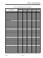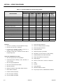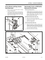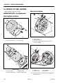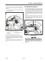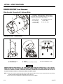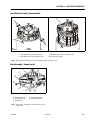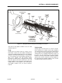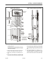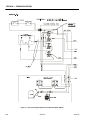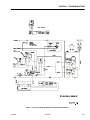
1
Service and Maintenance Manual
Model
12SP
15SP
3120775
March 17, 2008
NOTES:
FOREWORD
The purpose of this manual is to provide users with the operating procedures essential for the promotion of
proper machine operation for its intended purpose. It is important to over-stress proper machine usage. All
information in this manual should be READ and UNDERSTOOD before any attempt is made to operate the
machine. YOUR OPERATING MANUAL IS YOUR MOST IMPORTANT TOOL - Keep it with the machine.
REMEMBER ANY EQUIPMENT IS ONLY AS SAFE AS THE OPERATOR.
BECAUSE THE MANUFACTURER HAS NO DIRECT CONTROL OVER MACHINE APPLICATION AND
OPERATION, PROPER SAFETY PRACTICES ARE THE RESPONSIBILITY OF THE USER AND HIS OPERATING PERSONNEL.
ALL INSTRUCTIONS IN THIS MANUAL ARE BASED ON THE USE OF THE MACHINE UNDER PROPER
OPERATING CONDITIONS, WITH NO DEVIATIONS FROM THE ORIGINAL DESIGN. ALTERATION AND/
OR MODIFICATION OF THE MACHINE IS STRICTLY FORBIDDEN, WITHOUT WRITTEN APPROVAL
FROM JLG INDUSTRIES, PER OSHA REGULATIONS.
THIS "SAFETY ALERT SYMBOL" IS USED TO CALL ATTENTION TO POTENTIAL HAZARDS
WHICH MAY LEAD TO SERIOUS INJURY OR DEATH IF IGNORED.
Safety of personnel and proper use of the machine are of primary concern, DANGER, WARNING, CAUTION,
NOTICE, INSTRUCTIONS and NOTE are inserted throughout this manual to emphasize these areas. They
are defined as follows:
DANGER INDICATES AN IMMINENTLY HAZARDOUS SITUATION WHICH, IF NOT AVOIDED WILL RESULT IN SERIOUS
INJURY OR DEATH.
WARNING INDICATES A POTENTIALLY HAZARDOUS SITUATION WHICH, IF NOT AVOIDED COULD RESULT IN SERIOUS INJURY OR DEATH.
CAUTION INDICATES A POTENTIALLY HAZARDOUS SITUATION WHICH, IF NOT AVOIDED, MAY RESULT IN MINOR OR
MODERATE INJURY. IT MAY ALSO BE USED TO ALERT
AGAINST UNSAFE PRACTICES.
IMPORTANT OR INSTRUCTIONS PROCEDURES ESSENTIAL
FOR SAFE OPERATION AND WHICH, IF NOT FOLLOWED
MAY RESULT IN A MALFUNCTION OR DAMAGE TO THE
MACHINE.
Also in this Manual "Notes:" are used to provide information of special interest.
JLG INDUSTRIES, INC. MAY HAVE ISSUED SAFETY RELATED BULLETINS FOR YOUR JLG PRODUCT. CONTACT JLG INDUSTRIES, INC. OR THE LOCAL AUTHORIZED JLG DISTRIBUTOR FOR INFORMATION CONCERNING SAFETY RELATED BULLETINS WHICH MAY HAVE BEEN ISSUED FOR YOUR JLG PRODUCT. ALL ITEMS REQUIRED BY THE SAFETY RELATED
BULLETINS MUST BE COMPLETED ON THE AFFECTED JLG PRODUCT.
Due to the continuous product improvements, JLG Industries, Inc. reserves the right to make specification changes without
prior notification. Contact JLG Industries, Inc. for updated information.
NOTES:
MAINTENANCE SAFETY PRECAUTIONS
MAINTENANCE SAFETY PRECAUTIONS
GENERAL
HYDRAULIC SYSTEM SAFETY
This section contains the general safety precautions
which must be observed during maintenance of the aerial
platform. It is of utmost importance that maintenance personnel pay strict attention to these warnings and precautions to avoid possible injury to themselves or others or
damage to the equipment. A maintenance program must
be established by a qualified person and must be followed
to ensure that the machine is safe to operate.
MODIFICATION OF THE MACHINE WITHOUT CERTIFICATION BY
A RESPONSIBLE AUTHORITY THAT THE MACHINE IS AT LEAST
AS SAFE AS ORIGINALLY MANUFACTURED IS A SAFETY VIOLATION.
The specific precautions to be observed during machine
maintenance are inserted at the appropriate point in the
manual. These precautions are, for the most part, those
that apply when servicing hydraulic and larger machine
component parts.
Your safety, and that of others, is the first consideration
when engaging in the maintenance of equipment. Always
be conscious of component weight and never attempt to
move heavy parts without the aid of a mechanical device.
Do not allow heavy objects to rest in an unstable position.
When raising a portion of the equipment, ensure that adequate support is provided.
SINCE THE MACHINE MANUFACTURER HAS NO DIRECT CONTROL OVER THE FIELD INSPECTION AND MAINTENANCE,
SAFETY IN THIS AREA IS THE RESPONSIBILITY OF THE OWNER/
OPERATOR.
1. It should be particularly noted that the machines
hydraulic systems operate at extremely high and
potentially dangerous pressures. Every effort should
be made to relieve any system pressure prior to disconnecting or removing any portion of the system.
2. Relieve system pressure by activating the lift DOWN
control with the platform completely lowered to
direct any line pressure back into the return line to
the reservoir. Pressure feed lines to system components can then be disconnected with minimal fluid
loss.
MAINTENANCE
FAILURE TO COMPLY WITH SAFETY PRECAUTIONS LISTED IN
THIS SECTION COULD RESULT IN MACHINE DAMAGE, PERSONNEL INJURY OR DEATH AND IS A SAFETY VIOLATION.
• REMOVE ALL RINGS, WATCHES, AND JEWELRY
WHEN PERFORMING ANY MAINTENANCE.
• DO NOT WEAR LONG HAIR UNRESTRAINED, OR
LOOSE FITTING CLOTHING AND NECKTIES WHICH
ARE APT TO BECOME CAUGHT ON OR ENTANGLED
IN EQUIPMENT.
• OBSERVE AND OBEY ALL DANGER, WARNING, CAUTION AND OTHER INSTRUCTIONS ON MACHINE AND
IN SERVICE MANUAL.
• KEEP STANDING SURFACES AND HAND HOLDS
FREE OF OIL, GREASE, WATER, ETC.
• NEVER WORK UNDER AN ELEVATED PLATFORM
UNTIL PLATFORM HAS BEEN SAFELY RESTRAINED
FROM ANY MOVEMENT BY BLOCKING OR OVERHEAD SLING.
• BEFORE MAKING ADJUSTMENTS, LUBRICATING OR
PERFORMING ANY OTHER MAINTENANCE, SHUT
OFF ALL POWER CONTROLS.
• BATTERY SHOULD ALWAYS BE DISCONNECTED
DURING REPLACEMENT OF ELECTRICAL COMPONENTS.
• KEEP ALL SUPPORT EQUIPMENT AND ATTACHMENTS STOWED IN THEIR PROPER PLACE.
• USE ONLY APPROVED, NONFLAMMABLE CLEANING
SOLVENTS.
3120775
– JLG Lift –
a
EFFECTIVITY PAGE
EFFECTIVITY CHANGES
June 2, 1999 - Original Issue of Manual
March 7, 2000 - Manual Revised (added CSA/Latin America Specifications)
April 13, 2000 - Manual Revised (added 12SP Model)
April 25, 2000 - Manual Revised (corrected Mast Disassembly/Assembly - Section-2.)
November 22, 2000 - Manual Revised - Pages Affected;Section 2 - Pages 2-4 through 2-19.
January 25, 2001 - Manual Revised - Pages Affected;Section 2 - Page 2-14 and 2-15.
January 16, 2002 – Manual Revised
January 20, 2006 – Manual Revised
July 10, 2006 – Manual Revised
March 17, 2008 – Manual Revised
b
– JLG Lift –
3120775
TABLE OF CONTENTS
SUBJECT - SECTION, PARAGRAPH
PAGE NO.
MAINTENANCE SAFETY PRECAUTIONS. . . . . . . . . . . . . . . . . . . . . . . . . . . . . . . . . . . . . . . . . . . . . . . . . .a
General . . . . . . . . . . . . . . . . . . . . . . . . . . . . . . . . . . . . . . . . . . . . . . . . . . . . . . . . . . . . . . . . . . . . .a
Hydraulic System Safety . . . . . . . . . . . . . . . . . . . . . . . . . . . . . . . . . . . . . . . . . . . . . . . . . . . . . . . .a
Maintenance . . . . . . . . . . . . . . . . . . . . . . . . . . . . . . . . . . . . . . . . . . . . . . . . . . . . . . . . . . . . . . . . .a
EFFECTIVITY CHANGES. . . . . . . . . . . . . . . . . . . . . . . . . . . . . . . . . . . . . . . . . . . . . . . . . . . . . . . . . . . . . . .b
SECTION 1 - SPECIFICATIONS
1.1
1.2
1.3
1.4
1.5
1.6
1.7
1.8
CAPACITIES . . . . . . . . . . . . . . . . . . . . . . . . . . . . . . . . . . . . . . . . . . . . . . . . . . . . . . . . . . . . . . .
Hydraulic Oil Reservoir . . . . . . . . . . . . . . . . . . . . . . . . . . . . . . . . . . . . . . . . . . . . . . . . . . .
COMPONENT DATA . . . . . . . . . . . . . . . . . . . . . . . . . . . . . . . . . . . . . . . . . . . . . . . . . . . . . . . . .
Hydraulic Pump/Electric Motor Assembly. . . . . . . . . . . . . . . . . . . . . . . . . . . . . . . . . . . . .
Batteries . . . . . . . . . . . . . . . . . . . . . . . . . . . . . . . . . . . . . . . . . . . . . . . . . . . . . . . . . . . . . . .
Battery Charger . . . . . . . . . . . . . . . . . . . . . . . . . . . . . . . . . . . . . . . . . . . . . . . . . . . . . . . . .
PERFORMANCE DATA . . . . . . . . . . . . . . . . . . . . . . . . . . . . . . . . . . . . . . . . . . . . . . . . . . . . . . .
Platform Capacity (Max. Rated Load) . . . . . . . . . . . . . . . . . . . . . . . . . . . . . . . . . . . . . . . .
Machine Speeds . . . . . . . . . . . . . . . . . . . . . . . . . . . . . . . . . . . . . . . . . . . . . . . . . . . . . . . .
Machine Weight (With Standard Platform) . . . . . . . . . . . . . . . . . . . . . . . . . . . . . . . . . . . .
Machine Height (Platform Stowed) . . . . . . . . . . . . . . . . . . . . . . . . . . . . . . . . . . . . . . . . . .
Maximum Platform Height (Mast Fully Extended). . . . . . . . . . . . . . . . . . . . . . . . . . . . . . .
Maximum Working Height (Average Person) . . . . . . . . . . . . . . . . . . . . . . . . . . . . . . . . . .
Machine Overall Width And Length (Stowed) . . . . . . . . . . . . . . . . . . . . . . . . . . . . . . . . . .
TORQUE REQUIREMENTS. . . . . . . . . . . . . . . . . . . . . . . . . . . . . . . . . . . . . . . . . . . . . . . . . . . .
LUBRICATION . . . . . . . . . . . . . . . . . . . . . . . . . . . . . . . . . . . . . . . . . . . . . . . . . . . . . . . . . . . . . .
Hydraulic Oil . . . . . . . . . . . . . . . . . . . . . . . . . . . . . . . . . . . . . . . . . . . . . . . . . . . . . . . . . . .
Lubrication Specifications . . . . . . . . . . . . . . . . . . . . . . . . . . . . . . . . . . . . . . . . . . . . . . . . .
HYDRAULIC PRESSURE ADJUSTMENT . . . . . . . . . . . . . . . . . . . . . . . . . . . . . . . . . . . . . . . . .
CYLINDER SPECIFICATIONS . . . . . . . . . . . . . . . . . . . . . . . . . . . . . . . . . . . . . . . . . . . . . . . . . .
SERIAL NUMBER LOCATIONS. . . . . . . . . . . . . . . . . . . . . . . . . . . . . . . . . . . . . . . . . . . . . . . . .
1-1
1-1
1-1
1-1
1-1
1-1
1-1
1-1
1-1
1-1
1-1
1-1
1-1
1-1
1-1
1-2
1-2
1-2
1-2
1-2
1-2
SECTION 2 - SERVICE PROCEDURES
2.1
2.2
2.3
3120775
MACHINE PREPARATION, INSPECTION, AND MAINTENANCE. . . . . . . . . . . . . . . . . . . . . . . 2-1
General. . . . . . . . . . . . . . . . . . . . . . . . . . . . . . . . . . . . . . . . . . . . . . . . . . . . . . . . . . . . . . . . 2-1
Preparation, Inspection, and Maintenance . . . . . . . . . . . . . . . . . . . . . . . . . . . . . . . . . . . . 2-1
Pre-Start Inspection . . . . . . . . . . . . . . . . . . . . . . . . . . . . . . . . . . . . . . . . . . . . . . . . . . . . . . 2-1
Pre-Delivery Inspection and Frequent Inspection . . . . . . . . . . . . . . . . . . . . . . . . . . . . . . . 2-1
Annual Machine Inspection . . . . . . . . . . . . . . . . . . . . . . . . . . . . . . . . . . . . . . . . . . . . . . . . 2-1
Preventative Maintenance . . . . . . . . . . . . . . . . . . . . . . . . . . . . . . . . . . . . . . . . . . . . . . . . . 2-1
PREVENTIVE MAINTENANCE AND INSPECTION SCHEDULE. . . . . . . . . . . . . . . . . . . . . . . . 2-2
SERVICING AND MAINTENANCE GUIDELINES . . . . . . . . . . . . . . . . . . . . . . . . . . . . . . . . . . . 2-4
General. . . . . . . . . . . . . . . . . . . . . . . . . . . . . . . . . . . . . . . . . . . . . . . . . . . . . . . . . . . . . . . . 2-4
Safety and Workmanship . . . . . . . . . . . . . . . . . . . . . . . . . . . . . . . . . . . . . . . . . . . . . . . . . 2-4
Cleanliness. . . . . . . . . . . . . . . . . . . . . . . . . . . . . . . . . . . . . . . . . . . . . . . . . . . . . . . . . . . . . 2-4
Components Removal and Installation . . . . . . . . . . . . . . . . . . . . . . . . . . . . . . . . . . . . . . . 2-4
Component Disassembly and Reassembly . . . . . . . . . . . . . . . . . . . . . . . . . . . . . . . . . . . 2-4
Pressure-Fit Parts. . . . . . . . . . . . . . . . . . . . . . . . . . . . . . . . . . . . . . . . . . . . . . . . . . . . . . . . 2-4
Bearings . . . . . . . . . . . . . . . . . . . . . . . . . . . . . . . . . . . . . . . . . . . . . . . . . . . . . . . . . . . . . . . 2-4
Gaskets . . . . . . . . . . . . . . . . . . . . . . . . . . . . . . . . . . . . . . . . . . . . . . . . . . . . . . . . . . . . . . . 2-4
Bolt Usage and Torque Application . . . . . . . . . . . . . . . . . . . . . . . . . . . . . . . . . . . . . . . . . 2-5
Hydraulic Lines and Electrical Wiring . . . . . . . . . . . . . . . . . . . . . . . . . . . . . . . . . . . . . . . . 2-5
Hydraulic System. . . . . . . . . . . . . . . . . . . . . . . . . . . . . . . . . . . . . . . . . . . . . . . . . . . . . . . . 2-5
Lubrication and Servicing . . . . . . . . . . . . . . . . . . . . . . . . . . . . . . . . . . . . . . . . . . . . . . . . . 2-5
Batteries . . . . . . . . . . . . . . . . . . . . . . . . . . . . . . . . . . . . . . . . . . . . . . . . . . . . . . . . . . . . . . . 2-5
Mast Chain Inspection Procedure . . . . . . . . . . . . . . . . . . . . . . . . . . . . . . . . . . . . . . . . . . . 2-5
Mast Cable Inspection Procedure . . . . . . . . . . . . . . . . . . . . . . . . . . . . . . . . . . . . . . . . . . . 2-6
– JLG Lift –
i
TABLE OF CONTENTS
2.4
2.5
2.6
2.7
2.8
2.9
2.10
2.11
2.12
ii
LUBRICATION INFORMATION . . . . . . . . . . . . . . . . . . . . . . . . . . . . . . . . . . . . . . . . . . . . . . . . . 2-7
Hydraulic System. . . . . . . . . . . . . . . . . . . . . . . . . . . . . . . . . . . . . . . . . . . . . . . . . . . . . . . . 2-7
Hydraulic Oil . . . . . . . . . . . . . . . . . . . . . . . . . . . . . . . . . . . . . . . . . . . . . . . . . . . . . . . . . . . 2-7
Changing Hydraulic Oil . . . . . . . . . . . . . . . . . . . . . . . . . . . . . . . . . . . . . . . . . . . . . . . . . . . 2-7
Lubrication Specifications . . . . . . . . . . . . . . . . . . . . . . . . . . . . . . . . . . . . . . . . . . . . . . . . . 2-7
BATTERY CHARGER - ASSEMBLY AND DISASSEMBLY . . . . . . . . . . . . . . . . . . . . . . . . . . . . 2-8
General Information . . . . . . . . . . . . . . . . . . . . . . . . . . . . . . . . . . . . . . . . . . . . . . . . . . . . . . 2-8
Battery Charger Removal . . . . . . . . . . . . . . . . . . . . . . . . . . . . . . . . . . . . . . . . . . . . . . . . . 2-8
Cover Removal . . . . . . . . . . . . . . . . . . . . . . . . . . . . . . . . . . . . . . . . . . . . . . . . . . . . . . . . . 2-8
Transformer Replacement . . . . . . . . . . . . . . . . . . . . . . . . . . . . . . . . . . . . . . . . . . . . . . . . . 2-9
Printed Circuit Board Replacement. . . . . . . . . . . . . . . . . . . . . . . . . . . . . . . . . . . . . . . . . . 2-9
DC Circuit Breaker Replacement . . . . . . . . . . . . . . . . . . . . . . . . . . . . . . . . . . . . . . . . . . . 2-9
AC Circuit Breaker and Voltage Selection Switch Replacement . . . . . . . . . . . . . . . . . . 2-10
Shunt Assembly, Varistor, and SCR Rectifier Replacement (See Illustration) . . . . . . . . 2-10
HYDRAULIC LIFT PUMP - SERVICING . . . . . . . . . . . . . . . . . . . . . . . . . . . . . . . . . . . . . . . . . . 2-11
FENNER BRAND PUMP - Brush Replacement . . . . . . . . . . . . . . . . . . . . . . . . . . . . . . . . 2-11
Motor Cap/Motor Installation . . . . . . . . . . . . . . . . . . . . . . . . . . . . . . . . . . . . . . . . . . . . . . 2-11
Motor Brush Installation. . . . . . . . . . . . . . . . . . . . . . . . . . . . . . . . . . . . . . . . . . . . . . . . . . 2-11
Brush Housing Final Assembly Tips . . . . . . . . . . . . . . . . . . . . . . . . . . . . . . . . . . . . . . . . 2-12
MONARCH BRAND PUMP - Brush Replacement . . . . . . . . . . . . . . . . . . . . . . . . . . . . . . 2-13
Motor Assembly - Remove/Install - Reference Marks . . . . . . . . . . . . . . . . . . . . . . . . . . . 2-13
Motor/Brush Cover - Remove/Install . . . . . . . . . . . . . . . . . . . . . . . . . . . . . . . . . . . . . . . . 2-13
Brush Carrier Assembly - Remove/Install . . . . . . . . . . . . . . . . . . . . . . . . . . . . . . . . . . . . 2-14
Brush Assembly - Remove/Install . . . . . . . . . . . . . . . . . . . . . . . . . . . . . . . . . . . . . . . . . . 2-14
TANK AND PUMP REMOVAL - (All Pumps) . . . . . . . . . . . . . . . . . . . . . . . . . . . . . . . . . . 2-15
Tank Installation. . . . . . . . . . . . . . . . . . . . . . . . . . . . . . . . . . . . . . . . . . . . . . . . . . . . . . . . 2-15
Filter Screen Installation . . . . . . . . . . . . . . . . . . . . . . . . . . . . . . . . . . . . . . . . . . . . . . . . . 2-15
Pump Installation . . . . . . . . . . . . . . . . . . . . . . . . . . . . . . . . . . . . . . . . . . . . . . . . . . . . . . . 2-15
Pressure Adjust Valve Installation . . . . . . . . . . . . . . . . . . . . . . . . . . . . . . . . . . . . . . . . . . 2-16
Pressure Check Valve Installation . . . . . . . . . . . . . . . . . . . . . . . . . . . . . . . . . . . . . . . . . . 2-16
HYDRAULIC LIFT CYLINDER - REMOVAL, INSPECTION AND REBUILD . . . . . . . . . . . . . . . 2-17
Cylinder Removal. . . . . . . . . . . . . . . . . . . . . . . . . . . . . . . . . . . . . . . . . . . . . . . . . . . . . . . 2-17
Cylinder Disassembly . . . . . . . . . . . . . . . . . . . . . . . . . . . . . . . . . . . . . . . . . . . . . . . . . . . 2-17
Lift Cylinder Component Inspection . . . . . . . . . . . . . . . . . . . . . . . . . . . . . . . . . . . . . . . . 2-17
Cylinder Assembly . . . . . . . . . . . . . . . . . . . . . . . . . . . . . . . . . . . . . . . . . . . . . . . . . . . . . . 2-19
Installation . . . . . . . . . . . . . . . . . . . . . . . . . . . . . . . . . . . . . . . . . . . . . . . . . . . . . . . . . . . . 2-19
MAST ASSEMBLY AND DISASSEMBLY PROCEDURES . . . . . . . . . . . . . . . . . . . . . . . . . . . . 2-20
Mast Disassembly Procedure . . . . . . . . . . . . . . . . . . . . . . . . . . . . . . . . . . . . . . . . . . . . . 2-20
Platform Section Removal . . . . . . . . . . . . . . . . . . . . . . . . . . . . . . . . . . . . . . . . . . . . . . . . 2-20
Mast Section 4 Removal . . . . . . . . . . . . . . . . . . . . . . . . . . . . . . . . . . . . . . . . . . . . . . . . . 2-21
Mast Section 3 Removal . . . . . . . . . . . . . . . . . . . . . . . . . . . . . . . . . . . . . . . . . . . . . . . . . 2-21
Mast Section 2 Removal . . . . . . . . . . . . . . . . . . . . . . . . . . . . . . . . . . . . . . . . . . . . . . . . . 2-21
Mast Section 1 Disassembly (All Masts) . . . . . . . . . . . . . . . . . . . . . . . . . . . . . . . . . . . . . 2-21
MAST ASSEMBLY . . . . . . . . . . . . . . . . . . . . . . . . . . . . . . . . . . . . . . . . . . . . . . . . . . . . . . . . . . 2-22
Mast Section 1 - Assembly . . . . . . . . . . . . . . . . . . . . . . . . . . . . . . . . . . . . . . . . . . . . . . . 2-22
Mast Section 2 - Assembly . . . . . . . . . . . . . . . . . . . . . . . . . . . . . . . . . . . . . . . . . . . . . . . 2-22
Mast Section 3 - Assembly . . . . . . . . . . . . . . . . . . . . . . . . . . . . . . . . . . . . . . . . . . . . . . . 2-26
Mast Section 4 - Assembly . . . . . . . . . . . . . . . . . . . . . . . . . . . . . . . . . . . . . . . . . . . . . . . 2-27
Platform Mounting Section - Assembly . . . . . . . . . . . . . . . . . . . . . . . . . . . . . . . . . . . . . . 2-28
MAST TO BASE FRAME INSTALLATION . . . . . . . . . . . . . . . . . . . . . . . . . . . . . . . . . . . . . . . . 2-28
MAST CHAINS/CABLES AND SEQUENCING CABLES ADJUSTMENT . . . . . . . . . . . . . . . . 2-29
Mast Chain/Cable Adjustment. . . . . . . . . . . . . . . . . . . . . . . . . . . . . . . . . . . . . . . . . . . . . 2-29
Sequencing Cable Adjustment . . . . . . . . . . . . . . . . . . . . . . . . . . . . . . . . . . . . . . . . . . . . 2-31
SEQUENCE CABLE REPLACEMENT KIT. . . . . . . . . . . . . . . . . . . . . . . . . . . . . . . . . . . . . . . . 2-31
Remove Old Cable. . . . . . . . . . . . . . . . . . . . . . . . . . . . . . . . . . . . . . . . . . . . . . . . . . . . . . 2-31
Replacement Cable Installation. . . . . . . . . . . . . . . . . . . . . . . . . . . . . . . . . . . . . . . . . . . . 2-31
Clamp Installation (Drum/Socket Type) . . . . . . . . . . . . . . . . . . . . . . . . . . . . . . . . . . . . . 2-32
– JLG Lift –
3120775
TABLE OF CONTENTS
SECTION 3 - TROUBLESHOOTING
3.1
3.2
3.3
3.4
3.5
General . . . . . . . . . . . . . . . . . . . . . . . . . . . . . . . . . . . . . . . . . . . . . . . . . . . . . . . . . . . . . . . . . . .
Troubleshooting Information. . . . . . . . . . . . . . . . . . . . . . . . . . . . . . . . . . . . . . . . . . . . . . . . . . .
Hydraulic Circuit Checks. . . . . . . . . . . . . . . . . . . . . . . . . . . . . . . . . . . . . . . . . . . . . . . . . . . . . .
ELECTRICAL SYSTEM - MULTIMETER BASICS . . . . . . . . . . . . . . . . . . . . . . . . . . . . . . . . . . .
Grounding . . . . . . . . . . . . . . . . . . . . . . . . . . . . . . . . . . . . . . . . . . . . . . . . . . . . . . . . . . . . .
Backprobing . . . . . . . . . . . . . . . . . . . . . . . . . . . . . . . . . . . . . . . . . . . . . . . . . . . . . . . . . . .
Min/Max . . . . . . . . . . . . . . . . . . . . . . . . . . . . . . . . . . . . . . . . . . . . . . . . . . . . . . . . . . . . . . .
Polarity . . . . . . . . . . . . . . . . . . . . . . . . . . . . . . . . . . . . . . . . . . . . . . . . . . . . . . . . . . . . . . . .
Scale . . . . . . . . . . . . . . . . . . . . . . . . . . . . . . . . . . . . . . . . . . . . . . . . . . . . . . . . . . . . . . . . .
Continuity Measurement Over Long Distances . . . . . . . . . . . . . . . . . . . . . . . . . . . . . . . .
Requirements: . . . . . . . . . . . . . . . . . . . . . . . . . . . . . . . . . . . . . . . . . . . . . . . . . . . . . . . . . .
Procedure . . . . . . . . . . . . . . . . . . . . . . . . . . . . . . . . . . . . . . . . . . . . . . . . . . . . . . . . . . . . .
ELECTRICAL SWITCH TESTING . . . . . . . . . . . . . . . . . . . . . . . . . . . . . . . . . . . . . . . . . . . . . . .
Basic Check . . . . . . . . . . . . . . . . . . . . . . . . . . . . . . . . . . . . . . . . . . . . . . . . . . . . . . . . . . . .
Limit Switches . . . . . . . . . . . . . . . . . . . . . . . . . . . . . . . . . . . . . . . . . . . . . . . . . . . . . . . . . .
Automatic Switches . . . . . . . . . . . . . . . . . . . . . . . . . . . . . . . . . . . . . . . . . . . . . . . . . . . . . .
Switch Wiring - Low Side, High Side . . . . . . . . . . . . . . . . . . . . . . . . . . . . . . . . . . . . . . . . .
3-1
3-1
3-1
3-1
3-1
3-1
3-1
3-2
3-2
3-2
3-2
3-2
3-5
3-5
3-5
3-5
3-5
LIST OF FIGURES
FIGURE NO.
1-1.
1-2.
2-1.
2-2.
2-3.
2-4.
2-5.
2-6.
3-1.
3-2.
3-3.
3-4.
3-5.
3-6.
3-7.
TITLE
PAGE NO.
Hydraulic Pressure Setting - Adjustment Screw Located at Base of Pump Motor . . . . . . . . . 1-2
Torque Chart. . . . . . . . . . . . . . . . . . . . . . . . . . . . . . . . . . . . . . . . . . . . . . . . . . . . . . . . . . . . . . . 1-4
Lift Cylinder Internal Component Assembly Cross-Section. . . . . . . . . . . . . . . . . . . . . . . . . . 2-18
Mast Section - Assembly/Disassembly Reference. . . . . . . . . . . . . . . . . . . . . . . . . . . . . . . . . 2-20
15SP Mast Assembly Components. (5 Section). . . . . . . . . . . . . . . . . . . . . . . . . . . . . . . . . . . 2-23
12SP Mast Assembly Components. (4 Section). . . . . . . . . . . . . . . . . . . . . . . . . . . . . . . . . . . 2-24
Mast Chain Routing Diagram. . . . . . . . . . . . . . . . . . . . . . . . . . . . . . . . . . . . . . . . . . . . . . . . . . 2-25
Mast Chain/Cable/Sequence Cable Adjustment Components. (Typical) . . . . . . . . . . . . . . . 2-30
Voltage Measurement (DC). . . . . . . . . . . . . . . . . . . . . . . . . . . . . . . . . . . . . . . . . . . . . . . . . . . . 3-3
Resistance Measurement . . . . . . . . . . . . . . . . . . . . . . . . . . . . . . . . . . . . . . . . . . . . . . . . . . . . . 3-3
Continuity Measurement . . . . . . . . . . . . . . . . . . . . . . . . . . . . . . . . . . . . . . . . . . . . . . . . . . . . . . 3-4
Current Measurement (DC). . . . . . . . . . . . . . . . . . . . . . . . . . . . . . . . . . . . . . . . . . . . . . . . . . . . 3-4
Hydraulic Schematic. (SP Series) . . . . . . . . . . . . . . . . . . . . . . . . . . . . . . . . . . . . . . . . . . . . . . . 3-7
Electrical Diagram (Standard). . . . . . . . . . . . . . . . . . . . . . . . . . . . . . . . . . . . . . . . . . . . . . . . . . 3-8
Electrical Diagram (With Floor Brake/Gate Alarm Option) . . . . . . . . . . . . . . . . . . . . . . . . . . . 3-10
LIST OF TABLES
TABLE NO.
1-1
1-2
1-3
1-4
2-1
2-2
2-3
2-4
3-1.
3120775
TITLE
PAGE NO.
Hydraulic Oil Operating Range . . . . . . . . . . . . . . . . . . . . . . . . . . . . . . . . . . . . . . . . . . . . . . . . . 1-2
Lubrication Specifications . . . . . . . . . . . . . . . . . . . . . . . . . . . . . . . . . . . . . . . . . . . . . . . . . . . . . 1-2
Cylinder Specifications . . . . . . . . . . . . . . . . . . . . . . . . . . . . . . . . . . . . . . . . . . . . . . . . . . . . . . . 1-2
Lubrication Intervals for Various Components . . . . . . . . . . . . . . . . . . . . . . . . . . . . . . . . . . . . . 1-3
Inspection and Maintenance . . . . . . . . . . . . . . . . . . . . . . . . . . . . . . . . . . . . . . . . . . . . . . . . . . . 2-2
Preventive Maintenance & Inspection Schedule . . . . . . . . . . . . . . . . . . . . . . . . . . . . . . . . . . . 2-3
Chain Stretch Tolerance . . . . . . . . . . . . . . . . . . . . . . . . . . . . . . . . . . . . . . . . . . . . . . . . . . . . . . 2-5
AM Series Mast Component Features . . . . . . . . . . . . . . . . . . . . . . . . . . . . . . . . . . . . . . . . . . 2-20
DC Unit - Troubleshooting . . . . . . . . . . . . . . . . . . . . . . . . . . . . . . . . . . . . . . . . . . . . . . . . . . . . 3-6
– JLG Lift –
iii
TABLE OF CONTENTS
NOTES:
iv
– JLG Lift –
3120775
SECTION 1 - SPECIFICATIONS
SECTION 1. SPECIFICATIONS
1.1 CAPACITIES
1.3 PERFORMANCE DATA
Hydraulic Oil Reservoir
Platform Capacity (Max. Rated Load)
DC Models - 5 qts. U.S. (4.7 ltr.)
12SP & 15SP - 500 lb.* (227kg) - ANSI-U.S.A./
Latin America
1.2 COMPONENT DATA
12SP & 15SP - 400 lb.* (181kg) - CSA - Canada
Hydraulic Pump/Electric Motor Assembly
* Evenly distributed on platform floor.
* Extendible Platform - Max. 250 lb. on rear/250 lb. on
front, when extended. Not Available for CSA.
DC MODELS - 12 VOLT DC MOTOR/PUMP
Machine Speeds
Motor - 12v - DC Standard Duty
Pump Displacement - .098 cu. in./rev.(AFC 1.6 cc/rev.)
12SP - Lift up - 25 seconds *
Lift down - 13 to 20 seconds *
Pump Output - 1.42 GPM @ 800 PSI @ 11.7v-DC @
15SP - Lift up - 30 seconds *
Lift down - 18 to 25 seconds *
135 AMPS @ 45 Centistrokes (200 SSU)
Pressure Relief - Adjustable Range 1500 to 5000 PSI,
Set to 2800 PSI (193 bar) at factory
* Timed with maximum rated load: 500 lb.
Machine Weight (With Standard Platform)
Batteries
12SP - 1,180 lbs. (535 kg)
WET (Standard)
15SP - 1,240 lbs. (563 kg)
12 Volt - 165 Amp (min.) - Deep Cycle Marine - RV
Machine Height (Platform Stowed)
DRY (Option)
12SP & 15SP - 78 in. (1.9 m)
12 Volt - 165 Amp (min.) - Deep Cycle Marine - RV
Maximum Platform Height (Mast Fully Extended)
AGM (Absorption Gas Mat) (Option)
12SP - 11 ft. 7 in. (3.53 m)
12Volt - 100 O.A.H. - M2 Marine Combination
15SP - 15 ft. 2 in. (4.62 m)
Battery Charger
Maximum Working Height (Average Person)
110/240 Volts AC, 50/60 Hz - input
12SP - 18 ft. (5.4 m)
12 Volt DC, 10 Amp - output
15SP - 21 ft. (6.4 m)
Automatic SCR Charger
Machine Overall Width And Length (Stowed)
Selectable Voltage
12SP - 34 in.(W) x 73 in.(L) (86 cm x 185 cm)
NOTE: A high output - 12Volt DC, 20 Amp output - SCR
charger is supplied with the AGM battery option.
15SP - 34 in.(W) x 75.5 in.(L) (86 cm x 192 cm)
(Length includes platform and battery pack, end to end.)
1.4 TORQUE REQUIREMENTS
When maintenance becomes necessary or a fastener has
loosened, refer to the Torque Chart, Table 1-2. to determine proper torque value.
3120775
– JLG Lift –
1-1
SECTION 1 - SPECIFICATIONS
1.5 LUBRICATION
Hydraulic Oil
Hydraulic oils must have anti-wear qualities at least to API
Service Classification GL-3, and sufficient chemical stability for mobile hydraulic system service. JLG Industries,
recommends Mobilfluid 424 hydraulic oil, which has an
SAE viscosity of 10W-30 and a viscosity index of 152.
Do not adjust system pressure higher than required to
raise maximum rated load capacity. Make pressure adjustment with oil at normal operating temperature. If pressure
is set when oil is cold, platform may not raise rated load
after oil has warmed.
For cold weather applications, i.e. when temperatures
remain consistently below +20°F (–7°C) JLG recommends using Mobil DTE 13 hydraulic oil.
Aside from JLG recommendations, it is not advisable to
mix oils of different brands or types, as they may not contain the same required additives or be of comparable viscosities. If use of hydraulic oil other than Mobilfluid 424 is
desired, contact JLG Industries for proper recommendations.
PRESSURE
ADJUSTMENT
SCREW
ADJUSTMENT
SCREW CAP
(SHOWN REMOVED)
HYDRAULIC
OIL TANK
Table 1-1. Hydraulic Oil Operating Range
HYDRAULIC SYSTEM OPERATING
TEMPERATURE RANGE
SAE VISCOSITY
GRADE
+0˚ F to +180˚ F
(-18˚ C to +83˚ C)
10W
+0˚ F to +210˚ F
(-18˚ C to +99˚ C)
10W-20, 10W-30
+50˚ F to +210˚ F
(+10˚ C to +99˚ C)
20W-20
GROUND
CONTROL
STATION
COVER
Figure 1-1. Hydraulic Pressure Setting - Adjustment
Screw Located at Base of Pump Motor
(Remove Hex Head Cap as Shown)
Lubrication Specifications
1.7 CYLINDER SPECIFICATIONS
Table 1-2. Lubrication Specifications
KEY
SPECIFICATIONS
MPG -
Multipurpose Grease having a minimum dripping point
of 350° F. Excellent water resistance and adhesive qualities, and being of extreme pressure type. (Timken OK
40 pounds minimum.)
EPGL -
NOTE: All dimensions are given in inches (in), with the metric equivalent, centimeters (cm), given in parentheses.
Table 1-3. Cylinder Specifications
BORE
in./(cm)
STROKE
in./(cm)
ROD DIA.
in./(cm)
Lift Cylinder - 12SP
1.63
(4.1)
32.5
(82.5)
1.38
(3.5)
Lift Cylinder - 15SP
1.63
(4.1)
41.5
(105.4)
1.38
(3.5)
Extreme Pressure Gear Lube (oil) meeting API service
classification GL-5 or MIL-Spec MIL-L-2105.
HO -
Hydraulic Oil. ISO-Vg grade 32, 46.
CL -
Chain Lube. Use a good quality chain lubricant
DESCRIPTION
1.6 HYDRAULIC PRESSURE ADJUSTMENT
1.8 SERIAL NUMBER LOCATIONS
(See Table 1-1.)
Adjust system pressure so that platform will raise with
rated capacity in platform.
Turning adjustment screw clockwise, increases system
pressure, turning screw counterclockwise, decreases
system pressure.
1-2
For machine identification, a serial number plate is affixed
to the machine. The plate is located on the back of the
mast, just above the mast support bracket. In addition,
should the serial number plate be damaged or missing,
the machine serial is stamped on the mast and on the
base frame.
– JLG Lift –
3120775
SECTION 1 - SPECIFICATIONS
3
1
2
Table 1-4. Lubrication Intervals for Various Components
INTERVAL HOURS
ITEM
1
COMPONENT
Hydraulic Oil
NO/TYPE
LUBE POINTS
Fill To Line
on Reservoir
5 Qt. (4.3 L)
Reservoir
3 MOS.
or
150 Hrs.
LUBE/METHOD
HO - Check
Hyd. Oil Level
HO - Change
Hyd. Oil
1 YR.
or
600 Hrs.
2 YRS.
or
1200 Hrs.
✔
2
Swivel Raceways 2 - Front Casters
MPG - Pressure Gun
3
Mast Chains *
CL - Brush or Spray
2 - Per Section
6 MOS.
or
300 Hrs.
COMMENTS
Check Hyd. Oil after every
10 hrs. of operation.
Change Hyd. Oil after every 1200
hrs. of operation.
✔
✔
Inspect, lubricate if dry or rusting.
* Applies Only to Mast Sections with Chains.
Key to Lubricants: MPG - Multipurpose Grease
HO - Hydraulic Oil - ISO-Vg grade 32, 46
CL - Chain Lube. Use a good quality chain lubricant
Notes: 1. Be certain to lubricate like items on each side of the machine.
2. Recommended lubricating intervals are based on normal use. If machine is subjected to severe operating conditions,
such as a high number of cycles, location, corrosive/dirty environment, etc., user must adjust lubricating requirements accordingly.
3. Lubricating intervals are calculated on 50 hours of machine operation a week.
4. Prior to checking hydraulic oil level, operate machine through one complete cycle of lift function (full up and down). Failure to do so will
result in incorrect oil level reading on the hydraulic reservoir.
3120775
– JLG Lift –
1-3
SECTION 1 - SPECIFICATIONS
Figure 1-2. Torque Chart.
1-4
– JLG Lift –
3120775
SECTION 2 - SERVICE PROCEDURES
SECTION 2. SERVICE PROCEDURES
2.1 MACHINE PREPARATION, INSPECTION,
AND MAINTENANCE
General
This section provides the necessary information needed
by those personnel that are responsible to place the
machine in operation readiness and maintain its safe
operating condition. For maximum service life and safe
operation, ensure that all the necessary inspections and
maintenance have been completed before placing the
machine into service.
Preparation, Inspection, and Maintenance
It is important to establish and conform to a comprehensive inspection and preventive maintenance program.
The following table outlines the periodic machine inspections and maintenance recommended by JLG Industries,
Inc. Consult your national, regional, or local regulations
for further requirements for aerial work platforms. The frequency of inspections and maintenance must be
increased as environment, severity and frequency of
usage requires.
Pre-Start Inspection
It is the User’s or Operator’s primary responsibility to perform a Pre-Start Inspection of the machine prior to use
daily or at each change of operator. Reference the Operator’s and Safety Manual for completion procedures for the
Pre-Start Inspection. The Operator and Safety Manual
must be read in its entirety and understood prior to performing the Pre-Start Inspection.
Pre-Delivery Inspection and Frequent
Inspection
The Pre-Delivery Inspection and Frequent Inspection shall
be performed by a qualified JLG equipment mechanic.
JLG Industries, Inc. recognizes a qualified JLG equipment
mechanic as a person who, by possession of a recognized degree, certificate, extensive knowledge, training, or
experience, has successfully demonstrated the ability and
proficiency to service, repair, and maintain the subject
JLG product model.
The Pre-Delivery Inspection and Frequent Inspection procedures are performed in the same manner, but at different times. The Pre-Delivery Inspection shall be performed
prior to each sale, lease, or rental delivery. The Frequent
Inspection shall be accomplished for each machine in service for 3 months or 150 hours (whichever comes first);
out of service for a period of more than 3 months; or when
purchased used. The frequency of this inspection must be
3120775
increased as environment, severity and frequency of
usage requires.
Reference the JLG Pre-Delivery and Frequent Inspection
Form and the Inspection and Preventative Maintenance
Schedule for items requiring inspection during the performance of these inspections. Reference the appropriate
areas of this manual for servicing and maintenance procedures.
Annual Machine Inspection
The Annual Machine Inspection must be performed by a
qualified JLG equipment mechanic on an annual basis, no
later than thirteen (13) months from the date of the prior
Annual Machine Inspection. JLG Industries, Inc. recognizes a qualified JLG equipment mechanic as a person
who has successfully completed the JLG Service Training
School for the subject JLG product model. Reference the
machine Service and Maintenance Manual and appropriate JLG inspection form for performance of this inspection.
Reference the JLG Annual Machine Inspection Form and
the Inspection and Preventative Maintenance Schedule for
items requiring inspection during the performance of this
inspection. Reference the appropriate areas of this manual for servicing and maintenance procedures.
For the purpose of receiving safety-related bulletins, it is
important that JLG Industries, Inc. has updated ownership
information for each machine. When performing each
Annual Machine Inspection, notify JLG Industries, Inc. of
the current machine ownership.
Preventative Maintenance
In conjunction with the specified inspections, maintenance shall be performed by a qualified JLG equipment
mechanic. JLG Industries, Inc. recognizes a qualified JLG
equipment mechanic as a person who, by possession of a
recognized degree, certificate, extensive knowledge, training, or experience, has successfully demonstrated the
ability and proficiency to service, repair, and maintain the
subject JLG product model.
Reference Table 2-2, Preventive Maintenance & Inspection
Schedule., and the appropriate areas of this manual for
servicing and maintenance procedures. The frequency of
service and maintenance must be increased as environment, severity and frequency of usage requires.
– JLG Lift –
2-1
SECTION 2 - SERVICE PROCEDURES
Table 2-1. Inspection and Maintenance
TYPE
FREQUENCY
PRIMARY
RESPONSIBILITY
SERVICE
QUALIFICATION
REFERENCE
Pre-Start
Inspection
Prior to use each day; or
At each Operator change.
User or Operator
User or Operator
Operator and Safety Manual
Pre-Delivery
Inspection
Prior to each sale, lease, or
rental delivery.
Owner, Dealer, or User
Qualified JLG
Mechanic
Service and Maintenance Manual and applicable JLG inspection form.
Frequent
Inspection
In service for 3 months or 150 hours,
whichever comes first; or Out of service
for a period of more than 3 months; or Purchased used.
Owner, Dealer, or User
Qualified JLG
Mechanic
Service and Maintenance Manual and applicable JLG inspection form.
Annual
Machine
Inspection
Annually, no later than 13 months from the
date of the prior inspection.
Owner, Dealer, or User
Qualified JLG
Mechanic
Service and Maintenance Manual and applicable JLG inspection form.
Preventative
Maintenance
At intervals as specified in the Service and
Maintenance Manual.
Owner, Dealer, or User
Qualified JLG
Mechanic
Service and Maintenance Manual
2.2 PREVENTIVE MAINTENANCE AND
INSPECTION SCHEDULE
(See Table 2-2.)
The preventive maintenance and inspection checks are
listed and defined in the following table. This table is
divided into two basic parts, the “AREA” to be inspected
and the “INTERVAL” at which the inspection is to take
place. Under the “AREA” portion of the table, the various
systems along with the components that make up that
system are listed. The “INTERVAL” portion of the table is
divided into five columns representing the various inspection time periods. The numbers listed within the interval
column represent the applicable inspection code for
which that component is to be checked.
The checks and services listed in this schedule are not
intended to replace any local or regional regulations that
may pertain to this type of equipment nor should the lists
be considered as all inclusive. Variances in interval times
may occur due to climate and/or conditions and depending on the location and use of the machine.
2-2
– JLG Lift –
3120775
SECTION 2 - SERVICE PROCEDURES
Table 2-2. Preventive Maintenance & Inspection Schedule.
INTERVAL
AREA ON MACHINE
MAST ASSEMBLY
PRE-START (1)
INSPECTION
3 MONTH
PREVENTATIVE
MAINTENANCE
6 MONTH
PREVENTATIVE
MAINTENANCE
PRE-DELIVERY (2)
OR FREQUENT (3)
INSPECTION
2, 5
2, 5
14
3, 14
14, 25
3
1, 2, 3
7
Mast Sections
Chain Systems
Sequence Cable Systems
Covers or Shields
1
Sheave Systems
1, 2
Bearings
1, 2
1, 2
Slide Pads
PLATFORM ASSEMBLY
ANNUAL (4)
(YEARLY)
INSPECTION
1, 2
7
Platform and Material Tray
1
1
1, 2, 4
1, 2, 4
Gate
1, 5
1, 5
Floor
1, 2
1, 2
Lanyard Anchorage Point
1, 4
1, 4
1, 2
1, 2
2
2
1, 7
1, 7
Platform Controls
5, 6, 7
5, 6, 7
Ground Controls
5, 6
5, 6, 14
5
5
Guard Rails
CHASSIS ASSEMBLY
Front Caster Wheels
7
1, 2
14
Rear Wheel Assembly
Bubble Level
Floor Stop Assembly(s)
FUNCTIONS/CONTROLS
1, 3, 7
7
Function Control Locks, Guards, or Detents
Function Enable System
Emergency Stop Switches (Ground & Platform)
5
Function Limit or Cutout Switch Systems
5
Manual Descent or Auxiliary Power
5
5
9
18
POWER SYSTEM
Battery
19
Battery Charger
HYDRAULIC/ELECTRIC SYSTEM
5
9
Hydraulic Pump
1, 2, 9
1, 2, 5, 9
Hydraulic Cylinder
2, 7, 9
2, 9
Cylinder Attachment Pins and Pin Retainers
1, 2
1, 2
Hydraulic Hoses, Lines, and Fittings
1, 9
1, 9
Hydraulic Reservoir, Cap, and Breather
5, 7
5, 7
11
11
20
20
Hydraulic Filter
Hydraulic Fluid *
11
Electrical Connections
Instruments, Gauges, Switches, Lights, Horn
3120775
5
– JLG Lift –
2-3
SECTION 2 - SERVICE PROCEDURES
Table 2-2. Preventive Maintenance & Inspection Schedule.
INTERVAL
AREA ON MACHINE
PRE-START (1)
INSPECTION
3 MONTH
PREVENTATIVE
MAINTENANCE
6 MONTH
PREVENTATIVE
MAINTENANCE
PRE-DELIVERY (2)
OR FREQUENT (3)
INSPECTION
ANNUAL (4)
(YEARLY)
INSPECTION
GENERAL
Operator and Safety Manuals in Storage Box
21
21
21
ANSI and EMI Manuals/Handbooks Installed
21
21
21
Capacity Decals Installed, Secure, Legible
21
21
21
All Decals/Placards Installed, Secure, Legible
21
21
21
"Walk-Around" Inspection Performed
22
Annual Machine Inspection Due
21
No Unauthorized Modifications or Additions
21
21
All Relevant Safety Publications Incorporated
21
21, 22
General Structural Condition and Welds
2, 4
2, 4
All Fasteners, Pins, Shields, and Covers
1, 2
Grease and Lubricate to Specifications
Function Test of All Systems
22
22
22
22
Paint and Appearance
7
7
Stamp Inspection Date on Frame
22
Notify JLG of Machine Ownership
22
* Drain and Refill with fresh hydraulic fluid every two years.
Footnotes:
11. Check for proper fluid level.
1. Prior to use each day; or at each Operator change
12. Check for chafing and proper routing.
2. Prior to each sale, lease, or delivery
13. Check for proper tolerances.
3. In service for 3 months; or Out of service for 3
months or more; or Purchased used
14. Properly lubricated.
4. Annually, no later than 13 months from the date of
the prior inspection
15. Torqued to proper specification.
16. No gouges, excessive wear, or cords showing.
17. Properly inflated and seated around rim.
Inspection and Maintenance Codes:
18. Proper and authorized components.
1. Check for proper and secure installation.
19. Fully charged.
2. Visual inspection for damage, cracks, distortion, or
excessive wear.
20. No loose connections, corrosion, or abrasions.
3. Check for proper adjustment.
21. Verify.
4. Check for cracked or broken welds.
22. Perform.
5. Operates properly.
23. Sealed properly.
6. Returns to neutral or "off" position when released.
24. Overrides Platform controls.
7. Clean and free of debris.
25. Inspected per Service and Maintenance Manual.
8. Interlocks function properly.
9. Check for signs of leakage.
10. Decals installed and legible.
2-4
– JLG Lift –
3120775
SECTION 2 - SERVICE PROCEDURES
2.3 SERVICING AND MAINTENANCE
GUIDELINES
Components Removal and Installation
General
The following information is provided to assist you in the
use and application of servicing and maintenance procedures contained in this chapter.
WHEN AN ABNORMAL CONDITION IS NOTED AND PROCEDURES
CONTAINED HEREIN DO NOT SPECIFICALLY RELATE TO THE
NOTED IRREGULARITY, WORK SHOULD BE STOPPED AND
TECHNICALLY QUALIFIED GUIDANCE OBTAINED BEFORE WORK
IS RESUMED.
Safety and Workmanship
Your safety, and that of others, is the first consideration
when engaging in the maintenance of equipment. Always
be conscious of component weight. Never attempt to
move heavy parts without the aid of a mechanical device.
Do not allow heavy objects to rest in an unstable position.
When raising a portion of the equipment, ensure that adequate support is provided.
NEVER WORK UNDER AN ELEVATED PLATFORM UNTIL PLATFORM HAS BEEN SAFELY RESTRAINED FROM ANY MOVEMENT
BY BLOCKING OR OVERHEAD SLING.
Cleanliness
The most important single item in preserving the long service life of a machine is to keep dirt and foreign materials
out of the vital components. Precautions have been taken
to safeguard against this. Shields, covers, seals, and filters are provided to keep the wheel bearings, mast sections and oil supply clean; however, these items must be
maintained on a scheduled basis in order to function
properly.
At any time when oil lines are disconnected, clear adjacent areas as well as the openings and fittings themselves. As soon as a line or component is disconnected,
cap or cover all openings to prevent entry of foreign matter.
Clean and inspect all parts during servicing or maintenance, and assure that all passages and openings are
unobstructed. Cover all parts to keep them clean. Be sure
all parts are clean before they are installed. New parts
should remain in their containers until they are ready to be
used.
3120775
Use adjustable lifting devices, whenever possible, if
mechanical assistance is required. All slings (chains,
cables, etc.) should be parallel to each other and as near
perpendicular as possible to top of part being lifted.
Should it be necessary to remove a component on an
angle, keep in mind that the capacity of an eyebolt or similar bracket lessens, as the angle between the supporting
structure and the component becomes less than 90
degrees.
If a part resists removal, check to see whether all nuts,
bolts, cables, brackets, wiring, etc., have been removed
and that no adjacent parts are interfering.
Component Disassembly and Reassembly
When disassembling or reassembling a component, complete the procedural steps in sequence. Do not partially
disassemble or assemble one part, then start on another.
Always recheck your work to assure that nothing has been
overlooked. Do not make any adjustments, other than
those recommended, without obtaining proper approval.
Pressure-Fit Parts
When assembling pressure-fit parts, use an “anti-seize” or
molybdenum disulfide base compound to lubricate the
mating surface.
Bearings
When a bearing is removed, cover it to keep out dirt and
abrasives. Clean bearings in nonflammable cleaning solvent and allow to drip dry. Compressed air can be used
but do not spin the bearing.
Discard bearings if the races and balls (or rollers) are pitted, scored, or burned.
If bearing is found to be serviceable, apply a light coat of
oil and wrap it in clean (waxed) paper. Do not unwrap
reusable or new bearings until they are ready to install.
Lubricate new or used serviceable bearings before installation. When pressing a bearing into a retainer or bore,
apply pressure to the outer race. If the bearing is to be
installed on a shaft, apply pressure to the inner race.
Gaskets
Check that holes in gaskets align with openings in the
mating parts. If it becomes necessary to hand-fabricate a
gasket, use gasket material or stock of equivalent material
and thickness. Be sure to cut holes in the right location, as
blank gaskets can cause serious system damage.
– JLG Lift –
2-5
SECTION 2 - SERVICE PROCEDURES
Bolt Usage and Torque Application
Mast Chain Inspection Procedure
Use bolts of proper length. A bolt which is too long will
bottom before the head is tight against its related part. If a
bolt is too short, there will not be enough thread area to
engage and hold the part properly. When replacing bolts,
use only those having the same specifications of the original, or one which is equivalent.
Unless specific torque requirements are given within the
text, standard torque values should be used on heattreated bolts, studs, and steel nuts, in accordance with
recommended shop practices. (See Section-1, Torque
Charts)
Hydraulic Lines and Electrical Wiring
Clearly mark or tag hydraulic lines and electrical wiring, as
well as their receptacles, when disconnecting or removing
them from the unit. This will assure that they are correctly
reinstalled.
Inspect mast chains for the following conditions:
Wear: Always inspect that segment of chain that operates
over a sheave. As the chain flexes over the sheaves, joints
and plate edges very gradually wear. Chain “stretch” can
be measured using a manufacturers wear scale or steel
tape. When chains have elongated 3% they must be
removed and replaced. Refer to Table 2-3 for proper chain
specifications and allowable stretch tolerances. Peening
and wear of chain plate edges are caused by sliding over
a chain worn contact face of a sheave, or unusually heavy
loads. All of the above require replacement of the chain
and correction of the cause. Chain side wear, noticeable
when pin heads and outside plates show a definite wear
pattern, is caused by misalignment of the sheave/chain
anchors and must be corrected promptly. Do not repair
chains; if a section of chain is damaged, replace the entire
chain set.
Hydraulic System
Keep the system clean. If evidence of metal or rubber particles is found in the hydraulic system, drain and flush the
entire system.
Disassemble and reassemble parts on clean work surface. Clean all metal parts with non-flammable cleaning
solvent. Lubricate components, as required, to aid assembly.
Lubrication and Servicing
Components and assemblies requiring lubrication and
servicing are shown on the Lubrication Chart in Section 1.
Service applicable components with the amount, type,
and grade of lubricant recommended in this manual, at
the specified intervals. When recommended lubricants are
not available, consult your local supplier for an equivalent
that meets or exceeds the specifications listed.
Batteries
Clean batteries, using a non-metallic brush and a solution
of baking soda and water. Rinse with clean water. After
cleaning, thoroughly dry batteries and coat terminals with
an anti-corrosion compound.
Rust and Corrosion: Rust and corrosion will cause a
major reduction in the load carrying capacity of the chain,
because these are primary reasons for side plate cracking. The initial lubrication at the factory is applied in a hot
dip tank to assure full penetration into the joint. Do not
steam clean or degrease chains. At time of chain installation, factory lube must be supplemented by a maintenance program to provide a film of oil on the chains at all
times. If chains are corroded, they must be inspected,
especially the outside plates, for cracks in-line with the
pins. If cracks are found, replace the chain; if no cracks
are discovered, lubricate the chains by dipping in heated
oil, and reinstall on the machine. Keep chains lubricated.
Table 2-3. Chain Stretch Tolerance
Chain Size
Pin to Pin
Measurement
Allowable Stretch
.50" pitch
12" or 24 pitches
.24 in./12 in. span
.625 pitch
15" or 24 pitches
.30 in./15 in. span
Fatigue Cracks: Fatigue is a phenomenon that affects
most metals, and is the most common cause of chain
plate failures. Fatigue cracks are found through the link
holes, perpendicular (90 degrees) from the pin in-line
position. Inspect chains carefully after long time use and
heavy loading for this type of crack. If any cracks are discovered, replace all chains, as seemingly sound plates
2-6
– JLG Lift –
3120775
SECTION 2 - SERVICE PROCEDURES
are on the verge of cracking. Fatigue and ultimate
strength failures on JLG Lifts are incurred as a result of
severe abuse as design specs are well within the rated lifting capacity of these chains.
Also, more then one crack can often appear on a link
plate. In addition to rusting, this condition can be caused
by exposure to an acidic or caustic medium or atmosphere. Stress corrosion is an environmentally assisted
failure. Two conditions must be present; corrosive agent
and static stress.
ARC-LIKE CRACKED PLATES
(STRESS CORROSION)
Tight Joints: All joints in the leaf chain should flex freely.
On leaf chain, tight joints are usually caused by rust/corrosion, or the inside plates “walking” off the bushing. Limber
up rusty/corroded chains (after inspecting care fully) with
a heavy application of oil (preferably a hot oil dip). Tap
inside “walking” plates inward; if “walking” persists,
replace the chain. This type of problem is accelerated by
poor lubrication maintenance practice, and most tight
joint chains have been operated with little or no lubrication. Tight joints on leaf chain are generally caused by:
a. Bent pins or plates.
b. Rusty joints.
c. Peened plate edges.
Oil rusty chains, and replace chains with bent or peened
chain components. Keep chains lubricated.
In the chain, static stress is present at the aperture due to
the press fit pin. No cycle motion is required and the
plates can crack during idle periods. The reactions of
many chemical agents (such as battery acid fumes) with
hardened metals liberate hydrogen which attacks and
weakens the metal grain structure.
Chain Anchors and Sheaves: An inspection of the chain
must include a close examination of chain anchors and
sheaves. Check chain anchors for wear breakage and
misalignment. Anchors with worn or broken fingers should
be replaced. They should also be adjusted to eliminate
twisting the chain for an even load distribution.
Inspect the sheaves, sheave bearings, sheave grooves
and pins for extreme wear, replace as necessary. A worn
sheave can mean several problems, as follows:
TIGHT JOINTS
a. Chains too tight.
b. Sheave bearings/pin bad.
c. Bent/misaligned chains.
Protruding or Turned Pins: Chains operating with inadequate lube generate tremendous friction between the pin
and plates (pin and bushing on leaf chain). In extreme
cases, this frictional torque can actually turn the pins in
the outside press-fit plates. Inspect for turned pins, which
can be easily spotted as the “V” flats on the pin heads are
no longer in line. Replace all chains showing evidence of
turned or protruding pins. Keep chains lubricated.
Mast Cable Inspection Procedure
Stress Corrosion Cracking: The outside link plates,
which are heavily press-fitted to the pins, are particularly
susceptible to stress corrosion cracking. Like fatigue
cracks, these initiate at the point of highest stress (aperture) but tend to extend in an arc-like path, often parallel to
the rolling grain of the material.
WEAR PROTECTIVE GLOVES TO PROTECT HANDS WHEN HANDLING CABLE.
ABNORMAL PROTRUSION OR
TURNED PINS
MAST CABLES ARE TO BE INSPECTED EVERY THREE MONTHS
OR MORE FREQUENTLY AS DESCRIBED FOLLOWING.
The periodic inspection shall cover the entire length of the
cable. The inspection frequency shall be based on such
factors as expected cable life as determined by experience on the particular application or similar installations,
severity of environment, percentage of capacity lifts, frequency rates of operation, and exposure to shock loads.
Inspection should be more frequent as cables approach
the end of their useful lives.
Only the surface wires of the cable require inspection, do
not attempt to open the cable. Any deterioration resulting
in any loss of original strength, such as described below,
3120775
– JLG Lift –
2-7
SECTION 2 - SERVICE PROCEDURES
shall be noted, and then a determination made if further
use would constitute a hazard.
taken to keep hydraulic oil clean, including reserve oil in
storage.
Mast cables must be replaced after machine has been in
service for five (5) years, regardless of cable condition, or
sooner if conditions dictate.
Cloudy oils indicate a high moisture content which permits organic growth, resulting in oxidation or corrosion. If
this condition occurs, the system must be drained,
flushed, and refilled with clean oil.
Conditions such as the following shall be sufficient reason
for questioning continual use of the [cable] or increasing
the frequency of inspection:
1. In running ropes, six randomly distributed broken
wires in one lay or three broken wires in one strand
in one lay.
2. One outer wire broken at the point of contact with
the core of the rope which has worked its way out of
the rope structure and protrudes or loops out from
the rope structure. Additional inspection of this section is required.
3. Wear of one-third the original diameter of outside
individual wires.
4. Kinking, crushing, birdcaging or any other damage
resulting in distortion of the rope structure.
5. Evidence of any heat damage from any cause.
6. Reductions from nominal diameter of more than;
a. 1/64th in. (0.4mm) for diameters up to and
including 5/16th in. (8mm);
NOTE: A good indicator of a stretched extend/retract cable
is if the adjusting nuts are bottomed out. If no adjustment remains the cables have stretched and need
replacement.
Also check for cracked, bent, worn, severely corroded, or
improperly installed cable ends.
Inspect sheaves, sheave grooves, and sheave pins for
excessive wear, replace as necessary.
2.4 LUBRICATION INFORMATION
Hydraulic System
The primary enemy of a hydraulic system is contamination. Contaminants enter the system by various means,
e.g., using inadequate hydraulic oil, allowing moisture,
grease, filings, sealing components, sand, etc., to enter
when performing maintenance, or by permitting the pump
to cavitate due to insufficient system warm-up or leaks in
the pump supply.
The design and manufacturing tolerances of the component working parts are very close, therefore, even the
smallest amount of dirt or foreign matter entering a system
can cause wear or damage to the components and generally results in faulty operation. Every precaution must be
2-8
It is not advisable to mix oils of different brands or types,
as they may not contain the same required additives or be
of comparable viscosities. Good grade mineral oils, with
viscosities suited to the ambient temperatures in which
the machine is operating, are recommended for use.
NOTE: Metal particles may appear in the oil of new
machines due to the wear-in of meshing components.
Hydraulic Oil
For best performance, JLG recommends the use of ISOVg grade 32, 46 oil with a viscosity range between 15-250
SUS at 100 degrees F (32-54 cST at 40 degrees C). Refer
to Section 7 for recommended hydraulic oils.
Changing Hydraulic Oil
Use of any of the recommended hydraulic oils eliminates
the need for changing the oil on a regular basis. If it is necessary to change the oil, use only those oils meeting or
exceeding the specifications appearing in this manual. If
unable to obtain the same type of oil supplied with the
machine, consult local supplier for assistance in selecting
the proper equivalent. Avoid mixing petroleum and synthetic base oils. JLG Industries recommends changing the
hydraulic oil annually.
Use every precaution to keep the hydraulic oil clean. If the
oil must be poured from the original container into
another, be sure to clean all possible contaminants from
the service container.
While the unit is shut down, a good preventive maintenance measure is to make a thorough inspection of all
hydraulic components, lines, fittings, etc., as well as a
functional check of each system, before placing the
machine back in service.
Lubrication Specifications
Specified lubricants, as recommended by the component
manufacturers, are always the best choice, however,
multi-purpose greases usually have the qualities which
meet a variety of single purpose grease requirements.
Should any question arise regarding the use of greases in
maintenance stock, consult your local supplier for evaluation. Refer to table in Section-1 for an explanation of the
lubricant key designations appearing in the Lubrication
Chart.
– JLG Lift –
3120775
SECTION 2 - SERVICE PROCEDURES
2.5 BATTERY CHARGER - ASSEMBLY AND
DISASSEMBLY
Battery Charger Removal
1. If plugged in, unplug the AC voltage cord from AC
receptacle and remove the charger/battery box unit
from the machine.
General Information
2. Disconnect the + (RED) and – (BLACK) charging
wires from the charger to the battery terminals in the
lower battery compartment.
DO NOT ATTEMPT TO DISASSEMBLE THE BATTERY CHARGER
IF MACHINE IS STILL UNDER WARRANTY. OPENING THE BATTERY CHARGER WHILE THE MACHINE IS UNDER WARRANTY
WILL VOID THE CHARGER WARRANTY. IF UNDER WARRANTY
REQUEST A REPLACEMENT CHARGER FROM THE FACTORY.
AL S O B E F OR E RE P LA CI N G A N Y CO MP ON E NT, US E TH E
CHARGER MANUFACTURERS (SCR) BATTERY CHARGER MANUAL INCLUDED WITH THE MACHINE FOR CHECKING THE INTERNAL AC AND DC CIRCUITS TO DETERMINE WHICH COMPONENT
HAS FAILED. COMPLETE WIRING DIAGRAMS PERTAINING TO
YOUR MODEL CHARGER ARE ALSO INCLUDED IN THE MANUFACTURERS (SCR) BATTERY CHARGER MANUAL
3. Remove the four (4) mounting bolts and washers
located on the back of the upper battery box section, securing the charger into the upper section.
4. Remove the charger through the front opening while
pulling the charging wires (RED/BLACK) through the
hole on the bottom of the upper battery box section.
Cover Removal
5. Remove the ten (10) screws on the sides and top of
the charger cover and remove cover.
The AM Series dual AC input battery charger allows for
replacement of the following internal components. Consult your Illustrated Parts Manual for part numbers of
these components which are available from the JLG Parts
Department:
• Transformer
• Printed Circuit Board
• Shunt Assembly
• Interlock Relay
• SCR Rectifier
• AC Circuit Breaker
• DC Circuit Breaker
Replacement and troubleshooting of these components
requires removal of the battery charger from it’s mounting
on the charger/battery box assembly.
3120775
– JLG Lift –
2-9
SECTION 2 - SERVICE PROCEDURES
Transformer Replacement
Printed Circuit Board Replacement
1. Disconnect the wiring connecting the transformer to
other components within the charger assembly.
1. Disconnect the wide wiring connector from the end
of the circuit board.
2. Remove the four nuts from the cap screws securing
the transformer brackets to the base of the charger
chassis.
2. Remove the four (4) screw attaching the card to the
front face of the charger chassis.
3. Remove the circuit board.
3. Remove transformer.
DC Circuit Breaker Replacement
1. Remove the wiring from the breaker terminals.
2. Remove the bolt, nut and washer from each side of
the breaker, remove the breaker from the housing.
2-10
– JLG Lift –
3120775
SECTION 2 - SERVICE PROCEDURES
AC Circuit Breaker and Voltage Selection
Switch Replacement
Shunt Assembly, Varistor, and SCR Rectifier
Replacement (See Illustration)
1. Remove the wiring from the AC breaker or Voltage
Selection Switch terminals.
Shunt Assembly (Item #1)
1. Carefully remove the screw from the end of the
shunt assembly. The white insulator may need to be
restrained to keep it from turning while removing the
shunt assembly fasteners. Also make note of the
position of each washer, nut and wire connector
when removing for later assembly.
2. To remove the breaker or switch from the front face
of the charger, on the inside of the charger front
face, push in on the tabs located on the sides of the
breaker/switch assembly and remove the assembly
out the front of the charger.
SCR Rectifier Replacement (Item #2)
1. Remove the wiring from the SCR Rectifier.
2. Remove the nut securing the rectifier to the insulated
aluminum chassis bracket.
3. Remove the SCR Rectifier.
Varistor Replacement (Item #3)
1. Remove the fasteners securing the varistor to the
aluminum angle bracket (see illustration below). One
through the rear panel of the base with a short white
spacer and one at the long white insulator attaching
the shunt assembly to the bracket.
2. Remove the varistor from it’s mount.
1
3
2
3120775
– JLG Lift –
2-11
SECTION 2 - SERVICE PROCEDURES
2.6 HYDRAULIC LIFT PUMP - SERVICING
Motor Brush Installation
Remove hydraulic pump from machine.
FENNER BRAND PUMP - Brush Replacement
Motor Cap/Motor Installation
1
3
2
1
2
Brush Housing Installation
Motor Cap Installation
1. Cap Assembly Screws
1. Brush Housing
2. Brush Housing Screws
3. Mark Front of Motor and Brush Housing for reference
when reassembling.
2. Cap Assembly
1
2
2
3
4
4
1
3
3
Brush Assembly Connections
Motor Installation
1. Motor Assembly
2. Motor Assembly Screws
2-12
3. Pump End Head
4. Motor to Pump Coupler
1. Negative (–) Post
2. Positive (+) Post
3. Brush Assemblies
4. Spring Washer
Note: Length of wires to brush assemblies shown exaggerated for
illustrative purposes.
– JLG Lift –
3120775
SECTION 2 - SERVICE PROCEDURES
Once brush housing has been removed, inspect the rotor
commutator for excessive wear before installing a new
brush set.
The rotor commutator surface when new, is approximately
1/8 in. (3mm) in thickness.
2
3
1
Brush Housing Final Assembly Tips
It is easier to install the brush housing assembly by sliding
the rotor assembly completely out of the other end of the
motor housing, then attach the brush housing first. After
the brush housing is installed look into the motor housing
from the opposite end to check that the positive (+) post
wires and static winding wires are positioned, not to block
the holes for the motor mounting bolts, inside the motor
housing.
After final assembly of the brush housing check that all
brush terminal screws are tight and the brush springs are
positioned properly before mounting the motor to the
pump/motor end head.
4
5
New Brush Installation
1. Brush Terminal Screw 4. Brush Spring
2. Brush
5. (See Installation Note Below)
3. Brush Holder
Installation the same for all four (4) brush assemblies.
Note: Using a clean towel, push each brush (2) up into it’s holder
(3), slide the spring (4) over the side of the brush. This will hold
each brush in place and allow them to clear the rotor commutator
during reassembly.
Clean the rotor commutator with a non-conductive electrical
cleaner before assembling the brush housing to the motor housing.
3120775
Brush Final Positioning
ONCE THE ROTOR ASSEMBLY IS IN PLACE, REMEMBER TO
PUSH EACH BRUSH DOWN UNTIL THE BRUSH FACE IS IN
CONTACT WITH THE COMMUTATOR ON THE ROTOR SHAFT
AND THE BRUSH SPRING IS PUSHING DOWN ON TOP OF
THE BRUSH.
– JLG Lift –
2-13
SECTION 2 - SERVICE PROCEDURES
MONARCH BRAND PUMP - Brush Replacement
Motor Assembly - Remove/Install - Reference Marks
4
Pump Motor - Removal/Installation - Reference Marks
• For reference when reassembling, mark motor cover, housing
and valve body position before disassembling.
2
1. Motor Top Cover
2. Cover/Housing
Reference Mark
3. Motor Housing
4. Housing/Motor Valve Body
Reference Mark
5. Motor Valve Body
3
1
Motor/Brush Cover - Remove/Install
3
5
2
5
4
1
Motor/Brush Cover - Removal/Installation
1. Motor/Brush Cover (a)
2. Cover Screws (b)
3. Washers
4. Power Leads to Lead Clips (Soldered)
5. Power Lead Clip Attach Screws
REMOVE THE MOTOR COVER CAREFULLY, THE (SHORT) POWER LEADS INSIDE THE COVER FROM THE (+/–) POSTS ARE SOLDERED TO ATTACH CLIPS WHICH ARE FASTENED TO THE BRUSH CARRIER ASSEMBLY WITH SCREWS (ITEM-5). RAISE THE COVER
STRAIGHT UP - REMOVE THE SCREWS - THEN HINGE THE COVER UP (SEE CENTER ILLUSTRATION) AND PRY THE CLIPS OFF OF
THE BRUSH CARRIER ASSEMBLY TO COMPLETELY REMOVE THE MOTOR COVER.
NOTE: (a) Once cover screws are removed, you may need to tap lightly around the edge of the top cover to separate it from the motor housing.
Read the important note above before attempting to remove the cover.
(b) These steel screws are threaded into the aluminum valve body, do not overtighten.
2-14
– JLG Lift –
3120775
SECTION 2 - SERVICE PROCEDURES
Brush Carrier Assembly - Remove/Install
4
2
3
1
Brush Carrier Assembly - Remove/Install
1. Stator/Brush Carrier Screws (Pump Rear)
2. Stator/Brush Carrier Screws (Pump Front) (a)
3. Mark Brush Carrier Position on Motor Housing
4. Brush Carrier Assembly
NOTE: (a) Removed previously with motor cover disassembly (shown for reference only).
Brush Assembly - Remove/Install
1
2
3
4
5
3
Brush Assembly - Remove/Install
1. Brush Assembly (a)
2. Brush Carrier Socket
3. Brush Tab Slot
4. Brush Terminal Screw
5. Brush Attach Terminal
NOTE: (a) Slide brush assembly into socket until tab is in slot at
rear of socket.
3120775
– JLG Lift –
2-15
SECTION 2 - SERVICE PROCEDURES
TANK AND PUMP REMOVAL - (All Pumps)
Tank Installation
Pump Installation
4
4
3
2
3
2
2
1
1
2
Pump Installation
1. Pump Assembly
2. Pump Assembly Screws
Tank Installation
1. Tank Assembly
2. Tank Screws (4)
3. Pump Shaft Seal
4. Pump End Head
3. O-Ring Seal
4. Use Screwdriver to pry tank
away from pump head.
Filter Screen Installation
2
1
Filter Screen Installation
1. Filter Screen
2. Pump Pick-Up Tube
Pump O-Ring Installation
1. Pump Assembly
2-16
– JLG Lift –
2. O-Ring Seal
3. O-Ring Seal
3120775
SECTION 2 - SERVICE PROCEDURES
Pressure Adjust Valve Installation
Pressure Check Valve Installation
7
5
6
6
4
3
4
2
3
2
1
5
1
Pressure Adjust Valve Installation
1. Adjust Valve Cap
2. Adjustment Screw
3. Valve Spring
Pressure Check Valve Installation
4. Valve Ball
5. Adjust Valve Port
6. Extend (Pressure) Port
(Shown Plugged)
1.
2.
3.
4.
Note: Adjust pressure per specification shown in Section-1 of this
Service Manual.
3120775
Check Valve Assembly
O-Ring Seal
O-Ring Seal
Backing Ring
5. Check Valve Port
6. Extend (Pressure) Port
7. Return Port
Note: Extend (Pressure) and Return Ports Shown Plugged
– JLG Lift –
2-17
SECTION 2 - SERVICE PROCEDURES
2.7 HYDRAULIC LIFT CYLINDER - REMOVAL,
INSPECTION AND REBUILD
Cylinder Disassembly
HYDRAULIC CYLINDERS ARE DESIGNED TO HOLD HYDRAULIC
FLUID UNDER HIGH PRESSURE. BE SURE ALL APPROPRIATE
MEASURES ARE TAKEN TO RELIEVE RESIDUAL PRESSURE IN
THE CYLINDER BEFORE DISCONNECTING LINES.
NOTE: Always protect the chrome surface of the cylinder
rod during assembly and disassembly. Any damage
to this surface will require replacement of the rod.
1. Before disassembling the cylinder, clean away all
dirt and foreign substances from openings, particularly the head area.
2. Extend the rod until the piston bottoms out against
the cylinder head.
Cylinder Removal
3. Compress the head retraining ring enough to allow
the the cylinder head to be removed.
1. Disconnect power source. (Remove the DC power
pack/charger assembly from back of mast, if so
equipped).
4. Carefully slide the head/rod/piston assembly out of
the cylinder tube. A gentle tap on the head assembly
may be required to remove the head from the cylinder tube.
2. Remove ground control (pump) cover.
3. Disconnect the hydraulic lines at the pump.
5. Place the head/rod/piston assembly on a surface
that will not damage the chrome.
4. Using suitable lifting equipment, lay machine down
horizontal onto the back of mast to allow access to
the bottom of the machine. (Preferably on an elevated work surface capable of supporting the full
weight of the machine).
5. Slide (extend) the mast out the top about 2 ft. to 3 ft.
to allow access to the cylinder attach setscrew on
the attach block at the top of mast section-2.
6. Remove the cylinder attach setscrew from the attach
block on top of mast section-2. (Lowest set of
sheaves).
7. Remove the protective mast cylinder/hydraulic line
cover plate from the base frame under the mast.
NOTE: (Use a container to catch the hydraulic oil from cylinder and hydraulic lines in next step, discard oil).
8. Remove the hydraulic lines from the mast cylinder.
9. Original Design Cylinder: Remove the one (1) 5/
16" bolt securing the cylinder to the cylinder mount
and the four (4) 1/2" bolts securing the cylinder
mount to the mast section-1 side rails.
New Design Cylinder: Remove the snap-ring from
either end of the cylinder mount pin running through
the cylinder valve block. While supporting the cylinder remove the mounting pin.
NOTE: In the following step the mast cylinder mount will be
shimmed tight in the mast.
10. Remove the cylinder mast mount from the mast.
NOTE: In the following step the mast cylinder may be tight in
the cylinder attach block at the top of the mast.
11. Pull the mast cylinder out of the mast.
2-18
6. Remove the piston locknut and separate the piston
from the rod.
7. Slide the head off the rod from the piston end.
NOTE: When removing the old seals use only blunt tools, be
sure there are no sharp edges that may damage the
seal grooves during removal. Scratching the groove
may cause by-pass.
8. Remove and discard all old seals.
Lift Cylinder Component Inspection
Cylinder Rod
There should be no scratches or pits deep enough to
catch the fingernail. Pits that go to the base metal are
unacceptable. Scratches that catch the fingernail but are
not to the base metal, less than 0.5 inch long and primarily
in the circumferential direction are acceptable provided
they cannot cut the rod seal. Chrome should be present
over the entire surface of the rod and the lack thereof is
unacceptable. In the event that an unacceptable condition
occurs, the rod should be repaired or replaced.
Cylinder Head
Visually inspect the inside bore for scratches or polishing.
Deep scratches are unacceptable. Polishing indicates
uneven loading and when this occurs, the bore should be
checked for out-of-roundness. If out-of-roundness exceed
0.007", this is unacceptable. Check the condition of the
dynamic seals (wiper, rod seals) looking particulary for
metallic particles embedded in the seal surface. It is normal to cut the static seal on the retaining ring groove upon
disassembly. Remove the rod seal, static o-ring and
backup and rod wiper. Damage to the seal grooves, particularly on the sealing surfaces, is unacceptable. In the
– JLG Lift –
3120775
SECTION 2 - SERVICE PROCEDURES
RETAINING RING
GROOVE
WEAR
RING
PISTON
SEAL
O-RING
O-RING
CYLINDER
HEAD
RETAINING
RING
BACKUP
RING
ROD
SEAL
ROD
WIPER
CYLINDER
TUBE
ASSEMBLY
LOCKNUT
(Torque
175-200 Ft. Lb.)
PISTON
WHEN ASSEMBLING
CYLINDER
APPLY ANTI-SEIZE
COMPOUND
AROUND THE HEAD
IN THIS AREA ONLY
CYLINDER
HEAD
CYLINDER
ROD
Figure 2-1. Lift Cylinder Internal Component Assembly Cross-Section.
event that an unacceptable condition occurs, the head
should be replaced.
Piston
Visually inspect the outside surface for scratches or polishing. Deep scratches are unacceptable. Polishing indicates uneven loading and when this occurs, the diameter
should be checked for out-of-roundness. If out-of-roundness exceeds 0.007", this is unacceptable. Check the condition of the dynamic seals and bearings looking
particularly for metallic particles embedded in the bearing
and in the piston seal surface. Remove the seals and
bearings. Damage to the seal grooves, particularly on the
sealing surfaces, is unacceptable. In the event that an
unacceptable condition occurs, the piston should be
replaced.
3120775
Tube Assembly
Visually inspect the inside bore for scratches and pits.
There should be no scratches or pits deep enough to
catch the fingernail. Scratches that catch the fingernail but
are less than 0.5 inch long and primarily in the circumferential direction are acceptable provided they cannot cut
the piston seal. The roughness of the bore should be
between 10 and 20 µ inches RMS. Significant variation
(greater than 8 µ inches difference) are unacceptable. In
the event that an unacceptable condition occurs, the tube
assembly should be repaired or replaced.
– JLG Lift –
2-19
SECTION 2 - SERVICE PROCEDURES
Cylinder Assembly
Installation
(See Figure 2-1.)
1. Remove the plastic plugs from the cylinder.
1. Rinse the inside of the tube with hydraulic fluid and
allow to drain. A high-pressure rinse followed by a
wipe with a lint-free rag is preferable. Clean all internal components of any foreign material.
2. Lubricate the head and all seals with hydraulic fluid
prior to installation. Install the seal, wiper, o-ring,
back-up ring, and retraining ring to the cylinder
head.
2. Pull rod out of cylinder approximately 3 ft.
NOTE: The following step is easier done with two people,
one to slide the cylinder into the mast, the other to
guide the rod into the cylinder block at the top of the
mast.
3. Slide the cylinder into the mast and install the rod
into the cylinder attach block.
3. Lubricate the piston and all components with
hydraulic fluid. Install the seal and wear ring to the
piston.
4. Apply Loctite #222 (purple) to the setscrew securing
the lift cylinder rod to the sheave wheel anchor block
at the top of mast section-2.
NOTE: Re-check that seals are not twisted or pinched and
are properly seated.
5. Install the setscrew in the cylinder attach block at the
top of the mast, coat the threads of the setscrew with
Loctite (RC/#640-blue) before tightening.
4. Place the rod on a clean table. Install the static oring seal into the groove on the piston end of the
rod.
6. Original Design Cylinder Mount: Install the cylinder mount and cylinder mounting plates into the bottom of the mast section-1. Shim to eliminate any
side clearance to prevent any strain on the sides of
the mast when the bolts are tightened.
5. Install the head followed by the piston onto the rod
noting the proper orientation of each component.
Torque the piston nut to 175-200 ft. lbs.
7. New Design Cylinder Mount: Install the cylinder
mounting plates at the bottom of the mast section-1.
Mount plates two each side, using the the (2) two
long pass through bolts and nuts, apply Loctite
#242 to the bolt threads before tightening nuts.
6. When the rod assembly is ready to be installed into
the tube, liberally apply an anti-seize lubricant to the
head outer surface, especially the static seal.
7. Next dip the entire rod assembly into hydraulic fluid
and stuff this assembly into the tube. Watch the
seals as they pass over the rod port (if visible) to be
sure they are not nicked or cut.
8. Original Design Cylinder: Clamp the cylinder in the
mounting journal of the cylinder mount. Apply Loctite #242 to the journal bolt threads and torque to 85
ft. lbs. Align the hole in the mounting journal with the
hole in the cylinder and Install the (1) 5/16" bolt.
8. Install the head until the retaining ring seats in it’s
groove.
New Design Cylinder: Install the mounting pin
through the side mounting brackets and the cylinder
valve body and through the mounting brackets on
the other side of the mast. Install the snap rings to
each end of the mounting pin.
9. Connect the hydraulic fittings and lines, (new fittings
should be used).
10. Slide the mast together (stowed position) from the
top of the mast.
11. Stand machine upright on it’s base wheels.
12. Connect the hydraulic line fittings at the pump.
13. Check oil level in the hydraulic oil reservoir, add oil
to fill line, if necessary.
14. Install the ground station (pump) cover.
15. Set-up machine for operation and cycle mast (up
and down) approximately 3 ft. to 4 ft. a few times.
16. Check the hydraulic oil reservoir again, add oil to the
fill line.
2-20
– JLG Lift –
3120775
SECTION 2 - SERVICE PROCEDURES
2.8 MAST ASSEMBLY AND DISASSEMBLY
PROCEDURES
The SP Series personnel lift mast sections are contructed
of extruded aluminum, protected with an anodized surface
finish. The mast sections rails are interlocked into each
other when assembled and are guided by slide pads
mounted at the top and bottom of the rails on both sides
of the mast section.
NOTE: The following procedures are used for both the four
(4) and five (5) section masts. When referring to the
mast sections in these procedures a split mast section number like 4/5 will refer to either section-4 or
section-5 depending on which applies to your mast
assembly. See Figure 2-3. & Figure 2-4.
Mast Disassembly Procedure
(See Figure 2-2.)
The current SP model mast assemblies have been
designed with four (4) and five (5) mast sections;
1. After the platform and other hardware have been
removed from the mast, and mast has been
removed from machine, lay mast assembly down
with the shortest mast section-4/5 on TOP and facing up.
Table 2-4. AM Series Mast Component Features
Model
No. of Mast
Sections
Extend Device
12SP
4
Chain
15SP
5
Chain
2. Remove the sequencing retract cables from sides of
mast assembly, the chain guard, and the mini covers
from the top of each mast section.
When assembing mast sections carefully slide the mast
sections together from bottom until mast ends are even,
(when sliding mast sections together be careful not to
scratch the anodized surface in the slide pad channels).
Assemble the hardware to the bottom of mast section first,
then slide this section out the top of previous section and
assemble hardware to the top of mast, (See Figure 2-2.).
Always install slide pad shims with slide pads inserted into
the slide pad channels, (ends of mast sections even).
Platform Section Removal
3. Remove chain adjust nuts from threaded ends of
chain attached to the chain anchor plate on BOTTOM end of mast section-4/5 (short, platform mounting section). Push threaded ends of chain through
anchor plate
4. At TOP of mast section-4/5, pull chains out and
allow to hang loose.
TOP
OPEN RAIL
(REFERS TO TOP END
OF MAST SECTION END WITH COVER
AND SHEAVE WHEELS
ATTACHED)
(REFERS TO OPEN RAIL
FRONT OF MAST SECTION)
BOTTOM
(REFERS TO BOTTOM END
OF MAST SECTION END WHICH SETS AT
MACHINES BASE FRAME)
CLOSED RAIL
(REFERS TO CLOSED RAIL
BACK OF MAST SECTION)
Figure 2-2. Mast Section - Assembly/Disassembly Reference.
3120775
– JLG Lift –
2-21
SECTION 2 - SERVICE PROCEDURES
NOTE: When sliding mast sections apart, be careful not to
scratch or score the anodized finish in the slide pad
channels.
5. Carefully slide short mast section-4/5 out BOTTOM
of mast section-3/4 rails. Disassemble slide pads,
shims and cable anchor plate from mast section-4/5,
if necessary.
Mast Section 4 Removal
NOTE: Steps 6 through 10 will be used only for five (5) section mast assemblies. If disassembling a four (4)
section mast go to step 11, Mast Section 3 Removal.
6. Remove chain adjust nuts from threaded ends of
chain attached to the chain anchor plate on BOTTOM end of mast section-4. Push threaded ends of
cable through anchor plate.
7. At TOP of mast section-4, pull chains out and allow
to hang loose, (be certain floor surface is clean and
free of any metal chips or debris which may stick to
lubricated chains or lay chains in a clean bucket).
8. Slide mast section-4 out TOP of mast section-3 far
enough to allow access to the chain sheave wheel
assembly.
9. Remove countersunk flathead screws securing
chain sheave wheel assembly attach bars on both
side rails at TOP of mast section-4 and remove
sheave wheel assembly.
NOTE: When sliding mast sections apart, be careful not to
scratch or score the anodized finish in the slide pad
channels.
10. Carefully slide mast section-4 out BOTTOM of section-2. Remove slide pads, shims and chain anchor
plate, if necessary.
Mast Section 3 Removal
NOTE: When sliding mast sections apart, be careful not to
scratch or score the anodized finish in the slide pad
channels.
16. Carefully slide mast section-3 out BOTTOM of section-2. Remove slide pads, shims and chain anchor
plate, if necessary.
Mast Section 2 Removal
17. Slide mast section-2 out TOP of mast section-1 far
enough to allow access to the chain anchor block/
sheave wheel assembly.
18. Remove countersunk-flathead screws securing
chain anchor block/sheave wheel assembly attach
bars on both side rails at TOP of mast section-2.
19. Slide the chain anchor block/sheave wheel assemby
and hydraulic cylinder out the TOP of mast section-2
far enough to allow removal of the sheave wheel
attach bars, sheave wheels and sheave pin from the
chain assembly anchor block.
20. Remove the snap ring from the pin attaching the
chain anchor block and chain anchor plate assembly to the hydraulic cylinder rod end, then remove
the pin. Lay the chain anchor block and chain
assembly to side.
21. Remove the hydraulic cylinder through the BOTTOM
of mast section-2, be careful not to nick or score cylinder rod surface while removing.
NOTE: When sliding mast sections apart, be careful not to
scratch or score the anodized finish in the slide pad
channels.
22. Carefully slide mast section-2 out BOTTOM of section-1. Remove slide pads and shims, if necessary.
11. Remove chain adjust nuts from threaded ends of
chain attached to the chain anchor plate on BOTTOM end of mast section-3. Push threaded ends of
chain through anchor plate.
12. At top of mast section-3, pull chains out and allow to
hang loose.
13. Slide mast section-3 out TOP of mast section-2 far
enough to allow access to the chain sheave wheel
assembly.
14. Remove countersunk-flathead screws securing
chain sheave wheel assembly attach bars on both
side rails at top of mast section-6 and remove
sheave wheel assembly.
2-22
15. While mast section-3 is still extended from section-2
remove the bolts attaching the two (2) chain assembly anchor eyelets to the TOP of mast section-3.
Remove chains.
Mast Section 1 Disassembly (All Masts)
23. Slide the TOP of the remaining mast section-1 out
over edge of work surface and remove the bolts
attaching the anchor blocks of the two (2) chain
assemblies to mast section-1. Remove chain assemblies from mast and lay aside.
24. Remove slide pads and shims from mast section-1,
is necessary.
Mast disassembly should now be complete.
– JLG Lift –
3120775
SECTION 2 - SERVICE PROCEDURES
2.9 MAST ASSEMBLY
c. Check mast section for side play. If play exists
add .015" shims dividing the thickness equally
between both sides of mast. Insert shims until
the shims cannot be inserted halfway by hand
with the mast pulled to the opposite side.
(See Figure 2-3., Figure 2-4. & Figure 2-5.)
Mast Section 1 - Assembly
d. When mast slide pads are shimmed properly,
there should be no side to side movement of
slide pad in rail channel. Mast sections should
be snug in channels but still be able to slide in
channel by hand.
1. Place mast section-1, rail (open) side up (See Figure
2-1.) on a clean, flat surface (preferably a table or
work bench capable of supporting the weight of the
entire mast assembly). Slide mast out over end of
work surface far enough to allow access to the chain
anchor attach holes at top of mast.
2. Locate the two (2) single (wide) chain assemblies.
Lay out each chain assembly with anchor block end
towards mast, and notched end of block down, (be
certain floor surface is clean and free of any metal
chips or debris which may stick to lubricated chains
or lay chains in a clean bucket).
8. Insert slide pads into the slide pad channels (top of
mast) between section-1 and -2, (one on each side
of the mast), with beveled surface facing in towards
section-2.
NOTE: Before fastening and shimming the slide pad on the
top left side of the mast, install a sequence cable
bracket against the mast under the flatwasher.
3. Insert the block anchor end (with notched end on
bottom) into the top of mast section-1 and secure
using two (2) 3/8"-16UNC x 2-1/2" long hex head
bolts, flatwashers and nuts for each attach block.
Place a flatwasher under bolt head and nut.
9. Thread slide pad attaching bolts, two (2) 1/4"20UNC x 3/8" long hex head bolts, place a flat
washer under head of each bolt, through holes in
mast section-1 outside rail (top of mast) and into the
slide pad inserts. Thread in enough to hold pad in
place.
Mast Section 2 - Assembly
NOTE: When sliding mast sections together, be careful not
to scratch or score the anodized finish in the slide
pad channels.
4. Locate mast section-2, carefully slide mast section-2
closed rail into section-1 open rail. Slide sections
together until ends are even.
5. Insert slide pads into the slide pad channels at bottom end of mast between section-1 and -2, (one on
each side of the mast), with beveled surface facing
out towards section-1.
6. Thread slide pad attaching bolts, (two (2) 1/4"20UNC x 3/8" long hex head bolts, place a flat
washer under head of each bolt), through holes in
mast section-2 inside rail, into the slide pad inserts.
Thread in enough to hold pad in place.
7. Shim slide pads using the following steps:
NOTE: Always use the an even amount of shim material
behind slide pads on both sides of the mast rails.
This will keep mast sections centered in rail channels and prevent any distortion of the mast section.
a. Start with a .036" thick shim and a .075" thick
shim per side at each slide pad.
b. Slide shims into place between slide pad and
mast rail. Tighten the slide pad mounting bolts,
be sure there are no air gaps between shims,
shim and mast or shim and slide pad when tightened.
3120775
10. Shim per instructions in step 7, Mast Section 2 Assembly.
NOTE: If hydraulic cylinder needs to be extended, the protective caps on the extend and return ports will need
to be temporarily removed. Be careful not to nick or
scour rod surface when extending, also catch any oil
draining out of cylinder to avoid spillage onto work
area.
11. Locate the hydraulic lift cylinder, slide the lift cylinder
into the closed rail side of mast section-2 with rod
end to top and port end to bottom of mast. Cylinder
should extend out of mast on both ends. Return
tube should be on right side when facing bottom of
mast assembly.
12. Original Design Cylinder Mount: Install the cylinder mount and cylinder mounting plates into the bottom of the mast section-1. Shim to eliminate any
side clearance to prevent any strain on the sides of
the mast when the bolts are tightened.
13. New Design Cylinder Mount: Install the cylinder
mounting plates at the bottom of the mast section-1.
Mount plates two each side, using the the (2) two
long pass through bolts and nuts, apply Loctite
#242 to the bolt threads before tightening nuts.
14. Original Design Cylinder: Clamp the cylinder in the
mounting journal of the cylinder mount. Apply Loctite #242 to the journal bolt threads and torque to 85
– JLG Lift –
2-23
SECTION 2 - SERVICE PROCEDURES
MAST
SECTION-1
MAST
SECTION-2
MAST
SECTION-3
MAST
SECTION-4
MAST
SECTION-5
LIFT
CYLINDER
ORIGINAL
DESIGN
LIFT
CYLINDER
AND
MOUNT
NEW DESIGN LIFT CYLINDER
AND MOUNT
Figure 2-3. 15SP Mast Assembly Components. (5 Section)
2-24
– JLG Lift –
3120775
SECTION 2 - SERVICE PROCEDURES
MAST
SECTION 4
MAST
SECTION 1
MAST
SECTION 2
MAST
SECTION 3
LIFT
CYLINDER
ORIGINAL
DESIGN
LIFT
CYLINDER
AND
MOUNT
NEW DESIGN LIFT CYLINDER
AND MOUNT
Figure 2-4. 12SP Mast Assembly Components. (4 Section)
3120775
– JLG Lift –
2-25
SECTION 2 - SERVICE PROCEDURES
Figure 2-5. Mast Chain Routing Diagram.
2-26
– JLG Lift –
3120775
SECTION 2 - SERVICE PROCEDURES
ft. lbs. Align the hole in the mounting journal with the
hole in the cylinder and Install the (1) 5/16" bolt.
15. New Design Cylinder: Install the mounting pin
through the side mounting brackets and the cylinder
valve body and through the mounting brackets on
the other side of the mast. Install the snap rings to
each end of the mounting pin.
16. Slide the chain anchor block onto the cylinder rod
end at the top of the lift cylinder. Locate the narrow
chain assembly set (single anchor plate with two
narrow chains). Lay out chain assembly with anchor
plate end towards mast, (be certain floor surface is
clean and free of any metal chip or debris which may
stick to lubricated chains or lay chains in a clean
bucket).
17. Align the holes in the cylinder rod, the chain anchor
block and chain anchor plate and slide the attach
pin through all, secure pin with snap ring.
18. Slide mast section-2 out of mast section-1 approximately one foot.
side of bracket). Attach using outer set of holes in
bottom of mast section-3 with two (2) 1/4"-20UNC x
3/4" long bolts, place a flatwasher under head of
each bolt.
23. Slide mast section-3, approximately two feet out of
the top of mast section-2.
24. Install the triangular shaped chain upper anchor
plate to the top of mast section-3, using the remaining large pin and pin keeper.
25. Locate the remaining narrow chain set and attach
them to the anchor plate just attached to the top of
mast section-3 in the previous step. Allow to hang
out the top of mast section-3 till later.
26. Insert the threaded the ends of chain assembly
(attached to top of mast section-1), into the opening
between mast section-2 and mast section-3. Slide
the threaded ends through the holes in bottom
anchor plate attached to bottom of mast section-3.
Loosely thread two (2) 3/8"-16UNC nuts onto stud
threads on each chain. Chains will be adjusted later
in assembly.
19. Assemble chain sheaves on chain assembly anchor
block (attached to cylinder rod end) and attach to
mast section-2 using following steps;
27. Assemble chain sheaves (for narrow chain assembly) to top of mast section-3 as follows;
a. Insert sheave pin through anchor block on cylinder rod end.
a. Locate the two (2) narrow chain sheave wheels
and slide onto sheave pin.
b. Place sheave wheels (for wide chain) on sheave
pin, one each side of anchor block.
b. Slide two (2) short spacer tubes onto sheave
pin, one each end of sheave pin to outside of
sheave wheels.
c. On outside of each sheave wheel, place a
sheave pin attach bar, (rectangular plate with
threaded holes on each side of pin bore hole).
c. Place two (2) sheave pin attach bars, one each
end of sheave pin to outside of space tubes.
d. Slide the whole anchor block assembly with
sheave pin, wheels and pin attach bars into top
of mast section-2. (Position anchor block with
narrow chains facing up).
d. Holding complete sheave wheel assembly, slide
assembly into top of mast section-3 and align
threaded holes in sheave pin attach bars with
holes in mast rails.
e. Attach to top of mast section-2 using two (2) 3/
8"-16UNC x 1/2" long socket head-countersunkflathead cap screws each side. Coat threads
with Loctite #171 and tighten.
e. Attach to top of mast section-3 using two (2) 3/
8"-16UNC x 1/2" long socket head-countersunkflathead cap screws, each side. Coat threads
with Loctite #171 and tighten.
20. Slide mast section-2 back into section-1 until end
are even.
NOTE: When sliding mast sections together, be careful not
to scratch or score the anodized finish in the slide
pad channels.
Mast Section 3 - Assembly
NOTE: When sliding mast sections together, be careful not
to scratch or score the anodized finish in the slide
pad channels.
21. Locate mast section-3, carefully slide section-3
closed rail into section-2 open rail. Slide sections
together until ends are even.
22. Locate one (1) of the chain bottom anchor plates
(one with threaded holes horizontally aligned to out-
3120775
28. Carefully slide mast section-3 into section-2 until
ends are even. Check to make sure chain assembly
(wide chains) are seating properly in chain anchor
block chain sheave wheels attached to mast section-2.
29. Insert slide pads into the top end mast rails between
section-2 and -3, (one on each side of the mast),
with beveled surface facing inward towards section3.
– JLG Lift –
2-27
SECTION 2 - SERVICE PROCEDURES
NOTE: Before fastening and shimming the slide pad on the
top left side of the mast, install a sequence cable
bracket against the mast under the flatwasher.
39. Assemble chain sheaves (for narrow chain assembly) to top of mast section-4 as follows;
a. Locate the two (2) narrow chain sheave wheels
and slide onto sheave pin.
30. Thread slide pad attaching bolts, two (2) 1/4"20UNC x 3/8" long hex head bolts, place a flat
washer under head of each bolt, through holes in
outside rail, on top of mast section-2 and into the
slide pad inserts. Thread in enough to hold pad in
place.
b. Slide two (2) short spacer tubes onto sheave
pin, one each end of sheave pin to outside of
sheave wheels.
c. Place two (2) sheave pin attach bars, one each
end of sheave pin to outside of space tubes.
d. Holding complete sheave wheel assembly, slide
assembly into top of mast section-4 and align
threaded holes in sheave pin attach bars with
holes in mast rails.
31. Shim per instructions in step 7, Mast Section 2 Assembly.
32. Insert slide pads into the bottom end mast rails
between section-2 and -3, (one on each side of the
mast), with beveled surface facing out towards section-2.
33. Thread slide pad attaching bolts, two (2) 1/4"20UNC x 3/8" long hex head bolts, place a flat
washer under head of each bolt, through holes on
inside rail, on bottom end of mast section-3 and into
the slide pad inserts. Thread in enough to hold pad
in place.
34. Shim per instructions in step 7, Mast Section 2 Assembly.
NOTE: If assembling the 12SP (4 Section) mast, skip the following Mast Section 4 - Assembly steps and go
directly to Platform Mounting Section - Assembly,
Step 43.
Mast Section 4 - Assembly
NOTE: When sliding mast sections together, be careful not
to scratch or score the anodized finish in the slide
pad channels.
35. Locate mast section-4, carefully slide section-3
closed rail into section-3 open rail. Slide sections
together until ends are even.
36. Locate one (1) of the chain bottom anchor plates
(one with threaded holes horizontally aligned to center of bracket). Attach using holes in bottom of mast
section-4 with three (3) 1/4"-20UNC x 3/4" long bolts,
place a flatwasher under head of each bolt.
37. Slide mast section-4, approximately two feet out of
the top of mast section-3.
38. Insert threaded ends of chain assembly (attached to
top of mast section-2), into the opening between
mast section-3 and mast section-4. Slide the
threaded ends through the holes in bottom anchor
plate attached to bottom of mast section-4. Loosely
thread two (2) 3/8"-16UNC nuts onto stud threads on
each chain. Chains will be adjusted later in assembly.
2-28
e. Attach to top of mast section-4 using two (2) 3/
8"-16UNC x 1/2" long socket head-countersunkflathead cap screws, each side. Coat threads
with Loctite #171 and tighten.
NOTE: When sliding mast sections together, be careful not
to scratch or score the anodized finish in the slide
pad channels.
40. Carefully slide mast section-4 into section-3 until
ends are even. Check to make sure chain assembly
(narrow chains) are seating properly in chain anchor
block chain sheave wheels attached to mast section-3.
41. Insert slide pads into the top end mast rails between
section-3 and -4, (one on each side of the mast),
with beveled surface facing inward towards section4.
NOTE: Before fastening and shimming the slide pad on the
top left side of the mast, install a sequence cable
bracket against the mast under the flatwasher.
42. Thread slide pad attaching bolts, two (2) 1/4"20UNC x 3/8" long hex head bolts, place a flat
washer under head of each bolt, through holes in
outside rail on top of mast section-3 and into the
slide pad inserts. Thread in enough to hold pad in
place.
43. Shim per instructions in step 7, Mast Section 2 Assembly.
44. Insert slide pads into the bottom end mast rails
between section-3 and -4, (one on each side of the
mast), with beveled surface facing out towards section-3.
45. Thread slide pad attaching bolts, two (2) 1/4"20UNC x 3/8" long hex head bolts, place a flat
washer under head of each bolt, through holes on
inside rail on bottom end of mast section-4 and into
the slide pad inserts. Thread in enough to hold pad
in place.
– JLG Lift –
3120775
SECTION 2 - SERVICE PROCEDURES
46. Shim per instructions in step 7, Mast Section 2 Assembly.
f. Check mast section for side play. If play exists
use thicker shims dividing thickness equally
between both sides of mast.
Platform Mounting Section - Assembly
g. When mast slide pads are shimmed properly,
there should be no side to side movement of
slide pad in rail channel. Mast sections should
be very snug in channels but still be able to slide
in channel by hand.
47. Locate the remaing mast section-4/5 (platform
mounting - mast section). Lay mast section on flat
stable surface.
48. Attach the remaining chain bottom anchor plate
(one with threaded holes aligned at the outside of
bracket). Attach through set of holes in bottom of
mast section-4/5 with four (4) 1/4"-20UNC x 3/4" long
bolts, place a flatwasher under head of each bolt.
NOTE: The platform mounting section slide pads, are
assembled differently than the slide pads for the
other mast sections. Mast section-4/5 slide pads
may need to be assembled/disassembled several
times in order to determine the correct shim stock
required for proper fit.
49. Complete the following steps to determine shim
stock thickness required for section-3/4;
NOTE: Always use the an even amount of shim material
behind slide pads on both sides of the mast rails.
This will keep mast sections centered in rail channels and prevent any distortion of the section.
a. Use two shim pieces per slide pad, a thick one
and a thin one.
b. Start with a total thickness of approximately
.035" and .075" thick shim stock.
c. Attach shim stock and slide pads to both sides
of mast section-5/-6/-7 using five (5) 1/4"-20UNC
x 1-1/4" long, hex head cap screws per side, with
flatwasher under each bolt head. (Assemble
shim stock and slide pad to mast section rail with
shim stock against rail and slide pad with beveled side out).
d. Carefully thread the slide pad mounting bolts
with flatwashers through slide pads and shim
stock into threads in mast section-5. Be certain
there are no air gaps between shims, shim and
mast or shim and slide pad when tightened.
50. Slide mast section-4/5 out even with top of section3/4.
51. Insert threaded ends of chain assembly (attached to
top of mast section-2/3) into the opening between
mast section-3/4 and mast section-4/5. Slide the
threaded ends through the holes in bottom chain
anchor plate located on bottom of mast section-4/5.
Loosely thread two (2) 3/8"-16UNC nuts onto stud
threads on each chain. Chains will be adjusted later
in assembly.
52. Slide mast section-4/5 back into mast section-3/4
until bottom ends of masts are even. Check to make
sure chain set attached to top of section-2/3 is seating properly in cable sheave wheels attached to top
of mast section-3/4. (Mast section-2/3 may need to
be restrained to keep it’s slide pads from pushing out
the bottom of mast sections-1/2).
53. Adjust top and bottom ends of mast sections so they
are all even with each other. At bottom of mast
assembly, thread all chain adjusting nuts on
threaded ends until they are snug against the bottom anchor plates and all slack is removed from
chains. Check that chains are seated in their sheave
wheels at top of mast assembly.
54. Assemble the mini covers to the top of each mast
section and the sequencing cables and hardware to
the side of the mast assembly.
Mast assembly should now be complete.
2.10 MAST TO BASE FRAME INSTALLATION
NOTE: Mast section-4/5 into section-3/4 fit should be very
snug but still be able to be pushed together by hand.
If too tight, remove section-4/5, disassemble slide
pad and reduce thickness of shim stock.
e. Begin sliding top of mast section-4/5 with closed
rail down engaging the slide pads into slide pad
channels at bottom of mast section-3/4’s open
rail. Continue to push section-4/5 into section-3/
4 until BOTTOM ends of mast sections are even.
3120775
– JLG Lift –
1. Using an overhead crane or suitable lifting device
capable of supporting the weight of base frame,
attach a sling strap or chain to the front crossmember of the base frame, raise base frame.
2. Extend hydraulic cylinder out from bottom of mast
assembly approximately one (1) foot. (Caps on
extend and return ports will need to be removed to
extend cylinder. Catch any hydraulic fluid expelled
from return port in a container to prevent spillage
onto work area).
3. Bring base frame into position in front of mast
assembly, (base frame and mast assembly must be
held at 90° angle to each other).
2-29
SECTION 2 - SERVICE PROCEDURES
4. Slide port end of hydraulic cylinder through hole in
base frame cylinder mounting channel. (Return port
(tube side) of cylinder must be on right side facing
bottom of base and mast).
5. Align threaded hole in side of hydraulic cylinder
head with hole in tab on bottom side of cylinder
mounting channel. Secure hydraulic cylinder to cylinder mounting channel tab using a 5/16"-18UNC x
5/8" long hex head bolt and flat washer.
6. Carefully push mast assembly and base assembly
together until the four (4) holes on bottom rear of
mast align with holes in the base frame mast support
crossmember.
2.11 MAST CHAINS/CABLES AND
SEQUENCING CABLES ADJUSTMENT
Mast Chain/Cable Adjustment
The intention of this procedure is to assure equal load distribution between the individual chains/cables of a mast
section chain/cable set. Also to step each front mast section up approximately 1/4 in. (7mm) from the section
behind it to allow clearance for the individual mast section
covers.
Adjust using the following procedure;
1. With mast retracted, step into the platform and
bounce your weight up and down a few times to be
certain platform is at the bottom of travel. Be certain
all chain/cable sets are seated in their sheaves properly at the top of each mast section.
7. Attach mast to base using four (4) 3/8"-16UNC x 1"
long hex head bolts, locknuts and flatwashers,
(place a flatwasher under bolt head and nut and
mount with nuts on inside of frame).
8. Locate the two (2) mast support braces, attach to
sides of base frame using a 3/8"-16UNC x 1" long
hex head bolt, nut and flatwashers each brace,
(place a flatwasher under bolt head and nut and
mount with nuts on inside of frame. Use access hole
in bottom of frame to attach nut inside frame).
9. Before setting machine upright on base, install a
short 90° elbow fitting, flow control valve and
another short 90° elbow fitting on the end of the flow
control valve in the extend (left) port on bottom of
hydraulic cylinder. Install a long 90° elbow fitting on
return (right) port. Use sealant tape on fitting
threads. Cap ports until hydraulic lines are installed.
2. Then with no load in the platform check the side profile of the top of the mast for the amount of adjustment necessary to obtain the 1/4 in. (7mm) step for
mast sections-3 and up. (See Figure 2-6.)
NOTE: Mast section-1 is fixed to the base and mast section2 is attached to the lift cylinder, these sections
require no adjustment.
3. Adjust one mast section at a time starting from the
back (section-3, section-4, etc.) of the mast and
work forward. (i.e.. if three is OK, then jump to four,
etc.)
4. To adjust, elevate the platform until the chain/cable
anchor adjust nuts are accessible at the front and
bottom of each mast section.
10. Carefully set machine in an upright position on its
base frame wheels.
11. Locate the mast support bracket. Attach mast support bracket to mounting holes halfway up back of
mast using four (4) 3/8"-16UNC x 2-3/4" long hex
head bolts, locknuts and flatwashers. (Place a flatwasher under bolt head and nut and mount with nuts
on inside of frame).
NEVER WORK UNDER AN ELEVATED PLATFORM UNTIL PLATFORM HAS BEEN SAFELY RESTRAINED FROM ANY MOVEMENT
BY BLOCKING OR OVERHEAD SLING.
12. Using a 4 ft. level, ensure mast is set to vertical
(plumb) on the base frame.
5. Start with the mast section which needs adjustment
and loosen the bottom (jam) nut on each chain/
cable.
13. When mast is vertical (plumb), attach support
braces, (bolted to base), to the mast support
bracket, (bolted to mast), using 3/8"-16UNC x 2-3/4"
long hex head bolts, nuts and flatwashers. (Place a
flatwasher under bolt head and nut and mount with
nuts on inside of bracket).
6. Tighten (to raise mast section), or loosen (to lower
mast section) the adjusting nut against the anchor
plate on each chain/cable. Adjust the nut the
amount required to raise or lower the top of the mast
section to match the side profile shown in Figure 26. when the mast is retracted.
14. After securing mast to base frame, using 4 ft. level
again check that mast is vertical (plumb) on base
frame.
NOTE: It is more important that the (threaded ends) studs
protruding on the adjustments are equal side to side
on a mast section, than it is that the tension in the
chains is equal. The chain equalizers will always
assure equal tension, but if the adjustment isn’t
equal as described, the chains may tend to pull to
Mast installation should now be complete.
2-30
– JLG Lift –
3120775
SECTION 2 - SERVICE PROCEDURES
MAST SIDE PROFILE
MAST CHAIN/CABLE ADJUSTERS
STEP APPROXIMATELY
1/4 in. (7mm)
SEQUENCE CABLE
ADJUST NUT
CHECK IF OVERALL HEIGHT
OF MACHINE FROM
FLOOR TO TOP OF MAST
IS WITHIN SPECIFICATION
SECTION-1
FIXED
TO BASE
SECTION-2
EXTENDED BY
CYLINDER
SECTION-3
EXTENDED BY
CHAIN
SECTION-4
EXTENDED BY
CHAIN/CABLE
SECTION-5
(PLATFORM
HEADER SECTION)
EXTENDED BY
CHAIN/CABLE
CHAIN/CABLE
ANCHOR PLATE
ADJUST NUT
Note: When chain adjustment
is complete, before
tightening the jam nut
against the adjust nut,
apply Loctite #242 to the
threads under the jam nut.
.
JAM NUT
THREADED
CHAIN/CABLE
END
Figure 2-6. Mast Chain/Cable/Sequence Cable Adjustment Components. (Typical)
one side or the other.
The threaded end of the chain/cable may need to be
restrained while tightening the adjust nut to keep the
chain/cable from twisting.
were loosened. Then re-tighten the loosened (jam)
nuts until tight against the top (adjust) nut. Chain/
cable should have slight tension but should not be
taut.
7. Retract the mast all the way and check if the top of
the mast sections appear as shown in Figure 2-6.
10. After all mast adjustments are complete, if necessary adjust the bumpers on the underside of the
stock-picker platform so the platform rests slightly
above the base frame when it is lowered and empty.
8. Repeat steps (1) through (7) for remaining mast sections.
9. Once mast section adjustment is completed, apply
loctite #242 to the threads under the (jam) nuts that
3120775
– JLG Lift –
2-31
SECTION 2 - SERVICE PROCEDURES
Sequencing Cable Adjustment
2.12 SEQUENCE CABLE REPLACEMENT KIT
1. Retract mast completely, and check each sequencing cable on outside of masts for excessive slack.
Adjust only to remove slack from cable.
2. Tighten nylock-nut just enough to remove excessive
slack from sequencing cable. The springs should
not be compressed more than 25% after adjusting.
3. Run mast through several cycles to verify cable/
chain adjustments and ensure no interference exists
between chain anchor brackets and mast.
A sequence cable replacement kit is available from the
JLG Parts Department to service broken or worn
sequence cables. This kit consists of a replacement
sequence cable with the threaded (top) end attached
same as the top end of the factory cable. Also included is
a clamp (drum/socket type) to secure the bottom end of
the cable. Use the following procedure to install the
replacement cable and clamp kit.
Remove Old Cable
1. Remove the locking nut from the threaded end of
the cable at the top of the mast and then remove the
spring cap, spring, and spacer washers if installed.
2. Slide the threaded top end out of the upper anchor
bracket, then at the bottom end pull the cable out
though the sheave pulley/anchor bracket until it is
completely clear of the machine.
Replacement Cable Installation
3. Be certain the mast is completely retacted and at the
bottom of travel. Check the mast "Side Profile" at the
top of the mast as shown in Figure 2-6., adjust mast
sections to proper height if necessary.
4. To determine where the clamp will be installed at the
bottom of the replacement cable, temporarily
assemble the new replacement cable to the top
cable anchor bracket on the mast using the washers, spring, spring cap and lock nut previously disassembled. Thread the lock nut on until
approximately 1/8 in. (3mm) of threads are exposed.
5. At the bottom of the mast, thread the loose end of
the replacement cable through the proper sheave
pulley and through the hole in the sheave pully/
anchor bracket on the mast section ahead of the
sheave pulley.
6. Grasp the cable and pull on the cable until the
spring at the top of the cable is slightly compressed.
Use a black marker to mark the cable on the top
side of the sheave pully/anchor bracket. This will
determine where the clamp (drum/socket) sleeve
will be positioned on the cable.
DO NOT CUT THE CABLE AT THE MARKED POINT ON THE
CABLE THIS IS ONLY USED AS A REFERENCE FOR POSITIONING
THE CABLE SLEEVE WHICH WILL REST AGAINST THE ANCHOR
BRACKET ONCE INSTALLED.
2-32
– JLG Lift –
3120775
SECTION 2 - SERVICE PROCEDURES
Clamp Installation (Drum/Socket Type)
3. Use a suitable tool and cut the cable as shown in the
illustration following. For 1/8 in. cable the recommended length is 5/8 in. past the end of the sleeve.
THE MANUFACTURER OF THE DRUM/SOCKET CLAMP RECOMMENDS THE USE OF THEIR CABLE CLAMP ASSEMBLY KIT (JLG
P/N - 7023275) TO ASSEMBLE THE CLAMP TO THE WIRE ROPE.
THE KIT CONSISTS OF VISE JAWS TO HOLD THE WIRE ROPE IN
A VISE PROPERLY WITHOUT DAMAGING ANY ROPE STRANDS
AND A PLUG DRIVER TO DRIVE THE PLUG INTO THE CENTER OF
THE WIRE ROPE AND IS ALSO USED TO FORM THE STRANDS OF
THE ROPE DURING ASSEMBLY.
NOTE: The tools in the clamp assembly kit may be frabricated if necessary. The vise clamp consists of vise
jaws with a hole drilled 1/32 in. smaller than the
diameter of the wire rope you are working with (i.e.
1/8 in. rope - 3/32 in. hole.)
The plug driver is a metal tube with a hole in the bottom to allow the strands of the wire rope to be
shaped after the plug has been tapped into the center of the wire rope.
1. Using the recommended vise jaws, clamp the wire
rope into a vise with the bottom edge of the black
mark made on the wire rope resting just above the
vise jaws.
2. Twist the sleeve from the clamp kit onto the rope
until it is flat against the vise jaws at the mark made
made on the wire rope.
3120775
– JLG Lift –
4. Unlay the cable strands by gently forcing a screwdriver between the outer strands to unlay the cable.
When done properly the outer strands will form a
symmetrical basket. Do not straighten out the spiral
lay of the strands, unlay any wires that make up the
strand, or allow the strands to cross each other
inside the sleeve.
5. Install the plug supplied with the kit by placing the
plug in the center of the strands starting with the
small tapered end of the plug. Use a metal tube
(plug driver) and hammer to drive the plug into the
sleeve while assuring that the strands are spaced
somewhat equally around the plug. Drive the plug
until it is firmly seated and no more than 1/3 of the
plug is visible from above the sleeve.
2-33
SECTION 2 - SERVICE PROCEDURES
6. Reclamp the assembly in the vise on the flats of the
sleeve. Using the plug driver, a metal tube or pliers,
bend the outer strands toward the center strands
enough that the socket can be slipped over all the
strands.
7. Coat the threads of the socket and sleeve with lubricant and install the socket by twisting it over the
strands of the cable and engage the threads of the
sleeve with the socket. Tighten until four threads or
fewer are visible. If more than four threads are visible, proof load the cable and retighten the socket fitting. (There is no specific requirement for torque.)
NOTE: When assembling stainless steel parts all threads
must be coated with a dry lubricant or an anti-sieze
lubricant to prevent seizing.
8. Inspect for proper assembly prior to loading the
cable. Strands visible through the inspection hole
are your assurance of a proper assembly.
NOTE: The end of the rope may not be visible in the inspection hole after loading.
9. Install cable on machine and adjust per instructions
shown previously in Section 2.11, MAST CHAINS/
CABLES AND SEQUENCING CABLES ADJUSTMENT
2-34
– JLG Lift –
3120775
SECTION 3 - TROUBLESHOOTING
SECTION 3. TROUBLESHOOTING
3.1 GENERAL
3.3 HYDRAULIC CIRCUIT CHECKS
This section contains troubleshooting information to be
used for locating and correcting most of the operating
problems which may develop in the aerial platform. If a
problem should develop which is not presented in this
section or which is not corrected by listed corrective
actions, technically qualified guidance should be obtained
before proceeding with any maintenance.
3.2 TROUBLESHOOTING INFORMATION
The troubleshooting procedures applicable to the aerial
platform are listed and defined in Table 3-1., DC Unit Troubleshooting.
Each malfunction within an individual group or system is
followed by a listing of probable causes which will enable
determination of the applicable remedial action. The probable causes and the remedial action should, where possible, be checked in the order listed in the tables.
It should be noted that there is no substitute for a thorough knowledge of the equipment and related systems.
It should be recognized that the majority of the problems
arising in the machine will be centered in the hydraulic
and electrical systems. For this reason, every effort has
been made to ensure that all likely problems in these
areas are given the fullest possible treatment. In the
remaining machine groups, only those problems which
are symptomatic of greater problems which have more
than one probable cause and remedy are included. This
means that problems for which the probable cause and
remedy may be immediately obvious are not listed in this
section.
The first rule for troubleshooting any circuit that is hydraulically operated and electrically controlled is to determine
if the circuit is lacking hydraulic oil and electrical control
power. This can be ascertained by overriding the bypass
valve (mechanically or electrically) so that oil is available
to the function valve, then overriding the function valve
mechanically. If the function performs satisfactorily, the
problem exists with the control circuit.
The first reference for improper function of a hydraulic system, where the cause is not immediately apparent, should
be the Hydraulic Diagram Circuit. The best place to begin
the problem analysis is at the power source (pump). Once
it is determined that the pump is serviceable, then a systematic check of the circuit components, would follow.
NOTE: For aid in troubleshooting, refer to Figure 3-5. for
HYDRAULIC DIAGRAM circuit.
3.4 ELECTRICAL SYSTEM - MULTIMETER
BASICS
A wide variety of multimeters or Volt Ohm Meters (VOM)
can be used for troubleshooting your equipment. A digital
meter with reasonable accuracy (within 7%) is recommended for the measurements in these procedures. This
section shows diagrams of a common, digital VOM configured for several different circuit measurements. Instructions for your VOM may vary. Please consult the meter
operator’s manual for more information.
Grounding
"Grounding the meter" means to take the black lead
(which is connected to the COM (common) or negative
port) and touch it to a good path to the negative side of
the voltage source.
Backprobing
To "backprobe" means to take the measurement by
accessing a connector’s contact on the same side as the
wires, the back of the connector. Readings can be done
while maintaining circuit continuity this way. If the connector is the sealed type, great care must be taken to avoid
damaging the seal around the wire. It is best to use
probes or probe tips specifically designed for this technique, especially on sealed connectors. Whenever possible insert probes into the side of the connector such that
the test also checks both terminals of the connection. It is
possible to inspect a connection within a closed connector by backprobing both sides of a connector terminal and
measuring resistance. Do this after giving each wire a
gentle pull to ensure the wires are still attached to the contact and contacts are seated in the connector.
Min/Max
Use of the "Min/Max" recording feature of some meters
can help when taking measurements of intermittent conditions while alone. For example, you can read the voltage
applied to a solenoid when it is only operational while a
switch, far from the solenoid and meter, is held down.
3120775
– JLG Lift –
3-1
SECTION 3 - TROUBLESHOOTING
Polarity
Procedure
Finding a negative voltage or current reading when
expecting a positive reading frequently means the leads
are reversed. Check what reading is expected, the location of the signal and that the leads are connected to the
device under test correctly. Also check that the lead on the
"COM" port goes to the ground or negative side of the signal and the lead on the other port goes to the positive side
of the signal.
Test multimeter leads resistance. Subtract this value from
the measured resistance of the wires to get a more accurate measurement.
Consult the circuit schematic to determine which wires to
use in addition to wire under test, here called wire #1 and
wire #2, and how to isolate these wires. These wires
should appear in the same connectors as the wire under
test or are within reach of the jumper.
Scale
1. Disconnect all connections associated with the wire
under test and the two additional wires. If harness is
not completely isolated disconnect battery terminals
also, as a precaution.
M = Mega = 1,000,000 * (Displayed Number)
k = kilo = 1,000 * (Displayed Number)
m = milli = (Displayed Number) / 1,000
2. Measure continuity between all three wires, the wire
under test, wire #1 and wire #2. These should be
open. If not, repair the shorted wires or replace the
harness.
µ = micro = (Displayed Number) / 1,000,000
Example: 1.2 kΩ = 1200 Ω
Example: 50 mA = 0.05 A
Continuity Measurement Over Long
Distances
3. On one side, jumper from contact of wire #1 and
wire #2.
4. Measure continuity between wire #1 and wire #2. If
there is continuity, both wires are good and can be
used for this test. If there is not continuity, either wire
could be bad. Check connections and measurement
setup. Redo measurement. If still no continuity,
repair wires or consult schematic for other wires to
use for test.
When trying to determine continuity of a harness or wire,
longer than the reach of standard instrument leads, is
possible to perform the check without excessively long
leads. Using the other wires in the harness one can determine the condition of a particular wire in the harness.
Requirements:
5. Jumper from wire under test to wire #1.
• Harness with at least three separate wires including the
wire under test.
6. Measure continuity. If there is continuity, the wire
under test is good. Resistance of a wire increases as
the length increases and as the diameter decreases.
• These wires must be able to be isolated from other
wires, etc.
• Jumper or method to connect contacts on one side of
harness.
• Meter that can measure resistance or continuity.
3-2
One can find the continuity of two wires, here #1 and #2,
at once by following steps 1 through 4. If there is a problem the third wire is used to troubleshoot the other wires.
To find the problem, start at step 1 and use the entire procedure.
– JLG Lift –
3120775
SECTION 3 - TROUBLESHOOTING
Voltage Measurement
Resistance Measurement
Figure 3-1. Voltage Measurement (DC)
Figure 3-2. Resistance Measurement
• If meter is not auto ranging, set it to the correct range
(See multimeter’s operation manual)
• First test meter and leads by touching leads together.
Resistance should read a short circuit (very low resistance)
• Use firm contact with meter leads
• Circuit power must be turned OFF before testing
resistance
• Disconnect component from circuit before testing
• If meter is not auto ranging, set it to the correct range
(See multimeter’s operation manual)
• Use firm contact with meter leads
3120775
– JLG Lift –
3-3
SECTION 3 - TROUBLESHOOTING
Continuity Measurement
Current Measurement
Figure 3-3. Continuity Measurement
Figure 3-4. Current Measurement (DC)
• Some meters require a separate button press to
enable audible continuity testing
• Circuit power must be turned OFF before testing continuity
• Set up the meter for the expected current range
• Be sure to connect the meter leads to the correct
jacks for the current range you have selected
• Disconnect component from circuit before testing
• If meter is not auto ranging, set it to the correct range
(See multi meter’s operation manual)
• Use firm contact with meter leads
• Use firm contact with meter leads
• First test meter and leads by touching leads together.
Meter should produce an audible alarm, indicating
continuity
3-4
– JLG Lift –
3120775
SECTION 3 - TROUBLESHOOTING
3.5 ELECTRICAL SWITCH TESTING
1. Remove prox switch from its mount.
Basic Check
2. Reconnect harness if it was disconnected for step 1,
and turn on machine.
3. Hold switch away from metal and observe switch
state in the control system diagnostics using the
Analyzer. See vehicle or control system documentation on how to do this.
The following check determines if the switch is functioning
properly, not the circuit in which the switch is placed. A
switch is functioning properly when there is continuity
between the correct terminals or contacts only when
selected.
4. Place sensing face of switch on the object to be
sensed by the switch. If that is not available, use a
piece of ferrous metal physically similar to it. The
switch state in the control system diagnostics
should change.
1. De-energize the circuit.
2. Isolate the switch from the rest of the circuit if possible. If not possible, keep in mind it may affect readings.
5. When reinstalling or replacing switch be sure to follow mounting instructions and properly set the gap
between the switch and object sensed.
3. Access the terminals to the switch.
4. If the switch has two terminals:
Automatic Switches
a. Measure resistance across the terminals.
b. Change the switch position.
c. Measure resistance again with the leads in the
same positions. If the meter was reading short, it
should read an open. If the meter was reading
open it should read short.
If the switch is actuated automatically, by temperature or
pressure for example, find a way to manually actuate the
switch to test it. Do this either by applying heat or pressure, for example, to the switch. These switches may need
to be energized to actuate.
1. Connect instrumentation to monitor and/or control
the parameter the switch is measuring.
5. If the switch has more than two terminals, consult
the schematic or switch diagram to determine what
terminals will be connected. The test is similar to
testing a switch with two terminals.
2. Observe switch state in control system with the Analyzer. See vehicle or control system documentation
on how to do this.
a. Place one meter lead on the common contact
and the other on a different contact in the same
circuit.
b. Cycle through all positions of the switch. The
meter should read short only when the switch
connects the two terminals and open otherwise.
c. If the switch has more than one common contact
repeat the process for that circuit.
Limit Switches
Limit switches are used to control movement or indicate
position. Mechanical limit switches are just like manually
operated switches except that the moving object operates
the switch. These switches can be tested the same way as
a standard switch by manually operating the sensing arm.
Another type of limit switch used by JLG is the inductive
proximity switch, also referred to as a "prox switch". Inductive proximity switches are actuated only by ferrous metal
(metal that contains Iron, such as steel) near the switch.
They do not require contact, and must be energized to
actuate. These types of switches can be used to detect
boom or platform position, for example. These switches
have a sensing face where the switch can detect ferrous
metal close to it. To find the sensing face, take note how
the switch is mounted and how the mechanisms meet the
switch. Test this type of switch as follows:
3120775
3. Operate system such that the switch actuates. This
could be going over a certain pressure or temperature, for example. The state indicated in the control
system should change.
Switch Wiring - Low Side, High Side
When controlling a load, a switch can be wired between
the positive side of the power source and the load. This
switch is called a "high side" switch. The switch supplies
the power to the load. When a switch is wired between the
negative side of the power source and the load, it is a "low
side" switch. The switch provides the ground to the load.
A low side switch will allow voltage to be present on the
load. No power is applied because the switch is stopping
current flow. This voltage can be seen if the measurement
is taken with one test lead on the load and the other on
the battery negative side or grounded to the vehicle. What
is actually being measured is the voltage drop across the
switch. This could mislead a technician into thinking the
load is receiving power but not operating. To produce an
accurate picture of power or voltage applied to the load,
measure voltage across the load’s power terminals. Also,
the technician can measure the voltage at both power terminals with respect to battery ground. The difference
between those two measurements is the voltage applied
to the load.
– JLG Lift –
3-5
SECTION 3 - TROUBLESHOOTING
Table 3-1. DC Unit - Troubleshooting
TROUBLE
PROBABLE CAUSE
REMEDY
Platform does not rise.
Power source is OFF or unplugged.
Check power source or Ground Station Key
Switch.
Red emergency stop button is engaged
(PUSHED IN) on either ground control station
or on platform.
Disengage (TURN CLOCKWISE) red emergency button until it pops out.
Foot Stop is not engaged.
Engage Foot Stop at either side of machine.
Control relay not functioning.
Replace control relay.
Motor start relay not functioning.
Replace motor start relay.
Fuse(s) blown.
Replace blown fuse. If fuse blows again check
electrical circuit for short circuit.
Unit wiring not properly grounded.
Check all grounds in the wiring.
Check for loose wire(s) on Floor Brake Limit
Switch (causing an open circuit).
Properly reinstall wire to limit switch.
Manual descent valve open.
Close manual descent valve.
Hydraulic hose and/or fittings loose causing a
hydraulic pressure leak.
Tighten hydraulic hose and/or fittings.
Lift DOWN solenoid valve not functioning.
Replace Lift DOWN solenoid valve.
Hydraulic hose and/or fittings loose.
Tighten hydraulic hose and/or fittings.
Platform lowers by itself.
Unit leaking hydraulic oil.
Valve and/or plug loose.
Tighten valve and/or plug.
Breather cap on tank is saturated or clogged
with oil.
Replace breather cap on tank.
Hydraulic oil tank over-filled.
Lower oil level to full mark on dipstick.
Flow control valve not functioning.
Replace flow control valve.
Unit lowers very slowly.
3-6
– JLG Lift –
3120775
SECTION 3 - TROUBLESHOOTING
2792491_A
Figure 3-5. Hydraulic Schematic. (SP Series)
3120775
– JLG Lift –
3-7
SECTION 3 - TROUBLESHOOTING
Figure 3-6. Electrical Diagram (Standard)
3-8
– JLG Lift –
3120775
SECTION 3 - TROUBLESHOOTING
Figure 3-6., Electrical Diagram (Standard)
3120775
– JLG Lift –
3-9
SECTION 3 - TROUBLESHOOTING
Figure 3-7. Electrical Diagram (With Floor Brake/Gate Alarm Option)
3-10
– JLG Lift –
3120775
SECTION 3 - TROUBLESHOOTING
Figure 3-7., Electrical Diagram (With Floor Brake/Gate Alarm Option)
3120775
– JLG Lift –
3-11
SECTION 3 - TROUBLESHOOTING
NOTES:
3-12
– JLG Lift –
3120775
CALIFORNIAN PROPOSITION 65
BATTERY WARNING
Battery posts,
terminals and related
accessories contain
lead and lead compounds,
chemical known to the
State of Califormia
to cause cancer and
reproductive harm.
WASH HANDS
AFTER HANDLING!
JLG Industries, Inc.
1 JLG Drive
McConnellsburg PA. 17233-9533
USA
(717) 485-5161
(717) 485-6417
JLG Worldwide Locations
JLG Industries (Australia)
P.O. Box 5119
11 Bolwarra Road
Port Macquarie
N.S.W. 2444
Australia
JLG Latino Americana Ltda.
Rua Eng. Carlos Stevenson,
80-Suite 71
13092-310 Campinas-SP
Brazil
+61 2 65 811111
+55 19 3295 1025
+55 19 3295 0407
+61 2 65 810122
JLG Deutschland GmbH
Max-Planck-Str. 21
D - 27721 Ritterhude - Ihlpohl
Germany
+49 (0)421 69 350 20
+49 (0)421 69 350 45
JLG Polska
UI. Krolewska
00-060 Warsawa
Poland
+48 (0)914 320 245
+48 (0)914 358 200
JLG Industries (UK) Ltd
Bentley House
Bentley Avenue
Middleton
Greater Manchester
M24 2GP - England
+44 (0)161 654 1000
JLG France SAS
Z.I. de Baulieu
47400 Fauillet
France
+33 (0)5 53 88 31 70
+33 (0)5 53 88 31 79
+44 (0)161 654 1001
JLG Equipment Services Ltd.
Rm 1107 Landmark North
39 Lung Sum Avenue
Sheung Shui N. T.
Hong Kong
(852) 2639 5783
(852) 2639 5797
JLG Industries (Scotland)
Wright Business Centre
1 Lonmay Road
Queenslie, Glasgow G33 4EL
Scotland
+44 (0)141 781 6700
+44 (0)141 773 1907
JLG Industries (Italia) s.r.l.
Via Po. 22
20010 Pregnana Milanese - MI
Italy
JLG Europe B.V.
Polaris Avenue 63
2132 JH Hoofddorp
The Netherlands
+39 029 359 5210
+31 (0)23 565 5665
+39 029 359 5845
+31 (0)23 557 2493
Plataformas Elevadoras
JLG Iberica, S.L.
Trapadella, 2
P.I. Castellbisbal Sur
08755 Castellbisbal, Barcelona
Spain
+34 93 772 4700
+34 93 771 1762
www.jlg.com
JLG Sverige AB
Enkopingsvagen 150
Box 704
SE - 176 27 Jarfalla
Sweden
+46 (0)850 659 500
+46 (0)850 659 534