1
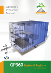
GP360 Mobile Welfare Unit
Contents
Section1
Section 2
Section 3
Section 4
Section 5
Section
Section
Section
Section
Section
Section
Section
Section
Section
6
7
8
9
10
11
12
13
14
Introduction
General Safety
Know your Groundhog
Exterior
Towing Assembly
Road Lighting
Wiring Cable
Setting up the Groundhog
Operating Instructions
Single Axle Hand Operated Hydraulics
Single Axle Electric (Lever) Hydraulics - Lever Control
Single Axle Electric (Push Button) Hydraulics - Push Button
Twin Axle Powered (Push Button) Hydraulics
Replacing a Punctured Wheel
Towing
Interior
Generator
Technical Data
Warranty
Optional Extras
Frequently asked questions
Fault Finder
2
3-4
4
4
4
4
5
6
7
8
9
10
10
11
14
15
15
16
17
17
1
GP360 Mobile Welfare Unit
GP360 Mobile Welfare Unit
Section 2. General Safety
Section 1. Introduction
Description
The GP360 Groundhog Mobile Welfare
Unit is a road towable welfare unit
suitable for up to 6 personnel.
This self contained unit has a
toilet/washroom, a drying room and a
kitchen/restroom.
Electrical supply can be taken either
from a mains hook up or from the builtin generator (available in diesel, petrol
or LPG versions).
Its unique design means that raising and
lowering the body requires little effort
from the operator and takes just 3
minutes from disconnecting to being
usable.
1
min
2
Guidance
The information and instructions included
in this manual are provided to help you
get the best possible service from your
Groundhog.
To ensure that The Groundhog is used
safely and responsibly, we strongly
recommend that this manual is read by
all users prior to its operation, and that
the recommendations are followed at all
times.
GenQuip plc operate a policy of constant
improvement and reserve the right to
change specifications without notice.
2
min
3
min
Safety
Before using this equipment and to
avoid personal injury, carefully read and
understand these instructions. If there is
anything you do not understand, DO NOT
use this equipment, contact the supplier
for advice.
Make sure you are aware of all safety
requirements and that this equipment is
suitable for the location.
When raising or lowering the unit, the
area must be cordoned off to create a
safe zone from the general public and
bystanders.
This equipment must not be moved, set
up, used or dismantled by persons who
are under the influence of alcohol or
drugs. Do not use this equipment if you
are tired or unwell.
You MUST perform a risk assessment
before siting this equipment to ensure
your safety and the safety of others.
Wear suitable personal protective
equipment whenever making
adjustments to the unit.
Do not wear loose jewellery or clothing
that may get in the way or become
trapped in the mechanism.
Carefully inspect the Groundhog before
towing or before use. If there is any
doubt about its condition, DO NOT
CONTINUE.
This equipment may only be used on
smooth level ground, which is able to
bear its weight and its load.
Risk Assessment
It is the user’s responsibility to carry out
a full risk assessment before using the
Groundhog. The risk assessment should
establish a safe zone including (but not
limited to) ground, side and overhead
hazards such as power supply and
communication cables, lighting systems,
drainage systems and other services.
Ensure that the ground on which the unit
is being used is smooth, level and
capable of withstanding the Groundhogs’
weight plus its load.
If permission is required, obtain it
before use.
Preparation for towing
Before towing the Groundhog, you must
ensure that the fresh water, waste water
and drinking water containers are
emptied.
Switch the generator OFF.
Empty the toilet and wash hand basin
reservoirs.
Pack away all utensils, cups, plates etc.
Lock all doors, window and protective
shutter.
Switch off and secure all gas bottles.
Work area preparation
Clear the ground area, where the
Groundhog is to be used, of obstructions,
anything that may puncture the tyres
and similar items. Once the unit is in the
work area, use barriers and tape to
create a safe zone. Keep bystanders and
unauthorised persons away when setting
the unit up.
3
GP360 Mobile Welfare Unit
GP360 Mobile Welfare Unit
Section 3. Know your Groundhog
1
2
8 9
7
6
4
5
Exterior
1. Steel Window Shutter
2. Nosecone
3. Towing Assembly
6
3
4
4.
5.
6.
7.
8. Toilet/Washroom
Entrance
9. Wet Room Entrance
Hydraulic Jacks
Axle
Wheel
Main Entrance
1
1
2
3
6
3
2
4
5
Road Lighting
1. Recessed Lighting Socket
2. Light Board Plug
3. Light Board
Towing Assembly
1. Jockey Wheel
2. Jockey Wheel
Securing Handle
3. Parking Brake Lever
Wiring Cable
International Standard Wiring Diagram
for 7 pin plugs and sockets
Terminal
1
6
2
7
5
3
4
Male Pin
4
4. Breakaway Cable
5. Lighting Cable and
Plug
6. Coupling Head
Female Pin
1
2
3
4
5
6
7
L
54G
3l
R
58R
54
58L
Cable
Colour
Yellow
Blue
White
Green
Brown
Red
Black
Application
LH Flasher
Rear Fog
Earth
RH Flasher
RH Tail/Wing
LH and RH Stop
LH Tail/Wc
Section 4. Setting up the
Groundhog
Positioning
The Groundhog is designed for use on
firm level ground which is able to
support the weight of the unit and its
load. During use, the trailer MUST be
uncoupled from the tow vehicle.
Drive the Groundhog to where it will be
used and manoeuvre into position. Apply
the towing vehicle’s parking brake and
switch off the engine. Next, apply the
Groundhog’s parking brake.
Uncouple the Groundhog from the towing
vehicle and move the vehicle to a safe
location.
Make a thorough inspection of the
ground below the Groundhog and
remove any foreign objects which may
cause problems.
Remove rear lighting board before
lowering the Groundhog
Nosecone
Take a firm hold of the security cover to
prevent it from swinging down and
causing injury. Remove the safety clip
and release the antiluce clip, then
carefully lower the cover.
1. Nosecone Cover Securing Bolt
2. Nosecone Cover Safety Clip
Once in position, use the key supplied to
lock the nosecone lock. If this lock is not
secured, the unit could be removed from
site without requiring entry.
1.
2.
Raising and lowering
The Groundhog is fitted with a swinging
axle which allows the shell to be
lowered to the ground. The design also
means that the wheels are “hidden”
under the body of the unit.
Once lowered, the controls and tow hitch
are secure under a lockable steel cover.
CAUTION
Keep clear of the raised unit at ALL TIMES.
NEVER enter the underside of the shell
for any reason unless it is being held by
suitable supports (correctly rated axle
stands for example).
DO NOT use the hydraulic jacks as a
means of support. Use them ONLY for
changing the unit from road towable to
static and vice versa.
Lock
Nosecone
5
GP360 Mobile Welfare Unit
Section 5. Operating Instructions
Section 5. Operating Instructions
A
B
Single Axle Manual Hydraulic Operating
Instructions
CAUTION
Keep clear of the raised shell at ALL TIMES.
NEVER enter the underneath of the shell for
any reason unless being held by suitable
supports (correctly rated axle stands for
example).
DO NOT use the hydraulic jacks as a means of
support, use them only when changing the
unit from road towable to static and vice
versa.
GP360 Mobile Welfare Unit
1
C
2
3
D
4
E
5
F
G
6
ARRIVAL AT SITE
Keep clear of the raised shell at ALL TIMES.
NEVER enter the underneath of the shell for
any reason unless being held by suitable
supports (correctly rated axle stands for
example).
Lower hydraulic rams (3) by pumping handle
Fig B)
ARRIVAL AT SITE
H
Release handbrake to “Off” position
Move lever down to lower unit to the ground
Fig G shows removed jockey wheel
Lower steel shroud over drawbar and lock in
closed position
Pump handle (2) until road wheels are clear
of ground
Replace jockey wheel into its clamp with the
pad and locking handle rotating jockey wheel
6
4
C
5
D
E
6
7
F
Fig E shows removed jockey wheel
Move lever (1) on the hydraulic pump across.
This will lower unit to the ground
Move lever (1) across
B
Remove jockey wheel (6 & 7) by turning anticlockwise, release locking handle, remove
jockey wheel, handle and pad (Fig D)
Release handbrake to “Off” position
Pull handbrake to the “ON” position
1
DO NOT use the hydraulic jacks as a means
of support, use them only when changing
the unit from road towable to static and
vice versa.
Remove jockey wheel (6 & 7) by turning anticlockwise, release locking handle, remove
jockey wheel, handle and pad (Fig F)
Open shroud and secure in upright position
with antiluce locking catch (Fig H)
3
N
DOW
DOWN
Pull lever (5) into open position (Fig C)
7
Move spring bolt (4) into open position (Fig D)
DEPARTURE FROM SITE
UP
UP
Move spring bolt (4) into open position (Fig B)
Keep pumping until road wheels are off the
ground (Fig C)
Lower steel shroud over drawbar and lock in
closed position
A
Lower rams by operating the hand lever (1)
upwards (Fig A) until road wheels are clear of
ground
Move lever (1) on hydraulic pump across (Fig A)
Pull black knob (5) into open position (Fig E)
Single Axle Electric Hydraulic Operating
Instructions - Lever Controls
CAUTION
DEPARTURE FROM SITE
handle clockwise to attach lower wheel shaft
Push black knob (5) to lock axle pins
Release spring bolt (4)
Move lever (1) across on pump , lowering the
unit onto its wheels, level and supported by
jockey wheel
Continue to pump handle (2) to fully raise
hydraulic rams
WARNING: THE FURTHER THE VALVE IS MOVEDTHE FASTER THE UNIT WILL LOWER.
Open shroud and secure in upright position
with antiluce locking catch (Fig F)
Pull handbrake to the “ON” position
Push lever (1) upwards (Fig A) until road
wheels are clear of ground
Replace jockey wheel into its clamp with the
pad and locking handle rotating jockey wheel
handle clockwise to attach lower wheel shaft
Push lever (5) to lock axle pins
Release spring bolt (4)
Move lever downwards to raise the rams until
the unit is level, on its wheels, supported by
jockey wheel
Continue to push lever downwards to fully
raise hydraulic rams
WARNING: THE FURTHER THE VALVE IS
MOVED- THE FASTER THE UNIT WILL LOWER.
7
GP360 Mobile Welfare Unit
Single Axle Electric Hydraulic Operating
Instructions - Press Button
CAUTION
1
2
Keep clear of the raised shell at ALL TIMES.
NEVER enter the underneath of the shell
for any reason unless being held by suitable
supports (correctly rated axle stands for
example).
GP500 Mobile Welfare Unit
Twin Axle Electric Hydraulic
Operating Instructions GP500 only
CAUTION
A
B
1
2
1
2
DO NOT use the hydraulic jacks as a means
of support, use them only when changing
the unit from road towable to static and
vice versa.
Keep clear of the raised shell at ALL TIMES.
NEVER enter the underneath of the shell for
any reason unless being held by suitable
supports (correctly rated axle stands
for example).
DO NOT use the hydraulic jacks as a means
of support, use them only when changing
the unit from road towable to static and
vice versa.
ARRIVAL AT SITE
ARRIVAL AT SITE
Lower rams by pressing UP button (1) on
control box (Fig A) until road wheels are clear
of ground
Lower front rams (3) by pressing the offside
‘UP’ button (1) until front wheels are clear of
ground (Fig A).
Remove jockey wheel by turning anticlockwise, release locking handle, remove
F
E
jockey wheel, handle and pad (Fig B)
Lower rear rams by pressing the nearside
‘UP’ button (1) until all wheels are clear of
ground (Fig C).
Release handbrake to “Off” position
Move spring bolt (4) into open position (Fig D)
Pull knob (5) fully out to release axle pins
(Fig D)
Press the ‘Down’ buttons (2) alternately (Fig A) Release spring bolt (4) (Fig D)
to lower unit to the ground
Pull handbrake to the “ON” position
Lower steel shroud over drawbar and lock in
Press the ‘Down’ buttons (2) alternately until
closed position (Fig E)
unit sits level on all wheels and is supported by
DEPARTURE FROM SITE
the jockey wheel
Open shroud and secure in upright position with Continue to press both ‘Down’ buttons (Fig A)
antiluce locking catch (Fig F)
until hydraulic rams are retracted fully
Raise front rams by Pressing the offside ‘UP’
NOTE:
button (1), until front wheels are clear of
1. Inside the welfare area below the work-top,
ground
is an isolator switch for the 12 volt power
Replace jockey wheel into its clamp with the
supply
pad and locking handle, rotating jockey wheel
2. In the event of a flat battery, 12 volt power
handle clockwise to attach lower wheel shaft
cables (supplied) can be connected to the
Lower rear rams by pressing the nearside ‘Up’
grey plug mounted above the drawbar and
button (1) until all wheels are clear of ground
an external 12 volt battery.
Push in knob (5) to lock axle pin (Fig D)
Move spring bolt (4) into open position (Fig B)
Pull lever (5) into open position (Fig C)
Remove jockey wheel (6 & 7), by turning
anti-clockwise, release locking handle, remove
jockey wheel, handle and pad (Fig D)
Release handbrake to “Off” position
Fig E shows removed jockey wheel
Press DOWN button (2) on control box (Fig A)
to lower unit to the ground
Lower steel shroud over drawbar and lock in
closed position
DEPARTURE FROM SITE
Open shroud and secure in upright position
with antiluce locking catch
Pull handbrake to the “ON” position
Press UP button until road wheels are clear of
ground
Press DOWN button (2) to raise the rams until
Replace jockey wheel into its clamp with the
pad and locking handle, rotating jockey wheel the unit is level, on its wheels, supported by
handle clockwise to attach lower wheel shaft jockey wheel
Continue to press DOWN button to fully raise
Push lever (5) to lock axle pins
hydraulic rams
Release spring bolt (4)
8
3
C
D
4
5
9
GP360 Mobile Welfare Unit
Section 6. Replacing a
punctured wheel
If you suffer a puncture when towing the
welfare unit, follow the next set of
instructions ONLY if the unit is on level ground
and in a position which does not place the
operators life at risk
Apply the welfare unit’s parking brake and
unhitch the unit from the towing vehicle.
Remove both lower retaining bolts from the
leaf-spring mounting plate.
Use the hydraulic system to jack the unit up
until you are able to gain access to the
wheel nuts.
Remove the wheel and replace with a
suitable spare wheel. Check that the wheel
F
Fuse Box
MCB’s
MCB's
In the kitchen/rest room
there is a consumer unit
RCD
RCD
which controls the power
Power
Power
Selected
distribution and is fitted
Selected
with suitably rated MCB’s
and an RCD.
Below the unit is a power selector switch
used to select either the power outlet sockets
or the hand wash water heater. If the ‘Hand
Wash’ is selected, no power will be available
from the power sockets.
Generator
RCD
25 amp
0024 trb
Leaf
Leaf
Spring
Spring
32amp appliance outlet
32amp appliance outlet
beneath nose cone lp67
16A MCB
10A MCB
SPARE
Position the unit on level ground and apply the
parking brake.
Turn the jockey wheel operating handle anticlockwise to raise the coupling head higher than
the vehicle’s tow ball.
Manoeuvre the towing vehicle to the unit until
the coupling head is directly over the tow ball.
Fully apply the handbrake of the towing vehicle
and switch its engine off.
Attach the breakaway cable to the ball hitch of
the towing vehicle.
Raise and hold the coupling head handle in the
raised position.
Now, turn the jockey wheel operating handle
clockwise until the coupling head is in place on
the ball. Allow the coupling to close on the ball.
Carefully check that the ball is correctly in place.
Fully raise the jockey wheel, then raise and lock
the jockey wheel assembly clear of the ground
with the wheel facing to the rear. Secure the
clamp.
Attach the lighting cable plug to the towing
vehicle’s socket and check that all the lights are
working correctly.
Once the unit is coupled to the towing vehicle,
release the welfare unit’s handbrake.
LIVE
NEUTRAL
EARTH
6A MCB
10
Lower
Lower
Retaining
Retaining
Bolt
Bolt
Section 8. Interior
SPARE
Towing Restrictions
You are advised that the Groundhog Mobile
Welfare Unit should not be towed at speeds
greater than 50 mph. The unit is not designed
for high speed towing or manooeuvering.
Towing Vehicle Suitability
The towing vehicle must be suitable for towing
the Groundhog, which has a gross weight of
1800 kg. (GP360)
Towing Brackets
The towing vehicle must have a properly fitted,
good quality towing bracket of the correct
specification for the vehicle and be fitted in
accordance with the vehicle manufacturers
recommendations.
Vehicle Registration Plate
The welfare unit must display an approved style
registration “number” plate with the same
registration mark of the towing veicle whenever
used on the road.
Towing Mirrors
You may require wing mirror extensions if your
view is obscured by the welfare unit.
Attaching the Groundhog to the Towing
Vehicle
The following instructions are conditional upon
the Mobile Welfare Unit being ready to tow.
nuts are correctly tightened.
Now lower the unit back onto its wheels,
then replace the two lower retaining bolts.
SPARE
Section 7. Towing
GP360 Mobile Welfare Unit
RCD
63
AMP
BONDED EARTH TO FRAME
OF THE UNIT
2.5MM
1.5MM
2.5MM
1
LIGHTING
SWITCHES
0
2
PANEL HEATER
3 AMP
1. STRIP LIGHT
2. BULKHEAD LIGHT
TUBULAR HEATER
1 AMP
DOUBLE 13 AMP
SOCKET
WATER HEATER
13 AMP
BATTERY CHARGER
3 AMP
SINGLE 13 AMP
SOCKET
WATER PUMP
1 AMP
Heater
To switch the heater on, simply switch ‘ON’
at the wall socket.
Heater
Heater
Wall Heater
This heater will operate
from its own MCB.
Power
Power
There is no thermostatic
Socket
Socket
heat control fitted to this
unit. Simply switch ON or
OFF as required.
Hydraulic Power Switch
R
The hydraulic power supply
is controlled by a
switch below the heater socket.
The switch
P
must be positioned
“ON” to allow the
electric hydraulics to
operate.
P
L
Bench Seats - RCD Control RCD
RCD
The seat pads of all three
Power
Power
benches can be lifted for
Socket
Socket
removal where cleaning is
required. Note, that under the
central bench is the power
socket and RCD from the
built-in petrol generator.
Drinking Water
S
Drinking water should only
be taken from the
wall mounted ‘drinking
water’ container. This
container can be filled
from a suitable mains
water supply provided
the water is fit for
human consumption.
Alternatively, refill the
container with bottled
Securing
water.
Carry
Carry
Securing Shelf
Strap
Shelf Tap
Tap Handle
Handle
Strap
Always secure to its
wall mount shelf with the securing strap
provided.
DO NOT use the container for any other
T
purpose. If you do, it must be disposed of
and a replacement obtained.
Top
Top
Soap Dispenser
Cover
Cover
The soap dispenser is suitable
Fill
Fill
for use with most liquid
soaps. To refill, raise the top
cover, pour in a suitable
amount and close the cover.
Dosing
Dosing
To obtain soap, press the
Button
Button
dosing button with the palm
of your hand.
Paper Towel Dispenser
p
The towel dispenser
is designed for use
Release
with paper towels. Release
Button
Button
R
To open, press the
Front
Front
release button on
Panel
Panel
the top of the front
panel and swing
down. Fill the unit
with the towels and
close the panel
ensuring the release button re-engages.
11
T
GP360 Mobile Welfare Unit
Section 8. Interior - Kitchen/Rest Room
Water Heater & Tap
The heater is instantaneous and has a built-in
pump for dispensing warm water. The water
used is stored in a 20 litre container beneath the
sink. Only fill the container with fresh clean
water.
Before operating the tap and heater, first check
that the power selector switch situated below
the main distribution box is set to the ‘hot wash’
position. Secondly, check that the fresh water
container is full.
To operate the heater, pass your hand close to
the panel sensor, the water will begin to flow
and be heated.
To adjust the water temperature turn the heat
dial clockwise to decrease and anti-clockwise to
increase.
When you have finished, pass your hand across
the sensor again to switch the unit OFF.
C
MIcrowave Oven
Consumer
The model of
Consumer
Unit Unit
microwave oven
will vary and you
Power
Power
Selector
Selector
are advised to
Switch
Switch
use the
Power
Power
manufacturers
Unit
Unit
instructions
Microwave
Microwave
supplied with
Oven
Oven
Drinking
the Welfare Unit.
Drinking
Water
Water
However, here is
a brief
description of
the three basic
controls.
Timer Dial
Turn the dial
clockwise to the time
Heat
required, a bell will
Setting
ring when the
Timer
cooking time is
O
Door
Door
complete.
Rotating
Release
Base
Button
Heat Setting
Turn the dial to select the level of cooking
Door release
To open the door and stop the microwave,
press the door
release
button.
Window
The window is
protected Lby
steel shutters,
which are
locked
LockBolt
Bolt
Lock
internally and
can only be
opened from
Catch
Catch
inside the rest
room.
To access the
Open
Open
shutters, first
open the
M
window.
To open the
window, release the catch and slide the left
hand glasspanel open, release lock bolt to open
the steel shutters.
When leaving the welfare unit unattended or
when transporting, the steel shutters should be
closed and locked.
Palm
Palm
Sensor
Sensor
Heat
Heat
Adjuster
Adjuster
Water
Water
Pump
Pump
Sink
Sink
Fresh
Fresh
Water
Water
Waste
Waste
Water
Water
Sink & Waste Water
Waste water from the sink is collected in a
container positioned next to the fresh water
container. Regularly check the container for
content and empty as
necessary.
Lid
Lid
Cup Dispenser F
This is a simple holder for
Cup
Cup
disposable cups which is filled
Dispenser
Dispenser
from the top and dispensed
from the bottom.
12
Section 8. Interior - Toilet
Toilet
The toilet is a self contained unit which uses
special fluids for flushing. Filling and
emptying the toilet reservoir should be
undertaken by a specialist company. Please
R
contact the supplier
for further details.
Toilet
Toilet
Pump
Pump
Handle
Handle
C
Heat
Setting
Timer
Door
Water Heater Controls - Handwash
GP360 Mobile Welfare Unit
Rotating
Base
Door
Release
Button
To operate the toilet flush after use, move
the pump lever back and forth until the toilet
bowl is clear.
Hand Wash Basin
The basin has its own reservoir of water held
within the base pillar. To fill the reservoir,
remove the filler plug fitted just below the
bowl on the right hand side.
Tap
Tap
Basin
Basin
Fill the reservoir with fresh clean water.
T
The tap is operated by depressing the pump
button repeatedly. Waste water is directed
into the toilet’s reservoir. Note that there is
not a facility for hot water.
P
Tubular Heater
Pump
PumpButton
Button
Heater
Heater
ON/OFF
ON/OFF
Wall Switch
Switch
H
13
GP360 Mobile Welfare Unit
Section 9. Generator
GP360 Mobile Welfare Unit
LPG Where Specified
To the front of the welfare unit is a locker
which is designed to hold two 19kg propane
F
gas cylinders.
F
Section 10. Technical Data
Approximate Weights and Dimensions
Gross Weight
Length
Width
Height (towing)
Height (in service)
1780 kg
3.6 m (5.1 m inc. drawbar)
2.3 m
2.7 m
2.4 m
Dipstick
Dipstick
Section 11. Warranty
of such parts.
Warranty
L
Diesel Generator
The on-board generator is used to power the
heating, lighting, hot water and power points.
There are three options - petrol, diesel or LPG
operated.
The generator is located in the wet room and
Engine
Engine
Dipstick/Engine
Dipstick/Engine
Oil
Oil Filler
The cylinder must only be connected to the
gas supply hose system when being used as a
welfare unit. Always disconnect the gas when
transporting or when not in use.
Secure all gas bottles.
If fitted with a petrol or diesel
driven engine, check fuel levels Fuel
Fuel
andP top up using clean fresh
Cap
Cap
unleaded petrol /diesel. The
fuel tank is positioned under
the floor of the wet room and its filler cap
above.
If fitted with an LPG
driven engine, check that
the LPG cylinder is
connected and its valve is
open.
To start the engine
Starter
Power
Starter ON/OFF
ON/OFF
The engine is fitted with Power
Button
Indicator
Indicator Button
Button Button
an electric start and
automatic choke/throttle.
Press the ON/OFF button then press and hold
MGTP 6000 SS LA
the start button until the
O
engine is running.
Once running, allow the
engine to warm up for at ON/OFF START
least 5 minutes before
using it to power anything.
To stop the engine, simply
press the ON/OFF button.
ON/OFF
Petrol Generator
is self contained. The controls for starting and
stopping are within the kitchen/rest room.
Before starting the generator, always check
the engine oil and fuel levels and top up as
necessary.
D
With the unit level, remove the oil dipstick
and check that the level is in line with the
maximum marker. Top up as necessary with
suitable engine oil then replace the dipstick.
14
0000136 h
ENGINE
ON
LOW OIL
PRESSURE
Your Groundhog is covered by a 12 month
warranty. GenQuip plc undertakes to replace
or repair, free of charge, any defect which the
company considers to be due to faulty
workmanship or material within 12 months
of the sale date, except for:
● Defects arising from neglect, misuse or
unauthorised modifications.
● Damage caused by abuse, misuse,
dropping or other similar damage caused by
or as a result of failure to follow
transportation, storage, loading or operating
instructions.
● Alterations, additions or repairs carried out
by persons other than the Manufacturer or
their recognised distributors.
● Transportation or shipment costs to and
from the Manufacturer or their recognised
agents, for repair or assessment against a
warranty claim, on any Mobile Welfare Unit
or component.
Important
Warranty may at the sole discretion of the
Manufacturer be void if the scheduled
service/inspections are not carried out in
accordance with the service manual.
The Manufacturer and/or their recognised
agents, directors, employees or insurers will
not be held liable for consequential or other
damages, losses or expenses in connection
with or by reason of/or the inability to use
the Mobile Welfare Unit for any purpose.
Modifications
If additional equipment or any third party
work, modifications or alterations are to be
carried out on the Mobile Welfare Unit which
will involve any welding, drilling or any form
of cutting or distortion of materials, full
written approval must be obtained from the
Manufacturer prior to the work being carried
out.
● Materials and/or labour costs to renew,
repair or replace components due to fair wear
and tear.
● Faults arising from the use of non-standard
or additional parts, or any consequential
damage or wear caused by the fitting or use
15
GP360 Mobile Welfare Unit
Section 12 .Optional Extras
Optional Extras
1. Corner Docking Points for Compressors etc
2. Lighting Mast
3. Cable Entry Points
4. Safety Pack
1. Corner Docking Point
5. Starter Pack
for Compressors etc.
Secure
Trailer Coupling
Docking Point
2. Lighting Mast
4. Safety Pack
2kg dry powder fire extinguisher.
1 - 10 person first aid kit.
Health & Safety Poster.
Notice Board.
Secure
Trailer Coupling
Docking Point
3. Cable Entry Point
5. Starter Pack
Charge units:
Drinking Water, toilet, 25mm chemical, 2
toilet rolls, paper towel, liquid soap, 25 ltres
fuel.
16