1
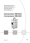
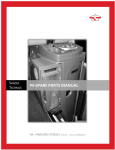
Shades Technics
Cat No. 746199
B1200-W Centre Sunken Toilet Cubicle
Parts & Service Manual
B1200-W Centre Sunken Toilet Cubicle
1
Contents
Information & Instructions
Cubicle Operating Instructions
Worktop Servery Operating Instructions
Cubicle Water Systems
Drinking Water System
Cleaning & Hygiene - Cubicle
Cleaning & Hygiene – Servery
Maintenance - Cubicle
Maintenance – Servery
Winterisation
Jump Starting
Fault Reporting Procedure
Warranty Claim Procedure Flow Chart
page 3
page 4
page 5
page 6
page 7
page 7
page 8
page 10
page 11
page 11
page 11
page 12
Parts Lists
Cubicle Exterior
Cubicle Worktop
Cubicle Internal
Cubicle Door Assembly
Cubicle Handwash Plumbing
Cubicle Flush Plumbing
Cubicle Waste Water Plumbing
Toilet Bowl Assembly
Soil Tank Assembly
WC Water Tank Assembly
Drinking Water Plumbing
Drinking Water Tank Assembly
Cap Mounted Pump Assembly
Soil Tank Evacuation Valve Assembly
Cubicle Symbol Labels
page 13
page 14
page 15
page 16
page 17
page 18
page 19
page 20
page 21
page 22
page 23
page 24
page 25
page 26
page 27
Electrical Information & Diagrams
Printed Circuit Board Layout & References
Printed Circuit Board Circuit Diagram (Sheet 1)
Printed Circuit Board Circuit Diagram (Sheet 2)
Cubicle Internal Wiring Diagram
Vehicle Wiring Diagram
page 28
page 29
page 30
page 31
page 32
Fault Analysis Flow Charts
Parts Location Reference List
Fault Chart Index
page 33
page 34
General Service Instructions
Replacing The HYDROCALOR Water Heater
Replacing The Pneumatic Valve Assembly
Replacing The Flush/Handwash/Drinks Pumps
Using Push-Fit Plumbing Fittings
Shades Technics UK Sales & Service Points
Vehicle Dealer
B1200-W Centre Sunken Toilet Cubicle
page 53
page 54
page 55
page 56
page 57
Toilet Cubicle Serial No
2
Cubicle Operating Instructions
To Switch The Cubicle On:
Engage the WC Master switch WC on the dashboard.
(It is recommended that the vehicle engine is running)
Cubicle Interior Light
Entering the cubicle automatically illuminates the light and toilet engaged light if fitted. The light will
extinguish shortly after leaving the cubicle
To Flush The Toilet:
Depress the flush button
once. A timed action opens the valve and rinses the bowl with a set
quantity of water. Should a further flush be required, wait for the flush cycle to complete then
depress the button again.
(When the HYDROFLUSH holding tank is full, the dashboard LED
will illuminate and power to
the flush pump will be cut. Emptying the holding tank will restore power.)
(When the WC water supply tank is empty the dashboard LED
will illuminate and power to
both the handwash and flush pumps will be cut. Re-filling the WC supply tank will restore power.)
To Wash Your Hands:
Depress the handwash button
once to dispense a set amount of water.
(When the WC water supply tank is empty the dashboard LED
will illuminate and power to
both the handwash and flush pumps will be cut. Re-filling the WC supply tank will restore power.)
In Case of Emergency:
Depressing the red alarm button will alert the driver.
Cubicle Extractor Fan:
The cubicle extractor fan is energised when the cubicle is on.
To Operate The Hand-Drier:
To start the cycle push the button on the front. The unit stops automatically
Water Tank Filling & Emptying
The WC supply tank is filled via the orange hose connector located behind the central near side
locker flap.
This holding tank is emptied by firmly pulling the handle on the evacuation valve connected to the
underside of the cubicle.
B1200-W Centre Sunken Toilet Cubicle
3
Worktop Servery Operating Instructions
To Switch The Servery On:
Start the vehicle engine and engage the Servery Master switch
on the dashboard.
(The engine needs to be running to operate the servery. Press the vehicle accelerator pedal twice
so the red battery symbol on the main dashboard lights is extinguished )
HYDROCALOR Water Heater
on the cubicle worktop display panel will
When the servery switch is on the Power LED
illuminate and the Hydrocalor water heater will start to warm up.
After approximately 30 minutes the Hot Drinks LED
on the cubicle worktop display panel will
illuminate to indicate the hot water has reached its optimum serving temperature.
To Dispense The Hot Water:
Depress the red button mounted on the cubicle worktop to dispense the amount of water required
(When the drinking water supply tank is empty the dashboard LED
will illuminate and power
to the drinks pump will be cut. Re-filling the Drinking water supply tank will restore power.)
Water Tank Filling
The drinking water tank is filled via the orange hose connector located behind the central near side
locker flap.
B1200-W Centre Sunken Toilet Cubicle
4
Cubicle Water Systems
HYDROFLUSH Toilet System
The push button operated flushing system is pre-set to give a powerful full covering rinse.
The water is flushed straight into a sealed holding tank which is directly coupled to the toilet bowl.
Handwash Water System
One push of the button delivers a pre-set amount of water.
All water from the cubicle sink will drain away outside the vehicle.
Water Levels
The WC supply tank provides water for both the handwash and the flushing system.
WC High Water Level
A full holding tank will illuminate the
LED on the dashboard and electrically disconnect both
pumps. Emptying the holding tank will re-energise the pumps and extinguish the dashboard LED
WC Low Water Level
An empty WC supply tank will illuminate the
LED on the dashboard and electrically
disconnect both pumps. Re-filling the WC supply tank will re-energise the pumps and extinguish
the dashboard LED.
B1200-W Centre Sunken Toilet Cubicle
5
Drinking Water Systems
HYDROCALOR Drinks System
The drinking water system is dispensed at the worktop, by depressing the button.
The Hydrocalor hot water unit is part of an un-pressurised auto-replenishment system. The
operation of pressing the button introduces cold water into the unit dispensing the equivelant
amount of hot water out of the faucet ensuring that the boiler is never empty.
The open faucet system allows the natural expansion of heated water to be relieved by
dripping from the faucet during the warm-up period. This is a normal function and the
dripping will cease when working temperature is reached.
This unit has a capacity of 5 Litres and takes approximately 25-30 minutes to reach its optimum
working temperature. Should a fault occur, causing the unit to overheat, a sensor will trip and cut
the power off.
When the unit has ‘tripped’ the
LED will be extinguished.
LED on the worktop display panel will illuminate and the
To reset, insert a thin screwdriver tip, or similar, through the label marked ‘RESET BUTTON’ on the
casing of the Hydrocalor and push the small red trip button once. (Note: The button does not have
much movement)
CAUTION
All water from the servery worktop sink will drain away outside the vehicle. Therefore care
should then be taken if the vehicle is over a service pit and hot water is washed down the
sink.
Water Levels
Drinks Low Water Level
An empty drinking water supply tank will illuminate the
LED on the dashboard and electrically
disconnect the pump. Re-filling the drinking water tank will re-energise the pump and extinguish
the dashboard LED.
B1200-W Centre Sunken Toilet Cubicle
6
Cleaning & Hygiene
Toilet Cubicle
Cubicle Cleaning
The toilet cubicle is manufactured from Glass Reinforced Plastic (GRP) with high gloss interior
surfaces and lightly textured exterior surfaces, both of which can be washed down using a mild
detergent. The use of a caustic or abrasive material is not recommended to clean internal or
external surfaces.
Toilet Bowl Cleaning
The toilet bowl is also manufactured from GRP and can be cleaned using a stiff brush with a nonabrasive, anti-bacterial detergent.
Internal Litter Bin
The cubicle features a re-usable waste sack, located inside the vanity under the sink. The sack is
attached to the vanity with velcro.
External Litter Bin
The cubicle aisle side cover features a re-usable waste sack fitted to the inside of the bin door.
The sack is attached to the door with velcro.
Soap Dispenser
To re-fill, press the lower release button and flip the front cover up. Draw out the internal soap
bottle, refill, re-fit and close the cover
Toilet Roll
It is recommended that a high biodegradable paper such as Bay West or Mini Tork is used at all
times
The toilet roll holder is incorporated into the vanity service door located below the sink. The spindle
is sprung loaded into the recess and is simply remove by pushing to one side
Do not use domestic type toilet paper (i.e Andrex) as this will clog the
Hydroflush valve and tank due to its stronger construction.
Worktop Servery
Cleaning
The drinks worktop is manufactured from Glass Reinforced Plastic (GRP) with an easy clean
surface which can be washed down using a mild detergent.
The use of a caustic or abrasive material is not recommended.
B1200-W Centre Sunken Toilet Cubicle
7
Maintenance
Cubicle Maintenance
Daily Routine
·
Prior to the vehicle entering service the holding tank should be charged with an additive to
sanitise the effluent.
·
The recommended product is Shades Super Sani ECO, a formaldehyde-free sachet with a
water soluble membrane which can be purchased in 8 gram and 16 gram sachets. A single
16 gram (or two 8 gram) sachet contains enough formula for the capacity of the holding tank
and will function for a maximum of three days.
To apply:
1.
Ensure the holding tank is empty.
2.
Check the tank evacuation valve is closed
3.
Check the WC supply tank is full.
4.
Switch on power to the cubicle (see page 3)
5.
Press the flush button to open the toilet valve and drop the complete
sachet into the holding tank.
Caution
Do not open the sachet or drop into the WC Supply Tank as this also supplies water to the
handbasin
·
It is recommended that the WC supply tank is drained and the holding tank is emptied at the
end of every day (see page 3)
·
The WC master switch WC should be turned off when the vehicle is static (parked), to
reduce the risk of battery drain if any components are left on.
Weekly Routine
·
Check extractor fan function by holding a single sheet of toilet paper in front of the chrome
grille. The air flow should draw the paper towards the grille.
·
Inspect the security of the faucet, door hinges and toilet seat lid. Check the operation of the
cubicle door and lock function. Test alarm button function.
·
Remove vanity access door, check electrical and plumbing connections for security and
leaks.
·
Check water flows through the handwash faucet is smooth and constant.
· Clean dust and fluff from AIRCALOR inlet vents using a vacuum cleaner with crevice
attachment.
B1200-W Centre Sunken Toilet Cubicle
8
Maintenance
Quartely Routine
·
Carry out weekly routine
·
Flush out holding tank with clean water. (the holding tank must be empty and the vehicle
positioned so the holding tank evacuation valve is over a sewage drainage point)
To flush out:
1. Switch on the cubicle.
2. Connect a hosepipe to a mains water supply.
3. Depress the flush button once to open the pneumatic slide
valve at the bottom of the bowl.
4. When the valve opens, insert the end of the hosepipe
down through the bowl, into the holding tank. When the
valve closes the hose will be held into position by the
paddle. The air pressure will not crush the pipe.
5. Turn on the water to the hose pipe and fill the holding tank,
being careful not to overfill. .
6. Switch off the water to the hose, press the flush button to
open the valve and remove the hose pipe.
7. Open the evacuation valve to empty the water from the
holding tank.
·
Lubricate holding tank evacuation valve. (to be carried out immediately after flushing through
the holding tank).
Undo the four fixing bolts holding the soil valve assembly together and remove the main body
section. Lubricate the slide paddle using lithium grease or similar so the open/close
operation is smooth. Replace the valve body and bolt together. Do not over tighten as this
will restrict the operation of the valve.
·
Clean out the extractor fan grille using a vacuum cleaner with a small crevice attachment.
B1200-W Centre Sunken Toilet Cubicle
9
Maintenance
Worktop Servery Maintenance
Daily Routine
·
It is recommended that the drinking water supply tank is drained daily.
·
The Servery Master switch
should be turned off when the vehicle is static (parked), to
reduce the risk of electrical damage, ‘spiking’, created by the alternator when the engine is
initially started.
Six Monthly Routine
·
Inspect security of the faucet, button and indicator LED display panel.
·
Unscrew the four fixing knobs holding the cubicle aisle cover and remove. Check electrical
and plumbing connections for security and leaks.
·
Check that the water flow through the faucet is smooth and constant.
·
Sterilise drinking water tank and system.
Unscrew the four fixing knobs holding the cubicle aisle cover and remove HYDROFILTER
from system. To remove just simply disconnect from the Push-Fit fittings either side (see
instruction at rear of manual for connection and disconnection techniques)
Sterilise tank using a proprietary product, being sure to follow the manufacturers instructions.
An access hatch is provided in the top of the drinking water tank. Please note that you will
need to purge the 5 litres of water contained in the Hydrocalor (keep hot button depressed
for 1 to 1.5 minutes)
·
Replace HYDROFILTER.
As protection against scaling and to improve the quality of the water a filter (HYDROFILTER)
is installed. This filter has a limited life and to avoid blockage it is essential to replace at 6
monthly intervals.
Prior to fitting, connect new Hydrofilter to a potable water supply and flush through in
direction of arrow until water runs clear.
B1200-W Centre Sunken Toilet Cubicle
10
Winterisation
If the vehicle is to be parked in zero or sub-zero temperatures, it is imperative that all water
containers are completely drain beforehand. This also applies to the HYDROCALOR if it has not
been in daily use
Ensure the centre grey cable to the HYDROCALOR centre signal terminal is removed when the
unit is empty and replaced only when the unit is re-filled.
Note
No warranty claims will be accepted on any winter damaged parts.
Jump Starting
When jump starting the vehicle, please ensure that both the dashboard master
Switches WC and
are off.
Fault Reporting Procedure
1.
In the unlikely event of a fault occuring an emergency parts kit has been supplied along with
the enclosed comprehensive fault analysis flow chart
Using these charts, determine the cause of the fault and replace the faulty item from the kit if
possible.
To order a replacement kit or non-kit part contact the dealer as specified on the contents
page (Page 2) of this manual, quoting the cubicle serial number.
In order for replacement goods to dispatched a simple warranty procedure must be followed.
( See flow chart on page 12)
2.
3.
4.
Notes:
·
Call-out and travelling costs are not covered by the warranty
·
Tampering, unauthorised involvement or preventable damage will result in a charge
being levied
B1200-W Centre Sunken Toilet Cubicle
11
Warranty Claim Procedure
Shades Technics offer a comprehensive warranty cover for all products, valid for 12
months from the vehicle’s date in service.
To make a claim under warranty, please follow the procedure below:
Contact the dealer or
supplier from where the
vehicle was purchased.
The dealer/supplier will then contact
Shades Technics who will fax a
warranty claim form to the customer.
Complete the warranty claim
form, ensuring all details are
filled in and fax back to
Shades Technics on
+44 (0)1992 501669
Shades Technics will dispatch any parts
required or organise rectification via one
of the service points listed at the back of
this parts & service manual
Please return any fault parts
which have been replaced
under warranty within 14
days or a charge may be
levied
B1200-W Centre Sunken Toilet Cubicle
12
Cubicle Exterior
1
2
3
4
2
5
Item Cat No
Description
1
2
3
4
5
Aisle-side Cover
Door/Panel Knob
Litter Bag
Litter Bin Door
Backdraft Vent
688700
663408
661025
688701
713820
B1200-W Centre Sunken Toilet Cubicle
13
Cubicle Worktop
2
3
5
1
4
Item Cat No
Description
1
2
3
4
5
GRP Worktop (Prepared)
LED Display Panel
Button (Red)
Drinks Faucet
15mm Sink Waste
B1200-W Centre Sunken Toilet Cubicle
688702
712511
714012
663603
701502
14
Cubicle Interior
2
3
1
12
4
5
13
6
7
8
14
9
10
11
15
B1200-W Centre Sunken Toilet Cubicle
Item Cat No
Description
1
2
3
4
5
6
7
8
9
10
11
12
13
14
15
PIR Lamp Unit
Aircalor Hand-Drier
Soap Dispenser
Handwash Faucet
Button (Blue)
Alarm Button
Chrome Grille
Toilet Roll Spindle
Vanity Door Knob
Vanity Door (Prepared)
Non-Slip Floor Strips
24v Fluorescent Tube
Button (Green)
Black Bushing
Extractor Fan
712100
661600
661646
663603
714013
714030
727200
661618
663408
688703
661480
712008
714009
713520
661510
15
Cubicle Door Assembly
Item Cat No
Description
1
2
3
4
Door Lock
Hinge (Pair)
Mounting Angle
Mirror
661206
661400
661959
661805
1
4
2
B1200-W Centre Sunken Toilet Cubicle
3
16
Handwash Plumbing Assembly
To Sink Faucet
2
1
2
From WC Tank
9
10
3
2
4
9
To Flush
Pump
2
3
3
3
6
8
5
3
5
2
6
7
3
6
3
3
2
7
3
To Waste
Plumbing
Item Cat No
Description
1
2
3
4
5
6
7
8
9
10
Equal Elbow
Stem Elbow
15mm Pipe
Service Valve
Non Return Valve
‘T’ Connector
Stop Valve
In-Line Pump
Hose Connector
½” Flexible Hose
B1200-W Centre Sunken Toilet Cubicle
747015
747016
747052
747035
747036
747020
747035
702119
747027
744030
2
17
Flush Plumbing Assembly
2
4
7
6
8
7
3
2
1
2
3
4
From Handwash
Plumbing
To Toilet Bowl
5
4
4
Item Cat No
Description
1
2
3
4
5
6
7
8
Flush pump
Male Coupler
Copper Elbow Pipe
Hose Connector
½” Flexible Hose
15mm Pipe
¾” Female Coupler
Solenoid Valve
B1200-W Centre Sunken Toilet Cubicle
702140
747028
726062
747027
744030
747052
747024
714603
5
18
Cubicle Waste Water Plumbing
3
Item Cat No
Description
1
2
3
4
5
6
7
8
9
10
11
15mm Sink Waste
Equal Elbow
15mm Pipe
½” Flexible Hose
Hose Connector
Stem Elbow
‘T’ Connector
Copper ‘S’ Pipe
22 – 15mm Reducer
¾” Flexible Hose
Sink Waste - Angled
701502
747015
747052
744030
747027
747016
747020
726062
747103
744060
701500
11
2
Worktop
Sink
1
3
2
5
Base
Flange
Handwash
Sink
10
9
4
6
3
6
6
From
Handwash
Plumbing
5
2
6
3
3
7
3
7
8
B1200-W Centre Sunken Toilet Cubicle
19
Toilet Bowl Assembly
1
7
2
3
8
4
5
Air Pipe Connections
Close
Open
6
9
Exhaust
Exhaust
Item Cat No
Description
1
2
3
4
5
6
7
8
9
Toilet Seat & Rim
Flush Nozzle
GRP Toilet Bowl
Edge Seal
Pneumatic Slide Valve
Seal Ring
Hinges (Set of 2)
Flanged Nut
Control Valve
735100
663604
688221
735738
735712
735033
735536
695504
735736
Air From Vehicle
B1200-W Centre Sunken Toilet Cubicle
20
Soil Tank Assembly
1
Item Cat No
Description
1
2
Vertical Float Switch
Large Spigot
714500
735701
2
B1200-W Centre Sunken Toilet Cubicle
21
WC Water Tank Assembly
1
2
4
5
1
2
3
2
6
1
7
8
9
Item Cat No
Description
1
2
3
4
5
6
7
8
9
Flanged Nut
15mm Connector
Non Return Valve
Lever Float Switch
22mm Connector
15mm Pipe
Stem Elbow
22mm Pipe
19mm Flexible Hose
695504
747028
747036
714510
745010
747052
747016
747053
744060
B1200-W Centre Sunken Toilet Cubicle
22
Drinking Water Plumbing
5
4
6
7
6
2
11
12
8
3
9
13
10
9
2
6
1
13
6
Item Cat No
Description
1
2
3
4
5
6
7
8
9
10
11
12
13
HYDROCALOR M5S
Hose Connector
½” Flexible Hose
Dispensing Nozzle
Stem Elbow
15mm Pipe
Service Valve
Hydrofilter Clip
Tap Adapter ¾”
Solenoid Valve
Equal Elbow
HYDROFILTER
Straight Connector
697015
747027
744040
663603
747016
747052
747035
722007
747024
714603
747015
722017
747010
B1200-W Centre Sunken Toilet Cubicle
11
6
11
11
6
To Drinks Tank
23
Drinks Tank Assembly
4
3
2
5
1
6
From Filler Connector
7
8
5
10
8
5
4
Item Cat No
Description
1
2
3
4
5
6
7
8
9
10
Cap Pump Assembly
Tank (Drilled)
22mm Connector
Stem Elbow
15mm Pipe
Hose Connector
Float Switch
Equal Elbow
Stop Valve
15mm Connector
B1200-W Centre Sunken Toilet Cubicle
702130
733650
745010
747016
747052
747027
714510
747015
747037
747028
9
5
24
Cap Mounted Pump Assembly
1
3
2
4
5
To Drinks Plumbing
6
6
7
8
8
9
9
1
Item Cat No
Description
1
2
3
4
5
6
7
8
9
10
Straight Connector
Non-Return Valve
Equal Elbow
End Stop
Sealing Gland
15mm Connector
Inspection Cap (Drilled)
Flanged Nut
15mm Pipe
Pump
747010
747036
747015
747030
726105
747028
732055
695504
747052
702118
B1200-W Centre Sunken Toilet Cubicle
10
25
Soil Tank Evacuation Valve Assembly
1
2
3
4
2
4
Item Cat No
Description
1
2
3
4
5
Small Spigot
Seal
Valve Body
Large Spigot
Replacement Handle
735700
735717
735711
735701
735715
B1200-W Centre Sunken Toilet Cubicle
26
Cubicle Symbol Labels
1
2
3
4
5
6
7
8
B1200-W Centre Sunken Toilet Cubicle
Item Cat No
Description
1
2
3
4
5
6
7
8
735560
735562
735563
735567
735561
735564
735569
735566
‘Do Not Stand’ Label
‘Flush’ Label
‘No Smoking’ Label
‘Litter Bin’ Label
‘Handwash’ Label
‘Lift To Lock’ Label
‘Toilet Paper’ Label
‘Emergency Alarm’ Label
-
735570
Full Set Of Symbol Labels
27
PCB Layout & References
Note A
Note B
NO
CAT NO
DESCRIPTION
1
2
3
4
730608
730609
715016
715018
PRINTED CIRCUIT BOARD
TIMER PRINTED CIRCUIT BOARD
70A POWER RELAY
10A/20A CHANGE OVER RELAY
FUSES
F1
5A
F2
7.5A
F3
3A
F4
7.5A
F5
3A
F6
3A
F7
5A
F8
7.5A
F9
3A
F10
7.5A
F11
7.5A
F12
10A
F13
3A
F14
3A
F15
3A
F16
30A
F17
40A
F18
40A
F19
1A
PIR Lamp
WC Water Control
Alarm Lamp & Buzzer
Coolbox 1 - Isolator & Switched Controlled
WC Master Override Switch
Servery Override Switch
Servery Services
Coolbox 2 - Isolator & Switched Controlled
HYDROCALOR (Drinks) - Signal
Coolbox 2 - Battery/Isolator Direct Control
Coolbox 1 - Battery/Isolator Direct Control
Thetford Electramagic Toilet Power
Extractor Fan
Servery Pump Buttons & Solenoid Valves
CoolboxLight & Servery Worktop Lamp
Handwash Water Heater Power
AIRCALOR Hand-Drier Power
HYDROCALOR (Drinks) Power
Timer Board
B1200-W Centre Sunken Toilet Cubicle
Note C
Notes
A Green LED’s duplicate dashboard warning lights plus when the
drinks water heater and handwash heater (where fitted) are on.
B Red LED’s indicate fuse has blown or is missing from circuit
C SW1 and SW2 can be used to override the dashboard WC and
Servery Master switches when they are off. (The PCB switches will
not work when the dashboard switches are on)
LINKS
Link 1 5A
Link 2 5A
Link 3 Link 4 Link 5 10A
Link 6 10A
Link 7 15A
Link 8 15A
RELAYS
RL 1
10/20A
RL 2
10/20A
RL 3
10/20A
RL 4
10/20A
RL 5
10/20A
RL 6
10/20A
RL 7
10/20A
RL 8
10/20A
RL 9
10/20A
RL 10 10/20A
RL 11 70A
RL 12 70A
RL 13 70A
RL 13a 70A
Handwash Pump - Pump on Demand
Handwash Pump - Autopressure
Drinks Pump - Pump on Demand
Drinks Pump - Autopressure
Toilet Flush Pump - Autopressure
Toilet Flush Pump - Pump on Demand
Coolbox 1 & 2 - Battery Direct Supply
Coolbox 1 & 2 - Isolator Direct Supply
Coolbox 2 Control
WC Water System Control
Coolbox 1 Control
Soil Tank System Control
HYDROFLUSH System Control
Hot Handwash Control
Cold Handwash Control
Servery Services
WC Services
Servery Water System Control
AIRCALOR Hand-Drier Power
HYDROCALOR (Drinks) Power
HYDROCALOR (Handwash) Power
B500 Water Heater (H/wash) Power
28
PCB Circuit Diagram 1
B1200-W Centre Sunken Toilet Cubicle
29
PCB Circuit Diagram 2
B1200-W Centre Sunken Toilet Cubicle
30
Cubicle Internal Wiring Diagram
B1200-W Centre Sunken Toilet Cubicle
31
Vehicle Wiring Diagram
B1200-W Centre Sunken Toilet Cubicle
32
Parts Location Reference List
The following list helps identifies the location of parts described during the following Fault Analysis Flow
Charts
Product Location Reference
Part on PCB
Replace Handwash
Pump (Ref A)
Check Fuse F19
Ref
Part Description
Location in Cubicle or Vehicle
See Page/Item
A
Handwash Pump
Behind cubicle vanity door panel
page 17/8
B
Flush Pump
Mounted to top of cubicle soil tank
page 18/1
C
Drinks Pump
Inside Drinking Water Tank, attached to
inspection cap
page 25/10
D
HYDROCALOR
Water Heater
Behind cubicle aisle side cover panel
page 23/1
E
HYDROFILTER
Behind cubicle aisle side cover panel
page 23/12
F
HYDROFLUSH
Pneumatic Valve
Attached to bottom of toilet bowl
page 20/5
G
Pneumatic Valve
Control Box
Behind cubicle vanity door panel
page 20/9
H
Extractor Fan
Behind cubicle vanity door panel
page 15/15
I
HYDROFLUSH
Solenoid Valve
Mounted to top of cubicle soil tank
page 18/8
J
Drinks System
Solenoid Valve
Behind cubicle aisle side cover panel
(above HYDROCALOR)
page 23/10
K
Handwash System
Non-Return Valve
Behind cubicle vanity door panel
page 17/5
L
HYDROFLUSH
Non-Return Valve
Behind cubicle vanity door panel
page 17/5
M
Drinks System
Non-Return Valve
Connected to outside top of drinks
tank inspection cap
page 25/2
N
Handwash System
Flow Regulator
Behind cubicle vanity door panel
page 17/4
B1200-W Centre Sunken Toilet Cubicle
Cat Number
33
Fault Analysis Index
Toilet Cubicle Faults
No Water From Handwash Faucet
page 35
Handwash water Runs Continuously
page 36
Water Flow From Handwash Too Slow
page 37
Water Flow From Handwash Too Fast
page 37
Delay In Handwash water Dispensing
page 38
Extractor Fan Not Functioning
page 38
Hydroflush Not Working – No Flush or Pneumatic Valve
page 39
Hydroflush Pneumatic Valve Opens – No Water Flush
page 40
Hydroflush Water Flows – Pneumatic Valve Does Not Open
page 40
Hydroflush Bowl Fills With Water When Not In Use
page 41
Water Flow Around Bowl – Not Full Coverage
page 41
Hydroflush ‘Flushing’ Constantly
page 41
PIR Light Works – No Toilet Engaged Light
page 42
PIR Light Not Working – Toilet Engaged Light On
page 42
Alarm Button Not Functioning
page 43
Aircalor Hand-Drier Not Functioning
page 44
Dashboard ‘WC Water Low’ LED Not Working
page 45
Dashboard ‘Soil Full’ LED Not Working
page 45
Dashboard ‘Alarm’ LED Not Working
page 46
Dashboard ‘WC’ Master Switch Not Working
page 46
Worktop Servery Faults
No Hot Water From Worktop Faucet
page 47
Hot Water Faucet Steaming – Water Heater Boiling
page 48
Hot Water Faucet Splutters When Dispensing Water
page 48
Delay In Drinking Water Dispensing
page 48
Cold Water From Worktop Faucet
page 49
Warm Water Only From Worktop Faucet
page 50
Water Flow From Worktop Faucet Too Slow
page 50
Worktop ‘Hot Drinks’ LED Not Working
page 51
Worktop ‘Power’ LED Not Working
page 52
B1200-W Centre Sunken Toilet Cubicle
34
No Water From Handwash Faucet
Is 'WC Water Low' LED Illuminated?
No
Yes
Is 'Toilet Full' Light Illuminated?
Replace Handwash
Pump (Ref A)
No
Check power from PCB connector
V102 Pin 9 when Pump button
Depressed
No
No water
from faucet
No
Empty soil tank
OK
Check Fuse F19
Is pump running when
button pressed?
OK
Yes
No
Open flow
regulator valve
fully
Remove Relay 7 & replace (to test only)
with Relay 5
Check Wiring Connections
between PCB & Pump
Remove cables from back of
Handwash Pump Button and
link together
Yes
Check Fuse LK1
Check power to
Handwash pump
OK
OK
Re-fill WC water tank
No water from
faucet
Water now flows
from faucet
Re-fit Relays 7 &
5 back into
original positions
Water now flows
from faucet
Re-fit cables onto
back of handwash
pump button
Remove timer
board - flip back
over and re-fit
back onto PCB
Replace Handwash
Pump Button
Remove timer board from PCB Flip over and re-plug back into
PCB using the second set of
connectors
Open
Check all pipe
connections
between tank &
pump
Relay 7 Faulty Replace
Replace PCB timer
Board
Water now flows
from faucet
No water from
faucet
Possible track
damage to PCB replace complete
PCB Board
35
B1200-W Centre Sunken Toilet Cubicle
35
Handwash Water Runs Continuously
Check Fuse LK1 is in
postion marked & not in
position marked LK2
Remove Relay 7 from
and replace (to test
only) with Relay 5
Water stops running
Water continues
to run
Relay 7 faulty
- Replace
Re-fit Relays 7 & 5
back into original
positions
Remove PCB Timer
Board and re-fit upside
down into connectors on
main PCB board
Water stops running
Replace PCB Timer
Board
Water continues to run
Remove Timer board flip back over and re-fit
back onto PCB
Check wiring
connections to pump
for short-circuit
36
B1200-W Centre Sunken Toilet Cubicle
36
Water Flow From Handwash Too Slow
Open flow regulator
(Ref N)
Water flow still slow
Water flow fast
Adjust regulator to
achieve flow required
Check all pipe
connections
Connections OK
Water flow still slow
Replace handwash
pump (Ref A)
Water Flow From Handwash Too Fast
Close flow regulator
(Ref N)
Open flow regulator
until required flow
rate is achieve
37
B1200-W Centre Sunken Toilet Cubicle
37
Delay in Handwash Water Dispensing
Check non-return
valve for blockages
(Ref K)
Replace Valve
None
Check for water leaks
in handwash plumbing
system
Extractor Fan Not Functioning
Check Fuse F13
OK
Replace Fan
(Ref H)
Check for obstruction
of the fan blades
(Ref H)
OK
OK
Check power to fan
38
B1200-W Centre Sunken Toilet Cubicle
38
Hydroflush Not Working - No Flush or Pneumatic Valve
Is 'WC Water Low' Light Illuminated?
No
Yes
Re-fill WC water tank
Is 'Toilet Full' Light Illuminated?
Check Wiring Connections
between PCB & HYDROFLUSH
System
No
Yes
Check Fuse LK6
Check power from PCB connector
V102 Pin 7 when Pump button
Depressed
OK
Empty soil tank
OK
Check Fuse F19
OK
No
Check power to
HYDROFLUSH Pump (Ref B)
Pneumatic Valve Box (Ref G)
&
Solenoid Valve (Ref I)
No
Remove Relay 5 & replace (to test only)
with Relay 7
No water from
faucet
Remove cables from back of
HYDROFLUSH Pump Button
and link together
No water
from faucet
Water now flows
from faucet
Re-fit Relays 5 &
7 back into
original positions
Water now flows
from faucet
Re-fit cables onto
back of
HYDROFLUSH
pump button
Remove timer
board - flip back
over and re-fit
back onto PCB
Replace HYDROFLUSH
Pump Button
Remove timer board from PCB Flip over and re-plug back into
PCB using the second set of
connectors
Yes
Check pump & valve
earth connections
Relay 5 Faulty Replace
Replace PCB timer
Board
Water now flows
from faucet
No water from
faucet
Possible track
damage to PCB replace complete
PCB Board
39
B1200-W Centre Sunken Toilet Cubicle
39
Hydroflush Pneumatic Valve Opens - No Water Flush
Does flush pump
(Ref B) work when
button depressed
Check power to pump
when flush button
depressed
No
Replace Flush Pump
(Ref B)
Yes
Check power to
Hydroflush solenoid
valve (Ref I) when
flush button is
depressed
Check wiring
connections
Yes
Check wiring
connections
No
Change solenoid valve
(Ref I)
Yes
No
Still no water when
flush button depressed
Check for blockages or
leaks in plumbing
Hydroflush Water Flows - Pneumatic Valve Does Not Open
Check vehicle air
pressure is at maximum
Check power to pneumatic
valve box (Ref G) when flush
button depressed
Check wiring
connections
No
Yes
Does pneumatic valve
control box release air
when flush is operated
Yes
Check for obstructions
between valve paddle
and valve body inside
toilet bowl
None
Disconnect pump wiring
and remove complete
pneumatic valve assembly
from under bowl. Do not
disconnect this assembly
from the air or electrical
supplies.
No
Yes
Does pneumatic
valve open
when flush is
operated
Check air
pipes for
restrictions
Replace Pneumatic
Control Valve
(Ref G)
Re-fit valve assembly
with minimum tension on
fixing bolts
No
Replace pneumatic
valve assembly
(Ref F)
40
B1200-W Centre Sunken Toilet Cubicle
40
Hydroflush Bowl Fills With Water When Not In Use
Check Hydroflush
solenoid valve (Ref I)
for internal obstructions
Replace solenoid
valve
(Ref I)
Water Flow Around Bowl - Not Full Coverage
Check plumbing system for water
leaks or bad connections
Hydroflush 'Flushing' Constantly
Remove Relay 5 from
PCB Board
Stops
Water Continues to Run
Replace Relay 5
Remove PCB Timer
Board and re-fit upside
down into connectors on
main PCB board
Stops
Replace Timer Board
Continues
Check wiring
connections for shortcircuit
41
B1200-W Centre Sunken Toilet Cubicle
41
PIR Light Works - No Toilet Engage Light
Check bulb in Engaged
light unit
OK
Check power at PCB
connector V101 Pin 6
No
Yes
Possible track damage to PCB Replace Complete PCB Board
Check wiring connections to
Engaged light
PIR Light Not Working - Toilet Engage Light On
Change PIR Light
Flourescent Tube
No
Replace complete
PIR Light Unit
42
B1200-W Centre Sunken Toilet Cubicle
42
Alarm Button Not Functioning
Remove terminals from
back of Alarm button
and link together
Alarm buzzer sounds
at dashboard
Change Alarm Button
Alarm buzzer does not
sound at dashboard
Does dashboard alarm
warning light illuminate
Yes
No
Check wiring
connections from button
to PCB board Connector C200
Pins 5 & 6
OK
Check vehicle wiring
from PCB board
Connector V100 Pins
1 & 5 to dashboard
mounted buzzer and
light
OK
Replace Buzzer
43
B1200-W Centre Sunken Toilet Cubicle
43
AIrcalor Hand-Drier Not Functioning
The Aircalor Hand-Drier will only function with the WC Master Switch on (with the battery light on
the dash extinguished) and the cubicle interior light on
Check Power to Aircalor
(Red + /Blue -) when
Cubicle Light is on
No
Replace Aircalor
Yes
Possible track
damage to PCB Replace complete
PCB Board
Check Fuse F17
Check Wiring
Connections between
Relay 11 PCB
connector & Relay 11
Pin 86
OK
OK
Yes
Check Power to Relay
11 PCB connector
- red wire
No
Remove Relay 11
No
Yes
Check power to
Relay 11 Pin 86 when
cubicle light is on
Check Relay 11 Pin 85
is linked to earth
Check Power to PCB
Connector V101 Pin 6
when cubicle light is on
No
Yes
No
Check Power to PCB
Connector C200 Pin 4
when cubicle light is on
Check Wiring
Connections from C200
Pin 4 to PIR Lamp
Yes
No
OK
Check wiring
connections to
AIRCALOR
Possible track
damage to PCB Replace complete
PCB Board
Replace PIR Lamp
Replace Relay 11
Check wiring between Relay 11
PCB Connector (black cable)
& Relay 11 Pin 85
44
B1200-W Centre Sunken Toilet Cubicle
44
Dashboard "WC Water Low" LED Not Working
Is PCB mounted WC LOW LED
Illuminated
Check wiring
Connections from
PCB to Dashboard
No
Yes
No
Check power to
Dashboard WC Water
Low LED
Remove Relay 2 and
replace (to test only)
with Relay 5
No LED
LED On
Possible Track
damage to PCB replace Complete
PCB Board
Relay 2 Faulty Replace
Yes
Replace WC Water
Low LED
Dashboard "Soil Tank Full" LED Not Working
Is PCB mounted SOIL FULL LED
Illuminated
Check wiring
Connections from
PCB to Dashboard
No
Yes
No
Check power to
Dashboard Soil Full
LED
Remove Relay 4 and
replace (to test only)
with Relay 5
No Light
Light On
Possible Track
damage to PCB replace Complete PCB
Board
Relay 4 Faulty Replace
Yes
Replace
Soil Full LED
45
B1200-W Centre Sunken Toilet Cubicle
45
Dashboard "Alarm" LED Not Working
Check Power to Alarm LED when
cubicle button depressed
OK
No
Replace Alarm Lamp
LED
Check Wiring
Connections to Lamp
Dashboard "WC Master" Switch Not Working
Check Power to PCB
OK
Check Fuse F3
OK
OK
Remove cables from back of
switch and link together
OK
Check Power at PCB Connector
V100 Pin 5
No
No
Possible Track
damage to PCB replace Complete
PCB Board
Check wiring
connections between
PCB & Dashboard
Replace WC Master
switch
Ntserver1/Shared/Products/B12M Cubicle/Parts & Service Manual/B12M Fault Analysis.vds
B1200-W Centre Sunken Toilet Cubicle
Issue 1
26/11/01
46
46
No Hot Water From Servery Faucet
Is 'Water Low' Light Illuminated?
No
Is pump running?
Re-fill drinking water tank
Check Power to in-line
Solenoid valve (Ref J)
Yes
No
No
Yes
Check Wiring
Connections
Relay 10 Faulty
- Replace
No
Check Power to
Drinking Pump (Ref C)
Yes
Replace Drinks
Pump (Ref C)
Check Link Tab LK3
is in position
Yes
Check Fuse F14
Remove cables from
back of worktop pump
button & link together
Water now flows
from faucet
Yes
No water from
Faucet
Replace Solenoid
Valve (Ref J)
Yes
Water now flows
from faucet
Remove Relay 10 and
replace (to test only)
with Relay 5
OK
Check power to
Worktop Pump
Button
Re-fit relays 10 &
5 back into
original positions
No water from
faucet
No
Check Wiring Connections
from PCB to Pump Button
OK
Possible track
damage to PCB Replace complete
PCB Board
Replace Worktop
Pump Button
OK
Re-fit cables onto
back of worktop
pump button
Check power to
either side of PCB
mounted Diode D3
when pump button is
depressed
Check Wiring Connections
from PCB to drinks pump
OK
No
Diode D3 Blown - Return
PCB Board for repair
Possible track damage to PCB
- Replace complete PCB Board
47
B1200-W Centre Sunken Toilet Cubicle
47
Hot Water Faucet Steaming - Water Heater Boiling
Replace Servery
HYDROCALOR
(Ref D)
Hot Water Faucet Splutters When Dispensing Water
Check plumbing fittings
are pushed home
securely
Check for small water leaks
in plumbing system
Delay in Drinking Water Dispensing
Check non-return valve
for blockages
(Ref M)
Replace non-return
valve (Ref M)
OK
Check plumbing
fittings are pushed
home securely
Check for small
water leaks in
plumbing system
48
B1200-W Centre Sunken Toilet Cubicle
48
Cold Water From Hot Water Faucet
Reset HYDROCALOR
(Ref D)
OK
Check Fuse F9
OK
Check Fuse F18
OK
Check power at grey cable on
HYDROCALOR
No
OK
Check power at small red
cable terminal on
HYDROCALOR
No
Check power to
Relay 12 Pin 86
No
Relay 12 Faulty
- Replace
OK
Remove
Relay 12 and
replace (to
test) with
Relay 11
Remove Relay 11
and re-fit back into
original base
No
Re-fit Relay 12 back into
original base
OK
OK
Replace HYDROCALOR
(Ref D)
Check power to RL12 PCB
Connector (Red Cable)
Check wiring connections
between RL12 PCB
Connector (red cable)
and Relay 12 Pin 86
OK
Possible track damage to
PCB - Replace PCB Board
No
Check wiring connections between
Relay 12 Pin 87 & Relay 12 PCB
Power Connection Stud
Check Power to
HYDROCALOR + ve Terminal
OK
No
Check wiring connections between
Relay 12 Pin 85 & Relay 12 PCB
Connector (Black cable)
Check power to Relay 12 PCB
connection stud
Replace
HYDROCALOR
(Ref D)
No
OK
Check Relay 12 Pin
85 is Linked to Earth
Check wiring
connections
OK
Possible track damage to
PCB - Replace PCB Board
No
Check wiring
connections
49
B1200-W Centre Sunken Toilet Cubicle
49
Warm Water Only from Hot Faucet
Check correct model of
HYDROCALOR fitted
(85ºC)
Yes
Replace
HYDROCALOR
(Ref D)
Water Flow From Servery Faucet Too Slow
Change
HYDROFILTER
(Ref E)
Flow still slow
None
Check for blockages
in solenoid valve
(Ref J)
None
Check for kinked or
restricted pipes
Flow still slow
Change Solenoid Valve
(Ref J)
Change Drinks Pump
(Ref C)
50
B1200-W Centre Sunken Toilet Cubicle
50
Worktop 'Hot Drinks' LED - Not Working
NOTE:
The HYDROCALOR takes approximately 25-35 minutes to reach maximum temperature(85ºC).
Please wait for 1 hour after switching on power to the unit before starting the following procedure.
Check power at yellow/green cable on
HYDROCALOR (Ref D)
No
Replace
HYDROCALOR
(Ref D)
No
Check wiring
connections
Yes
Check power to Worktop LED Panel
Yes
Replace
'Hot Drinks' LED
Worktop 'Power' LED - Not Working
This assumes that theHYDROCALOR water heater is working correctly
Is PCB Mounted "SERV HTR ON" LED
Illuminated
No
Check HYDROCALOR
Water Heater is ON
Yes
Check power to Worktop LED Panel
No
Check wiring
connections
Yes
Replace
'Power' LED
51
B1200-W Centre Sunken Toilet Cubicle
51
Dashboard "Freshwater Low" LED - Not Working
Is the PCB mounted "F/WTR LOW" LED
Illuminated
No
Yes
Remove Relay 10
and replace (to test
only) with Relay 5
Check power to
Dashboard LED
from Cubicle
No
LED
LED
On
No
Yes
Possible Track damage
to PCB - Replace
Complete PCB Board
Relay 10 Faulty
- Replace
Check wiring
connections
Replace Freshwater
Low LED
Dashboard "Servery Master" Switch - Not Working
Check power to switch from vehicle wiring
No
Yes
Check vehicle manual for
dashboard wiring
Change switch
Ntserver1/Shared/Products/B12M Cubicle/Parts & Service Manual/B12M Servery Fault Analysis.vsd
B1200-W Centre Sunken Toilet Cubicle
Issue 1 26/11/01
52
52
Service Instructions
Replacing The HYDROCALOR Water Heater
Removing the HYDROCALOR
Power
Terminals
i)
Turn off the Servery Master Switch
switch off vehicle engine
ii)
Remove the aisle side cover panel to expose the
HYDROCALOR water heater.
iii)
Pull off plumbing connectors to the inlet and outlet pipes
Caution: A small amount of water will run back out from
the outlet plumbing; this may be hot if the heater has been
used recently.
iv)
Disconnect the power cables by turning the terminal tops and
pulling the cable away.
v)
Disconnect the signal terminals by pressing down on the top of
the terminal and pulling the cable out
vi)
To remove the HYDROCALOR, undo the nut on the bracket
above the unit to release the top and unscrew the bolt in the
centre of the unit underneath to free the heater
Signal
Terminals
at the dashboard and
Replacing the HYDROCALOR
Inlet
Connector
Outlet
Connector
B1200-W Centre Sunken Toilet Cubicle
i)
Locate the HYDROCALOR in position with the terminals to the
right. Fix the unit to the bracket with the bottom bolt and the top
retaining nut.
ii)
Re-connect the power cables and ensure they are secure.
iii)
Re-connect the two outer signal cables but do not connect the
centre cable.
iv)
Re-fit the inlet and outlet plumbing connections. Check they are
secure by pulling on the pipe.
v)
Start the vehicle engine and switch on the Servery Switch
on the dashboard. Press the worktop button until the water
runs constantly (it may take up to 2 minutes to fill the heater
before the water flows)
vi)
Once the water is flowing from the worktop faucet, re-connect
the cable to the centre terminal. The HYDROCALOR will now
start to warm up.
vii)
Check for water leaks when worktop button is pressed
viii)
Re-fit the aisle side cover panel.
53
Service Instructions
Replacing The HYDROFLUSH Pneumatic Control Valve
Toilet Bowl
Close
Supply
Open
Supply
Pneumatic Valve Cylinder
Removing The Pneumatic Valve
‘O’ Ring Seal
i)
Ensure the vehicle engine is off and switch off the WC Master Switch WC on the
dashboard
ii)
Lift the toilet seat and rim and unscrew the four fixing bolts holding the bowl to the cowling
iii)
Pull the bowl assembly upwards (twisting slightly from side to side) until the bowl is free
from the soil tank and the plumbing connector to the flush nozzle is exposed.
iv)
Remove the connector to the nozzle and lift the bowl clear of the cowling.
v)
Disconnect the two air pipes to the pneumatic valve cylinder to the bottom of the bowl –
CAUTION: As this air supply is from the vehicle (via the control valve), when it is
disconnected the air pressure in the pipes will be at approx 8 bar and will cause the pipe
to ‘snake around’ violently if it is not held firmly.
vi)
Undo and remove the four fixing bolts holding the pneumatic valve to the bottom of the
bowl and remove the valve assembly
Replacing The Pneumatic Valve
i)
Position the valve assembly on the bottom of the toilet bowl and secure in place with the
bolts. Tighten bolts to 6kgf.cm using a torque wrench. (A torque conversion chart is
available on request)
ii)
Smear grease or similar around the black ‘O’ ring on the pneumatic valve and introduce
the bowl and valve assembly back into the aperture on the cowling
iii)
Reconnect the air pipes to the pneumatic valve cylinder and the plumbing pipe to the flush
nozzle.
iv)
Push the bowl assembly back into the fitting on the soil tank and push down carefully but
firmly until the bowl edge rests on the cowling top surface. Secure with the four bolts
v)
Start the vehicle engine and switch on the WC Master Switch. Wait until the vehicle air
pressure is at the maximum before attempting to flush the toilet
B1200-W Centre Sunken Toilet Cubicle
54
Service Instructions
Replacing The Flush Pump
Inlet Fitting
Outlet Fitting
1. Remove the vanity access door, open both drain taps and empty the
WC supply tank. When tank is empty, close taps.
2. Lift the toilet seat and rim and unscrew the four fixing bolts holding the
bowl to the cowling
3. Pull the bowl assembly upwards (twisting slightly from side to side)
until the bowl is free from the soil tank and the plumbing connector to
the flush nozzle is exposed.
4. Remove the connector to the nozzle and lift the bowl clear of the
cowling. The pump is located in the back right corner.
5. Pull the copper pipes from the inlet and outlet fitting to the pump (a
small amount of water will run out) and disconnect the electrical plug.
6. Unscrew the pump and remove.
7. To re-fit the pump follow procedure 6 back to 2. When re-fitting the
bowl back into the tank, oil or grease may need to be applied to the
seal on the pneumatic valve to ease insertion.
8. Re-fill WC supply tank and test flush. Allow three flushes to clear any
air in the water system
Handwash
Pump
Replacing The Handwash Pump
Handwash Pump
Drain Tap
WC Tank
Drain Tap
Elbow
Fitting
Cable
Grommet
Drinks
Pump
B1200-W Centre Sunken Toilet Cubicle
1. Remove the vanity access door, open both drain taps and empty the
WC supply tank. When tank is empty, close taps.
2. Disconnect the electrical connector to the handwash pump.
3. Pull the ‘T’ connectors from either end of the pump and remove.
4. To re-fit, push the ‘T’ connectors onto the ends of the pump and
reconnect the electrical plug.
5. Re-fill the WC supply tank.
6. Once the tank is full, open the Handwash Pump Drain Tap for 2
seconds to allow water into the pump. Test function
Replacing The Drinks Pump
1. On the top of the drinks supply tank, disconnect the elbow fitting to
the large black cap assembly.
2. Un-screw the cap assembly and remove from the tank.
3. Disconnect the pump from the electrical supply and cut off the pump
2-way connector.
4. Unscrew the top of the grey cable grommet mounted to the cap
assembly until the pump cable is loose enough to pull through.
5. Disconnect the pump from the fitting and remove.
6. To re-fit, pass the cable on the new pump up through the grommet.
Do not tighten yet.
7. Push the pump into the fitting and pull any cable slack up through the
grommet. Screw down the top of the grommet until the cable is
secure. Fit new 2-way connector (Brown = +ve Blue = -ve)
8. Screw the whole assembly into the tank until tight (do not over tighten
as this may distort the cap and cause a leak)
9. Re-connect the elbow fitting to the cap and test pump.
55
Service Instructions
Collet
Stainless Steel Teeth
PREPARTION
Cut the pipe square, ensuring
it is free of score marks, burrs
and sharp edges
Pipe
‘O’ Ring
INCOMPLETE CONNECTION
The pipe is gripped by the
fitting but not sealed. The pipe
must push 30mm into the fitting
to seal
COMPLETE CONNECTION
Push the pipe into fitting to
the internal stop. The Collet
has stainless steel teeth
which grip the pipe whilst the
‘O’ ring provides a permanent
leak-proof seal
CHECK CONNECTION
Pull on the pipe to check it is
secure. It is a good practice to
test the system this way
before use
Push in Collet
Pull Out
DISCONNECTING A FITTING
Push in collet squarely against
face of fitting. With the collet
held in position, the pipe can
be removed
DO NOT INSERT FINGERS INTO THE FITTING AS THE
STAINLESS STEEL TEETH MAY CAUSE INJURY
B1200-W Centre Sunken Toilet Cubicle
56
Shades Technics UK Sales & Service Points
1.
MIDLANDS
Flights Motor Services Ltd
Beacon House
Long Acre
Birmingham
Tel:
0121 322 2222
Fax:
0121 322 2224
Contact:
Les Sprigg
2.
LONDON
Dorset Travel Services Ltd
Victoria Coach Station (Arrivals)
3, Eccleston Place
London
Tel:
0171 730 8867
Fax:
0171 730 6492
Contact:
Glenn Pearson
3.
KENT
Simon Electronic Services
738 Maidstone Road
Wigmore
Gillingham
Kent
Tel & Fax:
01634 364889
Contact:
Simon Darby
4.
WEST COUNTRY
PCV Auto Electrical
13A Anchor Road
Kingswood
Bristol
Tel:
0831 567 801
Fax:
0117 939 0089
Contact:
Brian Cox
5
6
5.
NORTH EAST
Prolek Crook
Auto Electrical Services
Rear High Hope Street
Crook
Co Durham
Tel & Fax:
01388 762630
Contact:
Bill Simpson
7
1
9
2
4
8
3
6.
WEST YORKSHIRE
Wallace Arnold
Lowfields Road
(off Geldred Road)
Leeds
Tel:
0113 263 6456
Fax:
0113 231 0749
Contact:
Barry Mace
For EvoBus vehicles only
9.
MIDLANDS
EvoBus (UK) Ltd
Ashcroft Way
Crosspoint Business Park
Coventry
Tel:
02476 626000
Fax:
02476 262006
Contact:
Jamie Evans
B1200-W Centre Sunken Toilet Cubicle
8.
HAMPSHIRE
Pentagon of Fareham
Standard Way
Fareham
Hampshire
Tel:
01329 286224
Fax:
01329 823432
Contact:
Kevin Dart
7.
SOUTH YORKSHIRE
Moseley PCV Ltd
Elmsall Way, Dale Lane
South Elmsall
Pontefract
Tel:
01977 609 000
Fax:
01977 609 900
Contact:
Mike Coleman
57