1
INSTRUCTIONS
®
REV. 6-19-01
-J02057
Kit Numbers 91460-01, 91462-01 and 91463-01
STROBE SYSTEM FOR FLH/DYNA POLICE MODELS
General
i03259.tif
This strobe system is designed for installation on 1996 and
later FLHP, FLHTP and FXDP Model Motorcycles. HarleyDavidson police motorcycles are shipped from the factory
with the brackets necessary to mount a police pole lamp.
Kit P/N 91460-01 is a 2-point strobe system and consists of
a Strobe Power Supply, PAR-36 Strobe (blue), PAR-36
Strobe (red) and Strobe Harnesses.
Kit P/N 91462-01 and P/N 91463-01 are 3-point strobe
systems and consist of a Strobe Power Supply, PAR-36
Strobe (blue), PAR-36 Strobe (red), Strobe Harnesses and a
Strobe Pole Lamp Assembly. The Pole Lamp Assembly is
equipped with a red lens (Kit 91462-01) or blue lens (Kit
91463-01).
Knurled Ring
(Taper Up)
Lower Bracket
Knurled Ring
(Taper Down)
NOTE
See Service Parts Page Illustration for kit contents.
NOTE
A Service Manual for your motorcycle is available from your
Harley-Davidson Dealer.
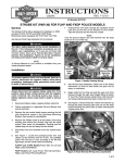
Figure 1. Pole Lamp Wiring (FLHTP Shown)
i03260.tif
1WARNING
Read this entire Instruction Sheet before beginning. If
any procedures are not within your capabilities, or you
do not have the correct tools, have your HarleyDavidson Dealer perform the installation. Inadequate
safety precautions could result in death or serious
injury.
Pole Lamp
Connector
Installation
NOTE
For Kit P/N 91460-01 (Pole Lamp not included), proceed to
Step 6.
Install Pole Lamp
(Kit P/N’s 91462-01 and 91463-01 Only)
Refer to the applicable Harley-Davidson Police Service
Manual Supplement for detailed instructions to remove
necessary components.
1.
3.
Unscrew both knurled rings from the pole lamp and
slide them off the assembly. Slide the pole lamp and
wire assembly through the upper bracket.
4.
Screw a knurled ring onto the bottom of the pole lamp
with taper up. Insert pole through bottom bracket and
thread on bottom knurled ring with taper down. Tighten
both knurled rings against bracket to lock pole in
position.
5.
See Figure 2. Locate female connector (installed at
factory) and snap male and female Deutsch connectors
together. Secure connector along saddlebag support
tube (i.e. as shown) using cable strap(s).
See Figure 1. Cut all but approximately 14 inches (254
mm) of wire off the pole lamp.
NOTE
Be sure you match the wires correctly. The black wire from
the lamp should be matched to the 2-place female
accessory connector black wire; the red wire from the lamp
should be matched to the 2-place female connector
green/red wire. If wires are not correctly matched, the
polarity for the lamp will be wrong and the lamp will not
work.
2.
Figure 2. Pole Lamp Connector (FLHTP Shown)
Follow instructions under the DEUTSCH ELECTRICAL
CONNECTORS section of the current FLT Service
Manual for terminating wires and installing socket
terminals to wires and wires to male connector.
1 of 4
Install Power Supply (All Kits)
i03977
CAUTION
Push Power Wire
Down Through Post
The power supply MUST be installed in a water tight
environment (i.e. in one of the saddlebags). Do not
mount power supply to the outside of the motorcycle or
any location which is not waterproof. If power supply
comes in contact with water, component damage could
occur.
1.
Follow instructions included with power supply and
mount in a suitable location using hardware included.
Cut
Terminal
From Wire
Tuck Ground
Wire Back
Into Bucket
Install Front Strobe Lights and Wiring (All Kits)
1WARNING
To protect against shock and accidental start-up of
vehicle, disconnect the negative battery cable before
proceeding. Inadequate safety precautions could result
in death or serious injury.
1WARNING
Always disconnect the negative battery cable first. If the
positive cable should contact ground with the negative
cable installed, the resulting sparks may cause a battery
explosion which could result in death or serious injury.
1.
Disconnect battery cables, negative battery cable first.
2.
Follow instructions in applicable Service Manual and
remove fuel tank.
3,
Remove the two socket head screws securing the left
side directional signal to the Spotlamp Mounting
Bracket. Save screws for reinstallation.
4.
Remove the Phillips screw at at the bottom of the lamp
molding and remove the chrome ring from the lamp
bucket. Save screw for reinsallation. Carefully pull the
sealed lamp unit out and away from the bucket.
5.
Disconnect the wire terminals from the sealed beam
unit.
6.
See Figure 3. Locate the spotlight power wire and
cleanly cut the terminal end off of wire. The spotlight
power wire will vary in color according to the left and
right lamps and the model. Note the following:
FLHTP/I and FLHP/I Models-Power Wire for Left and
Right Lamps-(Grey/Black)
FXDP Models-Left Lamp Power Wire-(Grey/Violet),
Right Lamp Power Wire-(Grey/Brown)
7.
Push/pull the wire down through the spotlamp mount
post and cut the wire at the entrance to the conduit.
Tape the end and tuck the wire into conduit.
NOTE
Tuck the ground (black) wire with terminal into the lamp
bucket so it is out of the way.
8.
See Service Parts Illustration. Obtain one of the Strobe
Harnesses (4) from kit and locate the open end (3
wires, no connector).
-J02057
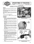
Figure 3. Modify Existing Wiring
9.
Begin with connector end at the point where the power
supply has been mounted. Route the open end of
harness along frame under fuel tank and along existing
directional lamp conduit up to front.
10. See Figure 4. Route (Push) the 3 wires from harness up
through the lamp mounting stem and out into the lamp
bucket following the same route as when removing the
original power wire.
i03978
Black
Red
Harness
Wires
White
Figure 4. Route Harness Wiring Into Lamp Bucket
11. See Service Parts Illustration. Obtain three Socket Pin
Terminals (6) and one plastic 3-place Connector (5)
from kit.
12. Follow instructions in Service Manual under “Installing
Amp Connectors” and install a socket terminal to each
of the wire ends.
13. Note the numbers marked on the plastic connector and
install each of the terminals into the following respective
cavity. Make sure the socket terminals “snap” into
place.
Red Wire Terminal to Connector Cavity 1.
Black Wire Terminal to Connector Cavity 2.
White Wire Terminal to Connector Cavity 3.
2 of 4
NOTE
When performing the following Step, the Red Par-36 Strobe
is normally installed on the left side; the Blue Par-36 Strobe
is installed on the right side.
14. See Service Parts Illustration. Obtain the left Par-36
Strobe Lamp (Red) (2) from kit and mate the harness
connector with the strobe connector.
15. Position the Strobe within the mount and reinstall the
chrome ring using the Phillips head screw removed in
Step 4. Tighten securely.
i03980
Strobe
Harness
Connectors
16. See Figure 5. Make sure conduit rests in the recess of
the clamp area as shown. Reinstall the left directional
signal assembly to the Spotlamp mounting bracket using
socket head screws removed in Step 3. Tighten screws
securely.
17. Perform Steps 3 through 16 for the right side of the
motorcycle. The Blue Par-36 strobe (1) will be used.
NOTE
Depending on which of the four outlets are chosen, the flash
pattern can be set so lamps flash alternately or
simultaneously. You may want to experiment with the various
outlets until the desired flash pattern is achieved.
i03979
Socket Head Screw
Figure 6. Connect Strobes to Power Supply Outlets
Recessed Area
21. Follow instructions in applicable Service Manual and
install fuel tank.
1WARNING
Directional
Signal
Assembly
Always connect the positive battery cable first. If the
positive cable should contact ground with the negative
cable installed, the resulting sparks may cause a battery
explosion which could result in death or serious injury.
22. Install battery cables, positive cable first.
Figure 5. Reinstall Directional Signal to Passing/Pursuit
Lamp Mounting Bracket
24. Test strobe lights for proper operation.
18. Route the left and right Strobe Harnesses under the fuel
tank then toward the back of the bike taking the same
path as the left and right directional lamp conduits.
Continue along the frame and back into the opening in
the Tour-Pak.
19. Obtain three wire ties (7) from kit and secure the strobe
harness to the frame (or directional lamp conduit) at
appropriate locations. Repeat for the other harness
20. See Figure 6. Connect the strobe harness connectors to
the power supply as shown.
-J02057
3 of 4
®
Service Parts
Part No. 29460-01 and others
Date 6/01
3-Point Strobe System
i03981
i03990.eps
4
Red or
Blue Lens
1
3
2
6
7
5
Kit P/N 91460-01
Item Description
Part No.
1
Light, strobe PAR-36 (blue lens) 68554-01
2
Light, strobe PAR-36 (red lens) 68542-01
3
Pole lamp, strobe assy (blue lens) 67623-88A
4
Harness, par-36 strobe (2)
70670-01
5
Connector, AMP socket 3-wire (2) 70289-89
6
Terminal pin socket AMP (6)
72038-71A
7
Ties, wire large (6)
10006
8
Power supply, strobe
(not shown)
91141-01
Kit P/N 91462-01
Item Description
Part No.
1
Light, strobe PAR-36 (blue lens) 68554-01
2
Light, strobe PAR-36 (red lens) 68542-01
3
Pole lamp, strobe assy (blue lens) 67623-88A
4
Harness, par-36 strobe (2)
70670-01
5
Connector, AMP socket 3-wire (2) 70289-89
6
Terminal pin socket AMP (6)
72038-71A
7
Ties, wire large (6)
10006
8
Power supply, strobe
(not shown)
91141-01
Kit P/N 91463-01
Item Description
Part No.
1
Light, strobe PAR-36 (blue lens) 68554-01
2
Light, strobe PAR-36 (red lens) 68542-01
3
Pole lamp, strobe assy (red lens) 67624-88A
4
Harness, par-36 strobe (2)
70670-01
5
Connector, AMP socket 3-wire (2) 70289-89
6
Terminal pin socket AMP (6)
72038-71A
7
Ties, wire large (6)
10006
8
Power supply, strobe
(not shown)
91141-01
-J02057
4 of 4