1
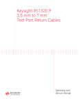
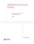
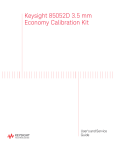
Keysight 85130G NMD 2.4 mm to 2.4 mm Adapter Kit This manual applies directly to Keysight 85130G adapters with serial number 101 and above. An adapter with an earlier (or no) serial number is not specified above 40 GHz. Operating and Service Manual Notices © Keysight Technologies 1991 – 2015 Manual Part Number No part of this manual may be reproduced in any form or by any means (including electronic storage and retrieval or translation into a foreign language) without prior agreement and written consent from Keysight Technologies as governed by United States and international copyright laws. 85130-90043 Edition January 2015 Supersedes: August 2013, October 2013 Keysight Technologies 1400 Fountaingrove Parkway Santa Rosa, CA 95403 Warranty The material contained in this document is provided “as is,” and is subject to being changed, without notice, in future editions. Further, to the maximum extent permitted by applicable law, Keysight disclaims all warranties, either express or implied, with regard to this manual and any information contained herein, including but not limited to the implied warranties of merchantability and fitness for a particular purpose. Keysight shall not be liable for errors or for incidental or consequential damages in connection with the furnishing, use, or performance of this document or of any information contained herein. Should Keysight and the user have a separate written agreement with warranty terms covering the material in this document that conflict with these terms, the warranty terms in the separate agreement shall control. Technology Licenses The hardware and/or software described in this document are furnished under a license and may be used or copied only in accordance with the terms of such license. Restricted Rights Legend If software is for use in the performance of a U.S. Government prime contract or subcontract, Software is delivered and licensed as “Commercial computer software” as defined in DFAR 252.227-7014 (June 1995), or as a “commercial item” as defined in FAR 2.101(a) or as “Restricted computer software” as defined in FAR 52.227-19 (June 1987) or any equivalent agency regulation or contract clause. Use, duplication or disclosure of Software is subject to Keysight Technologies’ standard commercial license terms, and non-DOD Departments and Agencies of the U.S. Government will receive no greater than Restricted Rights as defined in FAR 52.227-19(c)(1-2) (June 1987). U.S. Government users will receive no greater than Limited Rights as defined in FAR 52.227-14 (June 1987) or DFAR 252.227-7015 (b)(2) (November 1995), as applicable in any technical data. Safety Notices CAU TI O N A CAUTION notice denotes a hazard. It calls attention to an operating procedure, practice, or the like that, if not correctly performed or adhered to, could result in damage to the product or loss of important data. Do not proceed beyond a CAUTION notice until the indicated conditions are fully understood and met. WA RN ING A WARNING notice denotes a hazard. It calls attention to an operating procedure, practice, or the like that, if not correctly performed or adhered to, could result in personal injury or death. Do not proceed beyond a WARNING notice until the indicated conditions are fully understood and met. 85130G Adapter Kit General Information To obtain optimum performance from this adapter kit, observe these simple precautions: • Make connections carefully to avoid misalignment and connector damage, which will result in inaccurate measurements. • Keep the connectors free of dirt and any particles. • When you clean the connectors, try using compressed air first. Do not use abrasives. With a clean foam swab, apply only isopropyl alcohol. • For more information, refer to the Connector Care for RF and Microwave Coaxial Connectors document. It can be viewed online by searching for part number 08510-90064 at www.keysight.com. Description The 85130G contains two adapters, designed to protect 2.4 mm connectors (on a test set, for example). If the application requires a male test port, use the NMD-2.4 mm (f) to NMD-2.4 mm (m) adapter. If the application requires a female test port, use the NMD-2.4 mm (f) to PSC-2.4 mm (f) (precision slotless connector) adapter. Precision Slotless Connectors When properly used, a precision slotless connector should have the same lifespan as a standard slotted connector. Keysight Technologies designed the precision slotless contacts to mate with all connectors within a connector series when those connectors meet published interface dimensions. Mating a connector that does not meet published specifications can damage a precision slotless connector. For this reason, ensure that any device you connect is within its specifications. Contents The 85130G kit contains the following: • Test port adapter, NMD-2.4 mm (f) to NMD-2.4 mm (m) (Keysight part number 85130-60015) • Test port adapter, NMD-2.4 mm (f) to PSC-2.4 mm (f) (Keysight part number 85130-60016) • Storage box, foam-lined • Operating and Service Manual • Spanner wrench 85130G Operating and Service Manual 1 Device Serial Numbers The adapters in this kit are individually serialized. To help avoid confusing these adapters with similar adapters from other kits, record the serial numbers in the following table. Serialized Adapter Serial Number NMD-2.4 mm (f) to NMD-2.4 mm (m) NMD-2.4 mm (f) to PSC-2.4 mm (f) Specifications Keysight Technologies guarantees that your adapters will equal or exceed the following specifications. Figure 1 2 85130G Specifications 85130G Operating and Service Manual Connector Allowable Recession mm in NMD-2.4 mm female +0.015 to +0.056 +0.0006 to +0.0022 NMD-2.4 mm male +0.015 to +0.0254 +0.0006 to +0.0010 PSC-2.4 mm female +0.015 to +0.0254 +0.0006 to +0.0010 ELECTRICAL Adapter Frequency Range Return Loss DC to 26.5 GHz 28 dB NMD-2.4 mm (f) to NMD-2.4 mm (m) and 26.5 GHz to 40 GHz 23 dB NMD-2.4 mm (f) to PSC-2.4 mm (f) 40 GHz to 50 GHza 20 dB a. Adapters with serial number 101. Proper Use Attach the adapters to the test ports and tighten them finger tight. Use the spanner wrench to hold the test set end of the adapter and torque the test set connector with a 20 mm torque wrench set to 96 N-cm (8 in-lb). Performance Tests Use a network analyzer to perform the following return loss test on your adapters as soon as you receive them. Periodically repeat the test to determine if the performance meets the electrical specifications stated on the previous page, or if they need to be replaced. An initial period of one year between performance tests is recommended. NOTE If you are testing adapters that are not specified above 40 GHz (serial numbers below 101 and no serial numbers), replace the 50 GHz value in the previous table with the 40 GHz value. Required Equipment Keysight Model or Part Number Network analyzer – 50 GHz (or higher) measurement capability – with time domain option 010 PNA with Option 010 (See PNA Family Microwave Network Analyzers Configuration Guide, part number 5990-7745EN) 2.4 mm loads (included in the 85056A calibration kit) 00901-60003 (male) 00901-60004 (female) 2.4 mm 50 ohm airline, 5.0 cm (included in the 85057B verification kit) 85057-60001 85130G Operating and Service Manual 3 Figure 2 Return Loss Setup Return loss is measured by connecting a 50 ohm fixed load termination through a 5.0 cm airline to the adapter, then attaching the adapter to port one of the test set (see Figure 2). The effects of an imperfect load may be gated out using the network analyzer time domain option. NOTE Refer to your network analyzer’s Help system for specific instructions on using the functions mentioned in the return loss test below. 1. Preset the analyzer. 2. Set a stimulus start frequency of the analyzer’s lowest frequency. 3. Set a stimulus stop frequency of 50 GHz. 4. Set an IF bandwidth of 100 Hz. 5. Perform, and then save, a 2.4 mm 1-port S11 calibration. 6. With correction turned on, select the time domain mode. 7. Set a stimulus start time for the sweep to –0.05 nano-seconds. 8. Set a stimulus stop time for the sweep to 1.0 nano-seconds. 9. Select the gating function and gate-out everything but the adapter. See Figure 3. 10. Select the analyzer’s frequency domain mode. 11. Use the markers to read the return loss value. 4 85130G Operating and Service Manual Figure 3 Analyzer Trace Showing Location of Gates and Airline Performance Test Record ELECTRICAL SPECIFICATIONS Tested by: ______________ Date: ______________ Adapter Frequency Range NMD-2.4 mm (f) to NMD-2.4 mm (m) DC to 26.5 GHz 28 dB 26.5 GHz to 40 GHz 23 dB 40 GHz to 50 GHz 20 dB and NMD-2.4 mm (f) to PSC-2.4 mm (f) Return Loss Measured Replaceable Parts There are no replaceable components for the adapters. A worn or damaged adapter must be replaced in whole. 85130G Operating and Service Manual 5 Equipment and Supplies The following equipment and supplies are required for the maintenance and use of, but are not supplied with, your 85130G adapter. kit. Item Part Number 2.4 mm gage set (part of 85056A calibration kit) 11752-60107 (f) 11752-60108 (m) Torque wrench, 20 mm, 96 N-cm (8 in-lb) 8710-1764 Torque wrench, 5/16”, 96 N-cm (8 in-lb) (part of the 85052B calibration kits) 8710-1765 Document: Connector Care for RF and Microwave Coaxial Connectors 08510-90064 Contacting Keysight Assistance with test and measurement needs and information on finding a local Keysight office are available on the Web at: www.keysight.com/find/assist NOTE 6 In any correspondence or telephone conversation, refer to the Keysight product by its model number and full serial number. With this information, the Keysight representative can determine whether your product is still within its warranty period. 85130G Operating and Service Manual This information is subject to change without notice. © Keysight Technologies 1991 – 2015 January 2015 *85130-90043* 85130-90043 www.keysight.com