1
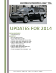
Tahoe 4wd Special Service – 5W4 | 13 Shown with aftermarket equipment Shown with aftermarket equipment Shown with optional bucket seats Updates for 2014 New Features • Concord Metallic (GWU) Deleted • • • • • • • • • Blue Ray Metallic (GXH) BLACK GRANITE METALLIC (58U) Specialty Paint Wheatland Yellow (253A) Specialty Paint Dark Toreador Red (334D) Specialty Paint Dark Blue Metallic (722J) Specialty Paint Blue (5665) Specialty Paint Green (7941) Specialty Paint Woodland Green (9015) Specialty Paint Yellow (9414) 2014 Chevrolet Municipal Vehicles Technical Manual 14 | Tahoe 4wd Special Service – 5W4 NOTE: This vehicle is NOT designed nor intended for use IN HIGH SPEED EMERGENCY VEHICLE OPERATIONS GM restricts the sale of police vehicles and they are not to be sold to retail customers. MODEL AVAILABILITY CK10706 4-wheel drive Warranty 3 years / 36,000 mile bumper-to-bumper (whichever comes first, see dealer for details) 5 years / 100,000 mile limited powertrain (whichever comes first, see dealer for details) STANDARD EQUIPMENT SUMMARY INTERIOR FEATURES Air conditioning D ual-zone manual climate control with individual climate settings for driver and front passenger; includes auxiliary rear air conditioning and heat (rear operated from front control only) Assist handlesFront passenger and second row outboard; front passenger assist handle is deleted when passenger side spotlamp is ordered Bluetooth Not available Compass Standard; displayed in Driver Information Center Console, overhead Includes map lamps Cruise control Electronic with set and resume speed DOME LampsDome lamps, cargo lamp with sustained lamps feature and map lamps (see page 24 interior/exterior lamp control to turn off dome light) Floor covering Black vinyl floor and load floor behind second row Glass Deep tinted (all windows except light-tinted glass on windshield, driver and front passenger side glass) GLove box Locking door, no light Mirror Inside rearview manual day/night Navigation System Not available OnStar Not available Outside Temp. Display Standard; displayed in Driver Information Center Radio am/fm stereo with mp3 compatible cd player, seek-and-scan, digital clock, auto-tone control, Radio Data System (rds), speedcompensated volume and theftlock Restraint systemTahoe received an overall 5-star frontal and side crash test rating from NHTSA12. Safety belts, driver and front passenger with pretensioners, dual stage driver and passenger frontal air bags1, passenger sensing system and frontal air bag1 ON/OFF indicator, rollover sensor, dual head curtain air bags1 for front and rear outboard occupants and front seat back mounted thorax-pelvic air bags1 Seat, front Cloth 40/20/40 split-bench 3-passenger, includes 6-way power driver seat adjuster (power passenger seat is not available) with manual lumbar, driver and passenger manual reclining, outboard head restraints, center fold-down storage armrest and rear storage pockets (see page 14). Bucket seats available, see A95 page 17 Seat, rear Vinyl split-folding 60/40 bench with outboard seating position headrests, 3rd seat not available (see page 14) Speedometer/cluster 120 mph analog speedometer and digital trip odometer with gages for engine oil pressure, fuel, battery volts and coolant temperature. Driver Information Center displays engine hours, warnings and other information (see message listing on page 16) Stealth MODE See exterior lamps control on page 24 for operation description Steering wheelTilt-wheel with column mounted gear shift lever Theft deterrent SystemVehicle PASS-Key® III+ and content theft (unauthorized entry sounds horn and lamps flash). For Content Theft Alarm disable option utq must be ordered (see page 19) Visors Padded with cloth trim, extends on rod; driver and front passenger illuminated vanity mirrors Warning toneS Headlamp on, key-in-ignition, driver and right-front passenger safety belt unfasten and turn signal on Window operation Power with driver express-down and lockout features Electrical features Auxiliary power, front Auxiliary power, rear Ground studs Lock-out protection Power outlets Wiring diagrams 1 00-amp ignition and main power supply wiring at lower center of instrument panel (see wiring provisions for 12-volt battery power supply on page 23) 100-amp auxiliary power in cargo area (see page 23) Two studs located in rear compartment near bottom of liftgate opening (see page 23) Prevents the power door locks from locking the driver’s door if the keys are left in the ignition (manually lockable with engine running) Two located on instrument panel and one in rear cargo area See pages 28 through 31 for description; also see Tahoe Police Package owner’s manual supplement (located in glove box folder with standard owner’s manual) Wiring PROVISION, EXTerior Lamps Flashing Forward lamp harness in-line connector for Exterior Lamps Flashing System (see option 6J7 on page 19) 1. H ead curtain side air bags are designed to help reduce the risk of head and neck injuries to front and rear seat occupants on the near side of certain side-impact collisions. Always use safety belts and the correct child restraints for your child’s age and size, even in vehicles equipped with air bags. Children are safer when properly secured in a rear seat. See your vehicle Owner’s Manual and child safety seat instructions for more information. 12. M odel tested with standard head curtain side-impact air bags (SABs). Government 5-Star Safety ratings are part of the National Highway Traffic Safety Administration’s (NHTSA’s) New Car Assessment Program (www.SaferCar.gov). 2014 Chevrolet Municipal Vehicles Technical Manual Tahoe 4wd Special Service – 5W4 | 15 Exterior Features Assist steps Body Side Moldings Defogger Door handles Door locks Black, mounted between front and rear wheels Optional (see option B85 on page 19) Electric, rear window Matte Black Power, non-programmable with lockout protection, and automatic door locking and unlocking, door lock cylinder no longer available on passenger front door and rear liftgate; child safety locks included in rear doors Fascia, front Color - keyed Fascia, rear Color - keyed with step pad Fog Lamps Not available Headlamps Dual halogen composite with flash-to-pass feature, automatic exterior lamp control and daytime running lamps (to delete automatic lamp control, see option 9G8 on page 17) Horns Dual note Keyless entryIncludes two transmitters with non-functional panic button; stealth mode feature includes exterior lamps and horn disable; if remote start Option AP3 is included, running lamps will remain illuminated (additional transmitters are available; see option AMF on page 19) Keys Two-sided random code, for ignition and driver door only Luggage rack Not available Mirrors Outside heated power-adjustable, manual-folding, Matte Black Rear liftgateLiftgate/liftglass with washer and wiper, power liftgate not available and no lock cylinder on liftgate Recovery hooks Two front Under Hood Lamp Not available Windshield wipers Intermittent with washer chassis Features Air cleaner High-capacity Alternator 160-amp with idle boost (transmission in park or neutral) based on battery energy level Battery660 CCA, 80-amp hour rating with battery rundown protection (does not protect customer installed equipment) Brakes 4-wheel anti-lock front and rear disc with vacuum boost power assist Cooling Heavy-duty high capacity radiator, electric fans and extended life coolant; coolant hoses are EPDM (ethylene-propylene-diene monomer) rubber; silicone hoses are not required (coolant is DEX-COOL good for 5 years/150,000 miles, protects from -34° F to +265° F and against rust and corrosion) Engine Vortec 5300 V8 SFI with variable valve timing (VVT), active fuel management (AFM), FlexFuel2 (capable of running on gasoline or E85 ethanol; mixtures) top speed fuel cutoff at 98 MPH Frame Full perimeter modular with hydroformed frame rails Fuel tank capacity 26 gallon (98 liters) Oil coolers Engine and transmission auxiliary air-to-oil and power steering (see page 24 for description) Radio suppression Grounding straps at five additional locations (see page 23 for location) Spark plugs Extended life - iridium tip Stabilitrak Stability enhancement system. An advanced computer controlled system that assists the driver with directional control of the vehicle in difficult driving conditions. Each time the vehicle is started, the StabiliTrak system is fully on. StabliliTrak can be controlled by a StabiliTrak button on the instrument panel located below the air conditioning fan control (see page 24). The condition of the system is displayed by an instrument panel StabiliTrak indicator light and Driver Information Center (DIC) Messages. Push once, Traction Control is off, push and hold five seconds Traction Control and StabiliTrak is off, push again and Traction Control and StabiliTrak are turned back on Steering Power, rack and pinion Suspension, front Coil-over-shock with stabilizer bar Suspension, rear Multi-link with coil springs with stabilizer bar Tires P265/70R17 all-season SBR Tire pressure monitor check tire pressure will display in driver message center (no spare tire sensor) Tire, spare Full-size spare, lockable with outside winch-type carrier mounted under frame at rear (TPM sensor not included) Trailering equipmentHeavy-duty, includes trailering hitch platform, 7-wire harness with independent fused trailering circuits mated to a 7-way sealed connector, vr4 2-inch trailering receiver and electric brake controller jumper harness Transfer case Electronic autotrac Transmission6-speed automatic with overdrive and tow/haul mode, electronically-controlled transmission provides protection against over-revving the engine in low gear and a mechanical low gear blockout is not required; if a driver manually selects low gear and fails to manually upshift to high gear, the powertrain control module automatically protects the drivetrain Wheels 17" x 7.5" argent steel Wheel center cap Argent, retained to wheel lugnuts 2. E85 is 85% ethanol and 15% gasoline. To see if there is an E85 station near you, go to www.gmaltfuel.com/e85-station-locator. 2014 Chevrolet Municipal Vehicles Technical Manual 16 | Tahoe 4wd Special Service – 5W4 POWERTRAIN ENGINETRANSMISSIONAXLE OPTION TYPE DISPLACEMENT CODE LITERS/CU. IN. LMG V8 5.3/325 EMISSIONS - FUEL OPTION TYPE SYSTEM CODE Active fuel MXO/MYC 6L80 management 6-speed FlexFuel2 auto. with OD (gas or E85 ethanol) OPTION RATIO CODE GU6 3.42 MUST BE SPECIFIED FE9 F ederal emissions. Use for ordering vehicles that will be registered in all states except California, Connecticut, Delaware, Maine, Maryland, Massachusetts, New Jersey, New York, Oregon, Pennsylvania, Rhode Island, Vermont and Washington State YF5 California emissions. Use for ordering vehicles that will be registered in California. NE1CT/ME/MD/MA/NJ/NY/OR/PA/RI/VT/WA emissions. Use for ordering vehicles that will be registered in Connecticut, Delaware, Maine, Maryland, Massachusetts, New Jersey, New York, Oregon, Pennsylvania, Rhode Island, Vermont or Washington State NB8 Required when option code FE9 “Federal emissions” is ordered for delivery to a dealer located in California, Connecticut, Delaware, Massachusetts, Maryland, New Jersey, New York, Oregon, Pennsylvania, Rhode Island and Washington State for a purchaser who will be registering the vehicle outside California, Connecticut, Maine, Maryland, Massachusetts, New Jersey, New York, Oregon, Pennsylvania, Rhode Island, Vermont and Washington State. NC7 Required when option code YF5 “CALIFORNIA EMISSIONS” or option code NE1 "CT/DE/ME/MD/MA/NJ/NM/NY/OR/PA/RI/VT/WA EMISSIONS" is ordered for delivery to a dealer located in any state except California, Connecticut, Delaware, Maine, Maryland, Massachusetts, New Jersey, New York, Oregon, Pennsylvania, Rhode Island, Vermont and Washington for a purchaser who will be registering the vehicle in one of these states or sold as permitted below under “EPA Policy on the Sale of California Emission Vehicles” NB9 Required when option code YF5 is ordered for delivery to a dealer located in Connecticut, Delaware, Maine, Maryland, Massachusetts, New Jersey, New York, Oregon, Pennsylvania, Rhode Island, Vermont and Washington. Required when option code NE1 is ordered for delivery to a dealer located in California. NOTE: T he 2014 Chevrolet Tahoe Police Patrol Vehicle and Special Service Vehicle with the 5.3L Engine (LMG) with Emission Option Codes NE1 and YF5 is certified to EPA Tier 2 Bin 4 standards and qualifies as ULEV (Ultra Low Emission Vehicle) under California Air Resources Board (CARB) requirements, meaning it is 50-state certified when ordered with NE1 or YF5. Emission Option Code FE9 (Federal) is Federal-only certified and not intended for registration in Arizona, California, Connecticut, Maine, Maryland, Massachusetts, New Jersey, New York, Oregon, Pennsylvania, Rhode Island, Vermont or Washington State. Emission Standard: BIN4 (for Option Code NE1 or YF5), BIN5 (for Option Code FE9) EPA engine family or test group: EGMXT05.3381 (for Option Code NE1 or YF5), EGMXT05.3373 (for Option Code FE9) TIRES Manufacturer Random SPEED RATED QUANTITY SIZE 5 P265/70R17 SPEED RATINGTYPE S All season BW NOTE: Optional on/off-road tire is available (see option 4JP on page 19) Tire Plys = Tread: 2 Polyester, 2 Steel, 1 Nylon Sidewall: 2 Polyster Total 7 Ply Tire chains may be used with caution. See your owner's manual for specific recommendations regarding conditions. If the vehicle is equipped with a P265/60R17 tire size use tire chains only where legal and only when necessary. Use low profile chains that add no more than 12 mm thickness to the tire tread and inner sidewall. Use chains that are the proper size for the tires. Install them on the tires of the rear axle. Don't use chains on the tires of the front axle. Tighten them as tightly as possible with the ends securely fastened. Drive slowly and follow the chain manufacturer's instructions. If the chains contact the vehicle, stop and retighten them. If the contact continues, slow down until it stops. Driving too fast or spinning the wheels with chains on will damage the vehicle. SEATS AND INTERIOR TRIM STANDARDFront: cloth 40/20/40 split-bench (power driver side seat only) Rear: vinyl 60/40 split-bench OPTIONAL Front: cloth buckets with center console (power driver and passenger seat) Rear: vinyl 60/40 split-bench OPTIONAL Front: cloth buckets without center console (power driver and passenger seat) Rear: vinyl 60/40 split-bench SEAT OPTIONSEBONY AZ3 19C 5T5 A95 19C 5T5 A95 and 9N5 19C 5T5 2. E85 is 85% ethanol and 15% gasoline. To see if there is an E85 station near you, go to www.gmaltfuel.com/e85-station-locator. 2014 Chevrolet Municipal Vehicles Technical Manual Tahoe 4wd Special Service – 5W4 | 17 AVAILABLE EXTERIOR COLORS GWT GHA 89U GAN 41U GWU 50U Champagne Silver Metallic Mocha Steel Metallic Crystal Red* Tintcoat Silver Ice Metallic Black Concord Metallic (New) Summit White Actual colors may vary * Additional Charge SEo Paint Available WA# COLOR DESCRIPTION 9260Victory Red CODE 5T4 Actual Color May VAry NOTE: • All normally body-colored non-sheet metal parts • SEO paint orders that contain less than five vehicles will be delayed until five unit minimum is received for batch production 2014 Chevrolet Municipal Vehicles Technical Manual 18 | Tahoe 4wd 5W4 – DRiver Information center United States Speedometer/cluster (CANADIAN SIMILAR) MessaGe Center change engine oil soon service air bag check tire pressure (press reset) lf/rf/lr/rr service battery charging system Driver Door Open service brake system engine hot a/c turned off service brakes soon engine oil low add oil service theft deterrent system engine overheated idle engine service tire monitor system engine overheated stop engine service traction control engine power is reduced Service stabilitrak fuel level low stabilitrak off hood open ServIce 4-Wheel drive left rear door open tighten gas cap oil pressure low stop engine tire learning active passenger door open traction control off rear access open transmission hot idle engine remote key learning active turn signal on replace battery in remote key Washer Fluid low add Fluid engine hours right rear door open NOTE: T he Tahoe Police Package and Special Service Package are not equipped with dic buttons. The instrument cluster odometer trip stem is used to display the following messages: odometer, engine hours, trip odometer, tire pressure, remote keyless entry, relearn remote key, programming and dic language. See the Tahoe owner’s manual for operation description. 2014 Chevrolet Municipal Vehicles Technical Manual Tahoe 4wd Special Service 5W4 – OptionS | 19 AVAILABLE OPTIONS WITH Tahoe 5W4 SPECIAL SERVICE PACKAGE batteries, dual - 660 CCA, 80-amp hour rating, parallel connected body side moldings - On 4 doors brake controller - Integrated trailer chassis package off-road suspension - (Requires qjp tire and includes nzz skid plates, k47 high capacity air cleaner, no z71 decal) console delete - Between seats (Requires a95) content theft alarm disable - Flashing lamps and horn warning delete daytime running lamps and automatic headlamps - Exterior lamps are operated manually (see page 24) exterior body colored parts - Victory Red special painted exterior body parts in lieu of glossy Black color normally installed with special painted bodies, Victory Red painted parts will consist of front fascia, rear bumper fascia, rear liftgate license plate applique and rear liftgate handle, door handles and body side moldings. Mirrors, rear D-pillar applique and liftgate spoiler will remain Black. Requires SEO TGK special paint and special paint color WA9260 Victory Red. Includes RPO B85 body side moldings 6j7flasher system headlamps and tail lamps - DRL compatible, headlamp flasher module with control wire and body control module rear lamp flashing (see page 27) B30 floor covering - Color keyed carpeting (includes rear cargo floor) B58 floor mats - Color keyed carpeted front and 2nd row (not available with vinyl floor covering) K05 heater - Engine block 5W4 identifier - Special Service Package 6e2 key common - Complete vehicle fleet, provides a single key with a specific code that is common to the door lock and ignition of all the vehicles in the vehicle fleet; key code is an alternate to SEO 6e8 key common, complete vehicle fleet; not compatible with 2005 and earlier Impalas, 2006 and earlier Tahoes and 2011 and later Caprice 6e8key common - Complete vehicle fleet, provides a single key with a specific code that is common to the door lock and ignition of all the vehicles in the vehicle fleet; key code is an alternate to SEO 6e2 key common, complete vehicle fleet; not compatible with 2005 and earlier Impalas and 2006 and earlier Tahoes and 2011 and later Caprice AMF Keyless entry transmitters - Fleet Package includes 6 additional transmitters. Transmitters are not programmed. Each transmitter, including the two standard with the vehicle, must be programmed together by a dealer at customer expense. Transmitter programming is not a warranty item. See also your owner's manual supplement for programming information. (see also page 25 for customer programming of transmitters using the vehicles Driver Information Center procedure) NOTE: Vehicle specific, common fleet transmitter frequency not available G80 locking differential Trw provision for roof mounted lamp - Overhead console mounted switch and wiring to the roof; upfitter to install and connect a roof mounted warning lamp; instructions provided in owner’s manual supplement (see page 25) 6b2 rear door handles inoperative - Rear door inoperative; doors can be opened only from outside (see page 25) 6n6 Rear door locks inoperative - Rear power locks are inoperable at rear doors but operate form drivers position (see page 25) 6n5 rear door window switches inoperative - Rear window only operates from driver’s position (see page 25) Ap3 remote vehicle starter system - Includes remote keyless entry Az3 seats - Front custom cloth 40/20/40 split-bench, power driver seat only (see page 16) A95 seats - Front bucket with custom cloth, 6-way power with center console, to delete center floor console 9n5 must be ordered (see page 16) 5t5 seats - Front cloth with vinyl rear seat (see page 16) Nzz skid plates package TGKSPECIAL PAINT SOLID - One color all normally body-colored non-sheet metal parts will be gloss Black. This includes front and rear facias, liftgate handle and applique, D-pillars and upper liftgate applique. Mirrors and door handles will be grained Black parts. B85 body-side moldings are not available except with SEO option 5T4 exterior body-colored parts. May require extended lead time. Required with any SEO paint selection. May require extended lead time 7x6 spotlamp - Left hand, separately fused (see page 26) 7x7 spotlamp - Left and right hand, separately fused (see page 26) 4JP tire SPare - P265/70R17 on/off-road, blackwall (requires QJP tires) Qjp tires - P265/70R17 on/off-road (for full-size spare tire 4JP must be ordered) P46 wheels - Aluminum Wx7wiring - For customer connection to front door and windshield pillar speakers. Front speakers are not connected to the vehicle radio; radio audio signals are routed to the rear speakers (see page 26) 6j3 wiring - For grille lamps and siren speaker (see page 27) 6j4 wiring - For horn/siren circuit, in-line connection for customer furnished switch (see page 26) Autonet Mobile WiFi in-car router - Available through your GM Dealer (see page 26) K5T B85 Jl1 9g3 9n5 Utq 9g8 5t4 For standard and optional illustrations see pages 23 though 27 2014 Chevrolet Municipal Vehicles Technical Manual 20 | Tahoe GENERAL 4wd Special Service 5W4 – Specifications ENGINE Model Drive CK10706 4-wheel EXTERIOR (in./mm) Wheelbase Overall length Overall width Overall height* Lift in height (load floor to ground) Step height - (front door sill to ground) Step height - (rear door sill to ground) Step height - (front running board to ground) Step height - (rear running board to ground) Front track width Rear track width Turning diameter curb to curb (ft./m) Ground clearance* - (front axel) Ground clearance* - (rear axel) 116.0/2946 202.0/5131 79.0/2007 76.9/1953 32.6/828 22.3/567 22.8/580 14.0/356 14.5/369 68.2/1732 67.0/1701 39.0/11.9 10.5/266.7 9.1/231 FRONT COMPARTMENT (in./mm) Head room Shoulder room Hip room Leg room 41.1/1044 65.2/1656 60.3/1532 41.3/1049 REAR COMPARTMENT (in./mm) Head room Shoulder room Hip room Leg room 39.2/996 65.2/1656 60.6/1539 39.0/991 CARGO Load floor length to center front seat at floor (in./mm) Load floor length to center 2nd seat at floor (in./mm) Inside width between wheel house (in./mm) Cargo area height (in./mm) Cargo volume3 maximum behind front seat (cu. ft./liters) Cargo volume3 maximum behind second seat (cu. ft./liters) 81.4/2068 49.4/1255 49.1/1247 41.7/1059 108.9/3084 60.3/1707 Type Displacement: liters/cu. in. Horsepower/rpm Torque lb.-ft./rpm Induction system Compression ratio Exhaust Minimum recommended fuel octane Fuel tank capacity (gallons/liters) Oil with filter (quarts/liters) Cooling capacity (quarts/liters) TRANSMISSION Automatic electronic with overdrive Fluid pan removed and filter replaced (quarts/liters) Ratio 4-wheel drive ABS with vacuum boost Front - swept area (sq. in./sq. cm) Rear - swept area (sq. in./sq. cm) Total front and rear swept area (sq. in./sq. cm) Front rotor diameter (in./mm) Rear rotor diameter (in./mm) Front rotor thickness (in./mm) Rear rotor thickness (in./mm) Type Size CITY/HIGHWAY/COMBINED 15/21/17 Projected EPA label values, actual mileage will vary with options, driving conditions, driving habits and vehicles condition. ALTERNATOR Type Amps 77°F (25°C) REMY DR44M 160 Tahoe POLICE ALTERNATOR OUTPUT S-Rated All Season P265/70R17 WHEELS CHASSIS 5.3L engine 4WD4 Disc/Disc 256.6/1655 248/1600 504.6/3255 13.0/330 13.5/343 1.2/30 .79/20 TIRES Passenger compartment volume index3 Fuel Economy Ratings 3.42 BRAKES Type Size 121.8/ 3449 6-speed 6.0/5.7 AXLE PASSENGER COMPARTMENT VOLUME INDEX (cu.ft./liters) NOTE: For additional dimensional data go to: gmupfitter.com Vortec V8 5.3/325 320 @ 5400 335 @ 4000 sfi 9.9:1 Single 87 26/98 6.0/5.7 18.3/17.3 Frame Front suspension Rear suspension Steering type Steering ratio Steel S-Rated All Season 17" x 7.5" Full perimeter steel Independent, single coil-over-shock with stabilizer bar Multi-link with coil spring Power rack and pinion 17.75:1 BATTERY Type BCI group size Volts Amp hour rating Cold cranking-amps @ 0°F (-18°C ) Reserve capacity @ 80°F (27°C) Maintenance free LN3 12 80 660 135 minutes Vehicle Weight (lbs./kg.) NORMAL IDLE SPEED: 600-650 RPMS COMPUTER CONTROLLED IDLE SPEED RANGE (PARK): 800-1000 RPM 3. Cargo and load capacity limited by weight and distribution. 4. EPA-estimated MPG. 5. Gross Vehicle Weight Rating (GVWR). When properly equipped, includes vehicle, passengers, cargo and equipment. 6. Maximum payload capacity includes weight of driver, passengers, optional equipment and cargo. GVWR5 4-wheel drive Curb weight10 Payload6 with 40/20/40 split-bench seat GCWR (gross combination weight ratings) Maximum trailer weight7 NOTE: See owner’s manual supplement for loading information 7300/3311 5627/2552 1673/759 14000/6350 8200/3720 7. Maximum trailer weight ratings are calculated assuming a base vehicle, except for any option(s) necessary to achieve the rating, plus driver. The weight of other optional equipment, passengers and cargo will reduce the maximum trailer weight your vehicle can tow. 10. Curb weight in operational status with 100% fuel, fluids and standard base equipment (excludes optional content) * Published dimensions indicated are at curb weight 2014 Chevrolet Municipal Vehicles Technical Manual Tahoe Special Service 5W4 – Vehicle load limits | 21 This information is intended for those who intend to install additional equipment to the police vehicle after it has left the factory, and for those who will be driving and loading the vehicle with passengers and/or cargo. Two labels on your vehicle show how much weight it was designed to carry, the Tire and Loading Information label and the Certification/Tire label. These labels are attached to your vehicle and give you the maximum load capacity, the Gross Vehicle Weight Rating (GVWR) and the Gross Axle Weight Rating (GAWR) for your vehicle. See "Vehicle Load Limits" in the owner manual Index for additional loading information. The following guidelines can help you with proper loading and load distribution when installing additional equipment on the TahoePolice Package. WARNING Do not load the vehicle any heavier than the Gross Vehicle Weight Rating (GVWR), or either the maximum front or rear Gross Axle Weight Rating (GAWR). This can cause systems to break and change the way the vehicle handles. This could cause loss of control and a crash. Overloading can also shorten the life of the vehicle. Adding Equipment to Your Vehicle Before adding accessories or equipment to your police vehicle, there are some things you need to know • The police vehicle's maximum capacity weight (payload). The weight of your police vehicle, including a full tank of fuel but without a driver and passengers. • The weight of items you plan on adding to your police vehicle, like roof mounted light bar(s), push bumpers, security barrier(s), rear storage organizer, highway flares, fire extinguishers, weapons, ammunition, radios, and video equipment. • The weight and number of passengers you intend to carry in your vehicle. • The total weight of any additional cargo you intend to carry in your vehicle. When planning your vehicle equipment installation remember not to exceed the Gross Vehicle Weight Rating (GVWR) or the Gross Axle Weight Rating (GAWR) of the front or rear axles. To keep the available load weight less than the vehicle capacity weight, you may need to limit the number of passengers you carry in your vehicle or change your choice of additional equipment. Center of Gravity (CG) A vehicle's center of gravity is an imaginary location inside the vehicle and is a balance point for the vehicle mass as it moves down the road. The police vehicle's center of gravity, before you add a load and passengers, is approximately midway between the center of the axles, up from the ground to just below the front window, and between the driver and passenger. Equipment location and weight on the vehicle's center of gravity is important to keep in mind when planning an installation. Heavy equipment should be positioned as low and as far forward in the rear load compartment as possible. Try to mount the equipment below the bottom of the side windows. Refer to the Loading Zone chart and diagram to help with your installation plan. A procedure to make the necessary measurements and formulas to calculate the vehicle longitudinal, lateral and vertical position of the center of gravity can be found in the GM Coachbuilders Manual. Equipment required to conduct the measurements for calculating the center of gravity are: • Weight scales of sufficient capacity to measure the vehicle weight at each wheel. • A post type hoist or other means to safely elevate the front of the vehicle to at least an angle of 20 degrees above horizontal. See your GM dealer to get more information about this coachbuilder procedure. Keeping the center of gravity midway between the axles is also important to provide proper braking performance. About half the total vehicle weight on each axle is recommended. Weigh your vehicle after the additional equipment has been installed to determine the actual weight of your vehicle. Weigh the vehicle with a full tank of fuel and without passengers. You may need to put a limit on how many people or other equipment you can carry inside your vehicle after the additional equipment has been installed. Note: See loading zone weight chart and diagram on page 22 2014 Chevrolet Municipal Vehicles Technical Manual 22 | Tahoe 4wd Special Service 5W4 – Loading Zones Loading zone for customer installed equipment and cargo without passengers Loading Zone Weight Chart – Tahoe Special Service Package (5W4) 38 lbs (17 kg) 52 lbs (24 kg) 90 lbs (41 kg) 137 lbs (62 kg) 546 lbs (248 kg) 683 lbs (310 kg) 175 lbs (80 kg) 598 lbs (271 kg) 773 lbs (351 kg) 2014 Chevrolet Municipal Vehicles Technical Manual Tahoe PPV & 5W4 special equipment - STANDARD | 23 AUxiliary Battery Power Junction Block and Ground Studs An auxiliary power junction block is located within the driver’s side rear cargo area jack stowage compartment. This junction block is split to provide two circuits for connection to customer-furnished equipment directly to the battery through separate 50-amp circuit breakers. These circuit breakers are located in the breaker/relay panel forward of the instrument panel glove box. A maximum load of 100-amps (1,200-watts) can be connected. This junction block is connected to a coiled 5-foot (1.5 m) branch of rear body harness and fastened near the jack. Mounting of the junction block can be at customer-selected rear cargo area locations permitted by the branch harness length and using customer-furnished mounting hardware. The junction block should not be attached to the interior trim plastic components without appropriate backing hardware to the mounting bolts. Grounding studs are located on the left and right sides of the liftgate opening. Radio Suppression Ground Straps 4 1 3 5 2 Police Package is equipped with additional grounding in the following locations: 1. Left hand front frame body mount bracket to underbody 2. Left hand rear frame body mount bracket to rear underbody 3.Right hand rear frame body mount bracket to rear underbody 4.Right hand center frame body mount bracket to center underbody 5. Exhaust pipe hanger rod to rear frame hanger Tire Pressure Monitor Your vehicle is equipped with a Tire Pressure Monitor (tpm) System which warns of low tire pressure. The tpm System on your Tahoe Police Package has a spare tire sensor but is not programmed to read the spare tire pressure. When the spare tire from your vehicle or an unused spare tire from another Police Package is placed in use as a road wheel, the system will not read the presence of the new tpm sensor and must be calibrated. Refer to your owner’s manual for additional information on the Tire Pressure Monitor and Sensor Programming. The Special Service Package 5W4 does not have sensor in spare tire. Wiring Provisions for 12-volt battery power supply Your vehicle is equipped with wiring provisions for a 12-volt battery power supply. Refer to the following information when adding electrical system. The wiring harness is located below the instrument panel near the center of the vehicle. The following information describes the breaker and relay location. The 12-volt battery power is supplied through two underhood mega fuses, one 125-amp and one 60-amp. This underhood power is fed to the breaker/relay center via a harness that passes through the driver side front of the dash, and routed across the instrument pane to a position forward of the glove box. The breaker/ relay center is mounted to the instrument panel structure forward of the glove box. The center includes a plastic bracket, two relays, two 30-amp breakers and three 50-amp mega circuit breakers. Two 30-amp breakers supply power from the underhood 60-amp mega fuse through the contacts of the control relays to a 12-gauge (3.0 mm2) blunt cut wires. These two blunt cut leads are part of wire coiled under the instrument panel near the center of the vehicle. Each relay is operated by a 0.5 mm2 blunt cut, light or dark blue control lead includes in a 3-foot (91 cm) loop of wire under the instrument panel. Three 50-amp mega circuit breakers, protected by three fusible links, supply power directly from the underhood 125-amp mega fuse through three, 10-gauge (5.0 mm2) wires. Two of the wires are routed through the body harness to a split buss junction block to the left rear of the cargo area and secured near the jack and tools. This 3-foot (91 cm) of coiled wires can be accessed by removing the cup holder on the top of the trim panel. The third 10-gauge (5.0 mm2) wire is a blunt cut lead, which is part of the 3-foot (91 cm) loop of wire coiled under the instrument panel near the center of the vehicle. An 8-gauge (8 mm2) ground lead is also provided and it is located under the front passenger sill plate. It can be accessed by removing the sill plate and pulling the loop of wire at the front of the plate, the lead is 3-feet (91 cm) long. Blunt cut ignition control power and signal circuits are also included in the wire coiled under the instrument panel near the center of the vehicle. They include: • A yellow, 20-gauge (0.5 mm2) circuit, hot in ACCESSORY, RUN or RAP (Retained Accessory Power)* • Pink, 20-gauge (0.5 mm2) circuit, hot in Start/Run (7-amp maximum load) • A yellow/black, 20-gauge (0.5 mm2) transmission park signal. This circuit provides switched power when the transmission is in P (Park) and the engine is running. The circuit is at 0-volts when the transmission is in any other position, i.e., R (Reverse), N (Neutral), D (Drive) or M (Manual 6-1). NOTE that the circuit is also at 12-volts with the transmission in P (Park) and the ignition is OFF. To avoid the possibility of undesired parasitic electrical load with the ignition is OFF it is suggested that the Park/Signal circuit be isolated by routing it through the normally open contacts of a customer furnished ignition controlled relay.* • A dark green/white, 20-gauge (0.5 mm2) Vehicle Speed Signal (VSS) provides 4,000 pulses per mile. The breaker and relay center is located behind and above the instrument panel storage compartment. Remove contents from the storage tray. Using the tab at the back of the compartment drop the tray down gently toward the floor. You will find the breaker/relay center above the right rear corner of the storage compartment. * These two circuits share a 15-amp fuse. (10-amp combined maximum load) NOTE: For wiring diagram see pages 28 through 31 2014 Chevrolet Municipal Vehicles Technical Manual 24 | Tahoe PPV & 5W4 special equipment - STANDARD Interior/Exterior LampS Control (PPV ONLY) Engine Oil Cooler (5W4 ONLY) 9G8 - Delete Daytime Running Lamps and Automatic Headlamps. This option disables the Daytime Running Lamps and Automatic Headlamps control feature. Exterior lamps are manually controlled only. Option 9G8 not available in Canada. Courtesy lamps, including dome lamps, can be turned off with a push button switch which is above the interior lamp intensity control knob. When the switch is activated, courtesy lamps remain off when any vehicle door is open. If a door is open when the switch is activated, the lamps will go off. The instrument cluster and radio lighting dimmer control will override the push button switch to turn on the courtesy lamps. The headlamp control on the driver’s side of the instrument panel operates the headlamps. If your Tahoe does not have option 9G8, Delete Daytime Running Lamps and Automatic Headlamps, the Daytime Running Lamps and Automatic Headlamps can be turned off for one ignition cycle by rotating the control knob momentarily counter-clockwise. See also section 3 of your Tahoe owner’s manual. In Canada, the Daytime Running Lamps and Automatic Headlamps can be turned off if the transmission is in Park. See also your Tahoe owner’s manual. Engine oil cooler located in the left hand radiator tank. Cooler consists of an inlet and an outlet pipe attached to the engine oil filter adapter which transmits the oil to the cooler and then back to the engine. The cooler itself consists of numerous flat plates through which the hot oil flows, transmitting heat to the coolant and cooling the oil. Transmission Oil cooler Service parts identification label E L MP SERVICE PARTS IDENTIFICATION DO NOT REMOVE 1GNLC2E0BR8152140 AGK BDR IPG OST UW6 3FL 7X6 BC/CC AG2 B3B JA9 QPP UIC 6A3 8MZ AL0 AMF B42 B86 JL9 KD1 R7V R9N U77 VT7 6E2 6HP PPV 9MZ U 636R SA AP3 B9V KG4 R9Z V8D 6J1 AR9 C67 LGD SLM WL9 6J3 AT8 DK2 MX0 T53 ZFH 6J4 PDBJCH AXJ AY0 EF7 E2C M15 NK5 UH8 UJM 1SZ 19C 6J7 7B3 A75 FE9 NT7 UN9 41U 7HP CC10706 A76 FR9 N99 UT7 191 7M9 External air-to-oil cooler is mounted in front of coolant radiator and A/C condenser at the center and is connected in series with the integral transmission oil cooler in the right end tank of the coolant radiator. Power steering cooler A Service Parts Identification (SPID) Label provides Vehicle Identification Number (VIN)-specific Option Code content list, Engineering Model Number (Nameplate, body style), Exterior paint system, Exterior paint color code and Interior trim level and color. The SPID label for the Tahoe is located on the inner surface of the instrument panel storage compartment (glove box). Stabilitrak control Vertical finned cooler is mounted in front of the radiator at the left side of the radiator and connected in-line between the power steering pump and steering gear. Covering - Floor OFF The Stabilitrak stability control system control button is located below the air conditioning fan control See pages 3 or 15 of this manual for an operation description of the stability control system or see your Owner's Manual. Black heavy-duty one piece. Replaces production carpeting. 2014 Chevrolet Municipal Vehicles Technical Manual Tahoe PPV & 5W4 special equipment - OPTIONAL | 25 AMF - Package of 6 transmitters With Remote Start and Liftglass (Without Remote Similar) 6B2 – Rear Door Handles Inoperative With Remote Start and Power Liftgate and Liftglass (Without Remote Start Similar) Relearn Remote Key To access this DIC display, the vehicle must be in PARK. This display allows you to match the remote keyless entry transmitter to your vehicle. To match a remote keyless entry transmitter to your vehicle, do the following: 1. Press the trip odometer reset stem until PRESS THE RELEARN REMOTE KEY displays. 2. Press and hold the trip reset stem for 3 seeconds. The message REMOTE KEY LEARNING ACTIVE will display. 3. Press and hold the LOCK and UNLOCK buttons on the first transmitter at the same time for approximately 15 seconds. A beep will sound indicating that the transmitter is matched. 4. To match additional transmitters at this time, repeat Step 3. Each vehicle can have a maximum of eight transmitters matched to it. 5. To exit the program mode, turn the key to the LOCK position. NOTE: A maximum of 8 keys may be learned for a vehicle immobilizer (Passkey III+) with a random key code. Vehicles with the fleet key option (RPO 6E2 or 6E8) may have an unlimited number of keys learned for the particular option fleet key and must be learned using one of the original "master" keys. When programming the RPO AMF additional 6 remote transmitters, the original 2 transmitters delivered with a vehicle must also be reprogrammed at the same time. A maximum of 8 remote transmitters can be programmed for a single vehicle. Inside rear door handles are disconnected. Rear doors can only be opened from the outside. 6N5 SWITCHES – REar Window Inoperative Rear door window switches are inoperable. Rear door power regulators are operable only from driver position switches. 6N6 – Rear Door Locks Inoperative TRW – Wiring provisions for emergency vehicle roof lamp Rear door locking rods are disabled. Rear door locks are inoperable at rear doors, but operate from driver position. Battery power is supplied through a 30-amp fuse to a wiring harness located in the roof. Power is controlled with a switch located in the overhead console. The customer or vehicle upfitter must complete the installation to an added accessory such as an emergency beacon lamp. Maximum rated electrical load is 21-amp (250-watts). The added electrical requirements must not exceed 21-amp (250-watts). Running the accessory for long periods of time with the engine off may run the battery down. A. 25.39-inches (645 mm) B. 17.32-inches (440 mm) C. 3.94-inches (100 mm) square D. Roof centerline E. Roof edge NOTE: For wiring diagram see page 26 2014 Chevrolet Municipal Vehicles Technical Manual 26 | Tahoe PPV & 5W4 special equipment - OPTIONAL Autonet Mobile wifi; in-car router Delivers high speed network connectivity to vehicles by leveraging the 3G network. Autonet Mobile's TRU Technology, a proprietary and patented technology, provides a seamless connection regardless how fast you are traveling. Unlike conventional cellular data technology, TRU Technology manages data as users travel at high speeds between cell towers, eliminating dropped connections. CarFi™ provides wireless device connectivity within the vehicle using standards-based 802.11 Wi-Fi networking. This allows users in and around the vehicle to access the Internet using any Wi-Fi enabled device. Available through your GM dealer. WX7 – WIRING PROVISION FOR FRONT SPEAKERS Approximately 60 inches (1.5 m) of auxiliary speaker wiring is routed from the front door and windshield pillar speakers and coiled under the instrument panel. The wiring permits connection of the front speaker pairs to customer-installed communication equipment. Vehicle radio front speaker outputs are re-routed to the rear speakers to maintain the required open door/key-in-ignition audible warning. NOTE: For wiring diagram see page 27 6J4 – WIRING PROVISION FOR horn siren circuit 7X6 and 7X7 – SpotLamps This provision permits customer connection of a switch to select either horn of siren operation when the horn pad is pressed. 7X6Spotlamp left hand, pillar-mounted unity, 6-inch with replaceable H3 halogen bulb; independently fused A 22-gauge (0.35 mm2) wire is connected to an in-line connector in the horn circuit of the instrument panel harness under the instrument panel. The end of this harness extension is a 5-foot (1.5 m) loop of wire coiled under the center of the instrument panel. NOTE: For wiring diagram see page 26 7X7 Spotlamps left and right hand, pillar-mounted unity, 6-inch with replaceable H3 halogen bulb; independently fused NOTE: • Lamp bulbs are halogen 12 volt 100 watt H-3 rated at 245,000 candle power • For wiring diagrams and fuse location see page 27 • Customer furnished spotlamp assembly must be installed to avoid interference with deploying passenger airbag 2014 Chevrolet Municipal Vehicles Technical Manual Tahoe PPV & 5W4 special equipment - OPTIONAL | 27 6j7 – Exterior lamps Emergency Flashing System module location 6j7 – Exterior lamps Emergency Flashing System Option 6J7 provides a headlamps high beam flashing module, rear lamps flashing via the Body Control Module (BCM) and a control wire for customer-furnished switching to turn the module on and off. The flasher control wire is part of the blunt-cut upfitter harness coiled under the instrument panel in the front passenger side foot well. The flashing module is located below the passenger side headlamp and forward of the passenger side front wheel on the inner front fender sheet metal. The Option 6J7 Exterior Lamp Emergency Flashing System flashing module is mounted on a front sheet metal vertical surface, forward of the passenger side front wheel inner wheelhouse and below the passenger side headlamp. 6j3 – Wiring Provisions for Vehicle Grille Lamps and Speaker/Siren B The headlamp flashing module is activated by the application of 12 volts to a dark green/red wire in the upfitter harness. When activated, the headlamp high beams and the high beam instrument cluster indicator will flash alternately at 2.4 flashes per second. When the flashing module is turned on, the module sends a signal to the BCM which alternately flashes the stop lamps and backup lamps at the same flash rate as the headlamps. Depressing the brake pedal will override the stop lamp flashing and placing the transmission in Reverse will override the backup lamps flashing. During daylight conditions, the Daytime Running Lamps (DRL) are automatically turned off whenever the headlamps flashing module is activated. During night time conditions, the low beam headlamps automatically turn on while the high beam lamps flash. Turning on the high beam headlamps manually will override the flashing module and the high beam headlamps will operate continuously. During night time conditions the tail lamps will turn on automatically. If Option 9G8 is present the low beam headlamps and tail lamps will not come on automatically. The Center Mounted Stop Lamp will operate only when the service brakes are applied. A A. B lunt cut ends for the customer-furnished grille lamps and customer-furnished siren/speaker B. Control wires from in-line connector in forward lamp harness for customerfurnished grille lamps and speaker The SEO 6J3 wiring provision has a 5-foot (1.5 m) harness coiled underneath the instrument panel on the passenger side. The wiring circuits are routed from under the instrument panel to a 1-foot (30 cm) coil secured in the area behind the grille. There are four 16-gauge (1.0 mm2) wires for connecting to the grille lamps (GRY, TAN) and siren speaker (LT BU, LT GN) The SEO 6J3 wiring provision also includes one 18-gauge (0.8 mm2) control wire for the SEO 6J7 Exterior Lamps Emergency Flashing System. A 20-amp fuse labeled HEADLAMP WASH protects the flasher module circuit. The fuse is located in the under hood fuse block in the engine compartment on the driver side of the vehicle. See also the Owner Manual for more information. Activation of the headlamps flashing and rear lamps flashing can be separated by opening the dark-blue/yellow BCM circuit at the flasher module connector, C122-F, and applying a customer-switched ground to the harness side of the wire at the connector. Power to dark green/red wire must be off to flash rear only. Warning: BCM will be damaged if 12V power is connected to the dark-blue/ yellow wire. NOTE: For wiring diagram see page 24 When option 6J7 is installed without option 6J3, only the dark green/red control wire is proved for connection to custo mer-furnished 12-volt switching to turn the Emergency Flashing System on or off. NOTE: For wiring diagram see page 24 2014 Chevrolet Municipal Vehicles Technical Manual 28 | Tahoe PPV & 5W4 – Wiring Diagrams Wiring Diagram for 12-volt battery power supply Wiring Diagram for Controlled power and signal circuits with 12-volt power supply * * Zero volts out of Park, engine running; hot in Park with ignition Off. NOTE: Wiring diagrams for these options are shown in the Police Package owner’s manual supplement (shipped in glove box). 2014 Chevrolet Municipal Vehicles Technical Manual Tahoe PPV & 5W4 – Wiring Diagrams | 29 Wiring diagram for option 6j3 and option 6j7 122 Wiring Diagram for forward lamp harness in-line connector for use with headlamps flasher module, option 6j7 Warning: BCM will be damaged if 12V power is connected to the dark-blue/yellow wire. NOTE: Wiring diagrams for these options are shown in the Police Package owner’s manual supplement (shipped in glove box). 2014 Chevrolet Municipal Vehicles Technical Manual 30 | Tahoe PPV & 5W4 – Wiring Diagrams Wiring diagram for option 6j4 in-line connector Wiring diagram for OPTION TRW emergency roof lamp NOTE: Wiring diagrams for these options are shown in the Police Package owner’s manual supplement (shipped in glove box). 2014 Chevrolet Municipal Vehicles Technical Manual Tahoe PPV & 5W4 – Wiring Diagrams | 31 Wiring diagram for OPTION WX7 in-line connector WX7 inline harness added here to send LF and RF outputs to LR and RR speakers. Blunt cut circuits from front speakers are coiled in front under the instrument panel. Wiring Diagram for WINDSHIELD PILLAR-MOUNTED SPOTLAMP - OPTION 7X6 and 7X7 EXP/PTO Minifuse 15A UNDERHOOD FUSE CENTER SEOB1 Minifuse 15A -Spotlamp LH 2640 0.5 RD/WH J5 P5 B4 RD/WH 2640 0.5 RD/WH 4540 0.5 H7635 A PWR CASE GND -Spotlamp RH 4540 0.5 RD/WH J2 D3 P2 H7635 A PWR CASE GND 7x6 spotlamp left hand and 7X7, spotlamps left and right hand, pillar-mounted Unity, 6-inch with replaceable h3 halogen bulb; independently fused NOTE: Wiring diagrams for these options are shown in the Police Package owner’s manual supplement (shipped in glove box). 2014 Chevrolet Municipal Vehicles Technical Manual 32 | AIR BAGS FAQ Can specialty vehicle equipment (e.g. radar devices, video cameras, computers, meters, radio trees, shotguns, etc.) still be mounted in cars with passenger side air bags? Yes, but care must be taken to mount the equipment outside of the deployment zone. Air bags inflate with great force and will interact with any object in the deployment zone. Therefore, to reduce the risk of injury to vehicle occupants, GM recommends that the air deployment zone be kept free of any equipment. If a piece of equipment were to become dislodged it could strike an occupant in the vehicle and result in injury. The likelihood of an object becoming dislodged is influenced by many factors, including the proximity of the object to the inflatable restraint, the size and shape of the object, and the means by which the object is secured to the vehicle. In addition to these factors, the trajectory and velocity of a dislodged object can be influenced by the type and severity of vehicle crash. Objects that are in the deployment zone, but do not become dislodged by an inflating air bag can still affect the performance of the air bag. For example, such objects could tear the fabric or affect the shape of the air bag, thus reducing the ability of the bag to provide restraint. Is it possible to shield equipment that is installed in the passenger side frontal air bag deployment zone in a manner that will allow full and safe air bag deployment? Due to the complexity of influencing variables, GM is unable to evaluate the potential for shielding expected equipment configurations in all accident scenarios in order to assure that the air bag performance would be unaffected. While shielding may protect certain equipment from being damaged or dislodged, it may also negatively affect the inflation characteristics of the air bag. The air bag’s shape, inflation angle, fold pattern, and inflation rate and pressure are developed to maximize the protection capability of the inflatable restraint system. Therefore, GM cannot recommend the placement of any equipment in the deployment zone, even if it is shielded to protect it from damage. Front air bag systems and instrument panel mounted equipment. Passenger air bags in GM vehicles deploy in different ways depending upon the type of vehicle and the particular instrument panel design. In some vehicles, the passenger air bag deploys through a discrete door located on the top surface of the instrument panel (top-mount air bag systems). In other vehicles, such as the Chevrolet Tahoe, the passenger air bag deploys through a discrete door mounted on the vertical rearward surface of the instrument panel, above the glove box door (mid-mount air bag system). With these types of topmount and mid-mount passenger air bag systems, the top pad of the instrument panel remains in place during deployment. Some GM passenger air bag systems, like the system in the Chevrolet Impala, deploy from beneath the instrument panel top pad. These are considered 3/4-mount air bag systems with a “deployable top pad.” The entire instrument panel top pad is the “deployment door” from under which the inflating air bag emerges. When an air bag deployment is commanded, the forces from the inflating passenger air bag push up on the instrument panel top pad, releasing special fasteners across the rearward edge of the top pad. This allows the top pad to rotate upward so that the passenger air bag may emerge. The top pad rotates upward to open widest at the right hand side, and is usually forced upward into contact with the windshield on the right hand side of the vehicle during a deployment. Instrument panel top mounted special equipment, such as a radar antenna and control unit or video camera must be positioned to the left of the vehicle center line. This equipment must be mounted as low as possible and securely fastened to the top pad to avoid being dislodged in the event of a crash and possible air bag deployment. In the process of securely fastening special equipment to the top, DO NOT fasten down the top pad itself to any other vehicle component such as the cluster trim plate. As described above, the top pad rotates upward during a deployment. In order to enable the proper deployment of the passenger air bag, specialty equipment installation MUST NOT PREVENT the top pad from rotating upward during deployment. Location and attachment of special equipment should minimize added resistance or interference to upward rotation of the top pad during deployment. Side-Impact Air Bags for crashes to the vehicle sides. The air bag system in your police vehicle includes includes roof rail mounted Head Curtain side air bags.. The vehicle is also equipped with seat back mounted upper body air bags located on the outboard side of the driver and front passenger seat backs. Together the Head Curtain and seat-mounted side air bags are intended to protect the head and upper body in the event of a side crash. Some vehicles may also be equipped with an optional air bag, mounted on the inboard side of the driver seat back. Can Specialty Vehicle Security Barriers be mounted within the side air bag deployment zones? No. The side air bags inflate extremely fast because of the nature of side crashes to the vehicle. Mounting a security barrier behind the front seats with the ends placed within the side air bag deployment zones will result in unintended interaction between the barrier and the inflating side air bags. To reduce the risk of injury to the vehicle occupants, GM recommends that the side air bag zones be kept free of any customer installed equipment. Customer furnished equipment installed to the vehicle roof. Your police vehicle is designed with an interior roof cover system which includes internal components for the interior lamps and wiring. The roof system may also include side air bag components. Inflation devices may be mounted on the vehicle roof side behind the rear doors as well as air bag tethers retained to the windshield pillars. Care must be taken to avoid damage to these components or interference with their operation when installing roof mounted equipment such as emergency lamps and communication antennas. Recommended GM service procedures must be followed to remove and re-install the instrument panel top pad to ensure that the top pad will release properly in the event of a passenger air bag deployment. On the right half of the top pad closest to the passenger air bag module, GM recommends that no equipment be mounted. When mounting equipment on the driver side of the top pad, GM recommends that the total mass of the top pad mounted special equipment not exceed 8 pounds (3.6 kilograms), since some top pads tend to rotate about the left end. Fasteners used to secure special equipment to the instrument panel top pad, the windshield glass, or to the windshield upper frame (header), should be selected to ensure that these devices will remain attached during a vehicle crash and possible air bag deployment. ead curtain side air bags are designed to help reduce the risk of head and neck injuries to front and rear seat occupants on the near side of certain side-impact collisions. Always H use safety belts and the correct child restraints for your child’s age and size, even in vehicles equipped with air bags. Children are safer when properly secured in a rear seat. See your vehicle Owner’s Manual and child safety seat instructions for more information. 2014 Chevrolet Municipal Vehicles Technical Manual AIR BAGS FAQ | 33 Can the installation of push bumpers on the front end of the vehicle affect the deployment of the air bag? I've heard that a deployed air bag produces whet appears to be smoke, is the air bag hot? General Motors is not aware of adverse effects during crash events from the many push bumpers thai have been installed on GM police vehicles. Because there are many styles of push bumpers available with varying crash characteristics, installation of push bumpers may or may not affect deployment timing of the air bags. Push bumpers should be mounted to avoid modifying the vehicle structure and interfering with the front air bag sensors mounted on the upper radiator support cross member After the bag has deployed in a crash, the air bag itself will not be hot to touch. Some components within the air bag module will be hot for a short time. A small amount of smoke coming from a deployed air bag module is normal and should not be cause for concern. Two front impact sensors are installed in General Motors vehicles. Do not relocate or disconnect the front sensors. The location and orientation of the front sensors are critical for correct operation of the air bag system. Avoid mounting components on or near the sensors. Push bumper styles with vertical pushing members that are in foreaft alignment with the front air bag sensors are not recommended. When should an air bag inflate? The driver's and right-front passenger's frontal air bags are designed to inflate in moderate to severe frontal or near-frontal crashes. But they are designed to inflate only if the impact speed is above the system's designed "threshold level." In addition, your vehicle has “dual stage” frontal air bags which tailor the the amount of restraint according to crash severity. For moderate frontal impacts, the air bags inflate at a level less than full deployment. For more severe frontal impacts, "dual stage" frontal air bags deploy at full levels. If the front of your vehicle goes straight into a wall that doesn't move or deform, the threshold level of the reduced deployment is about 12 to 16mph (19 to 15 km/h), and the threshold level for a full deployment is about 18 to 24 mph (29 to 28.5 km/h). The threshold level can vary, however, with specific vehicle design, so that it can be somewhat above or below this range. If your vehicle strikes something that will move or deform such as a parked car, the threshold level will be higher. The driver's and right-front passenger's frontal air bags are not designed to inflate in rollover, side impacts, or rear impacts, because inflation would not help the occupant. Seat mounted side impact air bags are designed to inflate in moderate to severe side crashes. The side impact air bags will inflate if the crash severity is above the designed "threshold level." The threshold level can vary with specific vehicles design. The side impact air bags are not designed to inflate on frontal or near-frontal impacts or rear impacts, because inflation would not help the occupant. Also, when the nitrogen gas is vented out of the air bag, small particles from inside the bag are also vented into passenger compartment. These airborne particles look like smoke and some particles are deposited as residue on and around the air bag. I've heard that the dusts that are released into the passenger compartment from the air bag are harmful, is this true? For most people, the only effect the dusts will produce is some irritation of the throat and eyes, and that is only if the occupant remains in the vehicle for many minutes after the air bag deployment with no ventilation and windows closed. However, some people with asthma may develop an asthmatic attack from inhaling the dusts. If this happens, they should first treat themselves the same way their doctor has advised them to treat any other asthma attack, and then immediately seek medical treatment. Can the air bag system be re-used? No, The air bags are designed to inflate only once. After inflation some new parts will be required. These will include the air bag module and possibly other parts. (A competent service technician with access to the vehicle's service manual and the required tools should replace the required components after a deployment crash.) If my vehicle has air bags, why should I have to wear my safety belt? Air bags are in many vehicles today and will be in most of them in the future. But they are supplemental systems only; so they work with safety belts not instead of them. Every air bag system ever offered for sale has required the use of safety belts. Even if you're in a vehicle that has air bags, you still have to buckle up to get the most protection. That's true not only in frontal collisions but especially in side and other collisions. Roof rail mounted head-curtain air bags are designed to inflate in moderate to severe side crashes. In addition, certain vehicles have head-curtain air bags which are also designed to inflate in situations where an impending rollover condition is identified by the vehicle's rollover sensing system and/or frontal or near-frontal impacts if the crash severity is above the designed "threshold level". Safety belt pretensioners at the driver and front passenger seat positions are designed to deploy in frontal, near-frontal, side, and rear crashes that exceed the "threshold level" of crash severity to help reduce slack in the safety belt Safety belt pretensioners will also deploy in impending rollover situations. How long will the air bag remain inflated? It takes approximately 1/20th of a second to fully inflate the frontal air bags. This is faster than the blink of an eye. The air bags begin to deflate immediately, helping to stop the occupants more gradually. ead curtain side air bags are designed to help reduce the risk of head and neck injuries to front and rear seat occupants on the near side of certain side-impact collisions. Always H use safety belts and the correct child restraints for your child’s age and size, even in vehicles equipped with air bags. Children are safer when properly secured in a rear seat. See your vehicle Owner’s Manual and child safety seat instructions for more information. 2014 Chevrolet Municipal Vehicles Technical Manual 34 | Tahoe PPV & 5W4 – AIR BAG DimensionS Top View of Instrument Panel and APproximate Deployment Area of the Air bag Zone A. B. C. D. E. F. G. H. I. J. K. L. M. Passenger side instrument panel top surface zone Passenger side air bag module trim panel – rear edge Passenger side door Approximate dimensions of inflated air bag Passenger side air bag deployment zone Passenger centerline Inside rearview mirror Vehicle centerline Driver centerline Driver side air bag deployment zone Front of steering wheel Driver side door Shift selector arc ead curtain side air bags are designed to help reduce the risk of head and neck injuries to front and rear seat occupants on the near side of certain side-impact collisions. Always H use safety belts and the correct child restraints for your child’s age and size, even in vehicles equipped with air bags. Children are safer when properly secured in a rear seat. See your vehicle Owner’s Manual and child safety seat instructions for more information. NOTE: All dimensions are approximate and subject to change. 2014 Chevrolet Municipal Vehicles Technical Manual Tahoe PPV & 5W4 – AIR BAG DimensionS | 35 Side View of Driver Side Air bag Deployment Zone A. Top edge of windshield B. Top of instrument panel C. Inflated air bag – steering wheel D. Centerline of steering column at mid-tilt E. Driver air bag deployment zone F. Front of steering wheel Side View of Passenger Side Air bag Deployment Zone A. Top edge of windshield B. Inside rearview mirror C. Instrument panel top surface zone D. Passenger side air bag module trim panel – rear edge E. Inflated air bag – horizontal dimension approximate 15.4 in (390 mm) F. Inflated air bag – vertical dimension approximate 9.3 in (490 mm) G. Inflated air bag – instrument panel H. Passenger air bag deployment zone ead curtain side air bags are designed to help reduce the risk of head and neck injuries to front and rear seat occupants on the near side of certain side-impact collisions. Always H use safety belts and the correct child restraints for your child’s age and size, even in vehicles equipped with air bags. Children are safer when properly secured in a rear seat. See your vehicle Owner’s Manual and child safety seat instructions for more information. NOTE: All dimensions are approximate and subject to change. 2014 Chevrolet Municipal Vehicles Technical Manual 36 | Tahoe PPV & 5W4 – AIR BAG DimensionS Head Curtain and front Seat-Mounted Side IMpact Air bag Deployment Zones Passenger Side Shown, Driver Side Similar L J 500 mm 20 in. N H 30 mm 1.2 in. C A K I B O G 75 mm 3.0 in. F E D M P Tahoe Rows 1 and 2 A. Top of deployment zone – along head curtain at edge of headliner B. Back of deployment zone – at rear top corner of rear door pad C. Rear quarter window D. Bottom outside edge of rear quarter window E. Bottom of air bag deployment zone – parallel to outside bottom edge of rear quarter glass F. Top edge of rear door pad G. Top edge of front door pad H. Dimension at mirror patch from top edge of front door pad I. Front of deployment zone at front upper corner of front door pad J. Windshield pillar trim with grab handle K. Visor L. Deployment zone - Tahoe seat rows 1 and 2 M. Rear of Tahoe Tahoe Seat Air bag N. Center of door trim pull handle O. Top of surface of outboard front seat cushion P. Back edge of center pillar trim Head curtain and front Seat-Mounted Side IMpact Air bag Deployment Zones View from Rear Cargo Area A. Head curtain air bag deployment zone B. Underside of headliner C. Edge of headliner D. Inner center pillar trim E. Inner door pad F. Seat centerline G. Bottom of door windows H. Front seat headrests I. Seat-mounted side impact air bags deployment zone front seat J. Top surface of outboard front seat cushion ead curtain side air bags are designed to help reduce the risk of head and neck injuries to front and rear seat occupants on the near side of certain side-impact collisions. Always H use safety belts and the correct child restraints for your child’s age and size, even in vehicles equipped with air bags. Children are safer when properly secured in a rear seat. See your vehicle Owner’s Manual and child safety seat instructions for more information. NOTE: All dimensions are approximate and subject to change. 2014 Chevrolet Municipal Vehicles Technical Manual Anti-lock braking system FAQ | 37 GM offers Anti-Lock Brake Systems as standard or optional on all North American passenger vehicles and light truck lines. The computerized Anti-Lock Braking System (ABS) is designed to keep the vehicle’s wheels rotating as the brakes are applied to assist the driver in achieving a controlled stop. Sensors monitor how fast the wheels rotate and feed the data continuously to the ABS computer. The vehicle’s brakes slow each wheel as the brake pedal is applied. However, when ABS is activated due to road conditions, the system repeatedly releases and applies pressure to the brakes. The wheels can keep rolling, thus retaining steering ability and enhanced stability while providing a higher braking force on most surfaces than a locked wheel provides. How exactly does ABS work? In cars without ABS, hitting the brakes can cause the wheels to lock, leaving you unable to steer the vehicle until you decrease the pressure so the wheels can roll again. With an ABS, as you apply the brakes, the ABS computer monitors the wheel speed sensor information. If the computer senses that a wheel is approaching lock up, it sends a signal to the hydraulic modulator to reduce, then to reapply, brake pressure several times a second for as long as you maintain firm pressure on the brake pedal. The process is much like the threshold braking technique used with conventional brakes. However, ABS does it much faster and more accurately than any driver can, leaving you free to focus on steering away from obstacles. Does ABS reduce stopping distances? Should I drive an ABS equipped vehicle differently than I would drive a vehicle with conventional brakes? Most of the time, under normal driving circumstances, there is no difference, and you should always drive with the same caution and care. It is important to realize that ABS only makes a difference when it is activated—when you have to brake hard—and that would only be when the computer senses that a wheel is approaching lockup. When ABS activates, keep steady pressure on the brake pedal and then let the ABS work for you. Don’t pump the brakes or try to find the threshold. Simply hold the brake pedal down and steer if necessary to avoid an obstacle. Is ABS always active? ABS is always available, but not always activated. ABS is activated only when the brake pedal is applied and the computer detects an impending wheel lock condition. Can older cars be retrofitted with ABS? No! The brake system is one of the most important features on any passenger vehicle. Several products, which tap into the master cylinder and/or brake system performance, are being sold in the aftermarket. Some of these products imply performance similar to new vehicle anti-lock brake systems. However, contrary to their claims, add-on systems, which deplete fluid from the master cylinder on brake apply may actually increase a vehicle’s stopping distance. This may cause the vehicle to fail to comply with Federal brake standards. Does ABS always activate at the same speed? No, the system operates when the computer detects wheel lockup, at any speed above 8 mph. Yes, in braking situations where the wheels on a non-ABS equipped vehicle would lock up, ABS will generally provide shorter controlled stopping distance. The amount of improvement in stopping distance depends on many factors, including the road surface, severity of braking, initial vehicle speed, etc. On some surfaces, such as gravel roads, braking distances can be longer, but you will still have the control benefits of ABS. The important capability of ABS is control. ABS provides improved vehicle steerability and stability when braking. Will ABS wear out a vehicle’s brakes sooner? What can affect the ABS advantage? Do Federal Safety Standards mandate ABS? It is important that you follow the maintenance schedule recommended in the owner’s manual of the vehicle, tires should be at their proper inflation level, the brake pads should be checked regularly, etc. While driving, you should sit comfortably, so that your hips are back in the seat and your knees are bent, even while braking. Your foot should be positioned so that your heel is on the floor and your toes are secure on the lower half of the pedal. And, though ABS may reduce stopping distance, remember: The faster you go, the longer it takes you to stop. Keeping a safe distance between you and the vehicle in front of you is always necessary, even with ABS. A properly maintained brake system will be unaffected by ABS operation under typical driving conditions. Are there different types of ABS? Yes, there are rear wheel anti-lock systems (RWAL) used on some trucks and four-wheel ABS available on cars and trucks. No. Federal standards establish minimum braking performance requirements that all vehicles must meet, but do not specify how they should be met. It should be noted that even a vehicle with failed ABS meets the Federal safety standard for stopping distances. Will a tire size change affect ABS? Use of tires other than original equipment may affect ABS performance. Owners should consult and follow the recommendations contained in the vehicle owner’s manual regarding replacement tire size. NOTE: ABS will work with original equipment spare tire or tire What happens if ABS becomes inactive? chains. However, performance is reduced. The ABS electronic control unit has on-board diagnostic capability. If a fault is detected, the vehicle will revert to the base brake system, and the ABS telltale on the dash will be illuminated. Should this happen, the vehicle should be taken to a dealership for repair as soon as possible. Do insurance companies give a discount for ABS? How do I use ABS? Depress and hold the pedal. DO NOT PUMP THE BRAKES (that prevents the system from working). Just hold the brake pedal down and let the ABS work for you. You may feel the brake pedal vibrate, or you may notice some noise, but this is normal as the system works for you. Yes, many insurance companies give discounts that range from 5% to 10%. In the states of New York and Florida all insurance companies are required to give an ABS discount of 5% on certain coverages such as bodily injury, property damage, collision, and personal injury protection. In other states the discount varies from insurance company to insurance company. When buying auto insurance, always ask your insurance agent if his/her company gives a discount for vehicles equipped with antilock brakes. 2014 Chevrolet Municipal Vehicles Technical Manual 38 | Anti-lock braking system and Stabilitrak IMPORTANT DRIVING SAFETY TIPS A. A lways maintain a safe following distance. ABS does not allow you to stop on a dime. (Generally a 2-second following distance is considered safe in ideal conditions.) Watch the vehicle in front of you pass a fixed marker (such as a sign). Count seconds—one-thousand-one, one-thousand-two-until your front bumper reaches the marker. If you do not count out two seconds, then you are too close to the vehicle in front of you. Also, if the roads are wet or icy, or visibility is poor, you should increase your following distance. B. A lways drive carefully— especially on slippery surfaces. ABS cannot create friction between the tires and the road surface, it can only give the driver the maximum advantage of the existing adhesion. If the vehicle is traveling on a surface with no adhesion, the best ABS in the world cannot provide a shorter stopping distance or good steering. C. It is a good idea to practice an ABS activated stop and get the feel of the brake pedal. However, please make sure it’s at a safe time with no obstacles in your path. And you only really need to try it once or twice to know what happens. Electronic Stability Control systems (StabiliTrak) Q. How does StabiliTrak work? StabiliTrak systems help drivers maintain control of their A. StabiliTrak has the ability to apply control forces to vehicles, especially during emergency lane changes or the vehicle independent of the driver. StabiliTrak uses avoidance maneuvers. StabiliTrak uses various sensors, sensors to continuously compare the path indicated by such as steering wheel angle, wheel speed, yaw velocity, the steering wheel position to the vehicle’s actual path. If etc., to detect any difference between the path requested a discrepancy is detected, StabiliTrak selectively controls by the steering wheel position and vehicle’s actual path. vehicle brakes and engine torque to create a yaw moment When appropriate, the system selectively controls brakes, that helps restore the vehicle’s actual path to the path engine power, and even suspension settings to enhance indicated by the steering wheel position. StabiliTrak has control of the vehicle’s direction and help keep it on course. the ability to help correct both understeer (where the Independent studies conducted by the National Highway vehicle is not turning as much as the steering wheel Traffic Safety Administration, the Insurance Institute for position indicates) and oversteer (where the vehicle is Highway Safety, and others have found StabiliTrak to be turning more than the steering wheel position indicates). highly effective in reducing vehicle crashes. General Motors The illustration at right shows how selective braking at a offers StabiliTrak systems on many of its passenger car particular wheel can create a compensating yaw moment and light truck models. to help restore the vehicle’s actual path to the path See your owner's manual for additional information about indicated by the steering wheel position. the operation of StabiliTrak. Q. Will a tire change affect StabiliTrak? Q. How do I use StabiliTrak? A. Use of tires other than original equipment may affect A. S tabiliTrak operates independently of the driver. You StabiliTrak performance. StabiliTrak is designed to make should continue to drive your StabiliTrak equipped the best use of available traction. The performance vehicle with caution and care. GM’s StabiliTrak system, characteristics of the original equipment tires are part of StabiliTrak, is designed to be as seamless as possible in the overall system effectiveness. When you replace tires operation, to be part of the overall vehicle response and to check the recommendations in your owner's manual. On make a good vehicle better GM vehicles, the original equipment tires have a “TPC” (Tire Performance Criteria) code on the sidewall. Replacing the tires with the same “TPC” code will help assure proper StabiliTrak performance. 2014 Chevrolet Municipal Vehicles Technical Manual