1
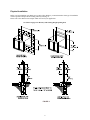
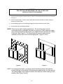
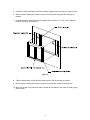
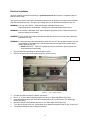
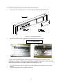
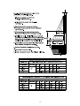
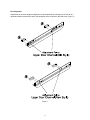
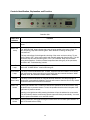
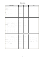
Model 275
Manual
and
Fully Automatic Electric
Drive-Thru Window
TABLE OF CONTENT
Topic
Page
Disclaimer
Serial Number Identification
Contact Sheet
Introduction
Product Information
Description
Specifications
Dimensions
Safety Information
Installation Procedures
Tools needed
Materials Needed
Physical Installation
Electrical Installation
Initial Operations and Testing
Adjustments and Calibrations
Operational Procedures
Modes of Operation
Operations
Control Identification, Explanation and Function
Maintenance
Maintenance Schedule
Daily
Monthly
Yearly
Service
Troubleshooting Guide (Cause and Effect)
Parts Lists
Complete Parts List (Description/Part Number)
Drawings - Exploded Views / Schematics
2
3
3
3
4
4
6
6
7
8
8
9
12
13
14
19
19
20
21
21
21
21
22
25
28
DISCLAIMER
READY ACCESS DISCLAIMS ANY LIABILITY FOR ANY DAMAGE OR HARM
CAUSED TO THE 275 DRIVE-THRU WINDOW, IT’S OPERATOR OR ANY OTHER
EQUIPMENT HOWEVER CAUSED IF THE 275 DRIVE-THRU WINDOW IS REPAIRED
OR SERVICED BY ANYONE OTHER THAN AN AUTHORIZED SERVICE ENGINEER
OR CONTRARY TO THE MANUFACTURERS WRITTEN INSTRUCTION CONTAINED
HEREIN.
THIS MANUAL IS INTENDED FOR USE BY THE IN-HOUSE OR AUTHORIZED FIELD
SERVICE ENGINEERS AND SALES REPRESENTATIVES
The manufacturer maintains the right to update, add or issue a new service manual at any time without
notice, thereby rendering all previous issues obsolete.
Please write the Serial Number and Installation Date for your drive-thru window in the spaces provided.
Serial Number
Date of Installation
The serial number
nameplate is located
on the post
CONTACT INFORMATION
FOR SALES AND SERVICE CONTACT
Ready Access
1815 Arthur Drive
West Chicago, Illinois 60185
Email: [email protected]
Tel: 630-876-7766
Tel: 800-621-5045
Fax: 630-876-7767
Website: www.ready-access.com
3
INTRODUCTION
The Ready Access window is quality designed to give you years of reliable, trouble-free service.
Each window is shipped pre-assembled, fully glazed and ready for installation. All Ready
Access windows are thoroughly tested prior to shipping.
The 275 Single Panel Slider Window is the perfect enhancement to the drive-thru concept,
offering unobstructed views of customer and crew.
The model 275 drive-up window comes in four versions, manual, self-closing, electric and
M.O.E.R. (Manual Open Electronic Release). The electric version is fully automatic with a
manual override in case of a power outage. The door will open and close by stepping into and
out of the light beam sensor.
The Self-Closing and M.O.E.R. versions of the 275 will be contained in a separate manual.
This attractive and economical window is ideal for a drive-thru or walk up application. The large
service opening is suitable for both large and small operations. (See Chart on Page 6)
PRODUCT INFORMATION
•
Manual or Electric Openings
The 275 Single Panel Slider keeps building costs down by offering the window in a manual
operating style. Or for those who experience heavier traffic, an electric operating style is also
available. Electric models meet health department requirements for self-closing units.
•
Ease of Operation
In a manual operation, the inside attendant pulls the door handle, to open the door. With a fully
automated operation, the operator simply steps into the presence sensor and the movable
window panel slides open. When the operator steps out of the presence sensor, the movable
window panel automatically closes. The range for the presence sensor is adjustable to specific
customer needs.
•
Quality Construction
Anodized aluminum extrusions, stainless steel and 1/4" tempered glass combine to give you an
attractive window that not only enhances building exteriors, but will not rust, pit or weather. Track
free bottom sill provides for a contaminant free surface.
•
Double Security Locks
The 275 Single Panel Slider automatically locks each time the window closes, providing security
when the window is left unattended. When the drive-thru is closed, manual security locks help
prevent outside entry.
4
•
Fully Assembled, Ready to Install
Ready Access windows are shipped completely pre-assembled and fully glazed for lower
installation costs. Normal installation takes less than two hours.
•
Three to Five Day Shipping
Ready Access will ship any standard window order in 3 to 5 days from receipt of order.
•
Warranty and Service Support
Your Ready Access window comes with a one year limited warranty on parts and labor provided
by a worldwide service organization.
STANDARD OPTIONS
•
The 275 Single Panel Slider is available in statuary bronze or clear anodized aluminum.
•
4 standard window dimensions available: (See Chart on Page # 6)
•
A retrofit kit is available for the 47 ½” wide 275 Single Panel Slider that easily upgrades the
window from a manual operation to a fully automatic operation.
•
An inside/outside stainless steel shelf is also available.
CUSTOM OPTIONS
•
Custom sizes are available in both manual and electric operations.
•
Tinted glass is available upon request.
•
Powder coat painting is available in a wide range of custom colors.
WARRANTY:
Ready Access will only accept responsibility for manufacturing defects in the
product’s construction and/or materials.
Adjustments required during installation are the responsibility of the installer or
contractor and will not be covered under warranty.
Problems caused by improper installation are the responsibility of the installer or
contractor and will not be covered under warranty.
5
SPECIFICATIONS AND PERFORMANCE
Model
Number
USA
Unit
Voltage
International
Actual
Unit
Amps
Dimensions
In Inches
WXHxD
Weight
In Shipping
Carton
275
110/120 VAC
60Hz
220/240 VAC
50/60Hz
15 A (US)
8 A (Int’l)
47½ x 43½ x 4
95 lbs
275
110/120 VAC
60Hz
220/240 VAC
50/60Hz
15 A (US)
8 A (Int’l)
47½ x 35¾ x 4
87 lbs
275
110/120 VAC
60Hz
220/240 VAC
50/60Hz
15 A (US)
8 A (Int’l)
47½ x 30 x 4
80 lbs
275
(SC)
N/A
N/A
N/A
35 ¾ x 35¾ x 4
80 lbs
Dimensions
In Inches
WxHxD
Service
Opening Size
WxH
47½ x 43½ x 4
19 ¼” x 35”
47½ x 35¾ x 4
19 ¼” x 27 ¼”
47½ x 30 x 4
19 ¼” x 21 ½”
35 ¾ x 35¾ x 4
13 ? ” x 27 ¼”
West Coast Window
15 ? ” x 27 ¼”
Glazing Rough
Opening Size
WxH
47 ¾” x 43 ¾”
1213mm x 1111mm
47 ¾” x 36”
1213mm x 914mm
47 ¾” x 30 ¼”
1213mm x 768mm
36” x 36”
914mm x 914mm
Masonry Rough
Opening Size
WxH
48” x 44”
1219mm x 1118mm
48” x 36 ¼”
1219mm x 921mm
48” x 30 ½”
1219mm x 775mm
36 ¼” x 36 ¼”
921mm x 921mm
Dimensions
4712"
[1206.50mm]
431 2"
[1104.90mm]
SEE CHART FOR OPENING SIZE
Figure 1
6
4"
[101.60mm]
Safety Information
WARNING: To avoid the risk of fire, Electric Shock or injury to persons, observe the following:
1. Before servicing or cleaning the unit, switch the power off at the mechanical switch near the unit
(Installed by an Electrician) or the electrical entry service panel/circuit breaker. (Load Center)
• OSHA LOCK OUT – TAG OUT procedures are to be observed to prevent power from being
switched on accidentally.
2. Any Installation and / or Electrical work must be done by QUALIFIED persons in accordance with
all applicable codes / standards and manufacturers recommendations and specifications.
3. DO NOT insert fingers and / or foreign objects into the Drive-Thru Window.
DO NOT block or tamper with the unit in any manner while it is in operation.
4. This product must not be used in Potentially Dangerous locations such as Flammable, Explosive
Chemical – laden environment.
7
Installation Procedures
Tools required to perform the installation
•
Electric Drill
•
Extension Cord
•
Metal Drill bits –
•
Masonry drill bit –
?” (3mm)
¼” (6mm)
½” (13mm)
1” (25mm)
•
¼” (6mm)
1” (25mm)
1½” (38mm)
Screwdrivers – Slotted and Phillips
•
Hacksaw
•
Jack / Utility Knife
•
Flat File – Coarse
•
Caulking gun
•
¼” Nut Driver
•
Masonry Hole Saw – 1” (25mm)
•
Channel Lock Pliers
•
Tape Measurer
•
Wire Cutter
•
Step Ladder
•
Level
Materials required for installation
•
Window framing, architect specified and installed in building.
(Ready Access recommended material is ?“ (3mm) x 1 ¾” (44.5mm) x 4” (102mm) hollow
aluminum tubing or glazing channel)
•
Electrical Tape
•
Wire Nuts
•
Caulking – silicone (Color specific to the color of window)
•
Connectors for conduit as required
•
Shingle type shims – as required to level and plum the window
8
Physical Installation
Before you begin installing your Ready Access Drive-Thru Window, you must determine what type of installation
will be required. Example: Wood Framing, Masonry Framing, etc.
Please refer to the details below and pick which one best fit your application.
See Chart on page 6 for Masonry and Glazing Rough Opening Sizes
FIGURE 2
9
WARNING:
TWO PEOPLE ARE REQUIRED FOR THE LIFTING AND
INSTALLATION OF THE WINDOW.
1. Confirm that the customer-supplied frame is made to accommodate the dimensions as illustrated
on page 10.
2. For the Fully Automatic – Electric units, confirm that AC power has been run and is ready for
connection to the window.
3. Check shipping carton for any shipping damage and remove window from the carton.
4. Check window for any shipping damage.
NOTE: There are two wall-mounting applications. The mounting space can be
surrounded either by sidelights (windows) or masonry. In both cases the upper
part of the window above the counter top (window sill) fits flush with the outside
of the wall. (See Figure 2) The illustrations will show the walls with the
sidelights, as this is the most common application. (Figure 3 and 4)
Figure 3
Figure 4
NOTE: If mounting the window in a masonry wall the window mounts flush with the
outside finishing of the building. Drill points are scribed directly into the masonry.
The outside edge of the mullion should be flush with the outside finishing of the
building. (See Figure 3 and 4)
10
5. Position the window and place it into the customer-supplied frame. As shown in Figure 3 and 4
6. With one person holding the window in place, level the window using the shim shingles as
needed.
7. Using the window mounting holes as a template, drill a quantity of 4 – 3/16” (5mm) diameter
holes for mounting. (See Figure 5)
Figure 5
8. Take the window back out and drill the mounting holes. Set the anchors as needed.
9. With one person holding the window in place from the outside, set the mounting screws.
10. When the window is fully secured, seal the outside of the window to the frame or building using
silicone caulk.
11
Electrical Installation
All power must be connected and wired by a qualified electrician and must be in compliance with all
state and local codes.
The incoming AC power line must be connected to the wires in the duplex box located in the top header
(Per Standard electrical code.) The green “grounding” wire is to be attached to the frame of the unit.
WARNING: Use only 110/120VAC – 60Hz source with a dedicated 15Amp circuit.
International power: 220/240VAC – 50/60Hz with a dedicated 8amp branch circuit.
WARNING: This must be a dedicated circuit. Other electrical equipment must not share the same line
from the 15Amp circuit breaker.
WARNING: Turning off the front panel rocker switches does not remove the 110/120 volts of electrical
power form the unit
WARNING: To disconnect the power completely from this unit, turn OFF the mechanical switch near the
unit (Installed by an Electrician) or the electrical entry service panel/circuit breaker panel
(Load Center) for this unit.
• OSHA LOCK OUT – TAG OUT procedures are to be observed to prevent power from
being switched on accidentally.
1.
2.
Remove the 4 screws holding on the slide channel cover.
Wire the AC source line to the duplex receptacle. (See Figure 6)
Receptacle
Figure 6
3.
4.
5.
6.
7.
8.
(Pre – 2003 models)
Connect the cable wire from the electric eye sensor.
Drill 4 - ¼” (6.5mm) holes using the masonry drill bit. (For Waist High Electric Eye Only)
Insert the plastic anchors and mount the brackets with the #10 or #12 screws. (For Waist High
Electric Eye Only)
Attach the sensor to the brackets and secure. (For Waist High Electric Eye Only)
Turn “ON” the power to the unit. (Load center circuit breaker and power switch on the “Control unit”.
Test window operations. See “Testing Procedures”.
12
For windows purchased after January 2003, follow these instructions.
1.
Remove the 2 screws holding on the AC access panel. Do not remove the slide channel cover.
Figure 6A
2.
(2003 and later models)
Wire the AC source line to the Terminal Block located in the header of the window.
AC Terminal Block
NOTE: THE GROUND WIRE (GREEN) IS ALWAYS IN THE CENTER OF THE
TERMINAL BLOCK. THE LINE (L1) IS INDICATED BY THE (RED) TAB AND THE
RETURN (NEUTRAL) IS INDICATED BY THE (WHITE) TAB.
3.
4.
Turn “ON” the power to the unit. (Load center circuit breaker and power switch on the “Control
Panel”).
Test window operations. See “Testing Procedures”.
13
Initial Window Operation
Testing Procedures
Action
Reaction
Turn the power “OFF” at the rocker switch
located on the controller unit.
Manually open and close the door several times.
When the door is opening, the “MOTOR RUN”
lamp will illuminate green. When the door is
closing, “MOTOR RUN” lamp will illuminate red.
The “POWER” lamp must illuminate during both
operations. If neither of these lamps illuminate
during any of the processes, proceed to the
“Troubleshooting” section.
Turn the power “ON” at the rocker switch located
on the controller unit.
Break the electric eye beam to open the door.
The door will open.
With the power “ON” break the electric eye beam
momentarily to open and close the door.
The door will open. They will remain in the open
position for either approximately 3.0 or 6.0
seconds before closing (Default Settings)
With the power “ON” press the “CLOSE DELAY”
button located on the controller unit once and
break the electric eye beam to open the door
The door will open and the length of time that the
door remains open will toggle between 3.0 and
6.0 seconds before closing. (Default Settings)
With the power “ON” break the electric eye beam
momentarily to open and close the door. Insert an
object at least 4” (101.6mm) wide between the
door and frame as the door closes.
The door will automatically reverse their action
(the door will open), when an object is caught
between or restricting the closing of the door.
14
Adjustments and Calibrations
SuperScan Presence Sensor Adjustment Instruction
Once the window is installed and the power is hooked up to the drive-thru window unit, you will need to
test and set the range of the presence sensor. This is done to determine the best compatibility for your
service applications. The presence sensor can be adjusted in many ways to work with different
applications.
The tools required to perform this test and adjustments are: Phillips Head Screwdriver, Straight Blade
Screwdriver and a ¼” Nut Driver.
If the drive-thru window stays open after the power is turned on and the beam break light is “ON”, the
sensor is detecting the floor or the counter top.
To adjust the presence sensor to the floor:
1. Turn the power “OFF” to the drive-thru window.
2. Remove one of the plastic end caps from the sensor body. (Preferably the left side)
3. Remove the black plastic lens cover.
Next to the “Right Eye” you will see an adjustment dial. This dial is used for adjusting the sensor to the
distance from the floor. The dial is in a clock format. The maximum distance is achieved at the 9 o’clock
position after the right eye clicks back into it’s broadest setting. The minimum distance is achieved at the
9 o’clock position before the right eye clicks back into it’s broadest setting.
NOTE: TURN THE DIAL IN A COUNTER_CLOCK_WISE FASHION ONLY.
If the Drive-Thru window stays open while standing far away from the wall or the window
closes on you while you are passing product out to the customer, then the angle of the sensor
needs to be adjusted.
Below are diagrams illustrating the different settings that can be done to adjust the distance
from the wall.
15
16
Door Alignment
Adjustments to the door height and alignment are accomplished by loosening one or both of the
adjustment blocks located at the top of the doorframe where it mounts to the slide track. (Figure 7)
Figure 7
17
Calibration:
The only calibration available on the new style DC-3 PC board is setting the close delay timer using the
dip switch package mounted near the ribbon cable connector.
Follow the chart below for changing
The CLOSE DELAY TIMER settings
The CLOSE DELAY TIMER is default set a 3 seconds.
DIP SWITCH SETTINGS
TIME IN
SECONDS
1
2
3
4
5
12
13
14
15
23
24
25
34
35
45
CLOSE DELAY
TIMER
SWITCH POSITION
2
3
4
5
OFF OFF OFF OFF
ON OFF OFF OFF
OFF ON OFF OFF
OFF OFF ON OFF
OFF OFF OFF ON
ON OFF OFF OFF
OFF ON OFF OFF
OFF OFF ON OFF
OFF OFF OFF ON
ON ON OFF OFF
ON OFF ON OFF
ON OFF OFF ON
OFF ON ON OFF
OFF ON OFF ON
OFF OFF ON ON
1
ON
OFF
OFF
OFF
OFF
ON
ON
ON
ON
OFF
OFF
OFF
OFF
OFF
OFF
The DC-2 PCB has (2) Two Potentiometers
The WINDOW SELECT DIAL is used to set the type of
door configuration for the model of the window.
The CURRENT DIAL is used to increase or decrease
the current to the motor sensetivity. This is used to set
the auto-reverse.
18
Operation Procedures
Modes of Operation:
The 275 Single Panel Slider windows have four modes of operation, Manual, Self-Closing, M.O.E.R. and
Automatic.
After installation of the Model 275 Manual or Electric Sliding window, completion of the testing procedures
and the installation of the decorative covers, the window is ready for normal use.
The Manual Mode: The opening and closing of the window is done by hand.
(DO NOT OPEN OR CLOSE THE DOOR WITH ANY UNDUE FORCE)
Manual Operations:
1. Unlock the lock bar and move it to its rest position
2. Release the manual latch and push the door open.
3. Push the door closed and allow the manual latch to reset.
4. Relock the lock bar. (At the close of the operation)
The Automatic Mode is reached by turning “ON” the main power to the window. Stepping in and out of
the sensor’s range opens and closes the door.
Automatic Operations:
1. On the controller unit, turn the power rocker switch to the “ON” position.
2. Check that the red portion of the rocker switch is visible and that the red power lamp is
illuminated
3. Break the electronic eye beam or step into the sensor beam path. The red beam break and green
motor run lamps go on.
4. Step out of the beam path and wait 3 to 6 seconds for the door to close. The red motor run lamp
and red close detect lamps will illuminate. After the door closes note that the red power lamp and
the current detect lamps are “ON”.
5. If the door does not operate correctly, go to the troubleshooting guide in this manual. If the
window still does not operate properly, then call Ready Access at
1-800-621-5045
6. The door can be operated manually by pulling the manual release located at the top of the door.
NOTE: Turn the power off to the window to prevent any damage to the PCB.
Each operator must read the operations manual before operating the unit.
19
Controls Identification, Explanation and Function
Controller Unit
Lamps and
Switches
Power Lamp
Motor Run
Lamp
Function
This lamp indicates that the power rocker switch is on and the controller is receiving
power.
The “MOTOR RUN” lamp indicates that power is being applied to the motor. When the
door is opening, lamp will illuminate green. When the door is closing, the lamp will
illuminate red.
The lamp also allows for the diagnostic checking of the motor and motor wiring. To test,
turn the power “OFF” at the rocker switch and manually open and close the door. This will
cause the lamp to illuminate either green or red. The “POWER” lamp must illuminate
during both operations. If neither of these lamps illuminate during any of the processes,
proceed to the “Troubleshooting” section.
Beam Break
Lamp
This lamp indicates that the electric eye beam or presence sensor beam has been broken
and/or the “CLOSE DELAY” timer is still timing out.
Close Detect
Lamp
This lamp is red and indicates that a “CLOSE” sequence has been initiated. It will always
light during a door closure and will go out just before the door contacts the frame. When
the lamp is out, the automatic reverse feature is disabled.
Current
Detect Lamp
This lamp is red and indicates an overload has been detected. This lamp may light on
opening but is automatically disabled. The lamp will come on when the door is fully closed
or when an obstruction has been encountered
Beam Test
Switch
Pressing the “BEAM TEST” button once will test the operations of the door without using
the electric eye or presence sensor. To test, the operator should not be in the path of the
light beam or presence sensor.
Standing in the light beam while pressing the button will put the window into a test mode.
This will make the window continuously operate (open and close) automatically. You must
turn the power off and back on to reset the window.
Close Delay
Switch
Pressing this button will toggle the length of time that the door remains open between 3.0
and 6.0 seconds before closing.
20
Maintenance
Maintenance Schedule
Scheduled maintenance should be performed on a regular basis. This is to assure proper operation and
performance of the 275 windows.
Daily
Check the sill for foreign materials and/or syrup. (Anything that might cause the window to bind up and
not operate smoothly.)
Use warm soapy water or carbonated water to clean the window.
Monthly
Follow safety procedures before opening the unit.
Check the interior of the unit for any build up of any foreign materials using a dry cloth.
NOTE: KEEP ANY LIQUIDS OFF THE INTERIOR COMPONENTS.
Clean moving parts and lubricate with silicone or Teflon spray.
NOTE: Do NOT use Grease or Oils. Do NOT lubricate the motor clutch assembly.
Yearly
Have a service technician come in and perform a maintenance check on the unit.
21
SERVICE
Troubleshooting Guide
Issue
Power switch in the
“ON” position but the
light is not illuminated.
“BEAM BREAK” lamp is
“OFF” and does not
illuminate when the
electric eye is broken.
The “CLOSE DELAY”
switch is not working
properly.
Probable Cause
Resolution
•
No power to the controller unit
Ø Main Circuit breaker is
defective or not “ON”
Ø The fuse on the power
supply is blown
Ø Main power rocker switch is
defective
Ø AC wiring is defective
•
Red Lamp/s not illuminating
•
Replace the PCB assembly cover
•
The 4 pin power connector to
the main PCB assembly is not
secure
•
Secure the connector/s to the power
supply
•
The connector/s to the rocker
switch are not secure
•
Secure the connector/s to the rocker
switch
•
Defective electric eye assembly
Ø Pressing the “BEAM TEST”
button on the controller unit
can test this. The door
should open, pause and
close. If the door operate
normally, check other
causes listed below
•
Replace the electric eye assembly
•
Loose electric eye cable from
the PCB
•
Secure the cable connector (3 or 4
pin)
•
Loose or broken wire/s in the
electric eye cable
•
Check that the electric eye cables
are secure and not broken
•
Defective lamp
•
Replace the PCB assembly cover
•
Defective PCB assembly
•
Replace the PCB assembly
•
Loose or broken connection to
the PCB Assembly
•
Secure the cable connector to the
PCB assembly or replace the control
PCB cover
•
Defective “CLOSE DELAY”
switch
•
Replace the control PCB cover
22
Ø Reset or replace the main circuit
breaker in the load center
Ø Replace the fuse on the power
supply
Ø Test rocker switch with an
ohmmeter. Replace if necessary
Ø Check AC wiring for opens.
Replace if necessary
Issue
When the beam is
broken, the door do not
open. The red “POWER”
and “BEAM BREAK”
lights and the green
“MOTOR RUN” light on
the CONTROLLER unit
are “ON”.
Probable Cause
Resolution
•
Defective motor assembly.
Ø To test for a defective motor,
open and close the door with
the power “OFF”. If the motor
is faulty, the red/green
“MOTOR RUN” lamp will not
illuminate.
•
Replace the motor assembly
•
Solenoid latch in the door is stuck
or defective
Ø To test for a defective
solenoid, manually open the
door halfway and break the
beam. The solenoid should
retract the hook and the door
should open, pause and
close. Break the beam again
to verify that the door is not
opening
•
Replace the solenoid
Ø Check the wiring to the
solenoid
•
Defective components on the
cable drive assembly. (“S” hook,
cable, spring, chain, bearing
•
Replace the defective
component.
•
Loose or broken wires
•
Secure or Replace the cable
assembly
•
Defective electric eye assembly
Ø Disconnect the cable for the
electric eye and press the
“BEAM TEST” button. If the
door operate properly the
eye is defective
•
Replace the eye assembly
•
Defective PCB assembly
Ø Disconnect the cable for the
electric eye and press the
“BEAM TEST” button. If the
door do not operate properly
the PCB is defective
•
Replace the PCB assembly
The “BEAM TEST” switch
is not working properly.
•
Loose or broken connection to
the PCB assembly
•
Secure or replace the cable
assembly
The “BEAM BREAK”
lamp is not illuminated
and the door do not open
•
Defective CONTROLLER unit
•
Replace the CONTROLLER unit
•
Defective PCB assembly
•
Replace the PCB assembly
Beam Break Lamp is
“ON” and the door open,
but they do not close.
23
Issue
Probable Cause
Resolution
•
Loose or broken wires to the
limit switches or the PCB
assembly
•
Secure or replace the cable
assembly
•
Defective “Open” limit switch
•
Replace the appropriate switch
•
Defective controller unit
•
Replace the controller unit
•
Loose or broken wires to the
limit switches or the PCB
assembly
•
Secure or replace the cable
assembly
•
Defective controller unit
•
Replace the controller unit
•
Loose or broken wires to the
limit switches or the PCB
assembly
•
Secure or replace the cable
assembly
•
Limit switch striker is loose or
out of alignment
•
Tighten and/or align the striker
plate
•
Defective controller unit
•
Replace the controller unit
The door does not fully
close and goes into
AUTOREVERSE to the
fully open position.
•
Spilled soft drink syrup residue
is under the door and on the
weather stripping of guide
block
•
Clean the weather stripping,
counter and door guides on the
bottom of the door with soda
water
Door may be sluggish in
operations.
•
Door is dragging on the
counter top
•
•
Defective motor assembly
Ø To test for a defective
motor, open and close the
door with the power
“OFF”. If the motor is
faulty, the red/green
“MOTOR RUN” lamp will
not illuminate.
•
Replace the defective motor
assembly
•
Defective CONTROLLER unit
•
Replace the CONTROLLER unit
•
Cable and chain is loose
•
Tighten cable pulley
Motor continues to run
after the door is fully
opened.
The door will not “AUTO
REVERSE” for an
obstruction when closing
and the motor continues
to run.
The “CURRENT
DETECT” lamp will not
illuminate.
The door closes fully but
open back up as soon as
the door come in contact
with each other.
The “CURRENT
DETECT” lamp will be
illuminated before the
“CLOSE DETECT” lamp
goes out.
(BEFORE REPLACING
THE MOTOR CALL
READY ACCESS FOR
FURTHER
INSTRUCTIONS)
24
Adjust the door height and
alignment
(Refer to the adjustments section
of this manual)
Parts Lists
Description
"S" Hook
Current Part Previous Part
Number
Number
20240016
N/A
Note
Angle - Reinforcement - Door - ALL
SLIDERS
Bracket, Chain & Micro Striker L/R
95119900
N/A
4pcs per door - sold in each
65181120
N/A
Bracket, Chain & Micro Striker R/L
65181110
N/A
Bumper
40010030
N/A
Bumper w/blk Lvl - 1x1
40010003
N/A
Cable - Auto Latch (Solenoid)
20112141
00651313
Cable - Eye (Waist High)
20112143
20110143
Cable - Micro Switch
20112140
N/A
Cable - Motor
20112145
20110145
Cable - Power
20112142
20110142
Cable & Chain Assy
85182000
65182001
Cable & Chain Assy ( New Chassis )
85001800
N/A
Cable, BEA Sensor to PCB (New
Chassis)
Clutch Assy - Kit - BO-10, 131, 275
20112104
N/A
85152700
65152701
Control Housing L-R - M.O.E.R.
85100820
N/A
Control Housing R-L - M.O.E.R.
85100810
N/A
Cover ( Inside ) New Style - Bronze
65110401
N/A
Cover ( Inside ) New Style - Champ
65110403
N/A
Cover ( Inside ) New Style - Clear
65110402
N/A
Doors
Door guide
Call manufacturer for part number
00651190
00651186
Door Guide Replacement Kit (Both Pcs) 85003400
N/A
Door Handle Kit - (275 SC)
85197000
65197001
Electric Chassis L/R - New Style 2003
(chassis)
Electric Chassis R/L - New Style 2003
(chassis)
Electric Eye/Reflector Kit -waist level
operation
Electric Panel - BRZ
85002120
N/A
New Style 2003 (chassis)
85002110
N/A
New Style 2003 (chassis)
85000200
00651144
Not MOER or 275 after 2/99
66122401
N/A
Electric Panel - CHMP
66122403
N/A
Electric Panel - CLR
66122402
N/A
Eye Switch Retrofit
84000300
N/A
25
Description
Flat Washer
Current Part Previous Part
Number
Number
10230108
N/A
Fuse - .5A / 250VAC
20110229
N/A
Glass Support
00650272
N/A
Handle - Manual Release - 275 L/R
New Style 2003
Handle - Manual Release - 275 R/L
Handle Kit - Manual Release - L/R
85002320
N/A
85002310
85186620
N/A
65186620
Handle Kit - Manual Release - R/L
85186610
65186610
Housing - Elect Eye
00650929
N/A
Latch Spring
00650269
N/A
Lock Bar - Lower - Swing Brkt
65023601
N/A
Lock Bar Kit - Bronze
85197101
65197101
Lock Bar Kit - Champ
85197104
N/A
Lock Bar Kit - Clear
85197102
65197102
Lock Bar Kit - Powder
85197103
N/A
Motor & Clutch Assy
85186700
65186701
PC Board - DC3 as of 12/14/01
85002001
Power Receptacle
20110241
N/A
Power Supply 120 V
85001300
65168001
Power Supply ( elec chassis only )
85001400
N/A
Power Supply Int'l ( elec chassis only )
85001700
N/A
Power Supply Int'l , B/O1,2,4,275 Int'l
85001600
N/A
Pulley-Kilrol (cable)
20200142
N/A
Rivet
10180009
N/A
Rivet For Door Guide
10180024
N/A
Roller Block - Banana Slot
20010012
N/A
Roller Block Replacement Kit - 2 Pcs
85003100
N/A
Roller Grove Bearing - SINGLE
ROLLER KIT
Round Closing Door Guide
85003600
20010030
00651834
N/A
Rubber Glass Channel
65028601
N/A
Screw 8-32X5/8 INDENTED HEX
WASH THDCT T-23 ZP
Screw for Bumper (8X1-1/2 PHILIPS
PAN HD SHT MTL)
10060074
N/A
10060086
N/A
Note
New Style 2003 (chassis)
Not MOER
26
2002 old style prior to Jan 1,
2003
2002 old style prior to Jan 1,
2003
New Style - 2001
Includes 4- 10010107, 220010030
Screw for inside cover, sensor striker
Current Part Previous Part
Number
Number
10010114
N/A
Screw Kit for 275 Adustable Track
85000700
N/A
Screws for Door Guide (Need 4)
10060087
N/A
Screws w/lock washers for roller blocks 10010107
N/A
Screws w/lock washers for roller grv brg 10010150
N/A
Sensor Assy - BEA - 275-E /starting
2/5/99 Ser# 68024
Sensor Assy - BEA - M.O.E.R.
85100701
N/A
85100700
N/A
Sensor Striker
65151101
N/A
Shoulder Screw for Manual Release
10010204
N/A
Silicone Caulk - 8 oz - Aluminum
80050029
N/A
Silicone Caulk - 8 oz - Bronze
80050020
N/A
Solenoid & Hook Assy for Electric
Chassis L/R
Solenoid & Hook Assy for Electric
Chassis R/L
Solenoid & Hook Assy L/R
85002920
N/A
New Style 2003 (chassis)
85002910
N/A
New Style 2003 (chassis)
85150520
65150502
Solenoid & Hook Assy R/L
85150510
65150501
Description
Spring - Compression (Motor & Clutch) 20060026
N/A
Spring & Ball Knob Kit (3 ea. kit)
85000300
00650284
Spring Kit - Door Handle
85197300
65197301
Striker Plate - Microswitch
65111600
N/A
Striker Plate for Handle order 2 Pop
Rivets
Switch - LIMIT FOR CHASSIS
95183600
N/A
85002200
N/A
Switch - Micro
20110281
N/A
Symmetrical Top Track.
95110700
N/A
W. COAST LOCK BAR KIT - BRZ
85002701
N/A
Washer - Clutch
10230104
N/A
Weather Strip Kit - BO-2,4,10, 275
85104000
65104001
Wired Switch Cover - Bronze
65184701
N/A
Wired Switch Cover - Champagne
65184703
N/A
Wired Switch Cover - Clear
65184702
N/A
27
Note
P/N 10180009 seperately
Drawings
Exploded Views
Page
Part Number
If Applicable
Description
29
N/A
30
85002110
Header Assembly R/L – Electric Chassis – Exploded
31
85186700
Motor and Clutch Assembly (w/ Bracket Detached)
31
85152700
Clutch Assembly – Exploded View
32
85150510 / 520
Solenoid and Hook Assembly – Pre Jan 2003
32
85002910 / 920
Solenoid and Hook Assembly – Post Jan 2003
32
85197000
Door Handle Kit – Exploded View
32
85003600
Roller Grove Bearing
33
N/A
Window Frame – Exploded View
34
N/A
Door Assembly – Exploded View
N/A
Wiring Layout
Header Assembly Pre 2003 – Exploded View
Schematics
35
28
REF
ID #
PART
NUMBER
REF
ID #
PART
NUMBER
1
85186700
DESCRIPTION
Motor & Clutch Assy
7
20200142
DESCRIPTION
Kilrol Pulley
2
85152700
Clutch Assy
8
65184701
Control Cover BR
3
20110281
Micro switch
8
65184702
Control Cover CL
4
85182000
Cable and Chain Assy
9
85002001
Control PCB Assy
5
20110241
Receptacle
10
85150510
6
85001300
120V Power Supply
Solenoid and Hook Assy
R/L
*6
85001600
220V Power Supply
(Int'l)
10
85150520
Solenoid and Hook Assy
L/R
29
REF
ID #
PART
NUMBER
REF
ID #
PART
NUMBER
5
20220003
DESCRIPTION
AC Terminal Block
1
85002910
1
85002920
6
20110281
Micro switch
2
85001400
7
20200142
Kilrol Pulley
*2
85001700
8
85001800
Cable and Chain Assy
85002001
220V Power Supply
(Int'l)
Control PCB Assy
3
9
85002120
Electric Chassis – L/R
4
85186700
Motor & Clutch Assy
9
85002110
Electric Chassis – R/L
DESCRIPTION
Solenoid and Hook Assy
R/L
Solenoid and Hook Assy
L/R
120V Power Supply
30
31
Solenoid and Hook Assembly
Pre January 2003
R/L
85150510
L/R
85150520
Solenoid and Hook Assembly
Electric Chassis Models
After January 2003
L/R
85002920
R/L
85002910
20010012
Mounting Block
85003100
Roller Bearing/Block Kit
85003600
Roller Grove Bearing Kit
85197000
Door Handle Kit
275 Manual and Self-Closing
32
REF
ID #
PART
NUMBER
REF
ID #
PART
NUMBER
1
85000700
DESCRIPTION
Adjustment Screw Kit
3
85197104
DESCRIPTION
Lock Bar Kit Champ
2
40010030
Bumper
4
85003400
Door Guide Kit
3
85197102
Lock Bar Kit CL
5
95183600
85197101
Lock Bar Kit Br
Door Handle Striker
Plate
3
33
REF
ID #
PART
NUMBER
1
65181120
1
65181110
2
65181910
2
65181920
3
20010012
DESCRIPTION
Chain and Micro Switch
Bracket L/R
Chain and Micro Switch
Bracket L/R
Solenoid Striker Plate
L/R
Solenoid Striker Plate
R/L
Block (Banana Slot)
4
85003600
Roller Grove Bearing
34
REF
ID #
PART
NUMBER
5
10010204
6
85186610
6
85186620
7
Call MFGR
8
85197000
DESCRIPTION
Shoulder Screw
Manual Release Handle
R/L Assy
Manual Release Handle
L/R Assy
Door Assembly
Door Handle Kit
Manual and Self-Closer
35
Ready Access, 1815 Arthur Drive, West Chicago, Illinois 60185, Tel: 630-876-7766, Tel: 800-621-5045
Fax: 630-876-7767, Email: [email protected], Website: www.ready-access.com
36
3/06 275 SM 3-06