1
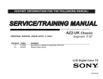
HISTORY
Model Name: KDL-32/40BX400
SERVICE MANUAL
Click on Page Number to display details of change
Date
Part Number
9-883-479-01
Original Manual
2010.10
9-883-479-02
2010.12
9-883-479-03
How to reset (OSD Menu errors) (P8)
Add Screw Part Number (Base / Stand) (P18)
2010.01
Description of Revisions
Version
1.0
2.0
3.0
AZ1-N(5-2) CHASSIS
SERVICE MANUAL
MODEL
KDL-32BX400
MODEL
DEST
AEP / UK
KDL-40BX400
DEST
AEP / UK
RM-ED022
--
TABLE OF CONTENTS
Section Title Page
1. GENERAL
Caution................................................................. 3
Specifications....................................................... 4
Connectors . ......................................................... 7
Self Diagnosis...................................................... 8
2.
DISASSEMBLY
2-1. Rear Cover Removal . ............................................ 2-2. Stand Assy Removal .............................................. 2-3. Speaker Bracket Removal....................................... 2-4. Loudspeaker Removal............................................ 2-5. Under Cover Removal ........................................... 2-6. Static Converter Board Removal............................ 2-7. BEN Board Removal ............................................. 2-8. H2LS Board Removal............................................. 2-9. HLR Board Removal.............................................. 9
9
9
9
10
10
10
10
10
3.
SERVICE MENUS
3-1. How to enter the Service Mode ........................... 3-2. Service Menu Structure ....................................... 3-2-1. Service General Menu................................... 3-2-2. White Balance Adjustment............................ 3-2-3. OSD Service Menu ....................................... 3-2-4. Country Selection.......................................... 3-2-5. Factory Reset ................................................ 3-3. TT Mode .............................................................. 11
11
11
11
12
12
12
13
Section Title Page
4. DIAGRAMS
4-1. Block Diagram .................................................... 14
4-2. Circuit Board Location . ...................................... 15
5.
EXPLODED VIEWS
5-1. Chassis . ............................................................... 16
5-2. Bezel Assy & Stand Assy..................................... 18
5-3. Rear Cover Assy & Power Supply Cords . .......... 19
6. PARTS LIST .................................................................
20
WARNING !!
AN ISOLATION TRANSFORMER SHOULD BE USED DURING ANY
SERVICE WORK TO AVOID POSSIBLE SHOCK HAZARD DUE TO
LIVE CHASSIS, THE CHASSIS OF THIS RECEIVER IS DIRECTLY
CONNECTED TO THE POWER LINE.
SAFETY-RELATED COMPONENT WARNING !!
COMPONENTS IDENTIFIED BY SHADING AND MARKED ON
THE EXPLODED VIEWS AND IN THE PARTS LIST ARE CRITICAL
FOR SAFE OPERATION. REPLACE THESE COMPONENTS WITH
SONY PARTS WHOSE PART NUMBERS APPEAR AS SHOWN IN
THIS MANUAL OR IN SUPPLEMENTS PUBLISHED BY SONY.
--
SECTION 1 GENERAL
CAUTION
Lead Free Soldered Boards
example
The circuit boards used in these models have been processed using
Lead Free Solder. The boards are identified by the LF logo located
close to the board designation e.g. H1 etc [ see example ]. The
servicing of these boards requires special precautions to be taken as
outlined below.
Lead Free Solder material must be used to comply with environmental requirements of new solder joints. Lead Free Solder is available
under the following part numbers :
Partnumber
Diameter
Remarks
7-640-005-19
0.3mm
0.25Kg
7-640-005-20
0.4mm
0.50Kg
7-640-005-21
0.5mm
0.50Kg
7-640-005-22
0.6mm
0.25Kg
7-640-005-23
0.8mm
1.00Kg
7-640-005-24
1.0mm
1.00Kg
7-640-005-25
1.2mm
1.00Kg
7-640-005-26
1.6mm
1.00Kg
Due to the higher melting point of Lead Free Solder the soldering iron tip temperature needs to be set to 370 degrees centigrade. This
requires soldering equipment capable of accurate temperature control coupled with a good heat recovery characteristics.
For more information on the use of Lead Free Solder, please refer to http://www.sony-training.com
UK PLUG WARNING
WARNING (UK Models only)
The flexible mains lead is supplied connected to a B.S. 1363 fused
plug having a fuse of the correct rating for the set. Should the fuse
need to be replaced, use a fuse of the same rating approved by ASTA
to BS 1362,, ie one that carries the ASA
T mark.
IF THE PLUG SUPPLIED WITH THIS APPLIANCE IS NOT SUITABLE
FOR THE OUTLET SOCKETS IN YOUR HOME, IT SHOULD BE CUT
OFF AND AN APPROPRIATE PLUG FITTED. THE PLUG SEVERED
FROM THE MAINS LEAD MUST BE DESTROYED AS A PLUG WITH
BARED WIRES IS DANGEROUS IF ENGAGED IN A LIVE SOCKET.
How to replace the fuse.
Open the fuse compartment with
a screwdriver blade and replace
the fuse.
FUSE
When an alternative type of plug is used, it should be fitted with the
correct rating fuse, otherwise the circuit should be protected by the
same rating fuse at the distribution board.
LCD PANEL CAUTION
Whilst working on this product, it is not recommended to lay the TV set face down when powered up, as this can result in panel problems.
If it is necessary to power up the TV set when face down, the time should be minimised as much as possible.
--
SPECIFICATIONS
Model name
KDL46EX4xx
KDL-40BX4/ KDLEX4/NX5xx 37EX4xx
KDL-32BX3/
KDLBX4/EX3/EX4/ 26EX3xx
NX5xx
KDL22EX3xx
System
Panel System
LCD (Liquid Crystal Display) Panel
TV System
Depending on your country/region selection
Analogue: B/G/H, D/K, L, I
Digital: DVB-T, DVB-C
Colour/Video System
Analogue: PAL, PAL60 (only video input), SECAM, NTSC3.58, NTSC4.43 (only video input)
Digital: MPEG-2 MP@ML/HL, H.264/MPEG-4 AVC [email protected], [email protected]
Channel Coverage
Analogue: 46.25 - 855.25 MHz
Digital: VHF/UHF
Sound Output
10 W + 10 W (RMS)
8W+8W
(RMS)
5W+5W
(RMS)
Input/Output jacks
Aerial
75 ohm external terminal for VHF/UHF
/
AV1*
/
AV2* 2
1
21-pin scart connector including audio/video input, RGB input, S-Video input, and Analogue TV audio/video
output.
21-pin scart connector including audio/video input, RGB input, S-Video input, and audio/video output.
COMPONENT IN
Supported formats: 1080p, 1080i, 720p, 576p, 576i, 480p, 480i
Y: 1 Vp-p, 75 ohms, 0.3V negative sync/P B /C B : 0.7 Vp-p, 75 ohms/
PR /CR : 0.7 Vp-p, 75 ohms
COMPONENT IN
Audio input (phono jacks)
HDMI IN 1, 2, 3, 4
Video: 1080p, 1080p24, 1080i, 720p, 576p, 576i, 480p, 480i
Audio: Two channel linear PCM
32, 44.1 and 48 kHz, 16, 20 and 24 bits, Dolby Digital
PC (see page 6)
Analogue audio (minijack) (HDMI 1 only)
AV3
Video input (phono jack)
AV3
Audio input (phono jacks)
DIGITAL AUDIO
OUT (OPTICAL)
Digital optical jack (Two channel linear PCM, Dolby Digital)
Audio output (Left/Right) (phono jacks)
PC IN
PC Input (15 Dsub) (see page 6)
G: 0.7 Vp-p, 75 ohms, non Sync on Green/B: 0.7 Vp-p, 75 ohms/
R: 0.7 Vp-p, 75 ohms, H/V Sync: TTL level
PC audio input (minijack)
i
Headphones jack
USB port
CAM (Conditional Access Module) slot
Power and others
Power Requirements
220–240 V AC, 50 Hz
Screen Size (measured
diagonally)
46 inches /
40 inches /
37 inches /
Approx. 117 cm Approx. 102 cm Approx. 94 cm
Display Resolution
1,920 dots (horizontal) × 1,080 lines (vertical) (KDL-46EX4xx, KDL-40BX4/EX4/NX5xx, KDL-37EX4xx,
KDL-32BX4/EX4/NX5xx)
1,366 dots (horizontal) × 768 lines (vertical) (KDL-32BX3/EX3xx, KDL-26EX3xx, KDL-22EX3xx)
--
32 inches / Approx. 26 inches /
81 cm
Approx. 66 cm
22 inches /
Approx. 55 cm
Model name
KDL46EX4xx
Power
in “Home”/ 142 W
consumption “Standard”
mode
in “Shop”/
“Vivid”
mode
183 W
Standby Power
Consumption*3
0.19 W
Off mode Power
Consumption
0.18 W
Average anual energy
consumption* 4
207 kWh
Dimensions (with stand) 112.7 x 71.1 x
29.4 cm
(w × h × d)
KDL-32BX3/
KDLBX4/EX3/EX4/ 26EX3xx
NX5xx
KDL22EX3xx
110 W
95 W
74 W
52 W
39 W
144 W (KDL40NX5xx)
146 W (KDL40EX4/BX4xx)
120 W
93 W (KDL32BX4/EX4/
NX5xx)
94 W (KDL32BX3/EX3xx)
62 W
46 W
161 kWh
139 kWh
108 kWh
76 kWh
57 kWh
102.3 x 66.5 x
92.1 x 59.9 x
31.0 cm (KDL25.1 cm
40NX5xx)
99.6 x 63.5 x 25.0
cm (KDL40BX4xx)
99.2 x 63.5 x 25.0
cm (KDL40EX4xx)
82.5 x 55.4 x 26.0
cm (KDL32NX5xx)
80.4 x 53.2 x 22.0
cm (KDL-32BX3/
BX4xx)
80.0 x 53.2 x 22.0
cm (KDL-32EX3/
EX4xx)
102.3 x 62.8 x
92.1 x 56.4 x 9.8
10.0 cm (KDLcm
40NX5xx)
99.6 x 59.8 x 9.9
cm (KDL40BX4xx)
99.2 x 59.8 x 10.0
cm (KDL40EX4xx)
82.5 x 51.7 x 10.2 67.2 x 42.3 x 9.9 55.1 x 36.7 x 8.2
cm (KDLcm
cm
32NX5xx)
80.4 x 49.7 x 9.6 cm
(KDL-32BX3/
BX4xx)
80.0 x 49.7 x 9.7 cm
(KDL-32EX3/
EX4xx)
(with stand) 20.4 kg
22.4 kg (KDL40NX5xx)
15.6 kg (KDL40BX4xx)
15.9 kg (KDL40EX4xx)
13.6 kg
15.5 kg (KDL32NX5xx)
10.7 kg (KDL32BX3/BX4xx)
11.0 kg (KDL32EX3/EX4xx)
8.8 kg
6.6 kg
(without
stand)
19.2 kg (KDL40NX5xx)
13.6 kg (KDL40BX4xx)
13.9 kg (KDL40EX4xx)
11.6 kg
13.0 kg (KDL32NX5xx)
9.2 kg (KDL32BX3/BX4xx)
9.5 kg (KDL32EX3/EX4xx)
7.3 kg
6.0 kg
(without
stand)
Mass
KDL-40BX4/ KDLEX4/NX5xx 37EX4xx
112.7 x 67.4 x
10.2 cm
18.1 kg
* 1 AV1 outputs available only for analogue TV.
* 2 AV2 outputs watching screen (except PC, HDMI, Component, USB).
* 3 Specified standby power is reached after the TV finishes necessary internal processes.
* 4 4 hours a day and 365 days a year.
Design and specifications are subject to change without notice.
--
67.2 x 45.9 x
22.0 cm
55.1 x 40.2 x
21.5 cm
PC Input Signal Reference Chart for PC IN
Signals
Horizontal (Pixel) Vertical (Line)
Horizontal
frequency
(kHz)
Vertical
Standard
frequency (Hz)
VGA
640
480
31.5
60
VGA
SVGA
800
600
37.9
60
VESA Guidelines
XGA
1024
768
48.4
60
VESA Guidelines
WXGA
1280
768
47.4
60
VESA
WXGA
1280
768
47.8
60
VESA
WXGA
1360
768
47.7
60
VESA
SXGA
1280
1024
64
60
VESA
UXGA
1600
1200
75
60
VESA
HDTV
1920
1080
67.5
60
EIA
• This TV’s PC input does not support Sync on Green or Composite Sync.
• This TV’s PC input does not support interlaced signals.
• This TV’s PC input supports signals in the above chart with a 60 Hz vertical frequency.
PC Input Signal Reference Chart for HDMI IN 1, 2, 3 and 4
Signals
Horizontal (Pixel) Vertical (Line)
Horizontal
frequency
(kHz)
Vertical
Standard
frequency (Hz)
VGA
640
480
31.5
60
VGA
SVGA
800
600
37.9
60
VESA Guidelines
XGA
1024
768
48.4
60
VESA Guidelines
WXGA
1280
768
47.4
60
VESA
WXGA
1280
768
47.8
60
VESA
WXGA
1360
768
47.7
60
VESA
SXGA
1280
1024
64
60
VESA
--
CONNECTORS
21 Pin Connector (SCART)
Pin No
AV-1
AV-2
Signal
Signal Level
1
•
•
Audio Output B
(Right)
Standard Level: 0.5V rms
Impedance: less than 1KΩ*
2
•
•
Audio Input B
(Right)
Standard Level: 0.5V rms
Impedance: more than 10KΩ*
3
•
•
Audio Output A
(Left)
Standard Level: 0.5V rms
Impedance: less than 1KΩ*
4
•
•
Ground (Audio)
5
•
•
Ground (Blue)
6
•
•
Audio Input A (Left)
Standard Level: 0.5V rms
Impedance: more than 10KΩ*
7
•
•
Blue Input
0.7V +/- 3dB, 75Ω, positive
8
•
•
Function Select
(AV control)
High State (9.5~12V): AV mode
Low State (0~2V): TV mode
Impedance: more than 10KΩ*
Capacitance: less than 2nF
9
•
•
Ground (Green)
10
-
•
AV Link
11
•
•
Green Input
12
-
•
Open
13
•
•
Ground (Red)
14
•
•
Ground (Blanking)
•
•
Red Input
0.7V +/- 3dB, 75Ω, positive
•
•
S signal Chroma Input
0.3V +/-3dB, 75Ω, positive
16
•
•
Blanking Input
(Y Signal)
High State (1~3V)
Low State (0~0.4V)
Impedance: 75Ω
17
•
•
Ground
(Video Output)
18
•
•
Ground
(Video Input)
19
•
•
Video Output
1V +/-3dB, positive sync 0.3V (-3+10dB)
•
•
Video Input
1V +/-3dB, positive sync 0.3V (-3+10dB)
•
•
Video Input Y
(S Signal)
1V +/-3dB, positive sync 0.3V (-3+10dB)
•
•
Common Ground
(Shield)
1
2
3
4
5
6
7
8
9
10
11
12
13
14
15
16
17
18
19
20
21
0.7V +/- 3dB, 75Ω, positive
15
20
21
HDMI Connector
19
17
18
15
16
13
11
14
9
12
7
10
5
8
3
6
4
1
2
Pin No
Signal Assignment
Pin No
Signal Assignment
1
TMDS Data2+
11
TDMS Clock Shield
2
TMDS Data2 Shield
12
TMDS Clock-
3
TMDS Data2-
13
CEC
4
TMDS Data1+
14
Reserved (N.C. on device)
5
TMDS Data1 Shield
15
SCL
6
TMDS Data1-
16
SDA
7
TMDS Data0+
17
DDC/CEC Ground
8
TMDS Data0 Shield
18
+5V power
9
TMDS Data0-
19
Hot Plug Detect
10
TMDS Clock+
15 Pin D Sub Connector (PC)
5
4
10
15
3
9
14
2
8
13
1
7
12
6
11
--
Pin No
Signal Assignment
Pin No
Signal Assignment
Pin No
Signal Assignment
1
Red Output
6
Red Return
11
Monitor IDO in display
2
Green Output
7
Green Return (Ground)
12
DCC Serial Data
3
Blue Output
8
Blue Return (Ground)
13
Horizontal Sync
4
Unused
9
+5V DC
14
Vertical Sync
5
Ground
10
Sync Return (Ground)
15
DCC Serial Clock
AZ1-N SELF DIAGNOSTIC SOFTWARE
The identification of errors within the AZ1-N chassis is triggered in one of two ways :- 1: Busy or 2: Device failure to respond to IIC. In the
event of one of these situations arising the software will first try to release the bus if busy (Failure to do so will report with a continuous flashing LED) and then communicate with each device in turn to establish if a device is faulty. If a device is found to be faulty the relevant device
number will be displayed through the LED (Series of flashes which must be counted).
LED Error Codes and Descriptions
Number of LED
Flashes
Error Description
Checked
Action
02
Power Supply Protection error.
In normal and factory mode.
Goes into standby.
03
Audio error.
In normal and factory mode.
Goes into standby.
04
Balancer error.
In normal and factory mode.
Goes into standby.
05
Panel Error & Panel ID error
In normal and factory mode.
Goes into standby.
06
Inverter error.
In normal and factory mode.
Goes into standby.
13
NVM error.
In initialisation state.
Adds error to error menu.
14
I2C error.
In normal and factory mode.
Adds error to error menu.
15
Tuner error.
In initialisation state.
Adds error to error menu.
16
DVB-T/C Demod error.
In initialisation state.
Adds error to error menu.
18
USB error.
In normal and factory mode.
Adds error to error menu.
19
CI error.
In normal and factory mode.
Adds error to error menu.
Ver 2.0 Resetting Error Codes (OSD Service Menu)
1. If Software version of the set is older than M8R31 (M8.311), update to latest version.
2. Power Off / Power ON.
3. Apply TT19.
4. Apply TT08. TV switches off and then restarts.
5. Confirm error had disappears.
Note: TT19 is necessary if Factory mode is not enabled.
When Factory Mode is enabled “F” is shown on top right of the screen in TT mode.
-8-
SECTION 2 DISASSEMBLY
2-1. Rear Cover Removal
=>
>= 1
3/4
1
=>
>= 3/4
=>
2
=>
1
1
=>
1
=>
>= 1
>=
1
2-2. Stand Assy Removal
1/4 =>
>= 1/4
=>
=>
>= 2
>= 1
Remove the rear cover fixing screws indicated and then
carefully pull the ‘Rear Cover’ away from the back of the
TV set.
Remove the 4 stand fixing screws indicated and lift the TV set
up and away from the ‘Stand Assy’.
Screw Part number(s) and Description(s)
Screw Part number(s) and Description(s)
1) 2-580-640-01
2) 7-685-648-79
3) 2-580-595-01
4) 4-159-298-01
SCREW, +BVTP2 4X16 SCREW, +BVTP 3X12 SCREW, +PSW M3X12 SCREW, +PSW M4X10 >=
>=
2-580-608-01
SCREW, +PSW M5X16
(32” = 10pcs, 40” = 8pcs)
(32/40” = 2pcs)
(32” = 2pcs)
(40” = 4pcs)
2-3. Speaker Bracket Removal
2-4. Loudspeaker Removal
Screws
Screw
To remove the ‘Speaker Bracket’ remove the 1 screw
circled. Then gently pull the ‘Speaker Bracket’ away from
the back of the TV set.
To remove the ‘Loudspeaker’ first disconnect the
loudspeaker connectors and then remove the 2 screws
circled. Finally gently pull the ‘Loudspeaker’ out of the
speaker bracket.
--
2-5. Under Cover Removal
2-6. Static Converter Board Removal
Screw
Screws
To remove the ‘Under Cover’ first remove the ‘Rear Cover’
(See Sec 2-2-1) and then the ‘Stand Assy’ (See Sec 2-2-2).
Then remove the 1 screw circled and gently pull the
‘Under Cover’ away from the back of the TV set.
To remove the ‘Static Converter’ board disconnect all
connectors and then remove the 4 screws circled and ease the
board gently away from the back of the TV set.
Screw Part number(s) and Description(s)
Screw Part number(s) and Description(s)
2-580-640-01 SCREW, +BVTP2 4X16
2-580-592-01 SCREW, +PSW M3X8
2-7. BEN Board Removal
2-8. H2LS Board Removal
Clips
To remove the ‘H2LS’ board disconnect the 1 connector and
release the 3 clips circled and ease the board gently away
from the TV set.
2-9. HLR Board Removal
Screws
To remove the ‘BEN’ board disconnect all connectors and
then remove the 4 screws circled and ease the board gently
away from the back of the TV set.
Clips
Screw Part number(s) and Description(s)
To remove the ‘HLR’ board first remove the ‘Speaker Bracket’
(See 2-2-3), then disconnect the 1 connector on the ‘HLR’
board and release the 2 clips circled and ease the board gently
away from the back of the TV set.
2-580-592-01 SCREW, +PSW M3X8
- 10 -
SECTION 3 SERVICE MENUS
3-2. Service Menu Structure
3-1. How to enter the Service Mode
Service adjustments to this model can be performed using the
supplied Remote Commander (See front cover).
1. Turn on the power to the TV set.
2. Press the following sequence of buttons on the Remote
Commander.
i+
5
+
(ONSCREEN
SCREEN
(ON
DISPLAY)
DISPLAY)
(DIGIT
5)
(DIGIT 5)
(VOLUME
+)
(VOLUME +)
The following descriptions show the items that can be
viewed and/or adjusted using the Service Menu.
3-2-1. Service General Menu
TV I/
(TV)
(TV STANDBY)
The following menu appears on the screen when you enter
the ‘Service General Menu’ (See Pic.2). This menu allows
you to view the product information, set the TV into Aging
Mode and perform Software Upgrade to the TV set.
Pic.2
Service General Menu
3. The following menu appears on the screen (See Pic.1).
MIPS Version
M 8.017
SBY Version
NVM Version
Upgrader Version
Pic.1
Operation Hours
Factory Service Menu
Model ID
Service General Menu
MIPS Version
Aging Mode
White Balance Adjustment
SBY Version
Serial No
OSD Service Menu
NVM Version
Software Upgrade
Country Selection
Upgrader Version
Set-up
Factory Reset
Operation Hours
Errors
Model ID
Aging Mode
Aging Time Settings
Serial No
3-2-2. White Balance Adjustment
Software Upgrade
Set-up
Errors
-------------------- Store
-------------------- Exit
4.
5.
6.
7.
8.
9.
Move to the corresponding adjustment item using the
‘ ’ or ‘ ’ arrow buttons on the Remote Commander.
Press the ‘
’ arrow button to enter into the required menu
item.
Adjust the data value using the ‘ ’ or ‘ ’ arrow buttons on
on the Remote Commander.
To go back at any time press the ‘Return’ button on the Remote
Commander.
Ensure you return to the top level menu, shown above in
Pic 1, and press the Green button on the Remote
Commander to Store all the adjustments.
Press the Red button or ‘Menu’ button on the Remote
Commander to quit the Service Mode when all adjustments
have been completed.

After carrying out the service adjustments, to prevent the customer accessing the ‘Service Menu’ switch the TV set
OFF and then ON again.
- 11 -
The following menu appears on the screen when you enter
the ‘White Balance Adjustment’ menu (See Pic.3). This menu
allows adjustment of the TV picture levels. These adjustments
are set during manufacture and should not normally require
further adjustment.
Pic.3
White Balance Adjustment
WB init
WB Adjustment Level
Red Value
Green Value
Blue Value
Save Level
End Adjustment
3-2-3. OSD Service Menu
The following menu appears on the screen when you enter
the ‘OSD Service Menu’ (See Pic.4). This menu allows
viewing and adjustment of the AGC and viewing of the
Sound Status.
3-2-4. Country Selection
The following menu appears on the screen when you enter
the ‘Country Selection’ menu (See Pic.5). Using this menu
the destination country of the TV can be set.
Pic.4
Pic.5
OSD Service Menu
Country Selection
DVB Basic
United Kingdom
Open
DVB Detail
Ireland
Close
Panel Backlight
Nederland
Sound Status
Belgie/Belgique
Luxembourg
France
Italia
Schweiz/Suisse/Svizzera
Deutschland
Osterreich
3-2-5. Factory Reset
Selection of ‘Factory Reset’ (See Pic.6) allows the TV to be
reset to factory shipping condition. This will restore all
settings to those which were contained in the TV on first
shipment.
Pic.6
Factory Service Menu
Service General Menu
Start Now:
White Balance Adjustment
OSD Service Menu
Country Selection
Factory Reset
-------------------- Store
-------------------- Exit
- 12 -
3-3. TT MODE
The TT modes described below are available by selecting the two
relevant digits. You can exit the ‘TT Mode’ by entering 00, by
pressing the ‘Analog’ or the ‘Digital’ button, by switching the TV
set into stand-by mode, or by powering the TV set off.
00
'TT'modeoff
03
Setvolumeto35%
04
Setvolumeto50%
05
Setvolumeto65%
06
Setvolumeto80%
07
Ageingmodeon
08
ShippingCondition
09
WBLevelsCheck
11
Panel_idA
12
Panel_idB
15
Speaker_idA
16
Speaker_idB
19
Factorytogglemode(ON/OFF)
27
CBAmodetoggle(ON/OFF)
31
ECSmodetoggle(ON/OFF)
32
SetDVB-Tchanneltable
33
SetDVB-Cchanneltable
36
FullHDHDMIEDIDWrite
37
WXGAHDMIEDIDWrite
41
Re-initialiseNVM
43
SelectDualSound"A"
44
SelectDualSound"B"
45
SelectDualSound"Mono"
46
SelectDualSound"Stereo"
48
SetNVMasnon-virgin
49
SetNVMasvirgin
51
ClearauthenticatedCAMHistory
52
Clearserviceshunningcache
53
Enable/DisableDVB-Cmanualtuning
75
SetCentredBalance
76
SetVolumetoMax
77
SetVolumetoMin
78
SetBalanceFullLeft
79
SetBalanceFullRight
81
DigitalBERDisplay
84
TSCIPathThrough
87
FrontPanelButtonTest
89
LEDTest
92
TSCIPathThroughWithReedSolomonOff
Note :

To place the Remote Commander in ‘TT Mode’ press the
following buttons together for approximately five seconds.
i+
5
+
(EXTERNAL
INPUT)
(DIGIT
(VOLUME
(ON
SCREEN
(DIGIT
5) 5)
(VOLUME
+) +)
(ONSCREEN(DIGIT5)(VOLUME+)(TV)
DISPLAY)
DISPLAY)

To use the Remote Commander in ‘TT Mode’ press the
‘Rewind’ button on the Remote Commander twice.
Rewind Button
TT will then appear in the bottom right hand corner of the TV.

To take the Remote Commander out of ‘TT Mode’ press the
same buttons together for approximately five seconds.
- 13 -
4-1. BLOCK DIAGRAM
BEN
CI
Si-TU
SUT_AE102T
Aerial/Cable
HDMI1
HDMI2
HDMI3
HDMI4
Demodulator
CXD2817R-T4
㧔DVB-T/C㧕
NAND FLASH
NAND01G
W3B2CN6F
HDMI
EQ/SW/EDID
TDA19997
USB
DDR2
512Mb
DDR2
512Mb
PNX8543M2
PC Audio
SCART1
32,26,22
WXGA CCFL
46,40,37,32
FHD CCFL
HLR
Light
Sensor
MAIN CHIP
PC
PANEL
BH1690FVC
NVM
SCART2
3a-2/5-0
Component
Control Button
CV-Side
Line Out
HP Out
IR
LED
Gxx
AUDIO
Buffer
CXA3813N
Power Supply
AUDIO
D-Amp
TPA3110D2
Opt. Out
- 14 -
5-2
H2LS
Key
4-2.
BOARD
LOCATION
5-2. CIRCUIT
CIRCUIT
BOARD
LOCATION
Reference Information
RESISTOR
STATIC CONVERTER
C
C
NBEN
H
: NON FLAMMABLE CEMENT
CVM Board
RW
: NON FLAMMABLE WIREWOUND
J
S1 Board
A
D2 A
H2LS
A Board
A2
: ADJUSTMENT RESISTOR
COIL
LF-8L
: MICRO INDUCTOR
CAPACITOR
TA
: TANTALUM
PS
: STYROL
PP
: POLYPROPYLENE
PT
: MYLAR
MPS
: METALIZED POLYESTER
MPP
: METALIZED POLYPROPYLENE
ALB
: BIPOLAR
ALT
: HIGH TEMPERATURE
ALR
: HIGH RIPPLE
A1
D
All capacitors are in µF unless otherwise noted.
pF : µµF 50WV or less are not indicated except for
electrolytic types.
Indication of resistance, which does not have one for
rating electrical power, is as follows.
•
•
Chip resistors are 1/10W
All resistors are in ohms.
k = 1000 ohms, M = 1000,000 ohms
•
: nonflammable resistor.
•
: fusible resistor.
•
: internal component.
•
: panel designation or adjustment for repair.
•
•
•
•
: NON FLAMMABLE FUSIBLE
: NON FLAMMABLE METAL OXIDE
Note : The components identified by shading
Pitch : 5mm
Electrical power rating : 1/4W
•
: NON FLAMMABLE CARBON
FUSE
RB
Note :
•
: SOLID
FPRD
RS
4-3. SCHEMATIC DIAGRAMS AND
5-3. SCHEMATIC DIAGRAMS AND
PRINTED
WIRINGBOARDS
BOARDS
PRINTED WIRING
•
•
: METAL FILM
RC
VM
HLR
D1
RN
and marked
are critical for safety.
Replace only with the part numbers
specified in the parts list.
Note : Les composants identifiés par une trame et
par une marque
sont d'une importance
critique pour la sécurité. Ne les remplacer
que par des pièces de numéro spécifié.
specified.
All variable and adjustable resistors have
characteristic curve B, unless otherwise noted.
All voltages are in Volts.
Readings are taken with a 10Mohm digital mutimeter.
Readings are taken with a color bar input signal.
Voltage variations may be noted due to normal production
tolerences.
•
: B + bus.
•
: B - bus.
•
: RF signal path.
•
: earth - ground.
•
: earth - chassis.
Note : The components identified by mark
contain
confidential information.
Strictly follow the instructions whenever the
components are repaired and/or replaced.
- 15 -
SECTION 5
EXPLODED VIEWS
NOTE :
Non-serviceable items with no part number and no description are not stocked because they are not
required for routine service.
The construction parts of an assembled part are indicated
with a collation number in the remarks column.
Items marked “*” are not stocked
since they are seldom required for
routine service. Some delay should
be anticipated when ordering these
items.
5-1. CHASSIS
1
2
3
4
5
6
6
10
7
9
Note : The components identified by mark contain confidential information.
Strictly follow the instructions when ever the components are repaired and/or replaced.
REF.NO.
1
£
£
2
3
4
5
6
PART.NO
1-811-059-11
1-811-060-11
1-474-208-11
1-474-201-21
A-1763-564-A
4-166-268-22
8-597-735-00
1-858-364-11
DESCRIPTION
REMARK
LCD PANEL (S32TSP)
32 inches
LCD PANEL (S40TSP)
40 inches
STATIC CONVERTER(TV)
32 inches
STATIC CONVERTER(TV)
40 inches
BEN BOARD, COMPLETE
BRACKET, SIDE JACK
UNIVERSAL SIL-TU SUT-AE102T
LOUDSPEAKER(4.5x12.5cm)
8
REF.NO.
7
8
9
10
- 16 -
PART.NO
4-164-507-01
4-166-119-11
A-1763-559-A
4-164-509-02
4-166-123-11
4-164-506-01
4-166-120-11
DESCRIPTION
BRACKET, SP (32L)
BRACKET, SP (40L)
HLR BOARD, COMPLETE
COVER, UNDER (32)
COVER, UNDER (37)
BRACKET, SP (32R)
BRACKET, SP (40R)
REMARK
32 inches
40 inches
32
40
32
40
inches
inches
inches
inches
5-1. CHASSIS Cont.
12
13
14
15
16
11
17
22
REF.NO.
11
12
13
14
15
16
PART.NO
A-1765-913-A
4-164-279-01
1-821-834-12
1-822-637-11
1-822-579-31
1-822-581-22
DESCRIPTION
REMARK
H2LS BOARD, COMPLETE
BRACKET, VESA (S)
USB CONNECTOR
HDMI CONNECTOR
CARD CONNECTOR (PCMCIA CARD)
MULTIPLE PHONO JACK 4P
REF.NO.
17
18
19
20
21
22
- 17 -
PART.NO
1-822-638-11
1-842-087-11
1-822-524-31
1-822-954-11
1-822-523-11
1-822-580-21
21
20
19
18
DESCRIPTION
REMARK
HDMI CONNECTOR
D SUB CONNECTOR
PHONO JACK 2P
PHONO BLOCK, OPTICAL OUT
PHONO JACK 5P
CONNECTOR DUAL SCART
5-2. BEZEL ASSY & STAND ASSY
51
52
53
55
54
REF.NO.
51
52
PART.NO
X-2547-156-1
X-2547-123-1
4-158-400-11
4-171-690-01
DESCRIPTION
BEZEL (CON32) ASSY
BEZEL (CON40) ASSY
COVER, NECK (M3B)
COVER, NECK (ML3B)
REMARK
32 inches
40 inches
32 inches
40 inches
REF.NO.
53
54
55 Ver 3.0
- 18 -
PART.NO
4-158-354-01
4-171-686-01
X-2541-850-1
X-2541-851-1
4-159-298-01
DESCRIPTION
REMARK
NECK (M3B)
NECK (ML3B)
BASE (M3B) ASSY
BASE (ML3B) ASSY
SCREW, +PSW M4X10
32
40
32
40
inches
inches
inches
inches
5-3. REAR COVER ASSY & POWER SUPPLY CORDS
101
102
UK MODELS ONLY
104
103
REF.NO.
101
102
PART.NO
X-2547-155-1
X-2547-124-1
*3-106-546-51
DESCRIPTION
REMARK
REAR COVER (CON32) ASSY 32 inches
REAR COVER (CON40) ASSY 40 inches
ECS COVER
REF.NO.
103 £
104 £
- 19 -
PART.NO
DESCRIPTION
REMARK
1-837-454-11 POWER-SUPPLY CORD (AEP) 32/40 inches
1-837-455-11 POWER-SUPPLY CORD (UK) 32/40 inches
SECTION 6
PARTS LIST
PARTS LISTING TABLE OF CONTENTS
Page
ACCESSORIES AND CONNECTORS :
.................................................................................................... 21
REMOTE COMMANDER :
................................................................................................... 21
Note:
To ensure safety and reliability it is Sony policy that boards should not be repaired in the field, as a result
all boards are regarded as non service items for exchange only and are not indicated in the parts list of this
service manual.
Note : Items marked “*” are not stocked since they are seldom required for routine service.
Some delay should be anticipated when ordering these items.
- 20 -
REF.NO.
PART.NO
DESCRIPTION
REMARK
REF.NO.
ACCESSORIES AND CONNECTORS
32 INCHES
1-837-622-11 FLEXIBLE FLAT CABLE (TCON-BEN(CN4301))
*1-910-060-73 CONNECTOR ASSY 15P (G2L(CN6401-BEN(CN6006))
*1-910-060-76 MULTI HARNESS SPEAKER BEN(CN6007/7901)-
HLR-H2LS-SPEAKERS)
*1-910-060-77 CONNECTOR ASSY 14P (G2L(CN6402)-INVERTER)
40 INCHES
1-837-624-11 FLEXIBLE FLAT CABLE (TCON-BEN(CN4301))
*1-910-060-80 CONNECTOR ASSY 15P (G2M(CN6401-BEN(CN6006))
*1-910-060-83 MULTI HARNESS SPEAKER BEN(CN6007/7901)-
HLR-H2LS-SPEAKERS)
*1-910-060-84 CONNECTOR ASSY 14P (G2M(CN6402)-INVERTER)
INSTRUCTION MANUALS
*4-168-148-11 INSTRUCTION MANUAL (UK) ENGLISH
*4-168-148-21 INSTRUCTION MANUAL (AEP) GERMAN/SPANISH/
FRENCH/ITALIAN/DUTCH/PORTUGUESE
*4-168-148-31 INSTRUCTION MANUAL (AEP) BULGARIAN/CZECH/
DANISH/FINNISH/GREEK/HUNGARIAN/NORWEGIAN/
POLISH/ROMAINIAN/SWEDISH/SLOVAK/TURKISH
REMOTE COMMANDER
1-487-828-11 REMOTE COMMANDER (RM-ED022)
- 21 -
PART.NO
DESCRIPTION
REMARK
Sony Corporation
9-883-479-03
Sony UK
Service Promotions Dept.
English
10LP7100-1
Printed in U.K.
© 2010.12