1
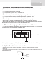
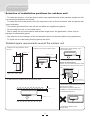
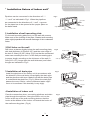
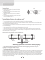
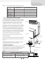
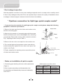
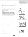
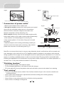
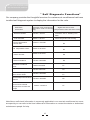
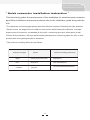
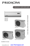
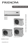
INSTALLATION AND REPAIR GUIDE
Split Wall-Mounted Air Conditioner
Foreword
Air conditioners are units that should have the professional technicians do the
installation for you.
This Instruction Guide is the universal-purpose version for the models of split
wall-mounted air conditioners manufactured by our Co. The appearance of the
units that you purchase might be slightly different from the ones described in
the Guide, but it does not affect your proper operations and usage.
Please read carefully the sections corresponding to the specific model you
choose, and keep the Guide properly so as to facilitate your reference at later
time.
CONTENTS
Selection of installation positions for indoor unit
Selection of installation positions for outdoor unit
Installation fixture of indoor unit
Installation fixture of outdoor unit
Ordinary pipelines connection & Air purging
Pipelines connection for Split type quick coupler model
Pipelines connection for Whole-Unit type quick coupler model
Connection of power cable
Finishing touches and test running
Is the unit installed correctly?
Self diagnosis functions
Quick connector installation instruction
Installation Guide
1
2
3
4
4
6
7
8
8
9
10
11
12
INSTALLATION & REPAIR GUIDE
Split Wall-Mounted Air Conditioner
*Selection of installation positions for indoor unit*
* To be installed at the position where the air delivered from the unit can reach every corner of
the room;
* To avoid being affected by the outdoor air;
* To avoid blockage to the air inlet or outlet of the unit;
* To avoid too much oil smoke or steam;
* To avoid possible generation, inflow, lingering or leakage of flammable gases;
* To avoid high-frequency facilities (such as high frequency arc welders, etc.);
* To avoid the places where acid solutions are frequently used;
* To avoid the places where some special sprayers (sulfides) are frequently used.
* Not to install on top of the musical instruments,TV,computer etc.valuable appliance.
* Not to install a fire alarming device near the air outlet of the unit (during operation, the fire alarm
device might be erroneously triggered by the warm air from the unit);
* Make sure of enough space for installation and maintenance.
* To take into consideration the operational convenience and safety in installation, it is recommended
to ensure enough space between the unit and the walls.
Ceiling
Above 100mm(4")
Right side: 150mm (6")
and above from wall
Left side: 150mm(6")
and above from wall
Wall hanging plate
2300mm(7'6")
and above
ground
Attention:If there are some additional function devices to install on the air conditioner,Be
sure add to the installation space for the function devices.
* Height limits of indoor and outdoor units.
* Either the indoor unit or the outdoor unit can be higher, but the height difference must comply the stated
requirements.
* Try to reduce the bending of the piping line as much as possible so as to avoid possible negative impacts upon the
performances of the units.
Indoor unit
5m(16'5")max.
1
outdoor
unit
INSTALLATION & REPAIR GUIDE
Split Wall-Mounted air conditioner
*Selection of installation positions for outdoor unit*
* To install the outdoor unit at the places which can stand the load of the machine weight and will
not cause big vibrations and noises;
* To install the unit at the places not to be exposed to rain or direct sunshine, and the places with
good ventilation;
* The noises generated from the unit will not affect the neighboring places;
* Do not install the unit on non-metal frame;
* Not to install the unit at the places where there might occur the generation, inflow, stay or
leakage of inflammable gases;
* Pay attention to the drainage of the condensed water from the base plate during operations;
* To avoid the air outlet being directly against the wind.
Detailed space requirements around the outdoor unit
2. When the front (air outlet) is open
3. When there are obstacles only in
the front (air outlet)
500mm(1'8") min
1. When there are obstacles above
the unit
100mm(4") min
200mm(8") min
300mm(1') min
Space for maintenance
Shown as in the following figure. Keep
the maintenance space in front of the
unit.
500mm(1'8") min
500mm(1'8") min
200mm(8") min
200mm
(8")min
500mm
(1'8")min
4. When there are obstacles at the front and rear sides.
100mm(4") min
Space for maintenance
5. When there are obstacles all around
the unit on four sides.
Although the top side is open, the
installation is not to be done if there
are obstacles all around.
1000mm(3'4") min
* At least two sides should
be kept open.
2
INSTALLATION & REPAIR GUIDE
Split Wall-Mounted air conditioner
* Installation fixture of indoor unit*
Pipelines can be connected in the directions of****
Fig.1
****and* as indicated in Fig.1. When the pipelines
are connected to the directions of***and*, a groove
for the pipes has to be opened at the proper place on
the base stand.
*Left outlet
*Left rear outlet
*Right outlet
*Rear outlet
*Bottom outlet
1.Installation of wall-mounting plate
Fix the wall-mounting plate firmly on the wall with screws.
Make sure of the leveling of the plate. Slanted wall-mounting
plate might jeopardize the smooth discharge of the condensed
water.
2.Drill holes on the wall
Drill holes at places slightly below the wall-mounting plate,
with hole diameter of 65mm(2-3/5") and the outer edge of
the hole 5-10mm(1/5-2/5") lower (Fig.2) so that the condensed
water can smoothly flow out. Cut the wall penetrating pipe
to proper length according to the thickness of the wall (35mm(1/10-1/5") longer than the wall thickness) and insert
the pipe as indicated in Fig.2.
3.Installation of drain pipe
Fig.2
Fix with a tape
5-10mm lower
(1/5-2/5")
Wall cap
Wall pipe
Wall
Interior
Exterior
Fig.3
Install the pipelines of the indoor unit in accordance with
the direction of the wall holes. Wrap tightly the drain pipe
and the pipelines with tape. Make sure that the drain pipe
is underneath the pipelines. (Fig.3) (When the drain pipe
passes the room interior, some condensed water might
occur to its surfaces if the humidity is very high).
Pipelines of indoor unit
Drain pipe
Rear pipe
4.Installation of indoor unit
Pass the connection wires, connecting pipelines and drain
pipe through the wall hole. Hang the indoor unit on the
hooks at the top of the wall-mounting plate so that the
hooks at the bottom of the indoor unit match the hooks of
the wall-mounting plate. (Fig.4)
Fig.4
Top hooks
Hook supports
Bottom hooks
3
INSTALLATION & REPAIR GUIDE
Split Wall-Mounted air conditioner
Inspections:
Fig.5
a. Check if the hooks at the top and bottom
are firmly fixed.
b. Check if the position of the master unit is
properly leveled.
c. The drain pipe should not curve upward
(Fig.5).
d. The drain pipe should be at the lower part
of the wall pipes (Fig. 5).
Connecting pipe
Connecting wires
Wall pipe
Drain pipe
Drain pipe
* Installation fixture of outdoor unit*
* Try to ship the product to the installation location in its original package;
* As the gravity center of the unit is not at the installation center, special caution should be taken
when using hoisting cables to lift it up;
* During shipping, the outdoor unit must not be slanted to over 45 degrees (Do not store the unit
in a horizontal way).
* Use expansion bolts to fix the mounting supports on the wall;
* Use bolts and nuts to fix the outdoor unit firmly on the supports and keep on the same level;
* If the unit is installed on the wall or at the rooftop, the supports have to be firmly fixed so as to
resist earthquake or strong wind.
Dimensions for parallel units installations
300mm(1')min
* Ordinary pipelines connection & Air purging *
* The following ordinary pipelines connection and air purging procedures are just
suitable for non-quick coupler model.
*Ordinary pipelines connection
No dust ,foreign articles,air or moisture should be allowed to enter the air conditioning system.Careful
attention should be paid when pipeline connection for outdoor unit is made.Try to avoid repeated
curves as much as possible,otherwise hardening or cracks might be caused to the copper pipes.
Suitable wrenches should be used when the pipeline connection is done so as to ensure appropriate
torque(refer to following torque Table 1).Excessive torque might damage the joints while too little
torque might lead to leakage.
4
INSTALLATION & REPAIR GUIDE
Split Wall-Mounted air conditioner
Table 1 Torque based upon the wrench to be used
Outer diameter of
copper pipe
Tightening torque
6.35(1/4")
160kgf.cm(63kgf.inch)
9.52(3/8")
300kgf.cm(118kgf.inch)
12.7(1/2")
500kgf.cm(197kgf.inch)
550kgf.cm(216kgf.inch)
15.88(5/8")
750kgf.cm(295kgf.inch)
800kgf.cm(315kgf.inch)
19.05(3/4")
1200kgf.cm(472kgf.inch)
Strengthened tightening torque
200kgf.cm(79kgf.inch)
350kgf.cm(138kgf.inch)
1400kgf.cm(551kgf.inch)
*Air purging with vacuum pump
1.Check that pipelines connection have been properly
connected,remove the charging port cap,and connect
Indoor unit
the manifold gauge and the vacuum pump to the
charging valve by service hoses as shown Fig.6.
2.Open the valve of the low pressure side of manifold
gauge,then,run the vacuum pump.Vacuum the indoor
unit and the connecting pipes until the pressure in
them lowers to below 1.5mmHG(The operation time
for vacuuming is about 10 minutes).When the desired
vacuum is reached,close the valve of the low pressure
of the manifold and stop the vacuum pump.
Outdoor unit
3.Disconnect the service hoses and fit the cap to
3-way valve
the charging valve.
2-way valve
4.Remove the blank caps,and fully open the spindles
of the 2-way and 3-ways valves with a service valve
wrench.
Manifold gauge
Union nut
5.Tighten the blank caps of the 2-way and 3-ways
Blank cap
valves,applying the above torque Table 1.
Lo
*Adding refrigerant
Pressure gauge
Hi
Charging Valve stem
port
Refrigerant must be added if the piping measures more
than 5 metres(16'5") in length.This operation can only
Service hose
be performed by a professional technician,for the
additional amount,see the table 2 below.
Vacuum pump
Table 2
Additional refrigerant amount
Liquid pipe diameter
6.35(1/4") Liquid pipe diameter: 9.52(3/8")
(piping length-5)mx30g
or (piping length-16)ftx0.3oz
(piping length-5)mx65g
or (piping length-16)ftx0.7oz
5
Fig.6
INSTALLATION & REPAIR GUIDE
Split Wall-Mounted air conditioner
*Gas leakage inspection
After the pipieline connection is done,use a leakage inspection device or soap suds to carefully check
if there is any leakage at the joints.This is an imporant step to ensure the quality of installation.Once
a leakage is detected,proper treatment should be taken immediately.
* Pipelines connection for Split type quick coupler model*
* If you purchase the machine for split type quick coupler model,please adopt the following
pipeplines connection procedures:
1.Remove the dust caps from the indoor and outdoor units,
and the connecting pipe.
2.Align the joint counter of connecting pipe with the proper
indoor and outdoor joint conic surfaces,tighten the connecting
nut manually.Then,make it secure with a wrench as shown
Fig.7
Fig.7 ,applying to above torque Table 1.
3.Remove the two valve core caps from the outdoor unit.
4.Turn on the high and low pressure valve cores with an
socket wrench,then tighten the two valve core caps of the
outdoor unit (Fig.8).
Quick coupler
(wrapping with insulating cotton)
5.Finally ,wrap the hot insulating cotton around the joints
Low pressure valve
of indoor and outdoor units.
Valve core cap
High pressure valve
Fig.8
*
Notes on installation of quick coupler:
1.Connecting pipe bending minimum radius parameters
Table 3 Minimum bending radius
(Table 3)
Normial
diameter(mm)
2.Quick coupler assembly and disassembly limit:
DN8(5/16")
the assembly and disassembly times are inadvisably
more than 7.
6
DN10-12
(1/2")
DN14-16
(5/8")
Minimum bending
radius(mm)
80(3")
100(4")
150(6")
cooling capacity
2100~2300W
(7000~8000BTU)
2500~5100W
(9000~18000BTU)
6100~7000W
(22000~24000BTU)
INSTALLATION & REPAIR GUIDE
Split Wall-Mounted air conditioner
* Pipelines connection for Whole-Unit type quick coupler model*
* If you purchase the machine for Whole-Unit type quick coupler model,please adopt the
following pipeplines connection procedures:
STEP 1
* Remove two screws on the maintance plate with
Fig.9
a screwdriver and take off the plate,then remove the
dust caps on both indoor male coupler and outdoor
female coupler,See Fig.9.
Screw
STEP 2
* Press the projecting section of outdoor female
Outdoor Valve for gas
leaking(rear end)
coupler backward with a little force by the thumb to
make inner hooks open, and then you can easily take
Dust Cap
Fig.10
Projecting section
out the outdoor valve for gas leaking by the other
hand,See Fig.10.
STEP 3
* In the same way,press the projecting section
backward,then connect the indoor male coupler to
Outdoor female coupler
(With movable sheath)
the outdoor female coupler,See Fig.11.
Outdoor Valve for gas leaking
STEP 4
* Close the key lever of indoor male coupler to the
Fig.11
horizontal position,then indoor and outdoor refrigerant
will be circulating,and now you can obvioulsy hear the
sound of inner air flowing ,See Fig.12.
STEP 5
Outdoor female coupler
* Connect the outdoor quick cable coupler with
Indoor male coupler
indoor quick cable coupler,See Fig.13.
STEP 6
Fig.12
* Finally,Re-install the mainteance plate back into its
place,See Fig.14.
As for the outdoor valve for gas leaking and the dust
caps,you can preserve them for future possible use on
Key lever
the removal of your air conditioner.
7
INSTALLATION & REPAIR GUIDE
Split Wall-Mounted air conditioner
Fig.13
Fig.14
Wrap with ethylene tapes
Outdoor quick cable coupler
Indoor quick cable coupler
* Connection of power cable*
1.Remove the drawer of the outdoor unit.
Fig.15
2.Non-quick coupler:connect the indoor power and control
wire pressing plate
wires with the matched outdoor wires in accordance
with the electric schematic diagram and make sure
that the connection is firmly done(Fig.15.)
Quick coupler:directly connect quick cable couplers with
Drawer
screw
indoor and outdoor quick cable couplers after disassembly
of the outdoor unit connecting box cover(Fig.16.)
3.Use a press plate to fix the wires firmly,and re-install
the drawer.
4.Optional steps:In some cooling and heating models,you
Fig.16
Fig.17
should connect the indoor wire connector with outdoor
probe wire connector for defrosting,see Fig.17.
Indoor wire connector
Outdoor probe wire connector for defrosting
Note:Do not connect the wires in a wrong way,otherwise electric malfunctions will be caused and
even damages to the units will occur.The appliance shall be installed in accordance with national
wiring regulation.If the supply cord is damaged,it must be replaced by the manufacturer or its service
agent or a similarly qualified person in order to avoid a hazard.The plug shall be accessible after
installing the appliance.If the model have not plug that a switch which have a contact separation of
at least 3 mm in all poles shalled be added in fixed wiring.
* Finishing touches *
* wrap the piplines tightly with ethylene tapes.
* Fix the wrapped pipelines on the exterior wall with clamps.
* Fill in the gaps left over by the pipeline hole and wall hole to prevent rain-water from entering.
* Test running*
* Connect to the power source,check if the function selection keys on the remote controller are
working properly.
* Check if the room temperature adjustments and timer settings are working properly.
* Check if the drain is smooth.
* Check if there is any abnormal noise or vibration during operation.
* Check if there is leakage of refrigerant.
8
INSTALLATION & REPAIR GUIDE
Split Wall-Mounted air conditioner
* Is the unit installed correctly? *
*Suitable Installation Position
*Isn't there anything which prevents ventilation or obstructs operation in front of the indoor unit ?
Do not install the unit following place .
*Inflammable gases may leak .
*Oil splashes a lot .
*In case where the unit is used in such places as poisonous or sultry gases are generated or seaside
district exposed to sea breezes corrosion may cause malfunction . Consult with your distributor .
*Air conditioner body and remote controller must be I m(39-3/4") or more away from a TV or a radio.
Drain the dehumidified water from the indoor unit to a place which drains well .
*Pay attention to operation noise
*When installing the unit , choose a place which can stand the weight of the unit well and does
not increase the operation noise or vibration . Especially where there is a possibility that vibration
be transmitted to the house , fix the unit by inserting attached vibration -proof pads between the
unit and fittings .
*Choose the place where hot air and operation noise from the outlet of the outdoor unit do not
annoy the neighborhood .
*Things left near the outlet and inlet of the outdoor unit cause malfunction or increased
operation noise . Do not leave obstacles near the outlet and inlet .
*If irregular sound is heard during operation , consult with your distributor .
*Inspection and Maintenance
*According to the service conditions and operating environment , the inside of the air conditioner
will become dirty after several seasons (3 to 5years ) of service , resulting in decreased operating
performance .Inspection and maintenance are recommended in addition to usual cleaning (The
air conditioner can be used for a longer period and without anxiety .)
*As to inspection and maintenance , consult your dealer or any one of business offices of
dealing companies .(Service charge is required in this case .)
*We recommend to perform inspection and maintenance during an off seasons.
9
INSTALLATION & REPAIR GUIDE
Split Wall-Mounted air conditioner
* Self
Diagnosis Functions *
Our company provides the thoughtful services for customer,air conditioners had been
installed self diagnosis system to display the information for the units.
Self-check
information
Self-check code of luminotron/
Digital self-check code/
(Self-check code of running (Polychrome screen self-check code)
lamp)
Defrost indication
Flicker 1 time/1s
Indicates "dF"or Heating icon
flash
Anti cold wind
Flicker 1 time/1s
Fan motor picture not running
Room temperature
sensor fault
Coil temperature sensor
Flicker 1 times/8s
Flicker 2 times/8s
E2
E3
Indoor fan fault
Flicker 3 times/8s
outdoor feedback
Flicker 6 times/8s
External feedback
fault
Flicker 7 times/8s
E7
Flicker 3times/8s
E0
Outdoor tube temperature sensor faults
Flicker 4 times/8s
E1
(EEPROM)communication
failures
Flicker 6 times/8s
E6
Open the door fault
North American
environment outside
temperature erceeds the
scope
Flicker 1 times/1s
E8
E5
FF
Note:Above self check information is commonly applicable in our most air conditioners,but some
are special,you can refer to the User's Manual for information or contact the dealer or authorized
maintenance people for help.
10
INSTALLATION & REPAIR GUIDE
Split Wall-Mounted air conditioner
* Quick
connector installation instruction
*
This sheet only guides the requirements of the installation for stainless quick connector
pipe.Other installation requirements please refer to the installation guide along with the
unit.
*To expand the connecting pipe,please hold one side then expand it following the right direction.
*Please insure the angles have a radian at some extent while intalling the stainless soft pipe.
Angels need to be around, not bended.(to the quick connecting spot and drilled point of wall.
*Please fix the stainless soft pipe while installing because the connecting pipes are soft, so that
prevent them from getting bended or stretched.
*The minimum bending radius are as follows:
Stainless soft pipe
Minimum bending radius(mm)
Model
* Eight
Twenty-one,Twenty-five
Eighty(mm)
* Ten
Thirty-five
One hundred(mm)
* Thirteen
One hundred and fifteen(mm)
fifty-one
11
INSTALLATION & REPAIR GUIDE
Split Wall-Mounted air conditioner
* Installation
To keep the allowed
bending radius,please
make the packed soft
pipes vertical for
expanding.
Guide *
Please do not expand
only one side of the
packed soft pipes.
Please make use of
semicircle pulley to keep
the allowed bending
radius.
Extremely bending could
damage the pipes.
Please use twisting
wheel to avoid improper
bending.
Over length soft pipes
will lead to irregular
bending.
Please use rigid elbow
to keep the bending
radius while soft pipes
operating.
Undersize bending will
damage the soft pipe.
Please Keep the
minimum bending radius
while installing.
Short soft pipes will
have them bending
undersize,it's not
allowed.
12