1
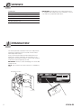
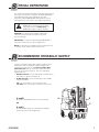
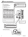
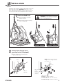
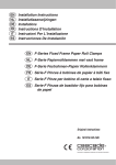
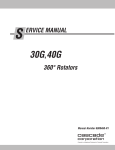
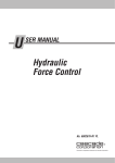
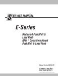
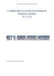
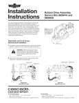
I NSTALLATION INSTRUCTIONS and PERIODIC MAINTENANCE F-Series Fixed Frame Paper Roll Clamps Manual Number 674510-R5 cascade corporation Cascade is a Registered Trademark of Cascade Corporation C ONTENTS Introductioni Special Definitions 1 Recommended Hydraulic Supply 1 Truck Requirements 2 Installation3 Periodic Maintenance 9 I IMPORTANT: Field alterations may impair performance or capability and could result in loss of warranty. Consult Cascade for any required modifications. NTRODUCTION This manual provides installation instructions and periodic maintenance requirements for Cascade F-Series Fixed Frame Paper Roll Clamps. In any communication about the Roll Clamp refer to the product I.D. number stamped on the nameplate. If the nameplate is missing, the numbers can be found stamped on the front of the faceplate top or side. IMPORTANT: All hoses, tubes and fittings on F-Series Roll Clamps are JIC. NOTE: Specifications are shown in both U.S. and (Metric) units. Nameplate Locations c SERIAL NUMBER CATALOG NUMBER ADDITIONAL EQUIPMENT ADDITIONAL EQUIPMENT ADDITIONAL EQUIPMENT RC0720.eps i LIFT TRUCK ATTACHMENT 674870 60F-RCP-459 WEIGHT LBS. ATTACHMENT CAPACITY POUNDS INCH LOAD AT CENTER CAPACITY OF TRUCK AND ATTACHMENT COMBINATION MAY BE LESS THAN ATTACHMENT CAPACITY SHOWN ABOVE. CONSULT TRUCK NAMEPLATE. RECOMMENDED SYSTEM PRESSURE – 2000 PSI MAXIMUM SYSTEM PRESSURE – 2300 PSI FOR TECHNICAL ASSISTANCE, PARTS AND SERVICE CONTACT: 1-800-227–2233 PORTLAND, OREGON USA 70 48R 7 9 6 O 45 P C F-R 0 6 674510-R5 S PECIAL DEFINITIONS The statements shown below appear throughout this manual where special emphasis is required. Read all WARNINGS and CAUTIONS before proceeding with any work. Statements labeled IMPORTANT and NOTE are special information that is useful when servicing the attachment. WARNING - A statement preceded by a WARNING is information that should be acted upon to prevent bodily injury. A WARNING is always inside a ruled box. CAUTION – A statement preceded by CAUTION is information that should be acted upon to prevent machine damage. IMPORTANT – A statement preceded by IMPORTANT is information that possesses special significance. NOTE – A statement preceded by NOTE is information that is handy to know and may make the job easier. R ECOMMENDED HYDRAULIC SUPPLY F-Series Fixed Frame Paper Roll Clamps provide the best performance with the hydraulic supply arrangements shown below. Refer to Cascade Hose and Cable Reel Selection Guide, Part No. 212119, to select the correct hose reel for the mast and truck. The hose and fitting requirements are: • ROTATE Function – Hoses and fittings should be No. 8 with 13/32 in. (10 mm) minimum I.D. • CLAMP Function – Hoses and fittings for the CLAMP function should be: 25F – No. 6 with 9/32 in. (7 mm) minimum I.D. 38F-160F – No. 8 with 13/32 in. (10 mm) minimum I.D. A and B RH and LH THINLINE™ 2-Port Hose Reel Groups. A B OR C A and C RH THINLINE™ 2-Port Hose Reel Group and Mast Single Internal Hose Reeving Group. GA0033.eps 674510-R5 1 T RUCK REQUIREMENTS WARNING: Rated capacity of the truck/ attachment combination is a responsibility of the original truck manufacturer and may be less than that shown on the attachment nameplate. Consult the truck nameplate. Truck Relief Setting 25F, 28F (Rotate Circuit). 45-160F 2000 psi (138 bar) Recommended 2300 psi (160 bar) Maximum 38F (Clamp Circuit) 2300 psi (159 bar) Recommended 2600 psi (179 bar) Maximum Truck Flow Volume ➀ Min. ➁ Recommended Max. ➂ 5 GPM (19 L/min.) 7 GPM (26 L/min.) 10 GPM (38 L/min.) 5 GPM (19 L/min.) 5 GPM (19 L/min.) 10 GPM (38 L/min.) 12 GPM (45 L/min.) 12 GPM (45 L/min.) 15 GPM (57 L/min.) 5 GPM (19 L/min.) 7 GPM (26 L/min.) 10 GPM (38 L/min.) 77F, 90F, 100F, 10 GPM 120F (38 L/min.) 15 GPM (57 L/min.) 20 GPM (76 L/min.) 15 GPM (57 L/min.) 20 GPM (76 L/min.) 25 GPM (95 L/min.) 25F 38F Clamp Rotate 45F, 60F, 66F 130F, 150F, 160F ➀ Cascade Roll Clamps are compatible with SAE 10W petroleum base hydraulic fluid meeting Mil. Spec. MIL-0-5606 or MIL-0-2104B. Use of synthetic or aqueous base hydraulic fluid is not recommended. If fire resistant hydraulic fluid is required, special seals must be used. Contact Cascade. ➁ Flow less than recommended will result in a rotate speed less than 2 RPM. ➂ Flow greater than maximum can result in excessive heating, reduced system performance and short hydraulic system life. GA0369.eps Clean and inspect carriage bars for damage and smoothness. Repair any protruding welds or damaged notches. Carriage Mount Dimension (A) ITA (ISO) A Class II Class III Class IV Minimum Maximum 14.94 in. (380.0 mm) 18.68 in. (474.5 mm) 23.44 in. (595.5 mm) 15.00 in. (381.0 mm) 18.74 in. (476.0 mm) 23.50 in. (597.0 mm) Rotate Tilt Forward CCW Auxiliary Valve Functions Check for compliance with ANSI (ISO) standards: Hoist Down Release GA0082.eps Hoist up 2 Tilt Back Rotate CW Clamp 674510-R5 I NSTALLATION Follow the steps shown to install the Roll Clamp on the truck. Read and understand all WARNING statements. If you don't understand a procedure, ask your supervisor, or call the nearest Cascade Service Department for assistance. 1 Attach overhead hoist A Remove banding, set clamp WARNING: Check weight on nameplate of Roll Clamp and make sure overhead hoist is rated appropriately. upright on pallet. B Remove bolt-on lower mounting hooks (if equipped). A A B RC0967.ill 2 Unlock Quick-Change lower mounting hooks (if equipped) A Move hooks into unlocked position (pin in lower hole). A NOTE: Guides can be reversed to change hook-to-carriage clearance (See Step 7). Guide e CL0097.eps ® d ca s ca -1 14 55 67 C- LH lower QC Hook Pin 5/8-in. offset on top provides maximum clearance. Tighten Capscrews: CL II & III – 110 ft.-lbs. (150 Nm) CL IV 60F, 66F, 77F – 195 ft.-lbs. (265 Nm) CL IV 90F and larger – 260 ft.-lbs. (360 Nm) 674510-R5 3 I NSTALLATION 3 Preparing Hoses A Position truck carriage behind Roll Clamp. B Determine hose lengths required. C Cut hoses to length, install end fittings. INSTALLATION USING RH & LH 2-PORT THINLINE™ HOSE REELS: CAUTION: Hoses should be 2300 psi working pressure rated for all attachment functions. INSTALLATION USING RH 2-PORT HOSE REEL AND INTERNAL HOSE REEVING: Rotate CCW Rotate CCW 25F Rotate CW Rotate CW Clamp Clamp Open Open 38F-100F RC1813.eps RC1814.eps Rotate CCW Rotate CW Rotate CW Rotate CCW Clamp Clamp RC0441.eps Open Open 120F-160F RC0442.eps Rotate CW Rotate CCW Rotate CW Rotate CCW Clamp Open RC1816.eps Open 4 RC1815.eps Clamp 674510-R5 I NSTALLATION 4 Flush hydraulic supply hoses A Install hoses as shown. B Operate auxiliary valves for 30 sec. C Remove union fittings. D Install hoses to Roll Clamp fittings as shown in Step 3 above. GA0081.eps 5 Check oil level and remove rubber vent cover Newer models only 38F–160F 25F Oil level must be up to fill plug hole. Oil level must be up to fill plug hole. Remove rubber vent cover. If necessary, fill gearbox with Cascade Gear Lube 656300 or equivalent SAE 90 wt. gear lube (AGMA 'mild' 6EP Gear Oil). RR0928.eps 6 Mount Clamp on truck carriage A Center truck behind Roll Clamp. B Tilt forward and raise carriage into position. C Engage top mounting hooks with carriage. Remove rubber vent cover. NOTE: For attachments with brake drive, the fill plug hole is located on RC0139.eps the LH housing above the manifold. 25F Centering Tab 25F – Make sure the centering tab engages the center notch on top carriage bar. 38F-160F – Make sure locator tab in left hook engages closest notch on top carriage bar. D RC1817.eps Lift Clamp 2 in. (5 cm) off pallet. (Class II carriage bars and upper mounting hooks shown.) ITA Class II – 0.72–0.78 in. (18–20 mm) ITA Class III – 0.72-0.78 in. (18-20 mm) ITA Class IV – 0.72-0.78 in. (18-20 mm) Notch Engage hook locator tab in carriage notch Connect hoses to end block before clamp installation. ITA Class II – 0.32-0.36 in. (8-9 mm) ITA Class III – 0.39–0.43 in. (10–11 mm) ITA Class IV – 0.47-0.51 in. (12-13 mm) Upper Carriage Bar 674510-R5 RC0723.eps Center Spacer GA0079.eps 5 I NSTALLATION 7 Install and engage lower hooks QUICK-CHANGE TYPE (OPTIONAL) BOLT-ON TYPE Lower Carriage Bar Lower Carriage Bar Install hooks, tap tight into position. ST JU AD e ad Inspect hooks for excessive clearance. (Reverse guides to change clearance, See Step 2.) ® c as c Slide hook up to engage bar, install pin in locked position. (upper hole.) RC0148.eps 3/16 in. (16 mm) Max. RC0147.eps Tighten Capscrews: CL II & III – 110 ft.-lbs. (150 Nm) CL IV 60F, 66F, 77F – 195 ft.-lbs. (265 Nm) CL IV 90F and larger – 260 ft.-lbs. (350 Nm) 8 Connect hoses to hose terminal fittings as shown in Step 3 INSTALLATION USING RH & LH 2-PORT THINLINE™ HOSE REELS: RC0440.ill 6 INSTALLATION USING RH 2-PORT HOSE REEL AND INTERNAL HOSE REEVING: RC0765.eps 674510-R5 • Locate one stop block on the outside of each upper hook. NOTE: Stop blocks may be located vertically on each end of carriage bar if insufficient room exists outside of upper hooks. • Preheat each stop block and carriage bar weld area to 325 ° F (180 ° C). • Use AWS E7018 low hydrogen rod and weld a 1/4-in (6 mm) fillet full length on three (3) sides of each stop block. NOTE: Do not weld stop block on inside 1/16 in. (1.6 mm) Steel Stop Block Truck Upper Carriage Bar 6 mm (1/4-in.) fillet weld on three(3) sides RC0224.eps Dual Drive Brake Adjustment (if equipped) Adjustment is not necessary, the cartridge valve is factory set to provide optimum performance for your application. If the cartridge needs to be adjusted, with the truck off, do the following: • Loosen jam nut (3/8 in. Hex) on the valve cartridge. Use 1/8 in. Allen wrench to turn the adjustment screw all the way CCW. Brake Cartridge Valve W 10 RH Upper Mounting Hook • Make sure the attachment is centered on carriage. CW 9 Install stop block kit CC I NSTALLATION • Turn the cartridge adjustment screw 3/4 of a turn, CW. CAUTION: Adjusting the cartridge beyond 3/4 turn will damage the brake. • Tighten the jam nut. 674510-R5 RC4015.eps 7 I 11 NSTALLATION Cycle Clamp Functions WARNING: Make sure all personnel are clear of Clamp during testing. • • With no load, cycle all functions several times. • Clamp and rotate a maximum load, check for smoothness and normal rotation. • Check for leaks at fittings, revolving connection and cylinder rod ends. Hoist Down A C Check functions for operation in accordance with ITA (ISO) standards. B D GA0005.eps Hoist up LONG ARM (Driver's view) A Counterclockwise (CCW) B Clockwise (CW) B C Release D Clamp A D C Tilt Back ROTATE (vertical & horizontal positions only) SHORT ARM (45-degree position only) D C RC0030.eps 8 Tilt Forward A Open B Close RC0031.eps 674510-R5 I 12 NSTALLATION Split Arm Relief Pressure Adjustment, if required – Type 1 (Full Arm Travel Circuit) WARNING: Make sure all personnel are clear of the attachment during testing. IMPORTANT: Revolving connection with relief valve controlled split-arm circuit must be adjusted for proper arm movement as follows: Split Long Arm Cylinder AConfirm that the truck relief setting is between 2000–2600 psi (140–180 bar). BRotate the Clamp to the vertical roll handling position. WARNING: Before removing any hoses, relieve pressure in the hydraulic system. With the truck off, open the truck auxiliary control valve(s) several times in both directions. CInstall 5000-psi (345 bar) pressure gauges to each split long arm cylinder test port (No. 4 O-ring fitting required). DOpen the long arms. Clamp a split roll (30 in. diameter min.) or clamp-force indicator, between the short arm pad and lower split long arm pad. Build pressure until the upper arm begins to move. Release the lever and note the gauge pressure. E Rotate the Clamp 180 degrees. Repeat step D for the opposite split long arm. Both pressures should be within 50 psi (3.5 bar). If not, adjust the relief cartridge (screw out CCW) on the arm with the higher pressure to equal the arm with the lower pressure. NOTE: 1 turn = approximately 400 psi (28 bar). F At half throttle, compare the gauge pressure with truck relief pressure. Adjust both relief cartridges equally using 1/8 turn steps. Verify that the unclamped arm moves after the clamped arm stops and re-syncs upon opening. GAdjust the clamped arm pressure to approximately 200 psi (14 bar) lower than truck relief pressure. If not possible, lower relief settings equally and test until system resets. Start step F procedure again to maximize clamped arm pressure. RC0349.eps C Test Port Plug C Pressure Gauge IMPORTANT: If truck is equipped with a 3 or 4 pressure selection valve, adjust split arm relief cartridges while pressure selection valve is at its lowest supply setting. Revolving Connection Split Long Arm A HCheck that the clamp pressures are approximately equal (see step E). Tighten the jam nut on each relief cartridge. Relief (A) controls Split Long Arm A LONG ARM D SHORT ARM Split Long Arm B E 674510-R5 Relief (B) controls Split Long Arm B RC3074.eps Short Arm 9 P ERIODIC MAINTENANCE 100-Hour Maintenance WARNING: After completing any service procedure, always test the Clamp through five complete cycles. First test the Clamp empty, then test with a load to make sure the attachment operates correctly before returning it to the job. Every time the lift truck is serviced or every 100 hours of truck operation, whichever comes first, complete the following maintenance procedures: • Check for loose or missing bolts, worn or damaged hoses and hydraulic leaks. • Check contact pads edges for wear or sharp edges that could damage or tear paper rolls. Grind edges smooth. • Check contact pad pivot pins for wear. Repair or replace as necessary. Contact Pad Pivot Joints Contact Pad Edges Rotator Bearing Assembly Grease Fitting • Lubricate plungers on 180-degree stop valve (if fitted). Rotator Drive Fill Plug • Check that load-holding hydraulic system is functioning properly. Cascade Clamp Force Indicators 830141 and 832442 are available for this test. • Check decals and nameplate for legibility. 500-Hour Maintenance After each 500 hours of truck operation, in addition to the 100-hour maintenance, perform the following procedures: • Check sample of baseplate-to-bearing capscrews for proper torque value. See Technical Bulletin TB183 or Service Manual 674512 for checking and replacement procedures. • Check sample of bearing-to-faceplate capscrews for proper torque value. See Technical Bulletin TB183 or Service Manual 674512 for checking and replacement procedures. RC0749.eps Left Side • Tighten lower mounting hook capscrews to 122 ft.-lbs. (165 Nm). WARNING: A sampling of faceplate and baseplate bearing assembly capscrews must be checked for proper torque at 500 hours (see TB183). A complete inspection is required every 2000 hours. Failure to keep the capscrews tightened can result in attachment damage and serious injury. • Tighten rotator drive capscrews. See torque specs for specific models in Installation section, step 7. • Lubricate rotator bearing assembly with EP-2 grease. (Whitmore 'Omnitask' or equivalent). Rotate clamp in 90-degree increments and grease in each position. • Check rotator drive gearcase lubricant level. Lubricant should be up to bottom of fill plug hole. If necessary, fill with Cascade Rotator Drive Lubricant, Part No. 656300 or SAE 90 wt. gear lube (AGMA 'mild' 6 EP Gear Oil). Replace the plug. • Inspect all arm, frame and cylinder pivot bushings for wear. Replace if necessary. Arm, Cylinder Pivot Joints Faceplate/Bearing Assembly Capscrews (Access all through hole in baseplate) Rotator Drive Capscrews Baseplate/Bearing Assembly Capscrews • Inspect all load-bearing structural welds on arms, frame and arm pivots, and cylinder pivot areas for visual cracks. Replace components as required. 2000-Hour Maintenance After each 2000 hours of truck operation, in addition to the 100 and 500-hour maintenance, perform the following procedures: Rotator Drive Fill Plug • Check all rotation bearing capscrews for proper torque value. See Technical Bulletin TB183 or Service Manual 674512 for checking and replacement procedures. • Inspect all arm and cylinder pivot pins for wear and replace if necessary. RC0750.eps Mounting Hook Capscrews 10 674510-R5 BLANK Do you have questions you need answered right now? Call your nearest Cascade Service Department. Visit us online at www.cascorp.com AMERICAS Cascade Corporation U.S. Headquarters 2201 NE 201st Fairview, OR 97024-9718 Tel: 800-CASCADE (227-2233) Fax: 888-329-8207 Cascade Canada Inc. 5570 Timberlea Blvd. Mississauga, Ontario Canada L4W-4M6 Tel: 905-629-7777 Fax: 905-629-7785 Cascade do Brasil Rua João Guerra, 134 Macuco, Santos - SP Brasil 11015-130 Tel: 55-13-2105-8800 Fax: 55-13-2105-8899 EUROPE-AFRICA Cascade Italia S.R.L. European Headquarters Via Dell’Artigianato 1 37050 Vago di Lavagno (VR) Italy Tel: 39-045-8989111 Fax: 39-045-8989160 Cascade (Africa) Pty. Ltd. PO Box 625, Isando 1600 60A Steel Road Sparton, Kempton Park South Africa Tel: 27-11-975-9240 Fax: 27-11-394-1147 ASIA-PACIFIC Cascade Japan Ltd. 2-23, 2-Chome, Kukuchi Nishimachi Amagasaki, Hyogo Japan, 661-0978 Tel: 81-6-6420-9771 Fax: 81-6-6420-9777 Cascade Korea 121B 9L Namdong Ind. Complex, 691-8 Gojan-Dong Namdong-Ku Inchon, Korea Tel: +82-32-821-2051 Fax: +82-32-821-2055 Cascade-Xiamen No. 668 Yangguang Rd. Xinyang Industrial Zone Haicang, Xiamen City Fujian Province P.R. China 361026 Tel: 86-592-651-2500 Fax: 86-592-651-2571 Cascade Australia Pty. Ltd. 1445 Ipswich Road Rocklea, QLD 4107 Australia Tel: 1-800-227-223 Fax: +61 7 3373-7333 Cascade New Zealand 15 Ra Ora Drive East Tamaki, Auckland New Zealand Tel: +64-9-273-9136 Fax: +64-9-273-9137 Sunstream Industries Pte. Ltd. 18 Tuas South Street 5 Singapore 637796 Tel: +65-6795-7555 Fax: +65-6863-1368 Cascade India Material Handling Private Limited No 34, Global Trade Centre 1/1 Rambaugh Colony Lal Bahadur Shastri Road, Navi Peth, Pune 411 030 (Maharashtra) India Phone: +91 020 2432 5490 Fax: +91 020 2433 0881 c Cascade Corporation 2011 05-2011 Part Number 674510-R5