1
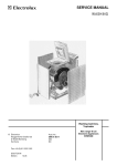
SERVICE MANUAL Compact front loaded Washing Machines (Timer controlled) © Electrolux Muggenhofer Straße 135 D-90429 Nürnberg Germany Fax +49 (0)911 323 1022 Spares Operation Ausgabe: 10.2003 DGS-TDS-N - R.Kurzke Publ.-Nr.: 599 518 355 EN Compact front loaded Washing Mashines from Torsvik Timer controlled Table of Contents General features Programs Timer function Operation principle Types of Spin 10.2003 R.K. 3 4 5 6 7 Construction Enclosure Upperframe Lowerframe Rear of machine Front panel Detergent dispenser Front hatch Hatch locking switch Washing unit with outer drum 9 9 9 10 11 11 12 12 13 Function Monitoring of spin phase for imbalance Water supply valve Level regulator Heating element NTC-Thermistor Drainage pump 14 15 15 16 16 17 Service/Accessibility Top plate Panel Hatch 18 19 20 Hatch hinge Rear ot machine Drum unit Shockabsorbers Outer drum with drum bearing 21 22 23 23 24 Troubleshootings Motor check 25 27 Diagrams 28 Washing programs table 30 Timer diagram Timer connectors 31 32 -2- 599 518 355 Controls Timer type VD55 Push button functions On/off, Rinse hold Knob/Command func. Program, Temperature Dimensions Height 670 mm Width 495 mm Depth 515 mm Tub material Carboran Drum volume 27 l Washing capacity 3.00 kg Inlet hose length 130 cm Outlet hose length 160 cm Det. dispenser type of Two chambers Cord length 170 cm 10.2003 R.K. -3- 599 518 355 10.2003 R.K. -4- 599 518 355 10.2003 R.K. -5- 599 518 355 OPERATION PRINCIPLE Traditional washing Operation 1 2 3 4 Detergent hatch Hose between detergent dispenser and outer drum Outer drum Inner drum 5 6 7 8 9 Heating element Rubber bottom, fixed to outer drum Drainage pump Circulation hose Drainage hose - The partides of soiling substances which are freed from the textile fibres by the chemical action of the detergent at the temperature of the washing water are re-moved by the flow of water through the fibres. - The reversing rotation ofthe drum causes mechamcal interaction between the parts ofthe load and the detergent solution which separates the partides from the textlies. - The water level is at such a height that the load is successively lifted from the solution by the ridges formed in the inner drum and then falls back into the solution. - The Circulation ofthe solution during the rotation ofthe drum prevents the accumulation of detergent in the rubber bottom. 10.2003 R.K. -6- 599 518 355 10.2003 R.K. -7- 599 518 355 10.2003 R.K. -8- 599 518 355 CONSTRUCTION Enclosure The enclosure consists of: - a lacquered steel sheet pressing forming the front and both sides, fixed between upper and lower CARBORAN frames - a removabie galvanized sheet steel back plate - a top of lacquered steel sheet, fixed to the rear of the upper GARBORAhOframe. 1 2 3 4 5 Top, lacquered steel sheet Upper frame, CARBORAN Back plate, Front and sides, lacquered steel sheet Lower frame, CARBORAN Upper frame 1. Upper frame of CARBORAN® 2. Interference suppressor 4. Spring, drum suspension 5. Level regulator, level 1 level 2, and anti-foam function 6. Level regulator, overflow protection 7. Water supply valve Lower Frame 1. Lower frame, of CARBORANO 2. Shock absorber, fixed to frame with plastic pin 3. Electronics unit 4. Drainage pump, inserted in track and locked to lower frame with plastic snap fixing 5. Plastic protection for drainage pump 6. Drainage hose, fixed with two plastic clamps 7. Adjustable rear foot with lock nut 10.2003 R.K. -9- 599 518 355 Rear of machine 1 2 3 5 6 7 8 9 10 11 12 13 10.2003 R.K. Water supply hose Shock absorber Electronics unit 4 Motor Temperature sensor, NTC thermistor Rubber bottom with "pin trap" (filter not provided) Drainage pump Heating element, 1600 W. Pressure chamber Connection terminal block Level regulator, level and anti-foam function Level regulator, overflow protection Rear counterweight - 10 - 599 518 355 Front panel 1 2 3 4 5 6 7 8 9 11 Front panel Program scale Temperature scale Knob Detergent hatch/dispenser Fixing screw, (behind detergent hatch) Lamp lens Pilot lamp Fixing screw, (Under top plate) Fixing screw for panel Detergent dispenser Water enters through the rear nozzle (6) and then through the water distributor to the detergent dispenser. Water is directed to the detergent dispenser section in accord-ance with the position ofthe program-controlled cam-guided finger, washing the detergent/rinsing agent it contams down into the drum. 1 2 3 4 5 6 7 8 Detergent hatch Detergent dispenser with internal water distributor Linkage arm Water distributor cam, program-controlled Programmed Controller Nozzle, water supply Link System pivot Cam-guided finger 10.2003 R.K. - 11 - 599 518 355 Front hatch The hatch is locked during washing by a bimetallic electric hatch lock and is opened by depressmg the hatch lock pad. When the hatch is closed and the On/Off button is pressed, a Signal lamp Illuminates after approximately 5 seconds, the hatch 1s locked electrically and the selected washing cycle Starts. When the program has been exe-cuted, the lamp extinguishes after 45-120 seconds and the hatch can be reopened. 1 2 3 4 5 6 7 8 9 External hatch frame Hatch lock pad Hatch glass Internal hatch frame Hatch hinge Electrical hatch lock Locklever Splash protection Supporting beam Hatch locking switch The security of the hatch is ensured by an electromagnetlc lock with function äs described below. when the lock is activated, the voltage-sensing unit closes the switch which con-nects voltage to the electrical components of the machine. During operations, the slide (A) remains mechanically locked and thereby prevents opening of the hatch by fixing the hatch lock lever When the hatch lock has been deactivated, It remains locked for approximately 45-120 seconds to ensure that the drum is statlonary before the hatch is opened. ELECTRICAL DIAGRAM 1 2 3 4 Lock lever (in hatch) Slide PTC resistor Switch activated by the PTC resistor 10.2003 R.K. - 12 - 599 518 355 Washing unit with outer drum of CARBORAN® 1 2 3 4 5 6 7 8 9 10 11 12 13 14 15 Ring for fixing bellows to enclosure Bellows Screw, front counterweight Front counterweight Screw, front/rear outer drum Ring for fixing bellows Front section of outer drum, CARBORAN® Packing Inner drum, stamless steel Rear section of outer drum, CARBORAN® Drum shaft sealing ring Inner ball bearing Outer ball beanng Rear counterweight Pulley wheel The outer drum consists of two sections of CARBORAN® fixed together with a number ofthread-cutting screws. The two counterweights are screwed to the sections. 10.2003 R.K. - 13 - 599 518 355 Monrtoring of spin phase for imbalance ...a total of 16 times (10 minutes) or until balance is achieved. if balance is not obtained, the spin is omitted from the program. This sequence is repeated while the load remains unbalanced... Programmed control unit Imbalance control, function A check for imbalance of the load 1s performed during 15 seconds at 85 rev/min. before the spin phase. - If imbalance is detected, the tachometer generator and the motor current give an irregulär Signal to the micro-processor on the electronics board which then Interrupts the spin phase. The machine then returns to 55 rev/mm.. rotation and re-distributes the load to achieve balance before performing a new check at 85 rev/min.. - If imbalance persists, redlstribution of the load is repeated for a period of 10 minutes (16 attempts) or until balance is achleved. - If no balance is obtained after 10 minutes, the program continues forward with-outspln. - When balance is obtained, the program continues with spin atthe speed speci-fied. 10.2003 R.K. - 14 - 599 518 355 Water supply valve General characteristics This electro-magnetic controlled valve regulates the supply of water to the machine via the water distributor in the detergent distributor. It 1s actuated by a solenold which is controlled electrically bythe programmed Controller via the level regulator. When the valve Is inactive, (without voltage) the spring holds the splndle down and the rubber cone seals a small hole at the centre of the membrane. A head of water bullds up which holds the membrane against Its seating and closes the valve. When voltage 1s applled to the solenold, the splndle with the rubber cone is drawn up-ward against the spring and the hole in the membrane 1s exposed, permitting the passage of water. The pressure differential 1s lost and water can flow freely through the valve. 1 2 3 4 5 6 7 8 9 Water entry Valve housing Filter Flow regulator Coil Spring Spindle Rubber cone Membrane 10 Water delivery Level regulator General characteristics The level regulator momtors the level of the water in the machlne and adapts the water level to that required at different stages ofthe washing sequence selected. acts äs a low-water safety device äs It is connected in series with the heating ele-ment. It disconnects the voltage to the element when the water falls below a certaln level. acts äs an anti-foam protection by sending a Signal to the electromcs which Interrupts the spln phase and restarts this when the foam has subsided. (VE 60 and V 60 program med Controllers). 10.2003 R.K. - 15 - 599 518 355 Heating Element General characteristics The element for heating the water is of the encapsulated type, i.e. the spiral resistor is hermetically sealed in a stainless steel enclosure. Power 1600 W Resistance 1 2 3 4 5 6 7 230 V 240 V 31.2 - 34.3 Ohm 33.9 - 37.4 Ohm Element Rubber packing Fixed f lange Electrical connection pin Locking nut Adjustable f lange Fuse The seal between the element and the outer drum is obtained with a rubber packing which expands when the locking nut is tightened. NTC-Thermistor (Temperature control) Temperature control by means of NTC thermistors is incorporated in models controlled by Programmed control units VA 60, VB 60 and VE 60. NTC temperature sensors 1 2 3 4 Plastic housing Metal capsule NTC resistance Electrical contacts Table with resistance at different temperatures (3%) Temperature °C 30 40 50 60 70 78 85 Resistance kOhm 17.3 11.5 7.84 5.46 3.90 2.97 2.32 The temperature of the washing water is controlled by the microprocessor via an NTC sensor. The internal resistance ofthe sensor decreases äs the temperature increases. This decrease is registered by the microprocessor which disconnects the heating element when the required temperature has been reached. With a short-circult or other failure in the NTC thermistor, the control unit cancels the heating stage and completes the program without heating. 10.2003 R.K. - 16 - 599 518 355 Drainage pump 1 2 3 4 5 Impeller Rotor Stator Pump housing 0-ring The rotor consists of a permanent magnet which can rotate clockwise or anti clock-wise. The rotor can rotate one quarter revolution without movement ofthe impeller. Ifthe impeller seizes, the rotor can therefore make small movements in both directions until the impeller is freed. An unusual sound may be heard at Start which is quite normal. Function check 1 Check that the impeller can move freely. 2 Check the resistance of the Stator winding. This should be 170 Ohm. Max. capacity Power consumptlon 10.2003 R.K. = 20 l/mm. = 30 W - 17 - 599 518 355 SERVICE/ACCESSIBILITY Top plate 1 Remove the 4 screws (A) at the rear edge of the plate. 2 Draw the top plate backward Accessibility: A Supply valve B Level regulator, level and anti-foam C Level regulator, overflow protection D Capacitor/ Interference suppressor 10.2003 R.K. - 18 - 599 518 355 Panel 1 Remove the top plate 2 Remove the 2 screws (9). 3 Remove the knob (4). Unlock the holding catch by msertmg a fine screwdriver (or equivalent) straight through the hole, rotating the knob anti clockwise at the same time until the knob can be removed. 4 Remove the temperature scale (3) by llfting the lock on the plastlc shaft and with-drawing the scale. 5 Remove the program scale after removmg the nut. Remove the screw behlnd the program scale. 6 Remove the detergent hatch (5) by jerking iIt past a stop. Remove the screw (6) inside the hatch. 7 Remove the screw (10) to free the detergent dispenser and llft the panel away from the front edge of the detergent hatch. Accessibility: A Programmed control unit B Press-operated switch C Potentiometer, temperature setting (Not provided on all modeis) 10.2003 R.K. - 19 - 599 518 355 Hatch Removal: 1 Remove the two screws (A) holding the hatch to Its hinge. 2 The outer hatch frame is snapped over the outer edge ofthe inner hatch frame. Carefully lever the frames apart and remove the outer frame. 3 The opening pad with springs, fixed to the inner frame with 2 screws Is now accessible. 4 The hatch glass Is fixed in the inner frame with 4 plastic projections. Bend these open to permit removal ofthe glass. Re-assembly: 1 Place the glass agalnst the inner hatch frame. Check that the 2 projections (B) on the edge of the glass are in llne with the corresponding spaces In the Inner frame and press Into positlon past the plastic projections. 2 Place the outer hatch frame agalnst the inner frame and press together. Hatch lock fixed to the Inner hatch 10.2003 R.K. - 20 - 599 518 355 Hatch hinge 1 Remove the hatch from the hinge. (Screws A) 2 Remove the locking ring around the outer part of the bellows and remove the bellows. 3 Press the bellows Inward toward the drum to permit passage ofthe hinge. 4 Remove the two screws (B) fixing the hinge. Note the locking nuts on the inside. 5 To simplify Installation of a new hinge, the Internal beam supporting the hinge Is also to be be removed. Lean the machlne backward and remove the screw (C) fixing the beam to the bottom edge of the front (under the machlne). 6 Then remove both hinge and beam. Re-assembly: 7 Note that the plastlc splash protection Is to be located between the hinge and the supporting beam when mounting the pop-rivet. 8 Pop-rivet 0 3,2 mm To Install a new hinge, It Is simplest to fix the hinge first agalnst the supporting beam by means of a pop-rivet through the upper triangulär hole In the hinge and the hole in the correspondmg place In the beam (D). If no such hole Is avallable, mark the beam through the triangulär hole and drill a hole f3.5 mm. Mountthe pop-rivet with its head toward the hinge. Then insert the hinge with supporting beam through the hatch opening. Fix with screws and locking nuts. Refitthe beam in position against the bottom edge of the front. Hinge Supporting. beam Plastic splash protection 10.2003 R.K. - 21 - 599 518 355 Rear of machine 1 Remove the 4 screws fixing the back plate to the top plate (1). 2 Remove the 11 screws around the edges of the back plate (2). 3 Remove the back plate. Accessibility: A Belt and pulley The pulley is fixed to the drum axie with a 5 mm hex.socket head screw. B Electronic circuit board for speed control of motor Disconnect the electrical contacts and press the plastic snap fixing (under the machine ) to the side and then lift out the electronics unit. C Motor This is fixed with 4 hex. socket head screws to the outer drum. Use an 8 mm Allen key to remove these screws. D Removal of heating element Disconnect the electrical contacts. Remove the nut at the middle of the element (that which expanded the pack-ing). Then press the threaded section inward. Withdraw the element from the outer drum. E Temperature sensor, NTC thermistor Disconnect the electrical contacts. Carefully lever, using a screwdriver, the rubber bushing from the outer drum. Remove the NTC thermistor from the rubber bushing. F Removal of drainage pump Slacken the hose clamps and remove the hoses from the pump. Disconnect the electrical contacts and remove the plastic protection over the pump. Push down the plastic projection (H) and withdraw the pump backward. G Rubber bottom, (pin trap) Slacken the clamps holding the hoses fixed to the rubber bottom. H Rear counterweight Remove the belt and pulley. Remove the 3 screws fixing the counterweight to the outer drum. Lift the counterweight away from the expander bolt fixmgs. J Pressure chamber Remove the hose clamp at the rubber bottom. Remove the screw (8 mm socket) holding the pressure chamber to the outer drum. Draw the Container backward and remove the hoses to the pressure (water level) switch. 10.2003 R.K. - 22 - 599 518 355 Drurn unit (to be lifted out when replaeing inner drum, bearing or front counterweight). 1 Remove top plate and rear plate. 2 Remove the clamping ring around the hatch opening and then separate the bellows from the front. 3 Disconnect all of the electrical contacts from the drum unit (heating element, motor and temperature sensor). 4 Disconnect the drainage hose and the drainage pump from the rubber bottom (see page 33). 5 Disconnect the hoses between the detergent dispenser and the outer drum (at the drum). 6 Disconnect the air hoses at the level regulators. 7 The rear counterweight and the motor can be removed from the drum unit to simplify the lifting of the drum unit out of the enclosure. 8 Remove the pressure chamber and the electronics unit to obtain access to the shock absorbers. 9 Disconnect the shock absorbers from the drum unit by removing the pin at the upper fixing. 10 Lay the machine on the floor, front downwards, making suitable arrangements to protect knobs, buttons etc. against damage. 11 Disconnect the suspension springs from the upper part. This can be simplified by placing a wire loop under the end of the spring and pulling on the loop with a "handle" - a screwdriver or similar. 12 Grip the pulley and lift the drum unit, (with back so straight as possible), off the chassis. lt is recommended that two persons perform this operation. Shock absorbers The shock absorbers are installed between the lower frame and the drum unit and are held in positlon in the fixmgs with pms. Removal of shock absorbers: Depress the lockmg catch by pushmg a pipe socket (A) over the end ofthe pin and the catch, (internal diameter of socket (0 = 14 mm.). Withdraw the pin from its fixmg with pliers. The shock absorber can be removed when the upper and lower pins are removed. Replacement: As the original pms may be damaged during withdrawal, new pms should be used. Lubricate the pm with some type of alcohol. The lubricant must evaporate after insertion of the pins and grease may not be used. Rotate and fully insert the pm from elther slde. Check that the locking catches project and lock the pins correctiy. 10.2003 R.K. - 23 - 599 518 355 Outer drum with drum bearing The outer drum consists of two sections of CARBORAN with a sealing ring between, fixed together with a number of thread-cutting screws (A). When installing the sealing ring, the splice, marked with red, is to be located upward so that the red marking is visible at the recess on the upper sides of the drum sections. Front outer drum B lnner drum Rear outer drum A The bearing which carries the drum axle is installed inside a cylindrical steel support embedded in the rear section D Outer rear drum section E Rear ball bearing (0 40 mm. type 6203-2Z). F Front ball bearing (0 53 mm. type 6205-2Z). G Drum axle seal H Earth connection pin. 10.2003 R.K. - 24 - 599 518 355 10.2003 R.K. - 25 - 599 518 355 10.2003 R.K. - 26 - 599 518 355 10.2003 R.K. - 27 - 599 518 355 10.2003 R.K. - 28 - 599 518 355 10.2003 R.K. - 29 - 599 518 355 Programmes tables legend * P In models with one-level pressure switch, all water fills are performed at the same level 1st level water fill time 10.2003 R.K. - 30 - ´ ´´ RA TO Minutes Seconds Rapid advance Spin max. time (timeout) 599 518 355 10.2003 R.K. - 31 - 599 518 355 10.2003 R.K. - 32 - 599 518 355


![10780-90006 - 10780A Laser Receiver for 5501A [Prefix 1948] (Mar](http://vs1.manualzilla.com/store/data/006009643_1-6e2f54ebb2199ef6df634558ba4c1bb6-150x150.png)