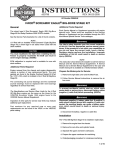
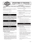
1
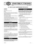
INSTRUCTIONS
REV. 12-23-02
-J02359
®
Kit Numbers 22444-0200, 22445-02, 22446-02, 22447-02, 22447-02, 22448-02, 22449-02, 22450-02,
22451-02 and 22452-02
SCREAMIN’ EAGLE TWIN CAM (HTCC Heads) STROKER FORGED PISTON KIT
General
i05280
These High Compression forged stroker piston kits are designed
for installation on Harley-Davidson Twin Cam motorcycles with
stroker flywheels, HTCC heads and 1550 big bore cylinders
installed.
Kit Number
22444-02
22445-02
22446-02
22447-02
22448-02
22449-02
22450-02
22451-02
22452-02
Description
Forged Piston Kit, Standard (pair)
Forged Piston Kit, + .005 (pair)
Forged Piston Kit, + .010 (pair)
Front, Forged Piston Kit, Standard
Rear, Forged Piston Kit, Standard
Front, Forged Piston Kit, + .005
Rear, Forged Piston Kit, + .005
Front Forged Piston Kit, + .010
Rear, Forged Piston Kit, + .010
NOTE
1550 Kits require separate purchase of two head gaskets (part
number 16787-99). These are available from your Harley
Davidson Dealer.
For optimal performance, exhaust seals should be replaced
with Screamin’ Eagle Exhaust Seals (Part Number 17048-98).
See Service Parts Page a list of kit contents.
1WARNING
The rider’s safety depends on the correct installation of this
kit. If the Service Manual instructions are not within your capabilities or you do not have the correct tools to install this kit,
have your Harley-Davidson dealer perform this installation.
Incorrect installation of this kit could result in death or serious
injury.
CAUTION
This engine related performance part is intended for High
Performance or Racing applications and is not legal for sale or
use on pollution controlled motor vehicles. This kit will reduce
or void the limited vehicle warranty. Engine related performance parts are intended for the experienced rider only.
Figure 1. Kit Contents (Kit Part Number 22444-02 Shown)
1WARNING
To protect against shock and accidental start-up of vehicle,
disconnect the negative battery cable before proceeding.
Inadequate safety precautions could result in death or serious
injury.
1WARNING
Always disconnect the negative battery cable first. If the positive battery cable should contact ground with the negative
cable installed, the resulting sparks may cause a battery
explosion which could result in death or serious personal
injury.
SERVICE MANUAL REQUIRED
This Instruction Sheet refers to the applicable Service Manual for
many procedures; therefore, Harley-Davidson recommends that
you do not attempt to install this kit without having a copy of the
Service Manual covering your model available. Service Manuals
are available from your Harley-Davidson dealer.
1WARNING
To avoid death or serious injury, do not smoke or allow open
flame or sparks anywhere in the area when working on fuel
system components. Gasoline is extremely flammable and
highly explosive under certain conditions.
1 of 3
Installation Notes
1.
i03105
Disassembly - Follow the procedures in the ENGINE section
of the Service Manual to remove cylinder heads, cylinders
and pistons.
2.
Inspection Of Parts - Follow the procedures in the ENGINE
section of the Service Manual for Inspection of Parts.
3.
Boring And Honing - Follow the procedures in the ENGINE
section of the Service Manual for Boring and Honing
instructions.
4.
Circlip
Notch in Piston
Assembly - Follow the procedures in the ENGINE section of
the Service Manual to install cylinder heads, cylinders and
pistons.
NOTES
• Install rings with dots or bevels facing up. Rings with no
markings can be installed either side up.
Figure 2.
i03106
Thumb Orientation
• 1550 Cylinders do not use O-rings (part number 11273) on
the top cylinder dowels. Therefore, do not install them when
using torque plates or at final assembly of engine.
• Re-jetting, and/or re-timing of engine, may be required to
realize full potential of this performance product.
• All dimensions listed are given in inches. Piston dimensions
to be measured .38 inches above lowest part of skirt.
• Always follow the break-in procedure outlined in the
appropriate owner’s manual after rebuilding an engine.
Specifications
PISTONS
Fit in cylinder
.0025-0035
Compression ring gap
Top
Second
.009-.015
.019-.029
Oil control rail gap
.010-.030
Service Wear Limits
PISTONS
Fit in cylinder
.005
Compression ring gap
Top
Second
.025
.039
Oil control rail gap
.030
-J02359
Circlip 85% Seated
Figure 3.
NOTE
To install Piston Pin Circlips, use the following procedure.
NOTE
Piston in photo not Included in kit. Shown for Circlip
installation purposes only.
1. See Figure 2. Insert open end of circlip into notched
section of piston.
2. See Figure 3. Using thumb oriented as shown, press
firmly until approximately 85% of circlip is seated.
3. Being careful not to scratch or mar piston, use a small
bladed screwdriver to wedge circlip into remainder of
groove. Repeat for remaining circlips.
2 of 3
®
Kit Nos. 22444-02 and others
Service Parts
Date 12/02
S.E. Twin Cam Stroker Piston Kit
i03104
2A, 2B
2
4
3
1
4
Item
1
2
2A
-J02359
Description
Piston
Ring set
Standard (2)
+.005 (2)
+.010 (2)
Front Piston and Ring Set Kits
Piston and ring set (Standard)
Piston and ring set (+.005)
Piston and ring set (+.010)
Part Number
not sold
Item
2B
22457-03
22458-03
22459-03
22447-02
22448-02
22451-02
3
4
Description
Rear Piston and Ring Set Kits
Piston and ring set (Standard)
Piston and ring set (+.005)
Piston and ring set (+.010)
Part Number
22448-02
22450-02
22452-02
Piston pin (2)
Piston pin circlip (4)
22455-03
22456-03
3 of 3