1
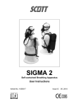
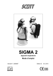
SIGMA 2
Self-contained Breathing Apparatus
User Instructions
Article No. 1035017
Issue F
12. 2004
Self-contained Breathing Apparatus
Contents
WARNINGS................................................................................................................................................................................ii
1.
INTRODUCTION........................................................................................................................................................1
1.1
IMPORTANT ..............................................................................................................................................1
1.2
BREATHABLE AIR.....................................................................................................................................1
1.3
APPARATUS DURATION ..........................................................................................................................1
1.4
PERSONNEL TRAINING ...........................................................................................................................1
1.5
SERVICING................................................................................................................................................2
1.6
SPARE PARTS AND ACCESSORIES .......................................................................................................2
1.7
NOTIFIED BODIES ....................................................................................................................................2
2.
TECHNICAL DESCRIPTION .....................................................................................................................................2
2.1
GENERAL ..................................................................................................................................................2
2.2
APPARATUS DESCRIPTION ....................................................................................................................2
2.3
PNEUMATIC SYSTEM...............................................................................................................................4
2.4
REDUCER..................................................................................................................................................4
2.5
DEMAND VALVE .......................................................................................................................................4
2.6
FACEMASKS .............................................................................................................................................5
3.
PRE-USE AND MONTHLY CHECKS........................................................................................................................6
3.1
GENERAL ..................................................................................................................................................6
3.2
PNEUMATICS............................................................................................................................................6
3.3
DEMAND VALVE .......................................................................................................................................6
3.4
CHECK FACEMASK ..................................................................................................................................6
3.5
POSITIVE PRESSURE, BYPASS AND LEAK TEST .................................................................................7
3.6
WHISTLE TEST .........................................................................................................................................7
3.7
REPLACING CYLINDERS .........................................................................................................................7
3.7.1
Fitting a replacement Cylinder of the same size........................................................................8
3.7.2
Fitting a replacement Cylinder of a different size. .....................................................................8
4.
DONNING PROCEDURE ..........................................................................................................................................8
4.1
HARNESS ..................................................................................................................................................8
4.2
DON FACEMASK.......................................................................................................................................8
4.2.1
Head Harness............................................................................................................................8
4.2.2
Headnet .....................................................................................................................................9
4.3
OPEN CYLINDER VALVE..........................................................................................................................9
4.4
FACEMASK SEAL CHECK ...................................................................................................................... 10
4.5
BYPASS CHECK...................................................................................................................................... 10
4.6
LEAK TEST .............................................................................................................................................. 10
4.7
WHISTLE TEST ....................................................................................................................................... 10
4.8
CYLINDER PRESSURE........................................................................................................................... 11
5.
DOFFING INSTRUCTIONS ..................................................................................................................................... 11
5.1
REMOVE FACEMASK ............................................................................................................................. 11
5.2
TURN OFF CYLINDER ............................................................................................................................ 12
5.3
REMOVE APPARATUS ........................................................................................................................... 12
5.4
CLEAN AND CHECK APPARATUS......................................................................................................... 12
6.
AFTER USE............................................................................................................................................................. 12
6.1
CLEAN FACEMASK................................................................................................................................. 12
6.2
CLEAN APPARATUS............................................................................................................................... 13
6.3
DEMAND VALVE ..................................................................................................................................... 13
6.4
CHECK APPARATUS .............................................................................................................................. 13
6.5
FIT FULLY CHARGED CYLINDER.......................................................................................................... 13
6.6
LEAK TEST .............................................................................................................................................. 13
6.7
RECORD TEST DETAILS........................................................................................................................ 14
6.8
STORAGE................................................................................................................................................ 14
7.
SCHEDULED MAINTENANCE................................................................................................................................ 14
7.1
MONTHLY................................................................................................................................................ 14
7.2
ANNUALLY .............................................................................................................................................. 14
DECLARATION OF CONFORMITY - MARINE EQUIPMENT DIRECTIVE ............................................................................. 15
Registered Office: Scott Health and Safety Limited, Pimbo Road, West Pimbo,
Skelmersdale, Lancashire, WN8 9RA, United Kingdom.
i
WARNINGS
Please Read Carefully and Fully Understand
This manual is for use by personnel trained in the use and care of compressed air
breathing apparatus, and MUST NOT be used as a self-teaching guide by untrained users.
Failure to understand or adhere to the SIGMA 2 User Instructions may result in injury or
death.
Scott Health and Safety Limited have taken great care to ensure that the information in
this manual is accurate, complete and clear. However, Training & Technical Support
Services will be pleased to clarify any points in the manual and answer questions on
SCOTT breathing apparatus.
The following warnings are in accordance with certifying authority requirements and
apply to the use of breathing apparatus in general:
Breathing apparatus users must be fully trained in the use and care of selfcontained, compressed air breathing apparatus.
Ensure that the selection of the apparatus type is sufficient for the tasks
being undertaken and the hazards likely to be encountered. Please refer to
National Regulations for guidance.
In order to ensure the optimum performance and user safety, the apparatus
must be tested and serviced in accordance with Section 7 and the notes in
Section 1 under Personnel Training and Servicing.
The quality of air used to supply and charge breathing apparatus must meet
the requirements of EN 132 : 1990. See Section 1 for details.
The wearing of beards, side-burns or spectacles may adversely affect the
sealing of a facemask to the wearer's face.
The apparatus is not designed for use underwater.
The harness must not be used as a vehicle seat restraint.
DISCLAIMER
Failure to follow these instructions or misuse of the apparatus may result in: death,
injury or material damage; and invalidate any warranty or insurance claims.
COPYRIGHT
This manual must not be copied in part or in whole, or used for purposes other than it’s
intended purpose without the written permission of Scott Health and Safety Limited.
ii
SIGMA 2
The mineral oil content shall be such that
the air is without the odour of oil. The odour
threshold is in the region of 0.3 mg/m3.
1. INTRODUCTION
1.1
IMPORTANT
The water content shall not exceed 50
mg/m3 for 207 bar apparatus and 30 mg/m3
for 300 bar apparatus.
SIGMA 2 must be serviced in accordance
with the Servicing Schedule on at least an
annual basis. Please refer to notes under
Servicing.
1.3
These instructions for the use, care and
maintenance of the apparatus must be
followed to ensure the correct and safe
operation of SIGMA 2.
For any enquiries regarding the use of
SCOTT breathing apparatus, please
contact Training & Technical Support
Services at Scott Health and Safety
Limited.
1.2
1.
Workload: high work rates increase
consumption rates.
2.
Weight of apparatus and use of
heavy or restrictive clothing.
3.
Work environments with extremes of
heat or cold.
4.
Physical fitness of the wearer.
5.
Other factors include emotional
stress and fatigue.
It is important that all wearers are aware of
these factors and take account of them
when assessing cylinder duration.
BREATHABLE AIR
Air used to supply or charge breathing
apparatus may be natural or synthetic. The
composition of breathable air is given in
Table 1.
COMPONENT
MASS %
(Dry Air)
VOLUME%
(Dry Air)
OXYGEN
23.14
20.948
NITROGEN
75.52
78.08
ARGON
1.29
0.93
CARBON
DIOXIDE
0.05
0.031 4
HYDROGEN
0.000 003
0.000 05
NEON
0.001 270
0.001 818
HELIUM
0.000 037
0.000 524
KRYPTON
0.000 330
0.000 114
XENON
0.000 039
0.000 009
APPARATUS DURATION
All durations quoted are nominal, based on
an Average Wearer Consumption Rate of
40 litres/minute and FULLY CHARGED
cylinders. Actual Wearer Consumption
rates vary due to many factors, such as:
1.4
PERSONNEL TRAINING
Personnel
who
use
self-contained,
compressed air breathing apparatus must
be fully trained in accordance with these
instructions and national regulations.
These instructions cannot replace an
accredited training course run by fully
qualified instructors in the proper and safe
use of SCOTT breathing apparatus.
Please contact Training & Technical
Support Services or your distributor for
training course details.
Table 1: Breathable Air
There is an increased fire risk when the
oxygen content is above the value shown.
Training & Technical Support Services:
Scott Health and Safety Limited
Pimbo Road, West Pimbo,
Skelmersdale, Lancashire,
WN8 9RA, United Kingdom.
The purity/quality of air used to supply and
charge breathing apparatus should be
tested periodically in accordance with
national regulations. If not specified
otherwise, contaminants shall not exceed
the permissible exposure level.
Tel: +44 (0) 1695 711711
Fax: +44 (0) 1695 711775
National regulations must be observed.
1
SIGMA 2
1.5
2. TECHNICAL
DESCRIPTION
SERVICING
SIGMA 2 must be serviced at scheduled
intervals by personnel who have completed
a formal training course and hold a current
certificate for servicing and repairing
SCOTT breathing apparatus. Details of the
servicing schedule are contained in the
SCOTT SIGMA 2 Service Manual, copies
of which can only be obtained by registered
holders of a current certificate.
2.1
Your distributor or Training & Technical
Support Services can provide training
course details and quotes for service
contracts. Please see above for contact
details.
1.6
SIGMA 2 is approved for use at sea by:
Lloyds Inspectorate, in accordance with
SOLAS regulation 17 and the 1980
Merchant Shipping Act.
Marine Equipment Directive, certified on
the basis of a BSI examination to the
requirements
of
Council
Directive
96/98/EC, as amended by 98/85/EC.
SPARE PARTS AND
ACCESSORIES
Our Customer Services Department
provide an efficient, friendly, customer
contact point for ordering new apparatus,
spare parts and accessories. The team can
also provide general information on SCOTT
products.
Please call Scott Health and Safety
Limited for further apparatus approval
details.
2.2
Customer Services:
APPARATUS
DESCRIPTION
SIGMA 2 has a lightweight backplate and
harness. The two stage pneumatic system
consists of a first stage reducing valve; and
a Demand Valve (DV) that is attached by a
bayonet fitting, to the positive pressure full
facemask.
Scott Health and Safety Limited
Pimbo Road, West Pimbo,
Skelmersdale, Lancashire,
WN8 9RA, United Kingdom.
Tel: +44 (0) 1695 711711
Fax: +44 (0) 1695 711775
1.7
GENERAL
SIGMA 2 is a self-contained, open circuit,
compressed
air,
positive
pressure,
breathing apparatus, approved to EN 137
(self-contained open circuit breathing
apparatus). It is '
CE'marked in accordance
with Council Directive 89/686/EEC.
The backplate is injection moulded
polyamide/glass/carbon composite, with a
fully adjustable flame retardant polyester
webbing harness. The Kevlar cylinder
band is fully adjustable and can
accommodate one cylinder from the range
listed in Table 2. A glass-filled polyamide
cam-lock buckle facilitates quick and easy
cylinder replacement. A lumbar pad,
fabricated from flame retardant polyester
and packed with flame retardant closed cell
foam, cushions the weight of the apparatus.
It is attached to the lower backplate by
means of press-studs. Pneumatic hoses
run in channels moulded into the inner
backplate. Hose retaining clips are
moulded on the edge of the channels. A
cylinder valve retainer on the lower
backplate provides a secure mounting for
the cylinder valve.
NOTIFIED BODIES
Inspec International Ltd (No. 0194)
Upper Wingbury Courtyard,
Wingrave, Aylesbury,
Buckinghamshire,
HP22 4LW,
United Kingdom.
British Standards Institute (No. 0086)
389 Chiswick High Road,
London,
W4 4AL,
United Kingdom.
2
SIGMA 2
Cylinder Types
Water
Volume
(litres)
Charging
Pressure
Free Air
Volume
(litres)
Nominal
Duration
(minutes)
Warning
Period
(minutes)
Total
Duration
(minutes)
Cylinder
Charged
Weight
(Kg)
CYL-1200
6.0
207
1200
22
8
30
8.8
CYL-HWG-1200
6.0
207
1200
22
8
30
7.2
CYL-FWC-1300
4.7
300
1300
25
7
32
5.0
CYL-1640
6.0
300
1640
33
8
41
12.5
10.0
CYL-HWG-1640
6.0
300
1640
33
8
41
CYL-FWC-1640
6.0
300
1640
33
8
41
6.3
CYL-1800
9.0
207
1800
33
12
45
13.0
CYL-HWG-1800
9.0
207
1800
33
12
45
11.2
CYL-FWC-1800
9.0
207
1800
33
12
45
6.75
CYL-FWC-1860
6.8
300
1860
37
9
46
6.75
CYL-2240
11.0
207
2240
41
15
56
14.4
CYL-FWC-2460
9.0
300
2460
50
12
62
8.8
Table 2: Cylinders approved for use with SIGMA 2
Cylinder Material is identified by codes within the Cylinder Type. Table 3 identifies the
meaning of the cylinder material code and the specification to which the cylinder is
manufactured:
Code
Material
Specification
No Code
Steel (e.g.: CYL-1200)
BS5045 Pt.1
HWG
Hoop Wrapped Glass Fibre (e.g.: CYL-HWG-1200)
HSE-AL-HW1
FWC
Fully Wrapped Carbon (e.g.: CYL-FWC-1300)
HSE-AL-FW2
Table 3: Cylinder Codes and Specifications
Durations are nominal and based on an Average Wearer Consumption Rate of 40 L/min and
are for fully charged cylinders.
Total Duration =
Nominal Duration =
Warning Period =
Cylinder Free Air Capacity
Average Wearer Consumption Rate
Total Duration minus the Warning Period.
Cylinder Water Capacity x Whistle Operating Pressure
Average Wearer Consumption Rate
3
SIGMA 2
2.3
PNEUMATIC SYSTEM
2.5
The first stage pressure reducer has an
integral cylinder connector handwheel.
There is a sintered bronze particle filter in
the reducer inlet.
DEMAND VALVE
SIGMA 2 is available with two types of
Demand Valve (DV):
•
Instant air positive pressure DV (blue)
•
First breath-activated DV (black).
A high pressure PTCFE lined hose supplies
air to a shoulder mounted pressure gauge
and warning whistle.
Both types of DV have a supplementary
flow bypass and operate in conjunction with
the spring-loaded facemask exhalation
valve to maintain a positive pressure within
the facemask.
The pressure gauge has a stainless steel
case and a polycarbonate, impact resistant,
splinter-proof lens. A blow-out vent
prevents over pressurisation of the case. A
rubber
shroud
provides
mechanical
protection.
The DV senses the changes in facemask
air pressure that occur when the wearer
breathes; and uses this to regulate the
supply of air to the facemask. The DV is
attached to the facemask by a quick-fit
bayonet connection with a spring loaded
locking catch.
The warning whistle operates at 55 bar.
Table 2 details the Warning Period for each
apparatus and cylinder combination.
If the hose, whistle or gauge become
damaged, a restrictor in the reducer body
limits air loss to 25 litres/minute.
2.4
REDUCER
Instant Air Demand Valve
The instant air DV supplies air to the
facemask when the cylinder valve is
opened.
The pressure reducer is a simple spring
and piston device that reduces the
pressure of air from the cylinder to a
medium pressure of between 5 and 9 bar.
The operation is automatic and selfregulating such that the reducer requires no
adjustment.
In the unlikely event of a malfunction in the
reducer, resulting in an uncontrolled rise in
the output pressure, a pressure relief valve
protects the medium pressure system.
A reinforced hose supplies
pressure air to the DV.
First Breath Demand Valve
medium
4
SIGMA 2
The first breath version can be shut by
pressing a reset button on the DV and
opens when the wearer takes the first
breath. This permits the DV to be removed
from the facepiece while the cylinder valve
is open, without loss of cylinder air.
PanaSeal is suitable for medium and
smaller face sizes. PanaVisor is suitable
for medium to larger face sizes. Vision 3 is
available in three sizes: small, medium and
medium/large.
The bypass provides a constant flow of air
in the unlikely event that the regulator
malfunctions in a ‘no flow’ mode.
The bypass is opened by turning the knob
through 90°. As use of the bypass
consumes cylinder air rapidly, it must only
be used to escape from the hazardous
area.
2.6
FACEMASKS
SIGMA 2 is approved for use with: Vision
3,
PanaSeal
and
PanaVisor
full
facemasks, all of which conform to EN 136.
All are available with 5-point, fully
adjustable web or net head harnesses and
neckstraps. An inner mask minimises CO2
dead space and visor misting. A speech
diaphragm is fitted.
PanaSeal/PanaVisor Facemask with
Headnet
Vision 3 is moulded in grey silicone, while
PanaSeal and PanaVisor are nondermatitic black neoprene, or blue silicone.
Vision 3 Facemask with Headharness
5
SIGMA 2
3. PRE-USE AND
MONTHLY CHECKS
3.1
3.3
DEMAND VALVE
1.
Check that the DV O-ring is clean
and undamaged.
GENERAL
2.
Fit the DV to the facemask and check
that the locking catch clicks into place.
Gently twist the DV to ensure that it is
securely fitted.
1.
Check that all parts are clean and
undamaged.
2.
Ensure that the shoulder harness is
fully slackened and that a fully charged
cylinder is securely attached to the
backplate. Replace discharged cylinders.
3.
Check that the harness slides freely
through buckles.
4.
Check that the facemask visor is
clear and free from marks and damage that
might impair vision. Fully slacken
headharness straps.
5.
Apparatus that fails any of these
checks must be serviced in accordance
with the SIGMA 2 Service Manual.
3.2
3.
Check that the bypass valve is closed
(flat area on knob is toward the facepiece).
PNEUMATICS
4.
On first breath DVs only, press the
black reset button.
3.4
1.
Check cylinder connector O-ring is
clean and undamaged.
1.
CHECK FACEMASK
Don the facemask (see Section 4.2).
2.
Open the cylinder valve and check
that the cylinder is full.
2.
Screw handwheel connector firmly
into the cylinder valve outlet.
3.
Check
that
the
facemask
pressurises. If necessary adjust the mask
to obtain a leak tight fit. DO NOT overtighten the harness as this distorts the
mask.
3.
Check that pressure gauge, whistle
and hoses are in good condition and are
not kinked or stretched.
6
SIGMA 2
3.5
POSITIVE PRESSURE,
BYPASS AND LEAK TEST
3.6
WHISTLE TEST
1.
With the cylinder valve still closed,
monitor the pressure gauge and breathe
down air in the system. Check that the
whistle sounds clearly at between 50 and
60 bar.
1.
Insert fingers in the facemask seal
and check there is a steady flow of air out
of the mask.
2.
Remove fingers and allow mask to
re-seal.
2.
Release headharness and remove
the facemask.
3.
Apparatus that passes all of these
checks is now ready for use.
3.7
REPLACING CYLINDERS
3.
Open the bypass and check there is
a steady flow of air into the facemask.
4.
Close the bypass.
5.
Close the cylinder valve, hold your
breath, and monitor the pressure gauge for
10 seconds. Check that the reading does
not drop during this period.
1.
Check that the cylinder valve is
closed and slowly undo the cylinder
connector handwheel. Remove the reducer
from the cylinder.
7
SIGMA 2
2.
Grasp the sides of the cam-lock
buckle with the index finger and thumb of
the right hand, use the left index finger to
slide back the ribbed catch and lift the
buckle.
4. DONNING
PROCEDURE
4.1
HARNESS
3.
Open the buckle and lift the empty
cylinder from the backplate.
3.7.1
Fitting a replacement
Cylinder of the same size.
1.
Fit the cylinder valve through the
cylinder valve retainer, connect the buckle
hinge and close the cam-lock.
3.7.2
Fitting a replacement
Cylinder of a different size.
1.
Don apparatus. Adjust shoulder
straps for a comfortable fit, then fasten
waistbelt and adjust for a snug fit.
4.2
DON FACEMASK
1.
Check that the bypass is shut (and
on first breath DVs, press the DV reset
button).
1.
Adjust the length of the cylinder band
to permit the buckle hinge to be connected.
4.2.1
2.
Adjust the cylinder band length until
the cylinder band grips the cylinder firmly,
then close the cam-lock.
Head Harness
3.
Tidy the free end of the cylinder band
into the loops.
1.
Let facemask hang loosely from face
and breathe normally.
8
SIGMA 2
3.
Tighten the side straps for a firm,
comfortable fit. DO NOT over-tighten as
this distorts the face seal.
2.
Fit the chin into the chin-cup, pull the
harness over the top of the head and
tighten the straps in sequence: bottom,
middle, top. DO NOT over-tighten.
4.2.2
4.3
OPEN CYLINDER VALVE
Headnet
1.
1.
With the headnet straps fully
extended, insert the chin into the chin-cup
and use the loop at the back of the headnet
to pull the headnet over the head.
2.
Tighten the top strap to bring the
visor and ori-nasal mask to the correct
level.
9
Slowly open cylinder valve fully:
• On Instant Air DVs, check that
the DV free-flows into facemask
until the headharness straps are
tightened.
• On First Breath DVs, inhale
sharply to start the air supply to
the facemask.
SIGMA 2
4.4
FACEMASK SEAL CHECK
4.6
1.
Take a breath and hold it. Release
handwheel locking-mechanism and close
the cylinder valve.
1.
Insert fingers in facemask seal and
check for a steady flow of air from the
mask. Remove fingers and allow mask to
re-seal.
4.5
LEAK TEST
2.
Listen for leaks and monitor gauge
for 10 seconds. The reading on the gauge
should not fall during this period.
BYPASS CHECK
4.7
WHISTLE TEST
1.
Open the bypass and check there is
a steady flow of air into the facemask.
2.
Close the bypass.
1.
Slowly breathe down the air from the
system and check that the whistle sounds
clearly at between 50 and 60 bar.
2.
If the whistle or facemask fail the
test, return the apparatus for servicing, with
an
explanatory
note
attached,
in
accordance with the SIGMA 2 Servicing
Instructions.
10
SIGMA 2
4.8
5. DOFFING
INSTRUCTIONS
CYLINDER PRESSURE
1.
Open cylinder valve and check
pressure gauge to ensure that cylinder has
a minimum of 80% of the fully charged
capacity:
For 207 bar cylinders - 170 bar.
For 300 bar cylinders - 240 bar.
5.1
REMOVE FACEMASK
2.
When fully satisfied with apparatus,
proceed to undertake tasks as required.
1.
On apparatus with a First Breath DV,
take a breath and press the reset button to
close the air supply.
2.
Pull tabs on buckles forward to
release the headharness or headnet.
Remove facemask.
Note:
Instant Air DVs will free flow
through mask until the cylinder valve is
closed.
11
SIGMA 2
5.2
6. AFTER USE
TURN OFF CYLINDER
CAUTIONS:
•
•
•
6.1
1.
Disengage
the
cylinder
valve
handwheel locking mechanism and turn
handwheel fully clockwise to shut the valve.
5.3
DO NOT immerse DV or warning
whistle in water. A yellow cap is
provided to protect the DV outlet.
ALWAYS use the recommended
cleaning methods.
The apparatus MUST be thoroughly
dried prior to storage. Pay
particular attention to the valve
flaps.
CLEAN FACEMASK
REMOVE APPARATUS
1.
Withdraw red locking catch, turn 90°
clockwise and remove the DV from the
facemask.
2.
Wash and disinfect the mask
thoroughly in a solution of TriGeneTM and
warm water. See following Note.
1.
Release the waistbelt, slacken the
shoulder straps and remove the apparatus.
3.
Rinse the mask thoroughly in clean
running water. Pay particular attention to
flushing out the exhale valve.
2.
Open cylinder band, undo cylinder
valve connector and remove cylinder.
3.
Mark cylinder as ‘empty’ and return
for charging.
4.
Hang mask by its neckstrap and
allow it to dry thoroughly away from direct
heat or sunlight.
5.4
5.
When dry, wipe facemask seals with
TriGeneTM disinfectant wipes.
CLEAN AND CHECK
APPARATUS
6.
Polish the visor inside and out with a
clean, lint-free cloth and slacken the head
harness, ready for use.
1.
The apparatus must be cleaned and
tested in accordance with the instructions
given in Section 6 - After Use, prior to being
returned to service.
12
SIGMA 2
Note:
TriGeneTM Cleansing and Disinfecting
Solution is available from Scott Health and
Safety Limited in 1 litre and 5 litre
containers under Article Numbers 2008247
and 2008248 respectively.
Pump dispensers are available for the
above under Article Numbers 1017672 (1
litre) and 1017670 (5 litres).
TriGeneTM Disinfecting Wipes are available
from Scott Health and Safety Limited in
packs of 20 sachets under Article Number
2004225.
6.2
5.
Operate the red locking catch a
number of times. Ensure that it moves
freely and does not stick.
CLEAN APPARATUS
CAUTION: DO NOT use abrasive or
solvent cleaners.
6.4
1.
Fully slacken the shoulder straps and
waistbelt. Clean off any dirt with a stiff
brush or sponge with warm water and soap,
followed by a thorough rinse.
2.
Check hoses for signs of abrasion or
damage.
2.
Ensure that the pressure gauge face
is clean.
6.3
CHECK APPARATUS
1.
Check apparatus thoroughly for signs
of wear or damage.
3.
Check harness straps and stitching
for signs of weakness.
DEMAND VALVE
4.
Replace
worn
or
damaged
components in accordance with the SIGMA
2 Service Manual.
5.
If a fault is found, attach an
explanatory note to the apparatus and
return it for servicing.
6.5
FIT FULLY CHARGED
CYLINDER
1.
Fit a fully charged cylinder in
accordance with the instructions contained
within Section 3 - Pre-Use and Monthly
Checks.
6.6
1.
Fit the protective yellow cap over the
DV outlet and use a small stiff brush with a
mild soap and water solution to clean
around the catch.
LEAK TEST
CAUTION:
On Instant Positive Pressure DVs (blue),
DO NOT fit the yellow cap prior to
opening the cylinder valve as this will
damage the DV.
2.
If the catch does not move freely,
return the apparatus for servicing.
3.
Check that the orange O-ring on the
DV outlet is clean and in good condition.
1.
Open cylinder valve. The DV will free
flow. Fit yellow protective cap over the DV
outlet, airflow will cease.
4.
Replace O-ring if in less than perfect
condition.
2.
Check pressure gauge to ensure that
the cylinder is full.
13
SIGMA 2
3.
Close cylinder valve and monitor the
pressure gauge for one minute. Check that
the pressure does not drop by more than
10 bar (one gauge division) in this time.
7. SCHEDULED
MAINTENANCE
7.1
4.
If apparatus fails this test it must be
withdrawn from service and returned for
servicing.
5.
Gently lift the yellow DV cap and
allow air to vent from system. Check
pressure gauge and ensure that the
warning whistle sounds clearly between 50
and 60 bar.
6.7
Details of such checks should be recorded
within the appropriate register and a copy
kept for future inspection. Please see
Section 6.7 for details.
RECORD TEST DETAILS
7.2
Record test details in accordance with local
regulations in a breathing apparatus
logbook (available from Scott Health and
Safety Limited under Article Number
1034745).
Information recorded usually includes:
•
•
•
•
•
6.8
MONTHLY
The apparatus should be examined and
tested at least once a month in accordance
with the instructions given in this manual
under Check Apparatus.
ANNUALLY
The apparatus must be tested and
components replaced in accordance with
the SIGMA 2 Service Schedule, contained
within the SIGMA 2 Service Manual. Please
refer to notes under Personnel Training and
Servicing at the beginning of this manual
for further details.
Name and address of employer
responsible for the apparatus.
Make, model number or mark of the
apparatus, together with a description
of
any
distinguishing
features,
sufficient to enable clear identification.
The date of the examination together
with the name, signature or unique
authentication mark of the examiner.
The condition of the apparatus and
details of any defects found and any
remedial action taken.
Cylinder air pressure.
.
STORAGE
The apparatus must be stored in a clean,
dry environment away from direct heat and
sunlight.
Storage temperature should not exceed
+40°C to -10°C.
14
SIGMA 2
DECLARATION OF CONFORMITY
MARINE EQUIPMENT DIRECTIVE
Scott Health and Safety Limited
Pimbo Road, West Pimbo,
Skelmersdale, Lancashire,
WN8 9RA, United Kingdom.
declares that the following Personal Protective Equipment
‘SIGMA 2 Self-contained Compressed Air Breathing Apparatus’
•
Is in conformity with the provisions of Council Directive 96/98 EC on Marine
Equipment. Type-Examination Certificate BSI/A.1/3.7/051 issued by BSI Product
Services (Notified Body No 0086) relates.
•
Is in conformity with the provisions of Council Directive 89/686/EEC relating to
Personal Protective Equipment when assessed against Harmonised Standard BS
EN137. Type-Examination Certificate No 505 issued by Inspec International Ltd
(Notified Body No 0194) relates.
•
Is manufactured under a Quality Control System which has been satisfactorily
assessed against the requirements of Article 11, Section B of Council Directive
89/686/EEC; 96/98 EC MED MODULE D and Production Quality Assurance
Module D (Notified Body No 0086).
Robert Sutton
Project Leader,
Scott Health and Safety Limited.
17th October 2002
15
Scott Health and Safety Limited
Pimbo Road, West Pimbo,
Skelmersdale, Lancashire,
WN8 9RA, United Kingdom.
Tel: +44 (0) 1695 711711
Fax: +44 (0) 1695 711775