1
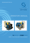
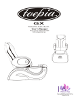
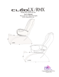
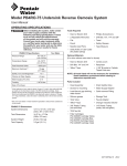
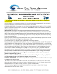
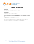
AUTOTROL® 363 DEMAND AUTOMATIC FILTER VALVE
Service Manual
©2014 Pentair Residential Filtration, LLC
www.pentairaqua.com/pro
TABLE OF CONTENTS
MANUAL OVERVIEW................................................................. 2
SAFETY INFORMATION............................................................. 2
TYPICAL TOOLS AND FITTINGS REQUIRED............................. 3
VALVE DIMENSIONS................................................................. 3
VALVE LAYOUT.......................................................................... 4
SPECIFICATIONS...................................................................... 4
EQUIPMENT INSTALLATION..................................................... 4
SYSTEM STARTUP..................................................................... 6
INSTALLATION CHECKLIST...................................................... 6
CONTROL OPERATION AND LAYOUT....................................... 6
PROGRAMMING THE 606F DEMAND CONTROL...................... 7
REMOTE REGENERATION........................................................ 8
VALVE ASSEMBLY..................................................................... 9
TROUBLESHOOTING................................................................. 10
FLOW DIAGRAMS...................................................................... 11
FLOW PERFORMANCE DATA CHARTS..................................... 12
Mechanical
MANUAL OVERVIEW
General
How To Use This Manual
This manual is designed to guide the installer through the
process of installing and starting the filter.
This manual is a reference and will not include every system
installation situation. The person installing this equipment
should have:
• Knowledge in water filter installation
• Basic plumbing skills
Icons That Appear In This Manual
WARNING: Failure to follow this instruction can result in
personal injury or damage to the equipment.
NOTE: This will make the process easier if followed.
Inspection
Inspect the unit for damage or missing parts.
SAFETY INFORMATION
Electrical
• There are no user-serviceable parts in the AC adapter,
motor, or controller. In the event of a failure, these should
be replaced.
• All electrical connections must be completed according to
local codes.
• Use only the power AC adapter that is supplied.
• The power outlet must be grounded and always on.
• To disconnect power, unplug the AC adapter from its
power source.
• Install an appropriate grounding strap across the inlet
and outlet piping of the water system to ensure proper
grounding is maintained.
2 • Autotrol® 363 Demand Automatic Filter Valve
• Do not use petroleum-based lubricants such as
petroleum jelly, oils, or hydrocarbon-based lubricants.
Use only 100% silicone lubricants.
• All plastic connections should be hand tightened.
Plumber tape should be used on connections that do not
use an O-ring seal. Do not use pliers or pipe wrenches.
• All plumbing must be completed according to local codes.
• Soldering of the plumbing should be done before
connecting to the valve. Excessive heat will cause interior
damage to the valve.
• Observe local drain line requirements.
• Do not use lead-based solder for sweat solder
connections.
• Do not support the weight of the system on the control
valve fittings, plumbing, or the bypass.
• It is not recommended to use sealants on the threads.
Use plumber tape (PTFE) on all threads.
• Observe all warnings that appear in this manual.
• This system is not intended to be used for treating water
that is microbiologically unsafe or of unknown quality
without adequate disinfection before or after the system.
• Keep the unit in the upright position. Do not turn on side,
upside down, or drop. Turning the tank upside down will
cause media to enter the valve.
• Operating ambient temperature is between 34°F (1°C)
and 120°F (49°C).
• Operating water temperature is between 34°F (1°C) and
100°F (38°C).
• Working water pressure range is 20 to 125 psi
(1.38 to 8.61 bar).
• Follow state and local codes for water testing.
• When filling media tank, do not open water valve
completely. Fill tank slowly to prevent media from exiting
the tank.
• Always make modifications to house plumbing first.
Connect to valve last.
• Plastic parts and O-rings may be damaged by heat and
solvents. When constructing plumbing connections, allow
heated parts to cool and protect parts from solvents.
Location Selection
Location of a water treatment system is important. The
following conditions are required:
• Level platform or floor.
• Constant electrical supply to operate the controller.
• Total minimum pipe run to water heater of ten feet (three
meters) to prevent backup of hot water into system.
• Local drain or tub for discharge as close as possible.
• Water line connections with shutoff or bypass valves.
• Room to access equipment for maintenance.
SAFETY INFORMATION continued
Outdoor Locations
It is recommended that the equipment be installed indoors.
When the water conditioning system must be installed
outdoors, several items must be considered.
• Moisture — The valve and controller are rated for NEMA 3
locations. Falling water should not affect performance.
The system is not designed to withstand extreme humidity
or water spray from below. Examples are: constant heavy
mist, near corrosive environment, upwards spray from
sprinkler.
• Direct Sunlight — The materials used will fade or discolor
over time in direct sunlight. The integrity of the materials
will not degrade to cause system failures.
• Temperature — Extreme hot or cold temperatures may
cause damage to the valve or controller.
Freezing temperatures will freeze the water in the valve.
This will cause physical damage to the internal parts as
well as the plumbing.
• Insects — The controller and valve have been designed to
keep all but the smallest insects out of the critical areas.
VALVE DIMENSIONS
9.83” (249.57 mm)
7.75” (196.94 mm)
3.60” (91.56 mm)
5.18”(131.47 mm)
TYPICAL TOOLS AND FITTINGS REQUIRED
•
•
•
•
•
•
•
•
•
•
•
•
Pipe Cutter
Tubing Cutter
File
Pliers
Tape Measure
Soldering Tools
Lead Free Solder
Bucket
Towel
Plumber Tape
Adjustable Wrench
Tube 100% Silicone Grease
4.22” (107.21 mm) 5.61” (142.37 mm)
4.00” (101.60 mm)
.75” (19.03 mm)
Figure 1
Autotrol® 363 Demand Automatic Filter Valve • 3
VALVE LAYOUT
EQUIPMENT INSTALLATION
Inlet
Outlet
If you are also installing a water softener, the softener should
be installed downstream of this system.
Grounding the Plumbing
It is important that the plumbing system be electrically
grounded. When a water treatment system is installed a
nonmetallic bypass valve may interrupt the grounding. To
maintain continuity, a grounding strap can be purchased at a
hardware store. When it is installed the strap will connect the
plumbing into the system to the plumbing leaving the system.
Drain
Display
Recycle
Button
Time
Button
Backwash
Duration
Button
Water Line and Bypass Connection
Once you have selected your location check the direction of the
water flow in the main pipe.
A bypass valve system should be installed on all water
conditioning systems. The bypass valve system isolates the
filter from the water supply and provides untreated water to
service during routine maintenance and servicing procedures.
B
Cleaning Cycle
Interval/Days
Button
Delayed
Cleaning Cycle
Indicator
Flow
Indicator
Remove
Cover
Figure 2
SPECIFICATIONS
Flow Rates (Valve Only)
Service @ 15 psi.....................................21 gpm (79 lpm) full flow
Backwash @ 25 psi.................................19 gpm (72 lpm) full flow
Fast Rinse @ 25 psi................................................5 gpm (19 lpm)
Valve Connections
Tank Thread..............................2-1/2 inches (63.5 mm) – 8, male
Inlet/Outlet Thread...................... 3/4 inch (19.05 mm) BSP, male
..................................................... 3/4 inch (19.05 mm) NPT, male
...........................................................1 inch (22.5 mm) BSP, male
.......................................................... 1 inch (22.5 mm) NPT, male
..................................................1-1/4 inch (31.75 mm) BSP, male
..................................................1-1/4 inch (31.75 mm) NPT, male
....................................................1-1/2 inch (38.1 mm) BSP, male
....................................................1-1/2 inch (38.1 mm) NPT, male
2
1
3
Figure 3
Normal Operation
• Valves 1 and 3 open
• Valve 2 closed
Bypassed Position
• Valve 2 open
• Valves 1 and 3 closed
The valve connects to the water system by means of a
connector assembly. The connector is secured to the plumbing
and then inserted into the universal ports on the valve. A clip is
used to hold it in place.
Drain Line..........................................1 inch (22.5 mm) BSP, male
.......................................................... 1 inch (22.5 mm) NPT, male
Distributor Tube Diameter............................. 1.050 inch (27 mm)
Distributor Tube Length.... Flush to top of tank ± 1/2 inch (13 mm)
Design Specifications
Valve Body........................................................Glass-filled Noryl®
Rubber Components......................... Compounded for cold water
Operating Pressure.............................. 20-125 psi (1.38–8.61 bar)
Water Temperature...........................................34-100°F (1-38°C)
Ambient Temperature*.....................................34-120°F (1-49°C)
* Recommended for indoor use only
Drain Line Flow Controls
1" (22.5 mm) ............................................... 8-20 gpm (30-76 lpm) .
3/4" (1.9 cm) .................................................4-7 gpm (15-29 lpm)
4 • Autotrol® 363 Demand Automatic Filter Valve
Figure 4 Connector Assembly
Before inserting the connector:
• Check that all O-rings are in place and not damaged.
• O-rings are pre-lubricated. Sliding surfaces should be
lubricated with 100% silicone grease.
EQUIPMENT INSTALLATION continued
Firmly insert connector into the valve body. Press locking clip
into position. Make certain the clip is fully engaged.
To remove a clip:
1. Turn off water and release water pressure at the valve.
2. Push the water line connectors into the valve body. This will
help release O-rings that may have seated in place.
3. Remove the clip by inserting a flat blade under the top
center of the clip and lifting (prying up) (Figure 4 Connector
Assembly).
WARNING: Do not use pliers to remove a clip. It is likely
the clip will break.
Drain Line Flow Control
The drain line flow control (DLFC) requires assembly
(Figures 4 and 5).
1 Inch Drain Line Flow Control
Rates 8 - 20 GPM
Drain Line Connection
NOTE: Standard commercial practices are expressed here.
Local codes may require changes to the following
suggestions. Check with local authorities before
installing a system.
4. Use appropriate fittings to connect tubing to the DLFC
connection on valve.
5. The drain line may be elevated up to 6 feet (1.8 m) providing
the run does not exceed 15 feet (4.6 m) and water pressure
at the filter is not less than 40 psi (2.76 bar). Elevation can
increase by 2 feet (61 cm) for each additional 10 psi (.69 bar)
of water pressure at the drain connector.
6. Where the drain line is elevated but empties into a drain
below the level of the control valve, form a 7 inch (18 cm)
loop at the far end of the line so that the bottom of the loop
is level with the drain line connection. This will provide an
adequate siphon trap.
7. Secure the discharge end of the drain line to prevent it from
moving.
Right Way
Install washer with printed
lettering facing the valve body.
4002493 Rev A
Figure 5 - 1" Drain Line Flow Control
3/4 Inch Drain Line Flow Control
Rates 4 - 7 GPM
Figure 7 Drain Line Connection
NOTE: Waste connections or drain outlet shall be designed
and constructed to provide for connection to the
sanitary waste system through an air gap of two
pipe diameters or one inch (22 mm), whichever is
larger.
WARNING: Never insert drain line directly into a drain,
sewer line, or trap (Figure 7 Drain Line
Connection). Always allow an air gap between
the drain line and the wastewater to prevent
the possibility of sewage being back-siphoned
into the filter.
Electrical Connection
Install washer with printed
lettering facing the valve body.
4002492 Rev A
Figure 6 - 3/4" Drain Line Flow Control
Note: Install DLFC washer with printed lettering facing the
valve body.
WARNING: This valve and control are for dry location use
only unless used with a Listed Class 2 power
supply suitable for outdoor use.
The 363 controller operates on 12-volt alternating current
power supply. This requires use of the an AC adapter with your
system.
Make sure power source matches the rating printed on the AC
adapter.
Autotrol® 363 Demand Automatic Filter Valve • 5
SYSTEM STARTUP
CONTROL OPERATION AND LAYOUT
The system will now need to be placed into operation. Please
review Manually Initiating A Cleaning Cycle on page
7 before attempting startup.
Large LED Display
A large two digit LED readout is highly visible in most
installation settings.
1. With the supply water for the system still turned off,
position the bypass valve to the “not in bypass” (normal
operation) position.
2. Press and hold the button on the controller for three
seconds. This will initiate a manual cleaning cycle, and
cycle the valve to the backwash position.
3. Filling the media tank with water:
A. With the system in backwash, open the water supply
valve very slowly to approximately the 1/4 open position.
Water will begin to enter the media tank. Air will begin
to be purged to drain as the media tank fills with water.
WARNING: If opened too rapidly or too far, media may
be lost out of the tank into the valve or the
plumbing. In the 1/4 open position, you should
hear air slowly escaping from the valve drain
line.
B. When all of the air has been purged from the media
tank (water begins to flow steadily from the drain line),
open the main supply valve all of the way. This will purge
any remaining air from the tank.
C. Allow water to run to drain until the water runs clear
from the drain line. This purges any debris from the
media bed.
D. Turn off the water supply and let the system stand for
about five minutes to allow any trapped air to escape
from the media tank. Turn on the water supply after five
minutes. Check for leaks.
The system is now fully operational.
INSTALLATION CHECKLIST
___ Read the owner's/installation manual?
___ Follow all safety guidelines in the manual?
___ If metal pipe was used, did you restore the electrical ground?
___ Securely install drain hose to an approved drain?
___ Perform a leak test?
___ Move the bypass valve to service?
___ Start a cleaning cycle?
6 • Autotrol® 363 Demand Automatic Filter Valve
Simplified Three-Step Programming
Only three buttons are required to fully program the control.
Recycle Button
Initiates either a delayed or immediate cleaning cycle.
Time Button
Displays or programs the time of day.
Cleaning Cycle Interval Button
Displays or programs the amount of water to treat between
cleaning cycles.
Backwash Duration Button
Displays or programs the amount of time to elapse during the
backwash cycle step.
Flow Indicator
The decimal point/flow indicator blinks on and off when water
flow turns the meter.
Power Loss Memory Retention
The control features battery-free time of day retention during
loss of power. The time will remain in memory.
Note: All other programmed parameters are stored in the
flash memory and are retained during power outages.
Display
Recycle
Button
Time
Button
Backwash
Duration
Button
Cleaning Cycle
Interval/Days
Button
Delayed
Cleaning Cycle
Indicator
Flow
Indicator
Figure 8
Remove
Cover
PROGRAMMING THE 606F DEMAND
CONTROL
Time of Day: Press to display the current time value in
hours. The time value is displayed as a number from 0 to 23,
with 0 representing midnight and 23 representing 11:00 PM.
While the value is being displayed, press the button to increase
the value. Press and hold the button to rapidly advance the
value. Release the button when the desired value is displayed.
The value will be stored in memory after five seconds.
Range: 0 - 23 hours
Note: The elapsed minutes will reset to zero when the hours
are changed.
Backwash Duration: Press to display the current backwash
cycle step duration setting. The value in minutes will be
displayed for five seconds. While the value is being displayed,
press the button to increase the value. Press and hold the
button to rapidly advance the value. Press and hold the button
to rapidly advance the value. Release the button when the
desired value is displayed. The value will be stored in memory
after five seconds.
Range: 2 - 50 minutes
NOTE: The Rapid Rinse cycle step adjusts automatically
based on the Backwash Duration value. See table
below.
Backwash Time
Rinse Time
2 - 5 minutes
1 minute
6 - 9 minutes
2 minutes
10 - 13 minutes
3 minutes
14 - 17 minutes
4 minutes
18 - 21 minutes
5 minutes
22 - 25 minutes
6 minutes
26 - 29 minutes
7 minutes
30 - 35 minutes
8 minutes
36 - 40 minutes
9 minutes
41 - 50 minutes
10 minutes
Cleaning Cycle Interval: Press to display the current
cleaning cycle interval setting. The value in cubic meters
(metric units) or hundreds of gallons (U.S. units) to treat
between cleaning cycles will be displayed for five seconds.
While the value is being displayed, press the button to increase
the value. Press and hold the button to rapidly advance the
value. Press and hold the button to rapidly advance the value.
Release the button when the desired value is displayed. The
value will be stored in memory after five seconds.
Range: .4 - 9.5 cubic meters
100 - 4,000 gallons
Default: 1.0 cubic meters
10 x100 (1,000) gallons
Calendar Override: To set a time duration between cleaning
cycles to ensure proper function of the filter in the event of a
flow sensor malfunction, press and hold and for three
seconds. The value in days between cleaning cycles will be
displayed for five seconds. While the value is being displayed,
press the button to increase the value. Press and hold the
button to rapidly advance the value. Release the button when
the desired value is displayed. The value will be stored in
memory after five seconds.
Range: 8 hours (0.3 days) - 30 days; 0 to disable
Default: 0 (disabled)
Accessing History Values
The control features a review level that displays the operation
history of the system. This is a great troubleshooting tool for
the control valve.
To access history values, press and simultaneously and
hold for three seconds to view the diagnostic codes.
NOTE: If a button is not pushed for 30 seconds the controller
will exit the history values table.
Press to advance through the table. When the desired
diagnostic code is reached, Press to display the value.
Some history values may have up to four digits. Press to
display the first two digits of the value. Press to display the
last two digits.
Code
Description
H1
Days since last cleaning cycle
H2
Current day of week
(displayed as 0 - 6)
H3
Water used today since 1:00 AM
H4
Water used since last cleaning cycle
A0
Average water usage for day 0
A1
Average water usage for day 1
A2
Average water usage for day 2
A3
Average water usage for day 3
A4
Average water usage for day 4
A5
Average water usage for day 5
A6
Average water usage for day 6
Manually Initiating A Cleaning Cycle
Delayed Cleaning Cycle
Press and release to program a delayed cleaning cycle. The
system will regenerate at the next cleaning cycle time
(1:00 AM). Repeat procedure to disable the scheduled cleaning
cycle. The display indicator dot blinks when a delayed cleaning
cycle is scheduled.
Immediate Cleaning Cycle
Press and hold the for three seconds to initiate an
immediate cleaning cycle. The control cycles to the backwash
cycle step. The control will proceed through a complete
cleaning cycle. A cascading symbol (- -) will be displayed until
the cycle is complete.
Autotrol® 363 Demand Automatic Filter Valve • 7
PROGRAMMING THE 606F DEMAND
CONTROL continued
Quick Cycling The Control
Quick Cycling
Press and hold for three seconds to initiate an immediate
cleaning cycle. The control will cycle to the backwash cycle
step.
1. Press and release
to display "C1" (backwash).
2. Simultaneously press then release and to move the
control to the next cycle step, "C2" (rinse).
NOTE: The time may be displayed for 5 seconds.
3. During a cycle step, press and release
"- -" and "C#".
to toggle between
4. Repeat steps 2 and 3 to cycle through each position.
Quick Cycle to Service Position
Simultaneously press and and hold for three seconds
during any cleaning cycle step. The control will skip the
remaining cycle steps and return to the service position. The
time of day will be displayed when the control reaches the
service position.
AUXILIARY SWITCH
An optional auxiliary switch kit (P/N 4002757) is available for
the 363 demand valve to control an auxiliary switch when a
cleaning cycle is initiated.
8 • Autotrol® 363 Demand Automatic Filter Valve
VALVE ASSEMBLY
12
14
15
11
10
16
8
4
1
9
2
17
3
7
5
6
13
4002436 Rev A
Item No.
QTY
Part No.
Description
1��������������������1����������4002555������������������Kit, Valve Discs, 360 Series Filter
2��������������������1����������4002211������������������Top Plate, 360 Series Filter
3�������������������14���������1234170������������������Screw, Pan Head, #8-18 x 9-16 LG
4��������������������1����������4002213������������������Spring, One Piece
5��������������������1����������4002212������������������Cam, 3 Cycle, 360 Series Filter
6��������������������1����������1000589������������������Cap, Pillow Block
7��������������������1�������������������������������������������Control Assemblies
�������� 4002658�������������Control Assembly, 363/606F,
North American
�������� 4002659�������������Control Assembly, 363/606F,
World
8��������������������1����������4001260������������������12 Volt Motor Assembly w/ Optical
Sensor
9��������������������1����������4001889������������������Valve O-ring Kit
10������������������1����������3022576������������������Transformer Cable
11������������������1�������������������������������������������AC Wall Mount Adapters
�����������1000811������������������North American Wall Trans - 115VAC
�����������1000812������������������Australian Wall Trans - 240V
�����������1000813������������������British Wall Trans - 240 V
�����������1262524������������������Europe Cord Connect Trans - 240V
�����������1000814������������������Europe Wall Trans - 240V
�����������1000810������������������Japan Wall Trans - 100V
12������������������1�������������������������������������������Drain Line Flow Control
�������� 4002459�������������Kit, DLFC, 4.0GPM, NPT, 360, Fltr
�������� 4002460�������������Kit, DLFC, 4.5GPM, NPT, 360, Fltr
�������� 4002461�������������Kit, DLFC, 5.0GPM, NPT, 360, Fltr
�������� 4002462�������������Kit, DLFC, 6.0GPM, NPT, 360, Fltr
�������� 4002463�������������Kit, DLFC, 7.0GPM, NPT, 360, Fltr
�������� 4002464�������������Kit, DLFC, 8.0GPM, NPT, 360, Fltr
�������� 4002465�������������Kit, DLFC, 9.0GPM, NPT, 360, Fltr
�������� 4002466�������������Kit, DLFC, 10GPM, NPT, 360, Fltr
�������� 4002467�������������Kit, DLFC, 12GPM, NPT, 360, Fltr
�������� 4002468�������������Kit, DLFC, 15GPM, NPT, 360, Fltr
Item No.
QTY
Part No.
Description
�������� 4002469�������������Kit, DLFC, 20GPM, NPT, 360, Fltr
�������� 4002476�������������Kit, DLFC, 4.0GPM, BSP, 360, Fltr
�������� 4002477�������������Kit, DLFC, 4.5GPM, BSP, 360, Fltr
�������� 4002478�������������Kit, DLFC, 5.0GPM, BSP, 360, Fltr
�������� 4002479�������������Kit, DLFC, 6.0GPM, BSP, 360, Fltr
�������� 4002480�������������Kit, DLFC, 7.0GPM, BSP, 360, Fltr
�������� 4002481�������������Kit, DLFC, 8.0GPM, BSP, 360, Fltr
�������� 4002482�������������Kit, DLFC, 9.0GPM, BSP, 360, Fltr
�������� 4002483�������������Kit, DLFC, 10GPM, BSP, 360, Fltr
�������� 4002484�������������Kit, DLFC, 12GPM, BSP, 360, Fltr
�������� 4002485�������������Kit, DLFC, 15GPM, BSP, 360, Fltr
�������� 4002486�������������Kit, DLFC, 20GPM, BSP, 360, Fltr
13������������������1����������4002757������������������Kit, Auxiliary Switch, 363 Filter
14���������������1�������� 1033444�������������Meter Assembly
15���������������1�������� 3027837�������������Meter Cable
16���������������2�������� 40576�����������������Clip, H, Plastic, 7000
17���������������2�����������������������������������Kit, Connector (includes one
connector and one O-ring)
�����������42414-11����������������Connector, 3/4" BSP, Plastic
�����������42414-01����������������Connector, 3/4" NPT, Plastic
�����������61626����������������������Connector, 3/4" & 1" Sweat
�����������61561-10����������������Connector, 1" BSP, Brass
�����������40563-11����������������Connector, 1" BSP, Plastic
�����������61561����������������������Connector, 1" NPT, Brass
�����������40563-01����������������Connector, 1" NPT, Plastic
�����������40565-11����������������Connector, 1-1/4" BSP, Plastic
�����������40565-01����������������Connector, 1-1/4" NPT, Plastic
�����������61562-10����������������Connector, 1-1/2" BSP, Brass
�����������42241-11����������������Connector, 1-1/2" BSP, Plastic
�����������61562����������������������Connector, 1-1/2" NPT, Brass
�����������42241-01����������������Connector, 1-1/2" NPT, Plastic
�����������41242-01����������������Connector, 1" & 1-1/4", Sweat
�����������41243-01����������������Connector, 1-1/4" & 1-1/2" Sweat
Autotrol® 363 Demand Automatic Filter Valve • 9
TROUBLESHOOTING
Control Error Codes
Problem
Possible Cause
Solution
E1 is displayed.
Program settings have been corrupted.
Press any key. Reprogram control. If E1 does not clear,
replace control.
E3 is displayed.
Control does not detect the camshaft position and is
returning to the service position.
Wait until the control returns to the service position.
Camshaft is not turning during E3 display.
Check that motor is connected. Verify that the motor wire
harness is connected to motor and controller module. Verify
that optical sensor is connected and in place. Verify that
motor gear has engaged the camshaft.
If everything is connected, replace components in this order:
1. Motor Assembly, Optical Sensor
2. Control
Camshaft is turning more than five minutes to find Home
position:
Verify that optical sensor is in place and connected to wire.
Inspect for debris in the camshaft slots.
If motor continues to rotate indefinitely, replace the following
components in this order:
1. Motor Assembly, Optical Sensor
2. Control
System
Problem
Flowing or dripping water at drain after
cleaning cycle.
Control will not complete a cleaning cycle
automatically.
Possible Cause
Solution
Debris is preventing #3 or #4 valve disc from
closing.
Remove debris.
Worn #3 or #4 valve disc.
Replace valve discs.
AC adapter or motor not connected.
Connect power.
Debris is preventing camshaft from rotating.
Remove debris.
Defective motor.
Replace motor.
Meter clogged with debris.
Remove and clean meter.
Backwashes or purges at excessively low or
high rate.
No drain line flow control.
Install drain line flow control.
Restricted drain line.
Remove restriction.
Flow indicator on control does not display
service flow.
Bypass system in bypass position.
Remove bypass system from bypass.
Meter cable dislodged from valve.
Fully insert meter cable into valve.
Meter clogged with debris.
Remove and clean meter.
10 • Autotrol® 363 Demand Automatic Filter Valve
FLOW DIAGRAMS
SERVICE
BACKWASH
Untreated Water
Untreated Water
Treated Water
Backwash
Inlet
Inlet
1
2
1
2
Outlet
Outlet
4
3
4
Drain
Control
Drain
Control
Drain
Valve No.
Valve No.
1. Closed
1. Open
2. Open
2. Closed
3. Closed
3. Open
4. Closed
4. Closed
3
Drain
Media Tank
Media Tank
FAST RINSE
Untreated Water
Rinse
Inlet
1
2
Outlet
4
3
Drain
Control
Drain
Valve No.
1. Closed
2. Open
3. Closed
4. Open
Media Tank
Autotrol® 363 Demand Automatic Filter Valve • 11
FLOW PERFORMANCE DATA CHARTS
Service
Cv = 5.43
30
PRESSURE DROP IN PSI
25
20
15
10
5
0
1
6
11
16
21
26
FLOW IN GPM
BW
Cv = 3.74
35
PRESSURE DROP IN PSI
30
25
20
15
10
5
0
1
6
11
FLOW IN GPM
12 • Autotrol® 363 Demand Automatic Filter Valve
16
21
For Autotrol® Product Warranties visit:
Autotrol para las garantías de los productos visite:
Pour Autotrol® garanties produit visitez le site :
®
}
www.pentairaqua.com/pro
FILTRATION & PROCESS
5730 NORTH GLEN PARK ROAD, MILWAUKEE, WI 53209
P: 262.238.4400 | www.pentairaqua.com | 800.279.9404 | F: 262.518.4404 | [email protected]
All Pentair trademarks and logos are owned by Pentair, Inc. All other brand or product names are trademarks or registered marks of their respective owners.
Because we are continuously improving our products and services, Pentair reserves the right to change specifications without prior notice.
Pentair is an equal opportunity employer.
4002752 Rev A FE14 ©2014 Pentair Residential Filtration, LLC All Rights Reserved.