1
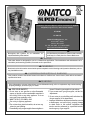
Installation, Operation Manual, and Service Manual for Super‐E SP (Spark) High‐Efficiency Water Heater Models: SE‐199‐80 SE‐199‐119 National Combustion Co., Inc. 104‐11 180th Street Jamaica, NY 11433 Ph: 718‐291‐8400 Fx: 718‐291‐6870 www.nationalcombustion.com
Recognize this symbol as an indication of
important Safety Information!
Do Not Destroy this Manual. Please read carefully
and keep in a safe place for Future Reference.
NOTICE
This water heater is designed for use in a commercial application. The installation and maintenance of it
should be performed by qualified, licensed service personnel.
WARNING
Read and review this entire manual with special emphasis on the Venting and Operation Sections prior to
any installation work.
CALIFORNIA PROPOSITION 65 WARNING
This product contains chemicals known to the State of California to cause cancer, birth defects and other
reproductive harm.
WARNING
If the information in these instructions are not followed exactly, a fire or explosion may result causing
property damage, personal injury or death.
FOR YOUR SAFETY!
phone. Follow the gas supplier’s instructions.
• If you cannot reach your gas supplier, call the fire
department.
• Do not return to your building until authorized by
the gas supplier or fire department.
— Improper installation, adjustment, alteration, service
or maintenance can cause injury, property damage
or death. Refer to this manual. Installation and
service must be performed by a qualified installer,
service agency or gas supplier.
— Do not store or use gasoline or other flammable
vapors or liquids or other combustible materials in
the vicinity of this or any other appliance. To do so
may result in an explosion or fire
— WHAT TO DO IF YOU SMELL GAS
• Do not try to light any appliance.
• Do not touch any electrical switch; do not use any
phone in your building.
• Immediately call your gas supplier from a neighbor’s
Printed in the USA
1
AP15135
(5/09)
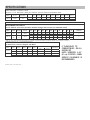
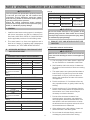
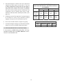
SPECIFICATIONS
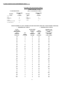
RECOVERY CAPACITIES
Recovery in U.S. Gallons/Hr. (GPH) and Liters/Hr. (LPH) at Various Temperature Rises
MODEL
NUMBER
INPUT (BTU/HR)
NAT. & LP
THERMAL
EFFICIENCY
SE199-80
SE199-119
199,000
95%
UNITS
40°F
(22.2°C)
50°F
(27.8°C)
60°F
(33.3°C)
70°F
(38.9°C)
80°F
(44.4°C)
90°F
(50.0°C)
100°F
(55.6°C)
110°F
(61.1°C)
120°F
(66.7°C)
GPH
573
458
382
327
286
255
229
208
191
LPH
2169
1735
1446
1239
1084
964
867
789
723
Recovery rating is based on thermal efficiencies obtained in Intertek testing laboratory.
All models exceed the minimum energy efficiency requirements of current ASHRAE 90.1 requirements.
MAXIMUM DELIVERY
In U.S. Gallons and Liters (Includes useable storage and recovery for indicated times)
MODEL
NUMBER
GALLONS/
MAX
SETPOINT
LITERS
INPUT (BTU/HR)
NAT. & LP
SE199-80
80
303
160º
71ºC
199,000
SE199-119
119
450
160º
71ºC
199,000
TEMP.
RISE
UNITS
5
MIN.
10
MIN.
15
MIN.
20
MIN.
30
MIN.
45
MIN.
1
HR.
2
HR.
3
HR.
100°F
GAL.
75
94
113
132
171
228
285
514
743
37.7°C
LTR.
284
357
429
501
646
863
1079
1947
2814
100°F
GAL.
102
121
141
160
198
255
312
542
771
37.7°C
LTR.
338
460
532
604
749
966
1183
2050
2918
MIN. TO RECOVER
CONTENTS
21
31
All models have a maximum setpoint of 160°F with the exception of the HE55-160 and HE55-199 booster models. The HE55-160 and HE55-199 have a maximum setpoint of 180°F.
* NOTE: The 180º F models are shipped with all necessary components for an approved installation (see Booster Installation Kit for component list on Page 7.)
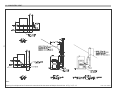
DIMENSIONAL INFORMATION
All dimensions shown in English and Metric
MODEL
NUMBER
HE80-199
HE119-199
UNITS
VENT
APPROX
SHIPPING WT.
WIDTH
inches
72
23 1/2
32
3*
1-1/2
1-1/2
mm
1854
597
813
76
38
38
106 kgs
inches
73
27
36
3*
1-1/2
1-1/2
405 lbs.
mm
1854
686
914
76
38
38
184 kgs
All models require a 120V power source.
DEPTH
WATER CONNECTIONS
INLET
OUTLET
HEIGHT
235 lbs.
0" CLEARANCE TO
COMBUSTIBLES ON ALL
SUPER-E SP
UNITS, HOWEVER, A 24"
(61 cm) CONTROL PANEL
SERVICE CLEARANCE IS
RECOMMENDED.
TABLE OF CONTENTS ______________________
Part 1: General Safety Precautions ___________________________________4-5
Part 2: Installation _______________________________________________6-10
Local Installation Regulations ____________________________________ 6
Location _____________________________________________________ 6
Temperature and Pressure Relief Valve ____________________________ 6
Expansion Tank _______________________________________________ 6
Potable Water Connections ______________________________________ 7
Lighting and Operating Instructions ________________________________ 8
Electrical Connection ___________________________________________ 9
Gas Connection _____________________________________________9-10
Part 3: Venting, Combustion Air & Condensate Removal ________________11-17
General ____________________________________________________ 11
Approved Materials for Exhaust Vent and Intake Air __________________ 11
Exhaust Vent and Intake Air Vent Pipe Locations _________________ 11-13
Exhaust Vent and Intake Air Vent Sizing ___________________________ 14
Longer Vent Runs ____________________________________________ 14
Exhaust Vent and Intake Air Pipe Installation ____________________ 14-15
VeryImportant Set-up Instructions ________________________________ 15
Concentric Vent ______________________________________________ 16
Vent Length Maximum Reference Chart ___________________________ 17
Part 4 : Operation ______________________________________________18-20
Overall Appliance and Control Operation __________________________ 18
Status Mode _________________________________________________ 18
Test Mode _______________________________________________ 18-19
Operating Instructions _________________________________________ 20
Shutdown Procedure __________________________________________ 20
Prevent Combustion Air Contamination____________________________ 20
Corrosive Contaminants and Source Products to Avoid _______________ 21
Condensate _________________________________________________ 21
Part 5 : Components and Wiring ___________________________________22-23
Components Diagram _________________________________________ 22
Wiring Diagram ______________________________________________ 23
Part 6 : Troubleshooting _________________________________________24-25
Part 7: How to Get Your Super-E Serviced _____________________________ 26
Part 8: Standard Piping Diagrams ___________________________________ 27
1 Unit, Standard ______________________________________________ 27
2 Units without Recirculator _____________________________________ 28
2 Units with Recirculator _______________________________________ 29
Part 9: Warranty _________________________________________________ 30
3
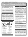
PART 1: GENERAL SAFETY PRECAUTIONS
Be sure to read and understand the entire Use & Care Manual before attempting to install or operate this water heater.
Pay particular attention to the following General Safety Precautions. Failure to follow these warnings could result in a fire
or explosion, causing property damage, bodily injury or death. Should you have any problems understanding the instructions in this manual, STOP, and get help from a qualified installer or service technician or the gas supplier.
WARNING
DANGER
Gasoline, as well as other flammable materials and
liquids (adhesives, solvents, etc.), and the vapors
they produce, are extremely dangerous. DO NOT
handle, use or store gasoline or other flammable
or combustible materials anywhere near or in the
vicinity of a water heater. Be sure to read and follow
the warning label pictured below and other labels on
the water heater, as well as the warnings printed in
this manual. Failure to do so can result in property
damage, bodily injury, or death.
LIQUEFIED PETROLEUM MODELS
-Propane, or LP gas, must be used with great caution.
· It is heavier than air and will collect first in lower
areas making it hard to detect at nose level.
· Make sure to look and smell for LP leaks before
attempting to light appliance. Use a soapy solution
to check all gas fittings and connections. Bubbling at
a connection indicates a leak that must be corrected.
When smelling to detect an LP leak, be sure to sniff
near the floor.
· Gas detectors are recommended in LP applications
and their installation should be in accordance with
the manufacturer’s recommendations and/or local
laws, rules, regulations or customs.
· It is recommended that more than one method be
used to detect leaks in LP applications.
IF LP GAS IS PRESENT OR SUSPECTED:
· DO NOT attempt to find the cause yourself;
· DO NOT try to light any appliance;
· DO NOT touch any electrical switch;
· DO NOT use any phone in your building.
· Leave the house immediately and make sure your
family and pets leave also.
· Leave the doors open for ventilation and contact
the gas supplier, a qualified service agency or the
fire department.
· Keep the area clear until the service call has been
made, the leak is corrected, and a qualified agency
has determined the area to be safe.
DANGER
Failure to install and properly vent the water heater
to the outdoors as outlined in the Venting Section
of this manual can result in unsafe operation of the
water heater. To avoid the risk of fire, explosion, or
asphyxiation from carbon monoxide, never operate
this water heater unless it is properly vented and has
an adequate air supply for proper operation. Be sure
to inspect the vent system for proper installation at
initial start-up and at least annually thereafter. Refer
to maintenance section of this manual for more
information regarding vent system inspections.
DANGER
WARNING
FLAMMABLES
Both LP and natural gas have an odorant added to
help detection. Some people may not physically be
able to smell or recognize this odorant. If unsure
or unfamiliar about the smell associated with LP or
natural gas, ask the gas supplier. Other conditions,
such as “Odorant Fade”, which causes the odorant
to “fade”, or diminish in intensity can also hide or
camouflage a gas leak.
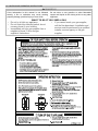
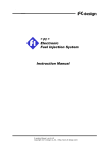
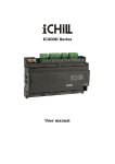
Flammable Vapors
Vapors from flammable
liquids will explode and
catch fire causing death or
severe burns.
Do not use or store flammable
products such as gasoline,
solvents or adhesives in the
same room or area near the
water heater.
Keep flammable products:
1. far away from heater,
2. in approved containers,
3. tightly closed and
4. out of children's reach.
Installation:
Do not install water heater
where flammable products will
be stored or used unless the
main burner and pilot flames
Water heater has a main
burner and pilot flame.
The pilot flame:
1. which can come on at
any time and
2. will ignite flammable
vapors.
Vapors:
1. cannot be seen,
2. are heavier than air,
3. go a long way on the
floor and
4. can be carried from
other rooms to the pilot
flame by air currents.
DANGER
Water heaters utilizing Liquefied Petroleum gas (LP)
are different from natural gas models. A natural gas
heater will not function safely on LP gas and vice
versa. No attempt should ever be made to convert a
heater from natural gas to LP gas. To avoid possible
equipment damage, personal injury or fire: DO
NOT connect this water heater to a fuel type not in
accordance with unit rating plate. Propane gas for
propane units. Natural gas for natural gas units.
These units are not certified for any other type fuel.
are at least 18" above the
floor. This will reduce, but not
eliminate, the risk of vapors
being ignited by the main
burner or pilot flame.
Read and follow water heater warnings and instructions. If owners
manual is missing, contact the retailer or manufacturer.
4
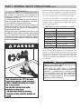
PART 1: GENERAL SAFETY PRECAUTIONS cont’d
WARNING
Maximum water temperatures occur just after burner has
shut off. To find temperature of the water being delivered, turn on a hot water faucet and place a thermometer in the hot water stream and read the thermometer.
LP appliances should not be installed below-grade
(for example, in a basement) if such installation is
prohibited by federal, state and/or local laws, rules,
regulations, or customs.
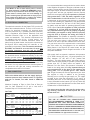
The following chart details the relationship of water temperature and time with regard to scald injury and may be
used as a guide in determining the safest water temperature for your applications.
To meet commercial water use needs, the thermostat on this water heater is adjustable up to 160°F
(71°C). However, water temperatures over
125° F (52°C) can cause severe burns instantly or
death from scalds. This is the preferred starting
point for setting the controls for supplying general purpose hot water.
Safety and energy conservation are factors to be
considered when setting the water temperature
on the thermostat. The most energy efficient
operation will result when the temperature setting
is the lowest that satisfies the needs consistent
with the application.
TIME / TEMPERATURE RELATIONSHIPS IN SCALDS
Temperature
Time to Produce Serious Burn
120°F (49°C)
More than 5 minutes
125°F (52°C)
1½ to 2 minutes
130°F (54°C)
About 30 seconds
135°F (57°C)
About 10 seconds
140°F (60°C)
Less than 5 seconds
145°F (63°C)
Less than 3 seconds
150°F (66°C)
About 1½ seconds
155°F (68°C)
About
1 second
Table
courtesy of Shrines Burn Institute
The temperature of the water in the heater can be regulated by setting the temperature on the electronic thermostat. To comply with safety regulations, the thermostat
was set at its lowest setting before the water heater was
shipped from the factory. See the section titled SET
POINT ADJUSTMENT PROCEDURE to set the electronic thermostat.
DANGER
There is a Hot Water SCALD Potential if the
thermostat is set too high.
NOTE: When this water heater is supplying
general purpose hot water requirements for use by
individuals, a thermostatically controlled mixing
valve for reducing point of use water temperatures
is recommended to reduce the risk of scald injury.
Contact a licensed plumber or the local plumbing
authority for further information.
5
PART 2: INSTALLATION
WARNING
removed. This water heater must not be located near
flammable liquids such as gasoline, adhesives,
solvents, paint thinners, butane, liquefied propane,
etc. as the controls of this appliance could ignite
those vapors, causing an explosion.
Read and review this entire manual with special
emphasis on the Venting Sections and Operation
Sections prior to any installation work.
A. LOCAL INSTALLATION REGULATIONS
C. TEMPERATURE AND PRESSURE RELIEF VALVE
This water heater must be installed in accordance with
these instructions, local codes, utility company requirements, and/or in the absence of local codes, the latest
edition of the National Fuel Gas Code ANSI 223.1 in the
United States or CAN/CSA B149.1 installation code in
Canada.
A new combination temperature and pressure relief valve,
complying with the Standard for Relief Valves and
Automatic Gas Shutoff Devices for Hot Water Supply
Systems, ANSI Z21.22 or Standard CSA 4.4, must be
installed in the opening provided on the water heater at
the time of installation. No valve is to be placed between
the relief valve and the water heater. For circulating tank
installation, the separate storage tank(s) must have
similar protection. The pressure rating of the relief valve
must not exceed the maximum working pressure as
marked on the front of the water heater. The Btu/h rating
of the relief valve must equal or exceed the Btu/h input of
the water heater as noted on its rating plate. Connect the
outlet of the relief valve to a suitable open drain. The
discharge line must pitch downward from the valve to
allow complete draining (by gravity) of the relief valve and
discharge line, and must be no smaller than the outlet of
the relief valve. The end of the discharge line should not
be threaded or concealed and should be protected from
freezing. No valve of any type, restriction or reducer
coupling should be installed in the discharge line. In the
U.S., local codes shall govern the installation of relief
valves. In Canada, use CAN/CSA B149.1.
The water heater must be located or protected so it is
not subject to physical damage, for example, by moving
objects, area flooding, etc.
CAUTION
The water heater should not be located in an area
where leakage of the tank or connections will result in
damage to the area adjacent to it or to lower floors of
the structure. When such areas cannot be avoided, it
is recommended that a suitable catch pan, adequately
drained, be installed under the water heater.
NOTE: Auxiliary catch pan installation MUST conform to the applicable local codes
B. LOCATION
D. EXPANSION TANK
Choose a location for your water heater centralized to
the piping system, along with consideration to vent pipe
length. As the length of vent pipe increases, the firing
rate of the appliance decreases. You must also locate
the Super-E SP where it will not be exposed to below
freezing temperatures. Additionally, you will need to
place the water heater so that the controls, drain, inlet/
outlet, and gas valve are easily accessed. This appliance
must not be installed outdoors, as it is certified as an
indoor appliance, and must be kept vertical and on a
level surface. Also, care must be exercised when
choosing the location of this appliance where leakage
from the relief valve, leakage from related piping, or leakage from the tank or connections, will not result in damage to the surrounding areas or to the lower floors of the
building. A water heater should always be located in
an area with a floor drain or installed in an adequately drained catch pan suitable for water heaters.
Proper clearance must be provided around the
Super-E SP as follows: Sides, bottom, top, and back
are 0" (zero clearance). Front of the appliance needs 24"
(61 cm) service clearance minimum. This front service
may be achieved by a non-rated or combustible door or
access panel; providing the 24" (61 cm) service clearance
is achieved when the door is opened or panel is
A potable hot water expansion tank may be required to
offset the water expansion as the water is heated. In
most city plumbing systems, the water meter has a no
return or back flow device built into the system to prevent
back flowing of water back into city mains. Back flow preventers may be found on all incoming water supplies.
Under these circumstances, you will need a hot water
expansion tank listed for potable water use. The expansion tank should be located on the cold inlet piping close
to the water heater. The expansion tank must be suitable for hot potable water.
WARNING
The manufacturer’s warranty does not cover any
damage or defect caused by installation or attachment or use of any special attachments such as energy saving devices (other than those authorized by the
manufacturer) into, onto, or in conjunction with the
water heater. The use of such unauthorized devices may
shorten the life of the water heater and may endanger
life and property. The manufacturer disclaims any
responsibility for such loss or injury resulting from
the use of such unauthorized devices.
6
E. DOMESTIC WATER CONNECTIONS
The water connections must be installed in accordance with all national and local plumbing codes, or
any prevailing standard. NEVER USE DIELECTRIC
UNIONS OR GALVANIZED STEEL FITTINGS ON
SUPER-E SP CONNECTIONS. The inlet and out- let
connections are 1" on the 55 gallon models and 11/2" on the 80 and 119 gallon models. On the cold inlet,
install a 1" brass tee on the 55 gallon models, or a 1-1/2"
brass tee on the 80 and 119 gallon models. On the run
of the 1" brass tee install, with pipe sealant, compound a
1" brass drain cock or it’s equivalent (not supplied). Into
the branch of the 1" or 1-1/2" brass tee install a copper
male adapter to match with the copper plumbing system.
For convenience, you may install a shut off valve and a
union in the cold inlet piping to ease servicing in the future. If there is a back flow preventer, or any type of a check
valveinthesystem,thenyoumustinstallanaddi- tional tee for
a suitable potable thermal expansion tank. (See section on
Expansion Tank.) In the hot outlet con- nection, (top
left), install a suitable adapter to match the copper
tubing of the plumbing system. A thermal trap or heat
trap loop may be installed here to provide additional
energy savings and prevent thermal siphoning of domestic hot water. If required, a domestic hot water tempering/anti-scald valve should be installed into the hot water
line to prevent the maximum outlet water temperature
from exceeding 125°F (52°C) to prevent scald injury.
7
G. LIGHTING AND OPERATING INSTRUCTIONS
WARNING
If the information in this manual is not followed
exactly, a fire or explosion may result causing
property damage, personal injury or loss of life.
•
•
•
Do not store or use gasoline or other flammable
vapors and liquids in the vicinity of this or any other
appliance.
WHAT TO DO IF YOU SMELL GAS
Do not try to light any appliance.
• If you cannot reach your gas supplier,
Do not touch any electrical switch: do not
call the fire department. Installation and
use any phone in your building.
service must be performed by a qualified
Immediately call your gas supplier from a
installer, service agency or the gas
neighbor’s phone. Follow the gas
supplier’s instructions.
supplier.
8
WARNING
It is recommended that a soapy solution be used to detect
leaks. Bubbles will appear on the pipe to indicate a leak is
present. The gas piping must be sized for the proper flow
and length of pipe, to avoid excessive pressure drop. Both
the gas meter and the gas regulator must be properly
sized for the total gas load. If you experience a pressure
drop greater than 1” WC, the meter, regulator or gas
line is undersized or in need of service. You can attach
a manometer to the incoming gas drip leg, by removing
the cap and installing the manometer. The gas pressure
must remain between 3.5” WC and 14” WC during standby (static) mode and while in operating (dynamic) mode
at full output. If an in-line regulator is used, it must be
a minimum of 10 feet from the Super-E SP. It is
very important that the gas line is properly purged by
the installer, gas supplier or utility. Failure to properly
purge the lines or improper line sizing, will result in
ignition failure. This problem is especially noticeable in
NEW LP installations and also in empty tank situations.
This can also occur when a utility company shuts off
service to an area to provide maintenance to their lines.
The gas valve must not be replaced with a conventional
gas valve under any circumstances. As an additional
safety feature in the Super-E SP water heater, the gas
valve in this appliance has a flanged connection to the
swirl plate and blower.
Tank MUST be full of water before power is turned
on. Heat exchanger coil WILL BE DAMAGED if energized even for a short time while the tank is dry. The
water heater’s warranty does not cover damage or
failure resulting from operation with an empty or partially empty tank. (Reference is made to the limited
warranty for complete terms and conditions)
H. ELECTRICAL CONNECTION
The electrical connection for the Super-E SP is on the left
side of the combustion shroud. There is a 1/2" knock- out
location for electrical connection. All electrical wiring
must be performed by a qualified licensed electrician,
and in accordance with National Electrical Code and
Canadian Electrical Code, or to the applicable local
codes and standards. The electrical requirements are
for standard 120 volts, 60 Hz., 10 amp service. It is
recommended that an electrical disconnect switch be
placed near the water heater, and that the connection to
the Super-E SP be made using 3/8" extra-flex, or 3/8"
greenfield (or equivalent). This unit must be wired with
#14 AWG, and fused for no more than 15 amps. It is
of extreme importance that this unit be properly
grounded and be connected with proper polarity!
Ground the water heater by connecting the green wire in
the electrical access compartment directly to the main
building ground system. It is very important that the
building system ground is inspected by a qualified
electrician prior to making this connection. Once all
connections have been made, the electrical access may
be closed. It is very important that the electrical power is
not turned on until gas and venting connections are
completed and the tank is full of water.
Gas supply shall not exceed a maximum inlet pressure
of 14" water column (350 mm), 1/2 pound pressure (3.4
kPa), between 3.5” WC and 14” WC (natural and
propane). The entire piping system, gas meter, and regulator must be sized properly to prevent a pressure drop
greater than 0.5" of water column as stated in the
National Fuel Gas Code. Gas pressure information is
listed on the rating plate. It is very important that you
are connected only to the type of gas noted on the
rating plate; “LP” or propane gas or “Nat” natural
gas. All gas connections must be approved by the local
gas supplier or utility in addition to the governing
authority prior to turning the gas supply on. The nipple
provided for the inlet gas connection is 1/2", and it is
mandatory that a 3/4" to 1/2" reducing bushing (provided)
is used, threaded into the branch of a 3/4" tee, and a drip
leg fabricated, as per the National Fuel Gas Code and in
Canada refer to CAN/CSA B149.1.
I. GAS CONNECTION
Refer to the below table to size the supply piping to
minimize pressure drop between meter or regulator
and unit. In Canada, use table found in CAN/CSA
B149.1
Maximum Capacity of Pipe in Cubic Feet of Gas per
Hour for Gas Pressures of 0.5 psi or Less and a
Pressure Drop of 0.3 Inch water Column
You must ensure that the entire gas line to the reducing bushing connection at the Super-E SP is no
smaller than 3/4".
Gas Table
(Nominal
Iron Pipe
Size
(inches)
3/4
1801
1 1/4
1 1/2
Internal
Diameter
(inches)
10
.824
278
1.049
520
1.380
1,050
1.610
1,600
(Nominal
Iron Pipe Internal
Size
Diameter
(inches) (inches)
59 3/4
110 1
1 1/4
1 1/2
.824
1.049
1.380
1.610
Length of Pipe (Feet)
20
190
350
730
1,100
30
152
285
590
890
40
130
245
500
760
50
115
215
440
670
60
105
195
400
610
70
96
370
560
}
CAUTION
BTU’S
PER
HOUR
x1,000
THE USE OF FLEXIBLE GAS CONNECTORS IS
NOT RECOMMENDED. HOWEVER, IF USED, IT IS
IMPERATIVE THAT THEY ARE SIZED CORRECTLY.
FLEXIBLE GAS CONNECTORS MUST HAVE A MINIMUM
ID OF 3/4". A MINIMUM 3/4" ID MUST BE MAINTAINED TO
AVOID RESTRICTION OF GAS FLOW! NEVER REDUCE
THE GAS SUPPLY LINE BELOW 3/4"! In Canada, refer
to CAN/CSA B149.1 for approved connections.
Length of Pipe (Feet)
80
90
100
125
150
90
170
350
530
84
160
320
490
79
150
305
460
72
130
275
410
64
120
250
380
175
225
200
55
100
210
350
320
}
BTU’S
PER
HOUR
x1,000
9
Once all the inspections have been performed, the piping
system must be leak tested. If the leak test pressure is
higher than the maximum permissible inlet pressure, you
must isolate the Super-E SP from the gas line before
testing. In order to do this, you must disconnect the
union and cap the inlet gas line. In the event the gas
valve is exposed to a pressure greater than 1/2 PSI, 14"
water column, the gas valve must be replaced.
Failure to follow all precautions could result in fire,
explosion or death! It is recommended that a soapy
solution be used to detect leaks. Bubbles will appear and
indicate a leak is present. The gas piping must be sized
for the proper flow and length of pipe to avoid unacceptable pressure drop. Both the gas meter and the gas regulator must be properly sized for the total gas load. If you
experience a pressure drop greater than 1" W.C., the
meter or regulator or gas line may be undersized or in
need of service. On the inlet side of the gas valve, there
is a 1/8" NPT plug. This plug can be removed to attach a
manometer. You can attach a meter to the incoming gas
drip leg by removing the cap and installing the meter. The
gas pressure must remain between 3.5" and 14" of water
column during stand-by and unit running heat cycle. If
an in-line regulator is used, it must be a minimum of 10 feet
from the Super-E SP. It is very important that the gas
line is properly purged by the installer, gas supplier
or utility. Failure to properly purge the lines
or improper line sizing, will result in ignition failure
of the Super-E SP.
The gas valve is a special
gas valve which has a Pressure Augmented Regulator
feature, as well as negative outlet pressure. This valve
must not be replaced with a conventional valve under any
circumstances. Make sure valve is in the “OFF” position
prior to turning gas supply on. As an additional safety
feature, this valve has a left hand thread on the outlet end,
and a special tamper resistant electrical connector.
WARNING
Never use open flame to test for gas leaks, as
bodily injury or property damage could result.
WARNING
DO NOT exceed input shown on water heater
rating label.
10
PART 3: VENTING, COMBUSTION AIR & CONDENSATE REMOVAL
WARNING
Table 3-4
APPROVED PIPE CEMENT AND PRIMER FOR PLASTIC PIPE
This vent system will operate with a positive pressure
in the flue gas vent pipe. Do not connect vent
connectors serving appliances vented by natural
draft into any portion of mechanical draft systems
operating under positive pressure.
Follow the venting instructions below carefully.
Failure to do so may result in severe personal injury,
death, or substantial property damage.
MATERIAL
STANDARDS FOR INSTALLATION IN:
CEMENT AND PRIMER
UNITED STATES
CANADA
CPVC
ANSI/ASTM F493
PVC
ANSI/ASTM D2564
ULC-S636 approved
primer and adhesive
system, for ULC-S636
pipe and fittings
WARNING
A. GENERAL
1.
Install the water heater venting system in accordance
with these instructions and with the National Fuel
Gas Code, ANSI Z223.1/NFPA 54, CAN/CGA B149.1,
and/or applicable provisions of local building codes.
2.
This water heater is a direct vent appliance and is
listed as a Category IV appliance with Underwriters
Laboratories, Inc. VENT AND INTAKE AIR VENT
Do not use Foam Core Pipe in any portion of the
exhaust piping from this water heater. Use of Foam
Core Pipe may result in severe personal injury, death,
or substantial property damage.
C. EXHAUST VENT AND INTAKE AIR VENT PIPE
LOCATION
1. Determine exhaust vent location:
B. APPROVED MATERIALS FOR EXHAUST VENT
AND INTAKE AIR VENT
WARNING
Both exhaust and intake air vents must exit from the
same side of the building to assure correct appliance
operation.
Table 3-1
APPROVED PLASTIC EXHAUST VENTING MATERIAL
MATERIAL
STANDARDS FOR INSTALLATION IN:
UNITED STATES
CANADA
PVC SCHEDULE 40 / 80
ANSI /ASTM D1785
ULC-S636
PVC -DWV
ANSI /ASTM D2665
ULC-S636
CPVC SCHEDULE 40 / 80
ANSI /ASTM F441
ULC-S636
a. The vent piping for this water heater is approved
for zero clearance to combustible construction.
b. See illustration within this section of clearances
for location of exit terminals of direct-vent venting
systems.
*Note: Cellular Foam Core Pipe
can only be used on INTAKE
piping.
c. This water heater vent system shall terminate at
least 3 feet (0.9 m) above any forced air intake
located within 10 ft (3 m). Note: this does not
apply to the combustion air intake of this directvent appliance.
Table 3-2
APPROVED PLASTIC INTAKE VENTING MATERIAL
MATERIAL
STANDARDS FOR INSTALLATION IN:
d. Provide a minimum of 1 foot distance from any
door, operable window, or gravity intake into any
building.
UNITED STATES AND CANADA
PVC SCHEDULE 40 / 80
ANSI /ASTM D1785
CPVC SCHEDULE 40 / 80
ANSI /ASTM F441
PVC DWV
PVC-CELLULAR FOAM
CORE*
*Note: Cellular Foam Core Pipe
can only be used on INTAKE
piping.
ANSI /ASTM D2665
e. Provide a minimum of 1 foot clearance from the
bottom of the exhaust above the expected snow
accumulation level. Snow removal may be
necessary to maintain clearance.
U.L. LISTED
f. Provide 4 feet horizontal clearance from
electrical meters, gas meters, gas regulators,
relief equipment, exhaust fans and inlets. In no
case shall the exit terminal be above or below
the aforementioned equipment unless the 4 foot
horizontal distance is maintained.
Table 3-3
APPROVED PLASTIC CONDENSATE PIPING MATERIAL
MATERIAL
STANDARDS FOR INSTALLATION IN:
UNITED STATES AND CANADA
PVC SCHEDULE 40 / 80
g. When adjacent to a public walkway, locate exit
terminal at least 7 feet above grade.
ANSI /ASTM D1785
11
h. Do not locate the exhaust directly under roof
overhangs to prevent icicles from forming.
i.
Provide 4 feet clearance from the inside corner
of vertical walls, chimneys, etc., as well as
horizontal corners created by roof overhangs.
c. When venting with a two pipe system, maximum
distance between intake air vent and exhaust
vent is 6 feet (1.8 m). Minimum distance between
exhaust vent and intake air vent on single water
heater is 8” (0.2 m) center-to-center. Minimum
distance between exhaust vents and intake air
vents on multiple water heaters is 8” (0.2 m)
center-to-center.
2. Determine air intake vent location.
a. Provide 1 foot clearance from the bottom of the
intake air vent and the level of maximum snow
accumulation. Snow removal may be necessary
to maintain clearances.
d. You must place support brackets on vent piping.
The first bracket must be within 1 foot of the
appliance and the balance at 4 foot intervals on
the vent pipe.
b. Do not locate intake air vent in a parking area
where machinery may damage the pipe.
12
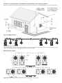
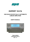
Location of exit terminals of mechanical draft and direct-vent venting systems.
(Reference: National Fuel Gas Code ANSI Z223.1/NFPA 54 2002). In Canada, refer to CAN/CSA B149.1 for vent terminal location
Fig. 3-1 Multiple Vents
Fig. 3-2 Multiple Vent Spacing*
*Note: Exhaust must extend out 1 foot. There should be no more than 2 vents and 2 intakes then a space of 36" to the next set of vents.
*Note: There must be a minimum of 36" spacing between every 2 kit grouping.
Multiple Series Vents
Fig. 3-3 Multiple Stainless Steel Horizontal Vent Kit Installation – Front View
13
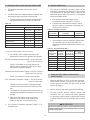
D. EXHAUST VENT AND INTAKE AIR VENT SIZING
E. LONGER VENT RUNS
1.
The exhaust and intake vent size is 3" for all
SE199’s.
2.
The total combined equivalent length of exhaust vent
and intake air pipe should not exceed 85 feet.
1. The maximum combined equivalent length can be
extended by increasing the diameter of both exhaust
vent and intake air vent pipe equally. However, the
transitions should begin a minimum of 15 equivalent
feet from the water heater.
a. The equivalent length of elbows, tees, and other
fittings are listed in the Friction Loss Table 3-5.
a. The maximum equivalent length for the
increased diameter vent pipes is 125 feet.
Table 3-5
b. Transitions should always be made in vertical
sections of pipe to prevent the condensate from
pooling in the vent pipe.
FRICTION LOSS EQUIVALENT IN PIPING AND FITTINGS
FITTINGS OR PIPING
EQUIVALENT FEET
3" (7.6 cm)
4" (10 cm)
90 DEGREE ELBOW*
5' (1.5 m)
3' (.92 m)
45 DEGREE ELBOW
3' (.92 m)
1' (.31 m)
COUPLING
0'
0'
AIR INLET TEE
0’
0’
STRAIGHT PIPE
1' (.31 m)
1' (.31 m)
CONCENTRIC VENT KIT SP12161
3' (.92 m)
N/A
V1100 3" VENT KIT SP12162
1' (.31m)
N/A
Table 3-6: Vent Run Transition
Vent
Reducing
Connection
Coupling
3" (7.6 cm)
4" × 3" (10 cm × 7.6 cm)
4" (10 cm)
c. If the transition occurs at a distance greater than
15 equivalent feet from the water heater, the
maximum equivalent length will be reduced. See
Table 3-7.
Table 3-7: Vent Termination Kits
Transition
TEL of
TEL of
Maximum TEL
Point
Standard
Oversized
of all
(ft from water
2” Vent
2”, 3” or 4”
V ent Pipe(ft)
heater)
Vent Pipe (ft)
Pipe (ft)
15 (4.58m)
30 (9.1 m)
95 (29 m)
125 (38 m)
*Friction loss for long radius elbow is 1 foot less
b. For example: If the exhaust vent has two 90°
elbows and 10 feet of PVC pipe we will calculate:
Exhaust Vent Pipe Equivalent Length = (2×5)+10=20 feet
(.61m×1.5m)+3m=6.1m
Further, if the intake air vent pipe has two 90°
elbows, one 45° elbow and 10 feet of PVC pipe,
the following calculation applies:
20 (6 m)
40 (12.2 m) 77-1/2 (23.6 m) 117-1/2 (35.9 m)
25 (7.6 m)
50 (15.2 m) 60-1/2 (18.4 m) 110-1/2 (33.7 m)
30 (9.1 m)
60 (18.2 m)
43 (13.1 m)
35 (10.7 m)
70 (21.3 m)
26 (7.92 m)
103 (31.4 m)
96 (29.2 m)
40 (12.2 m)
80 (24.3 m)
8-1/2 (2.6 m)
88-1/2 (27 m)
None
85 (27 m)
0
85 (26 m)
TEL = Total Equivalent Length
IntakeAir Vent Pipe Equivalent Length = (2×5)+3+10=23 feet
(.61m×1.5m)+.92m+3m=7m
F.
Finally, if a concentric vent kit is used we find:
Total Combined Equivalent Length = 20+23+3=46 feet
.61m+7m+.92m=14m
EXHAUST VENT AND INTAKE AIR PIPE
INSTALLATION
1. Use only solid PVC or CPVC for exhaust vent pipe.
FOAM CORE PIPING, as well as PVC and CPVC,
can be used for the intake vent pipe. Refer to chart
Section 3B, Page 11.
Therefore, the total combined equivalent length
is 46 feet which is well below the maximum of 85
feet.
2. Remove all burrs and debris from joints and fittings.
c. The intake air vent pipe and the exhaust vent are
intended to penetrate the same wall or roof of the
building.
3. All joints must be properly cleaned, primed, and
cemented. Use only cement and primer approved
for use with the pipe material. Cement must conform
to ASTM D2564 for PVC and ASTM F493 for CPVC
pipe.
d. Effort should be made to keep a minimum
difference in equivalent length between the
intake air vent pipe and the exhaust vent.
3.
Vent
Transition
WARNING
The minimum combined equivalent length is 16
equivalent feet.
All joints of positive pressure vent systems must be
sealed completely to prevent leakage of flue products
into the living space.
14
4.
Horizontal lengths of exhaust vent must slope back
towards the water heater not less than ¼” per foot
to allow condensate to drain from the vent pipe. If
the exhaust pipe must be piped around an obstacle
that results in the creation of a low point, condensate
will collect in this low point and form a blockage. This
condensate must be drained away using a fieldinstalled condensate drain assembly as shown. (See
page 19)
5.
All piping must be fully supported. Use pipe hangers
at a minimum of 4 foot (1.2 m) intervals to prevent
sagging of the pipe where condensate may form.
6.
Do not use the water heater to support any piping.
7.
COMBUSTION SETTINGS
HIGH FIRING RATES AND LOW FIRING RATES ON
ALL MODELS
Natural Gas
Propane LP
low
high
low
high
Carbon
Monoxide
(CO%)
0–10
ppm
0 ppm–
20 ppm
0–10
ppm
0 ppm–
20 ppm
Carbon
Dioxide
(CO2%)
8½% –
9½%
8½% –
9½%
9½% –
10½%
9½% –
10½%
FAN SPEED
A screened straight coupling is provided with the water
heater for use as an outside exhaust termination.
G. VERY IMPORTANT SET-UP INSTRUCTIONS!
IF YOU HAVE A COMBUSTION ANALYZER, THE FOLLOWING RATINGS WILL BE VERY HELPFUL IN SETTING UP YOUR SUPER-E SP:
15
BTU
IGNITION
MIN
MAX
199,000
3000
2000
8500
H. CONCENTRIC VENT
16
Note:
Spacing for multiple series of concentric vents should be the same as Multiple Vertical Vent in Fig. 3-3, P. 13.
LP-301-L Rev. 3/30/09
G. VENT LENGTH CROSS REFERENCE TABLE
FRICTION LOSS EQUIVALENCE TABLES
AFTER THE FIRST 10’ OF 3"
ONLY 4" EQUIVALENT TABLE
3" VENTED MODELS
FITTING
DESC.
EQUIVALENT
FEET
OF PIPE
3” 90
3” 45
3” Coupling
3” Tee
3” Pipe
3” Concentric vent kit
3” V1000 vent kit
5’
3’
0’
0’
1’ = 1’
3’
0’
EQUIVALENT
FEET
OF PIPE
FITTING
DESC.
4” 90
4” 45
4” Coupling
4” Pipe
4” Tee
3’
1’
0’
1’ = 1’
0’
VENTING EXAMPLES (NOTE: SHOWN AS INTAKE & EXHAUST PIPE AND FITTINGS ADDED TOGETHER)
* = MINIMUM VENT LENGTH
** = MAXIMUM VENT LENGTH
TOTAL
COMBINED
VENT LENGTH
(FEET)
INTAKE &
EXHAUST
*12
20
20
20
20
20
20
20
20
20
20
20
20**
30
30
30
30
30
30
30
30
30**
40
40
40
40
40
40
40**
50
50
50
50
50**
60
60
60**
70**
QTY.
OF 90°
ELBOWS
2
2
3
4
5
6
7
8
9
10
11
12
13
3
4
5
6
7
8
9
10
11
3
4
5
6
7
8
9
3
4
5
6
7
3
4
5
3
EQUIVALENT
FRICTION
LOSS
(FEET)
FOR EACH
ELBOW
5
5
5
5
5
5
5
5
5
5
5
5
5
5
5
5
5
5
5
5
5
5
5
5
5
5
5
5
5
5
5
5
5
5
5
5
5
5
17
TOTAL
FRICTION
LOSS
FOR
ELBOWS
10
10
15
20
25
30
35
40
45
50
55
60
65
15
20
25
30
35
40
45
50
55
15
20
25
30
35
40
45
15
20
25
30
35
15
20
25
15
GRAND TOTAL
VENT LENGTH
(FEET)
WITH FITTING
FRICTION
LOSS ADDED
22
30
35
40
45
50
55
60
65
70
75
80
85**
45
50
55
60
65
70
75
80
85**
55
60
65
70
75
80
85**
65
70
75
80
85**
75
80
85
85
PART 4: OPERATION
Function Value
d7 — Actual Ionization current read from Flame
Rectification probe
d8 — |0| (Not used)
d9 — |1| (Not used)
d10— Actual Status bus communication
|co| = connected, |nc| = not connected
d11 — |32| (Not used)
d12— Power On Hours (Example:Hours x 1000
Ex. 0.1 = 100 hrs. or 1.0 = 1000 hrs.
d13— Total Water Heating Hours (TW – Hrs. x 1000)
d14— |0| (Not used)
d15— Passed Ignition Attempts (Passed ignition x
1000)
A. OVERALL APPLIANCE AND CONTROL
OPERATION
C. TEST MODE
This function is intended to simplify the gas valve
adjustment if needed. Listed below are the recommended
limits on each Water Heater and the Combustion
Settings. Automatic modulation does not take place
when the controller is in Test mode, only temperature
limitation based on the Super-E SP set point. The
user will be allowed to increase or decrease the fan
speed by pressing in either the {S1/–} or {S2/+} keys.
To adjust temperature of the stored water press and hold
{S3} for 2 seconds. The first item is: |DU|: Water
Temperature Set Point – factory set at 119ºF, adjustable
down by pressing {S1} key to 70ºF and adjustable up by
pressing the {S2} key up to 159ºF. The {S3} key is then
pressed again momentarily to display |DH|, the differential
which is factory set at 7ºF and adjustable down to 1ºF by
pressing the {S1} key and up to 18ºF by pressing the {S2}
key. The {S3} key is pressed again momentarily to display
the choice of Fahrenheit “F” factory default or Celcius by
pressing the {S1} key. When finished, press the {S3} key
one final time to place unit back into operation. The
control automatically re-starts if no key is pressed for 2
minutes.
To activate the Test mode simply press the {S2/+} and
{S3/Program} key together for 1 second. Once
activated, you will see in the display |Ser| and the actual
fan speed. The measurement of the combustion
levels should always be taken at the highest and
lowest fan speed. After 10 minutes, the Test mode
stops automatically. To exit Test Mode press {S1/–} and
{S2/+} key together for 1 second.
B. STATUS MENU
Installers are also able to check the current status of the
Super-E SP parameters by pressing S4/RESET key for
3 seconds. Once activated, the display will show d1
alternating value of the actual upper supply tank
temperature. Actual values are displayed for each
function. To view the next value simply press the S/4} key
to go to the next displayed value. Listed below are the
values which can be displayed. These values cannot be
changed.
To
exit
this
menu,
simply
press
{S3/Program} key to resume normal operation.
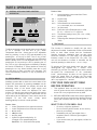
FOR YOUR OWN SAFETY READ
BEFORE OPERATING
Function
d1 —
d2 —
d3 —
d4 —
d5 —
d6 —
WHAT TO DO IF YOU SMELL GAS
Value
Actual Temperature from upper tank sensor
Actual Temperature from lower tank sensor
0 (Not used)
308 (Not used)
nc (Not used)
Actual Fan speed multiplied by 10
(Example: If fan speed displayed is
410 RPM x 10 = 4100 actual fan speed)
1.
This appliance does not have pilot. It is equipped
with an ignition device which automatically lights the
burner. Do not try to light the burner by hand.
2.
BEFORE OPERATING smell all around the appliance
area for gas. Be sure to smell next to the floor because
some gas is heavier than air and will settle on the
floor.
•
•
•
•
18
Do not try to light any appliance.
Do not touch any electric switch; do not use any
phone in your building.
Immediately call your gas supplier from a
neighbor’s phone. Follow the gas suppliers’
instructions.
If you cannot reach your gas supplier, call the fire
department.
3.
4.
5.
Turn on gas shutoff valve (located inside of the down
near burner) so that the handle is aligned with the gas
pipe. If the handle will not turn by hand, don’t try to
repair it, call a qualified service technician. Force or
attempted repair may result in a fire or explosion.
to any programming operations.
The control system requires no periodic maintenance
under normal conditions. However, in unusually dirty or
dusty conditions, periodic vacuuming of the cover to
maintain visibility of the display and indicators is recommended.
Do not use this appliance if any part has been under
water. Immediately call a qualified service technician
to inspect the appliance and to replace any part of the
control system and any gas control which has been
under water.
E. SHUTDOWN PROCEDURE
If the burner is operating, lower the set point value to
70°F (21°C) and wait for the burner to shut off. Continue
to wait for the combustion blower to stop so all latent
combustion gases are purged from the system. This
should take a maximum of 40 to 90 seconds, then
The Super-E SP shall be installed so the gas
ignition system components are protected from
water (dripping, spraying, rain, etc.) during appliance
operation and service (circulator replacement,
condensate trap, control replacement, etc.)
WARNING
D. OPERATING INSTRUCTIONS
Should overheating occur or the gas supply fail to
shut off, turn off the manual gas control valve to
the appliance.
If you smell gas, STOP. Follow listed safety instructions
above. If you do not smell gas, follow the next steps.
1. Turn on all electric power to appliance. Make sure
tank is full with cold water and purge all piping. To
assure adequate purging, open all hot water faucets.
2.
Adjust the temperature setpoint of the appliance if
desired. The factory default setting is 119° (48°C). If
changes are ncessary follow “Overall Appliance and
Control Operation” in this section.
3.
If the appliance fails to start, refer to the Troubleshooting section in the back of this manual.
WARNING
DO NOT use this appliance if any part has been under
water. Immediately call a qualified service technician
to inspect the appliance and to replace the water
heater if the control system or any gas control which
has been under water.
disconnect the electrical supply. If the burner is not operating, disconnect the electrical supply.
F. PREVENT COMBUSTION AIR CONTAMINATION
WARNING
Install intake air piping for the Super-E SP Water
When this water heater is supplying general purpose
hot water requirements for individuals, a thermostatically controlled mixing valve for reducing point of
use water temperature is recommended. Contact a
licensed plumber or the local plumbing authority for
further instructions.
WARNING
You must pipe outside air to the water heater air
intake. Ensure that the intake air will not contain
any of the contaminants below. Contaminated air
will damage the water heater, resulting in possible
severe personal injury, death or substantial property
damage. For example, do not pipe intake air vent
near a swimming pool. Also avoid areas subject to
exhaust fumes from laundry facilities. These areas
will always contain contaminants.
The three digit LED display will illustrate actual water
temperature within the tank under normal operating conditions. However, this display is also used to indicate the
temperature set point when in the programming mode.
The controller has a temperature set point range of 70°F
(21°C) to 159°F (70.5°C) (Booster models have a
maximum set point of 180°F [82°C]), with a factory
setting of 120°F (49°C).
Heater as described in the Venting section. Do not
terminate exhaust in locations that can allow
contamination of intake air.
NOTE: Power must be applied to the controller prior
CAUTION
In unusually dirty or dusty conditions, care must be
taken to keep appliance door in place. Failure to do
so VOIDS WARRANTY!
19
DANGER
G. CORROSIVE CONTAMINANTS AND SOURCES
Do not install the Super-E SP into a common
vent with any other appliance. This will cause flue
gas spillage or appliance malfunction, resulting in
possible severe personal injury, death or substantial
property damage.
PRODUCTS TO AVOID
Spray cans containing fluorocarbons
Permanent wave solutions
Chlorinated waxes/cleaners
Chlorine-based swimming pool chemicals
Calcium chloride used for thawing
Sodium chloride used for water softening
Refrigerant leaks
Paint or varnish removers
Hydrochloric acid/muriatic acid
Cements and glues
Antistatic fabric softeners used in clothes dryers
Chlorine-type bleaches, detergents, and cleaning solvents
found in household laundry rooms
Adhesives used to fasten building products and other
similar products
H. CONDENSATE
This is a condensing high efficiency appliance, therefore
this unit has a condensate removal system. Condensate
is nothing more than water vapor, derived from the combustion products, similar to an automobile when it is initially started. This condensate does have a low pH and
should be treated with a condensate filter. This filter contains either lime crystals or marble crystals, which will
neutralize the condensate. The outlet of the filter is sized
for 5/8" (1.6 cm) ID (inside diameter) plastic tubing. It is
very important that the condensate line is sloped away
from and down to a suitable inside drain. If the
condensate outlet on the Super-E SP is lower than the
drain, you must use a condensate removal pump. It is
also very important that the condensate line is not
exposed to freezing temperatures, or any other type of
blockage. Plastic tubing should be the only material used
for the condensate line. Steel, brass, copper, or other
metals will be subject to corrosion and deterioration. A
second vent may be necessary to prevent condensate
line vacuum lock if a long horizontal run is used. Also an
increase to 1" (2.5 cm) tubing may be necessary.
AREAS LIKELY TO HAVE CONTAMINANTS
Dry cleaning/laundry areas and establishments
Swimming pools
Metal fabrication plants
Beauty shops
Refrigeration repair shops
Photo processing plants
Auto body shops
Plastic manufacturing plants
Furniture refinishing areas and establishments
New building construction
Remodeling areas
Garages and workshops
NOTE: Always check local
evacuation of condensate.
codes
for
proper
FROM SUPER-E
Notes:
1. CONDENSATE LINE MUST BE PITCHED AT LEAST 1/4" PER FOOT (0.64 cm per 0.3 m)TO PROPERLY DRAIN. IF THIS CANNOT BE DONE OR A VERY LONG LENGTH OF
CONDENSATE HOSE IS USED YOU MUST INCREASE THE CONDENSATE LINE TO A MINIMUM OF 1" (2.5 CM) ID AND PLACE A TEE IN THE LINE AFTER THE
CONDENSATE NEUTRALIZER TO PROPERLY REDUCE VACUUM LOCK IN THE DRAIN LINE.
2. PLASTIC PIPE SHOULD BE THE ONLY MATERIAL USED FOR THE CONDENSATE LINE. STEEL, BRASS, COPPER OR OTHERS WILL BE SUBJECT TO CORROSION OR
DETERIORATION.
3. IT IS ALSO VERY IMPORTANT THAT THE CONDENSATE LINE IS NOT EXPOSED TO FREEZING TEMPERATURES, OR ANY OTHER TYPE OF BLOCKAGE.
20
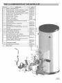
PART 5: COMPONENTS OF THE SUPER-E SP
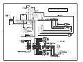
SUPER-E SP WIRING DIAGRAM
21
LP-301-D Rev. 3/30/09
MOST COMMON SUPER-E SP INSTALLATION CONCERNS
VENTING:
VENT LENGTH TOO LONG - OVER 85' (26 m)
VENTING NOT PITCHED PROPERLY - CONDENSATE BUILD UP IN VENT
EXHAUST GAS RE-CIRCULATION - VENT TERMINALS NOT USED, WRONG FITTINGS USED, SIGHT PROBLEMS
BUSH IN FRONT OF VENT TERMINAL
INSIDE CORNER OF BUILDING FOR VENT LOCATION
OVERHANG WITH VENT UNDERNEATH
COMPOUND ROOF PITCH, OR ABOVE ROOF FIRE WALL
ADDITIONAL FITTINGS INSTALLED INTO TERMINALS
VENT SIZED FROM 3" TO 4" BY USING BUSHINGS - INSTEAD OF REDUCING COUPLING OR REDUCING ELBOW
VENT CHANGED FROM 3" TO 4" - WITHOUT GOING REQUIRED 15' (4.6 m) ON BOTH INTAKE AND EXHAUST
VENTING NOT CLEANED AND GLUED TOGETHER FOR PRESSURE TIGHT JOINTS
INTAKE AIR CONTAINING EXHAUST FROM ANOTHER VENT OR APPLIANCE
GAS SUPPLY:
GAS PRESSURE TOO LOW - NEED 3.5" WC (0.87 kPa) GAS PRESSURE UP TO 14" WC (3.5 kPa) GAS PRESSURE
GAS METER TOO LOW IN CAPACITY
GAS REGULATOR NOT SIZED PROPERLY - TOO LOW IN CAPACITY
GAS PIPE TOO SMALL - 3/4" MINIMUM GAS SUPPLY SIZE
GAS REGULATOR TOO CLOSE TO APPLIANCE - NEED 10' OF PIPE FOR EVERY 200,000 BTU’S PER HOUR
GAS REGULATOR WITH LONG VENT OR BLEED VENT ORIFICE - REGULATOR SLOW TO RESPOND
GAS METER RESTRICTION, OR IN NEED OF REPAIR/REPLACEMENT
GAS SUPPLY PRESSURE DROPS BELOW 3.5" WC (0.87 kPa) WHEN APPLIANCE FIRES
ELECTRICAL:
APPLIANCE NOT GROUNDED
ELECTRICAL POLARITY REVERSED - FLAME WILL LIGHT BUT GO BACK OUT IN 4-6 SECONDS VOLTAGE TOO LOW OR TOO HIGH
APPLIANCE CYCLES, BUT NO IGNITION - REMOVE ANY CORROSION FROM SPARK ELECTRODE AND RECTIFIER. CHECK GAP
SPACING ON SPARK ELECTRODE. SHOULD BE 1/4" SPACING.
PLUMBING: DIELECTRIC UNIONS INSTALLED - RUSTY WATER
CONDENSATE:
CONDENSATE LINE NOT PITCHED TO DRAIN
CONDENSATE LINE NOT DRAINING DUE TO LONG RUN WITHOUT VENT
CONDENSATE PUMP NOT WORKING
CONDENSATE TRAP PLUGGED
BURNER:
EXTREMELY LOUD BANG ON IGNITION - BURNER FAILED OR END CAP OFF
RED BURNER DECK AS SEEN THROUGH VIEW PORT - GAS VALVE NEEDS ADJUSTMENT
GAS VALVE:
PUFFING ON IGNITION - ADJUST GAS VALVE
LOUD POP ON IGNITION, THEN RUNNING SMOOTH - ADJUST GAS VALVE
HUFF AND PUFF DURING OPERATION - ADJUST GAS VALVE
RUNNING GREAT BUT INTERMITTENTLY HUFFING OR POPPING - CHECK FOR RE-CIRCULATION UNDER VENTING
IT IS IMPORTANT TO NOTE FOR MAINTENANCE PURPOSES: THE THREAD ON THE END OF THIS GAS VALVE AND NIPPLE IS A
LEFT HAND THREAD.
SEALING SUPER-E SP AS PER N.S.F. STANDARD
NUMBER 5
TO SEAL THE BASE OF BOOSTER TO THE FLOOR TO
PREVENT SEE PAGE UNDERNEATH, PER N.S.F.
STANDARD #5 - APPLY A 3/8" BEAD OF RTV SILICONE
(AS SHOWN HERE), COMPLETELY AROUND TANK.
23
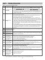
PART 6: TROUBLESHOOTING
Table 6-1: 926 Control Board Error Codes
Code Description
temperature switch
F00 High
limit exceeded
(194°F [90°C])
F01
F01 Vent temperature limit
exceeded
Remedy
1. Try reset, if F00 repeats, create a demand for hot water (n DANGER: use caution to prevent burn
injury) If water is above 194°F (90°C) test upper and lower temperature sensor with an ohmmeter.
(Refer to resistance chart, this section.) Replace bad sensor. If water is below 194° (90°C) test high
temperature switch and wiring with ohmmeter. Switch should be closed at this point, if not, replace switch.
2. If unit did reset successfully, let the unit run and go into the status menu to check the upper and lower
temperature sensor. If either reading displayed does not make sense, check appropriate sensor with
ohmmeter. (Refer to resistance chart this section.) Replace bad sensor. Do an OHMs reading on both
sensors to check continuity.
1. Inspect all flue piping. If the flue is damaged or shows signs of overheating then repair or replace the flue
parts as necessary before proceeding.
2. If the flue piping system is intact, not damaged and there is no sign of the flue overheating such as
discoloration or melting, then push the red reset button on the flue switch.
3. Be sure the unit is connected to a water supply and full of water.
4. Push the RESET button on the unit control panel. The appliance should light. If the appliance lights
proceed to step 5. If the appliance does not light and the display again begins to flash F01, inspect the
wiring to the flue switch, repairing or replacing as necessary. If the wiring is intact, replace the flue switch
using care to mount the new flue switch in the same position and mounting holes as the old one. If the
display flashes a code other than F01, follow the troubleshooting guide for that code.
5. Observe operation for 5 minutes. Place the probe of an exhaust analyzer into the flue system within 6
feet of the unit appliance. The exhaust temperature should not rise above 190°F (88°C) after several
minutes of operation.
6. If the flue temperature is below 190°F (88°C) and the appliance again goes into lockout displaying F01,
replace the flue switch using care to mount the new flue switch in the same position and mounting holes
as the old one. If the display flashes a code other than F01, follow the troubleshooting guide for that code.
7. If the flue temperature increases to over 190°F (88°C), Consult the Super-E SP factory for further
assistance.
or shorted
F02 Interrupted
upper temperature sensor Check the electrical connection to the appropriate temperature sensor, if connection is okay, replace bad
sensor.
Interrupted or shorted
F03 lower temperature sensor
temperature sensor
F05 Upper
If water in tank is not greater than 190°F (88°C), check wiring and repair if faulty. If the wiring is okay, check
exceeds 194°F (90°C)
appropriate sensor with ohmmeter and compare to reading in resitance chart. If reading does not agree with
Lower temperature sensor water temperature, replace bad sensor.
F06 exceeds 194°F (90°C)
No flame detected – The
unit will make three
F09F attempts at ignition before
the control goes into this
09
lockout condition. Will
reset in 1 hour.
Loss of Flame Signal –
The unit will relight 4 times
the control goes
F10F before
into this lockout condition.
10
Will reset in 1 hour.
False Flame Signal – The
F11F water heater will lock out if
11
it senses a flame signal
when there should be
none present.
1.
2.
3.
4.
5.
6.
1.
2.
3.
4.
5.
6.
1.
2.
3.
4.
Watch the igniter through the observation window provided.
f there is no spark, check the spark electrode for the proper ¼” (0.64 cm) gap.
Remove any corrosion from the spark electrode and flame rectifier probe.
If there is a spark but no flame, check the gas supply to the water heater.
If there is a flame, check the flame sensor.
Check any flue blockage or condensate blocks.
Monitor the gas pressure to the unit while in operation.
Assure that the flame is stable when lit.
Check to see if the green light on the display module is out while the water heater is running.
If the green light doesn’t come on or goes off during operation check the flame signal on the status menu.
If the signal reads less than 1 microampere, clean the flame rectifier probe.
If the flame rectifier probe continues to read low, replace it.
Turn the gas off to the unit at the service valve.
If the flame signal is still present replace the igniter.
If the flame signal is not present after turning off the gas supply, check the gas valve electrical connection.
If there is no power to the gas valve, remove the valve and check for obstruction in the valve seat or
replace the gas valve.
5. Turn the gas on at the service valve after corrective action is taken.
Combustion Fan Speed
Incorrect – The water
1. Check the combustion air fan wiring.
F13F heater will lock out if it
senses that the fan speed 2. Replace the combustion air fan.
13
is less than 70% of
3. Replace the control board.
expected rate for more
than 60 seconds.
NOTE: IF YOU REPLACE A PART TO REMEDY A FAULT, IT IS RECOMMENDED THAT YOU CYCLE THE UNIT AT
LEAST THREE OR FOUR TIMES TO ASSURE THE FAULT HAS BEEN RESOLVED.
24
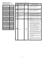
Table 6-2: Super-E SP
Resistance Table for Supply
Temperature Sensor
High/Low Temp.
Sensor Temp.
Resistance
(ohms)
32°F (0ºC)
32550
Table 6-3: 926 Control Board Error Codes
Code
E13E
13
Description
Duration
Corrective Action
Combustion Fan
Speed Low. The
combustion air fan
speed less than
70% of expected.
60 Sec.
1.
2.
3.
Check the combustion air fan wiring.
Replace the combustion air fan.
Replace the control board.
60 Sec.
1.
2.
3.
Check the combustion air fan wiring.
Replace the combustion air fan.
Replace the control board.
1.
2.
Be sure all air is bled from system.
Inspect low level switch and wiring for
damage and repair as necessary.
1.
2.
Assure that the vent is not blocked
Check the blocked vent pressure switch
operation by applying a jumper. (If the
switch is not functioning properly,
replace it.)
Check line voltage. Must be between
100-128 VAC.
If available, connect PC and using
Super-E SP service software check the
24 VAC supply display in the lower left
corner of the screen. The number
displayed here must be greater than
128 and should be greater than 250.
Use this as a troubleshooting guide as
you follow the steps below.
Remove 10 pin Molex connector from
customer connection board. If LOU
code clears, then the problem is with
external sensor wiring. Examine
external sensor wiring for shorts to
ground repairing as necessary. If LOU
code is still present and the boiler is so
equipped, disconnect high gas
pressure switch, then low gas pressure
switch, then UL 353 low water cutoff in
this order one at a time to see if LOU
code clears. Replace faulty part. Check
low voltage wire harness in boiler for
shorts to ground.
If LOU only occurs when burner tries to
light, check gas valve for excessive
current draw.
If LOU is present with the low voltage
harness disconnected from the 926
control board, replace the 926 control
board.
41°F (5ºC)
25340
50°F (10ºC)
19870
59°F (15ºC)
15700
68°F (20ºC)
12490
77°F (25ºC)
10000
86°F (30ºC)
8059
95°F (35ºC)
6535
104°F (40ºC)
5330
113°F (45ºC)
4372
FLU
122°F (50ºC)
3605
FLU
131°F (55ºC)
2989
1.
140°F (60ºC)
2490
2.
149°F (65ºC)
2084
158°F (70ºC)
1753
167°F (75ºC)
1481
176°F (80ºC)
1256
185°F (85ºC)
1070
194°F (90ºC)
915
202°F (95ºC)
786
212°F (100ºC)
667
Combustion Fan
Speed High. The
E14E combustion air fan
speed is more than
14
130% of expected.
LE0L
E0
Water level in tank
is low
Blocked Vent
Pressure Switch
Open
Until
Corrected
Until
Corrected
3.
LOU
OU
Until
Corrected
24 VAC low
4.
5.
25
HOW TO GET YOUR SUPER-E SP SERVICED
WARNING
If the information in these instructions are not followed exactly, a fire or explosion may result causing
property damage, personal injury or death.
FOR YOUR SAFETY!
— Do not store or use gasoline or other flammable
vapors or liquids or other combustible materials in
the vicinity of this or any other appliance. To do so
may result in an explosion or fire
— WHAT TO DO IF YOU SMELL GAS
• Do not try to light any appliance.
• Do not touch any electrical switch; do not use any
phone in your building.
• Immediately call your gas supplier from a neighbor’s
STEP I:
phone. Follow the gas supplier’s instructions.
• If you cannot reach your gas supplier, call the fire
department.
• Do not return to your building until authorized by
the gas supplier or fire department.
— Improper installation, adjustment, alteration, service
or maintenance can cause injury, property damage
or death. Refer to this manual. Installation and
service must be performed by a qualified installer,
service agency or gas supplier.
CALL YOUR INSTALLATION AND SERVICE CONTRACTOR
Your installation and service contractor should have read the installation instructions, and should
be capable of servicing the unit. Please contact them first. If the issue cannot be handled in this
way, continue as follows.
STEP II:
GATHER THE MODEL #, SERIAL #, AND DATE OF INSTALLATION
a) The Model # of your unit: this will either be a SE199-80 (80 gallon) or SE199-119,
b) The Serial # of your unit: this will be located on the label just to the left of the control box.
c) The installation date of your unit: you can determine this from your contractor or installation
invoice. If NATCO has received a warranty registration, we will be able to determine this for
you.
STEP IV: CALL NATCO TECHNICAL SUPPORT
a) Call NATCO Technical Support during normal business hours (Monday through Friday,
8:30am to 5:00 pm).
b) Email NATCO Technical Support at [email protected]. Have all of the
above information available. We will not be able to help you without model numbers and
serial numbers.
STEP V: EMAIL US FOR EMERGENCY SERVICE DURING NON-BUSINESS HOURS
c) Email [email protected] and someone will get back to you as soon as
possible. Have all of the above information available. We will not be able to help you without
model numbers and serial numbers.
26
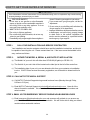
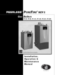
National Combustion Co., Inc.
104-11 180th Street
Jamaica, NY 11433
Ph: 718-291-8400
Fx: 718-291-6870
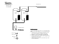
Hot Water Out
Super-E
PLT-12 FOR SE199-80,
DET-20 FOR SE199-118
Cold Water Supply
DRAWING: SE398160R
1 80 or 119 Gallon Super-E’s w/o recirculation line
Check Valve
Drain Valve
Ball Valve
Pump
Notes:
1. This drawing shows suggested piping configuration. Check
local codes and ordinances for additional requirements.
2. Minimum 1-1/2” cold water supply & hot water to store lines
recommended.
3. Back flow preventer may be required. Check local codes.
4. Thermal expansion tank is required.
5. Additional ball-valves, drain valves, and unions may be used
for ease of maintenance.
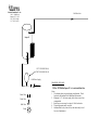
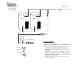
National Combustion Co., Inc.
104-11 180th Street
Jamaica, NY 11433
Ph: 718-291-8400
Fx: 718-291-6870
Hot Water Out
Super-E
Super-E
DET-20
Cold Water Supply
DRAWING: SE398160
2 80 or 119 Gallon Super-E’s w/o recirculation line
Check Valve
Drain Valve
Ball Valve
Pump
Notes:
1. This drawing shows suggested piping configuration. Check
local codes and ordinances for additional requirements.
2. Minimum 1-1/2” pipe size throughout is recommended.
3. Back flow preventer may be required. Check local codes.
4. Thermal expansion tank is required. NATCO suggests using 1
Watts DET-20 expansion tanks.
5. Additional ball-valves, drain valves, and unions may be used
for ease of maintenance.
National Combustion Co., Inc.
104-11 180th Street
Jamaica, NY 11433
Ph: 718-291-8400
Fx: 718-291-6870
Hot Water Out
Super-E
Super-E
DET-20
Cold Water Supply
DRAWING: SE398160R
2 80 or 119 Gallon Super-E’s w/ recirculation line
Check Valve
Drain Valve
Ball Valve
Pump
Notes:
1. This drawing shows suggested piping configuration. Check
local codes and ordinances for additional requirements.
2. Minimum 2” cold water supply & hot water to store lines recommended.
3. Minimum 1” recirculation line is recommended. 2” Optimal.
4. Back flow preventer may be required. Check local codes.
5. Thermal expansion tank is required. NATCO suggests using 1
Watts DET-35 expansion tanks.
6. Additional ball-valves, drain valves, and unions may be used
for ease of maintenance.
LIMITED WARRANTY
For National Combustion Co., Inc. Super-E Gas-Fired Water Heaters
GENERAL
This Limited Warranty is only available to the original owner of this water heater. It is not transferable.
National Combustion warrants this Super-E water heater, and its component parts, to be free from defects in
materials and workmanship, under normal use and service, for the Applicable Warranty period. At its option
National Combustion will repair or replace the defective Super-E water heater, or defective component part(s),
in accordance with the terms of this Limited Warranty, if it fails in normal use and service during the Applicable
Warranty Period. Any replacement water heater or replacement component part(s) must be authorized by
National Combustion. Replacement units will be warranted only for the unexpired portion of the original water
heater’s Applicable Warranty Period. Replacement parts will be warranted for 1 year.
EFFECTIVE DATE
The Effective date of warranty coverage (or the beginning of the Applicable Warranty Periods) is the date of
original installation of the Super-E water heater, if properly documented. Otherwise, it is the date of
manufacture of the Super-E water heater.
APPLICABLE WARRANTY PERIOD
The Super-E tank, including heat exchanger, is warranted for a total of 5 years from the Effective Date. Super-E
parts, including blower motor, controls, spark assembly,, sensors, etc. are warranted for 1 year from the Effective
Date.
WARRANTY EXCLUSIONS
This Limited Warranty will not cover:
a) Service trips to teach you how to install, use or maintain this Super-E water heater or to bring the Super-E
water heater’s installation into compliance with local building codes and regulations.
b) Damages, malfunctions, or failures resulting from failure to install the Super-E water heater in accordance
with applicable building codes/ordinances or good plumbing and electrical trade practices.
c) Damages, malfunctions, or failures resulting from improper installation or failure to operate and maintain
the Super-E water heater in accordance with the manufacturer’s instructions provided.
d) Performance problems caused by improper sizing of the Super-E water heater or the gas supply line, the
venting connection, combustion air openings, electric service voltage, wiring, or fusing.
e) Damages, malfunctions, or failures caused by improper conversion from natural gas to LP gas or LP gas to
natural gas fuel source.
f)
Damages, malfunctions or failures caused by operating the Super-E water heater with modified, altered, or
unapproved parts installed.
g) Damages, malfunctions, or failures caused by abuse, accident, fire, flood, freeze, lightning, acts of God,
and the like.
h) Tank failures (leaks) caused by operating the Super-E water heater in a corrosive or contaminated
atmosphere.
i)
Damages, malfunctions, or failures caused by operating the Super-E water heater with an empty, or
partially empty, tank (also known as “dry firing”).
j)
Damages, malfunctions, or failures caused by operating the Super-E unit at water temperatures exceeding
the maximum setting of the operating, or high limit, control.
k) Tank failures caused by operating the Super-E water heater when it is not supplied with potable water, free
to circulate at all times.
l)
Damages, malfunctions, or failures caused by subjecting the tank to pressures, or firing rates, greater than
those shown on the rating label.
m) Damages, malfunctions, or failures resulting from the use of any attachment, including any energy saving
device, not authorized by National Combustion.
n) Super-E units installed outside the fifty states (and the District of Columbia) of the United States of
America.
o) Super-E commercial units moved from the original installation location.
p) Super-E commercial units that have had their rating labels removed. A Super-E commercial water heater
should not be operated if the rating label is removed.
q) This water heater must be located in an area where leakage of the tank or water line connections and the
combination temperature and pressure relief valve will not result in damage to the area adjacent to the
water heater or to lower floors of the structure. When such locations cannot be avoided, a suitable drain
pan, adequately drained, be installed under the water heater.
LABOR, SHIPPING AND PROCESSING COST
This Limited Warranty does not cover any labor expenses for service, repairs, reinstallation, permits, or
removal and disposal of the failed Super-E water heater, or defective component part(s). All such expenses
are your responsibility.
National Combustion Co., Inc. does not authorize, recommend, or receive any benefit from any claims
processing or similar fees charged by other to process warranty claims for any Super-E water heater, or
component part(s). National Combustion Co., Inc. will not reimburse any party for these, or any other, fees
not specifically covered in this Limited Warranty document.
HOW TO OBTAIN WARRANTY CLAIM ASSISTANCE
Any claim for warranty assistance must be made promptly. First, determine if your Super-E water heater is
within the Applicable Warranty Period. You can determine your Super-E’s warranty status by obtaining
the complete model number, the complete serial number and the installation date of your Super-E water
heater by contacting National Combustion Co., Inc.’s Warranty Department (tel. no 718-291-8400) during
normal business hours to determine if the Applicable Warranty Periods have expired.
If your Super-E water heater is within the Applicable Warranty Period, contact the plumber, or mechanical
contractor, that installed it for assistance with the warranty repairs, or replacement, required. You may also
select a plumber, or mechanical contractor from your local Yellow Pages to assist you. National
Combustion’s Technical Service Department are available to assist you (tel. no. 718-291-8400) in
obtaining service or to answer your questions about the operation or repair of your Super-E commercial
water heater during normal business hours. Be prepared to provide the plumber, or mechanical contractor,
or National Combustion Co., Inc. technical service person you call wit the complete model number, the
complete serial number, and the date of installation of your Super-E water heater in addition to an
explanation of your Super-E water heater problem.
If an exact replacement is not available, National Combustion Co., Inc. will provide you with the current
model of your Super-E water heater, or component part(s), or a replacement unit with comparable
operating features. If government regulations or industry certification or similar standards require the
replacement Super-E water heater, or replacement component part(s), to have features not found in the
defective Super-E commercial water heater, or the defective component part(s), you will be charged for the
difference in price represented by those required features. If you pay the price difference for those required
features and/or to upgrade the size and/or other features available on a replacement new Super-E water
heater, you will also receive a complete new Limited Warranty (with the full Applicable Warranty Period)
for the replacement new Super-E water heater.
DO NOT DESTROY, OR DISPOSE OF, ANY SUPER-E OR DEFECTIVE PART(S) WITHIN THE
APPLICABLE WARRANTY PERIOD. NATIONAL COMBUSTION HOLDS THE RIGHT TO
REQUIRE ANY SUPER-E UNIT OR COMPONENT PART(S) TO BE RETURNED (WITH ORIGINAL
RATING LABEL AND COMPONENT PARTS INTACT) IN EXCHANGE FOR THE REPLACEMENT
UNIT. Each defective component part within the applicable warranty period to be replaced must be
returned to National Combustion Co., Inc. in exchange for the replacement component part.
Warranty compensation is subject to validation of applicable warranty period coverage by National
Combustion Co., Inc. Claims Department personnel.
To obtain warranty compensation for an “in-warranty” water heater failure, you must provide
National Combustion Co., Inc., at the option of National Combustion Co., Inc., either (i) the failed
Super-E unit (with rating label and all the component parts intact); the complete model number and
the complete serial number of the Super-E that replaced the failed Super-E unit.; and, the date the
original Super-E water heater failed, or (ii) the complete Super-E rating label, without which it should
never be operated; the complete model number and the complete serial number of the Super-E that
replaced the failed Super-E unit.; and, the date the original Super-E water heater failed.
To receive warranty compensation for component parts within the applicable warranty period, you
must provide National Combustion Co with: the defective component part; the complete model
number and the complete serial number of the Super-E water heater from which the defective
component part was removed; and, the date the defective part failed. You may also be required to
provide documentary proof of the date of installation of the water heater from which the defective
component part was removed – or the date of purchase of the component part (if it was purchased
separately) – to establish the “in-warranty” status of the defective component part.
Warranty claim documentation should be mailed promptly to National Combustion Co., Inc., Warranty
Dept., 104-11 180th Street, Jamaica, NY 111433.
EXCLUSIVE WARRANTY – LIMITATION OF LIABILITY
This Limited Warranty is the only Warranty for this unit given by National Combustion Co., Inc. No one
is authorized to make any other warranties on behalf of National Combustion Co., Inc. ANY IMPLIED
WARRANTIES, INCLUDING MERCHANTABILITY, OR FITNESS FOR A PARTICULAR
PURPOSE, SHALL NOT EXTEND BEYOND THE APPLICABLE WARRANTY PERIODS
SPECIFIED PREIVIOUSLY. NATIONAL COMBUSTION CO., INC.’S SOLE LIABILITY, WITH
RESPECT TO ANY DEFECT, SHALL BE AS SET FORTH IN THIS LIMITED WARRANTY, AND
ANY CLAIMS FOR INCIDENTAL OR CONSEQUENTIAL DAMAGES (INCLUDING DAMAGE
FROM WATER LEAKAGE) ARE EXCLUDED. Some states do not allow limitations on how long an
implied warranty lasts, or for the exclusion of incidental or consequential damages, so the above limitations
may not apply to you.
CERTIFICATE
OF LIMITED
WARRANTY
This Limited Warranty gives you specific legal rights, and you may also have other rights, which vary from
state to state.
We suggest you immediately complete the information on the attached warranty information form in the
event warranty service is needed. Reasonable proof of the date of installation of your Super-E water heater
may be required to establish its applicable warranty period. Otherwise the Effective Date of the Limited
Warranty will be the date of manufacture of the Super-E water heater plus ninety (90) days.
DO NOT RETURN THIS DOCUMENT TO NATIONAL COMBUSTION CO., INC.
KEEP IT WITH YOUR SUPER-E WATER HEATER OR BUSINESS RECORDS.
Name of Owner/Business Location
Where Unit is installed:
________________________________________________
Super-E Water Heater Installation Address: _________________________________________
________________________________________________
Date Super-E Water Heater was Installed: __________________________________________
Name of Plumber/Mechanical Contractor – Installer: _________________________________
Plumber/Mechanical Contractor – Installer’s Address:_________________________________
____________________________________________________________________________
Complete Model # of the Super-E: ________________________________________________
Complete Serial Number of the Super-E:___________________________________________
SUPER-E
GAS-FIRED WATER HEATER