1
5500906
AUTO - INDEX
SPIN / RELIEF
REEL GRINDER
Patent No. 5,321,912
6,010,394 & 6,290,581
ASSEMBLY
and
SERVICE
MANUAL
1
55006 (11-03)
SAFETY INSTRUCTIONS
Safety Awareness Symbols are inserted
into this manual to alert you to possible
Safety Hazards. Whenever you see these
symbols, follow their instructions.
The Warning Symbol identifies
special instructions or procedures
which, if not correctly followed,
could result in personal injury.
The Caution Symbol identifies special
instructions or procedures which, if not
strictly observed, could result in damage to
or destruction of equipment.
1. KEEP GUARDS IN PLACE and in working
order.
12. DON'T OVERREACH. Keep proper footing and
balance at all times.
2. REMOVE WRENCHES AND OTHER
TOOLS.
13. MAINTAIN GRINDER WITH CARE. Follow
instructions in Service Manual for lubrication and
preventive maintenance.
3. KEEP WORK AREA CLEAN.
14. DISCONNECT POWER BEFORE SERVICING,
or when changing the grinding wheel.
4. DON'T USE IN DANGEROUS ENVIRONMENT.
Don't use Grinder in damp or wet locations.
Machine is for indoor use only. Keep work area well 15. REDUCE THE RISK OF UNINTENTIONAL
lit.
STARTING. Make sure all switches is OFF before
plugging in the grinder.
5. KEEP ALL VISITORS AWAY. All visitors
should be kept a safe distance from work area.
16. USE RECOMMENDED ACCESSORIES. Consult
the manual for recommended accessories. Using
6. MAKE WORK AREA CHILD-PROOF with
improper accessories may cause risk of personal
padlocks or master switches.
injury.
7. DON'T FORCE THE GRINDER. It will do the job
better and safer if used as specified in this
manual.
17. CHECK DAMAGED PARTS. A guard or other
part that is damaged or will not perform its
intended function should be properly repaired or
replaced.
8. USE THE RIGHT TOOL. Don't force the grinder
or an attachment to do a job for which it was not 18. KNOW YOUR EQUIPMENT. Read this manual
designed.
carefully. Learn its application and limitations as
well as specific potential hazards.
9. WEAR PROPER APPAREL. Wear no loose
clothing, gloves, neckties, or jewelry which may 19. KEEP ALL SAFETY DECALS CLEAN AND
get caught in moving parts. Nonslip footwear is
LEGIBLE. If safety decals become damaged or
recommended. Wear protective hair covering to
illegible for any reason, replace immediately.
contain long hair.
Refer to replacement parts illustrations in Service
Manual for the proper location and part numbers
10. ALWAYS USE SAFETY GLASSES.
of safety decals.
11. SECURE YOUR WORK. Make certain that the
cutting unit is securely fastened with the clamps
provided before operating.
20. DO NOT OPERATE THE GRINDER WHEN
UNDER THE INFLUENCE OF DRUGS,
ALCOHOL, OR MEDICATION.
2
SAFETY INSTRUCTIONS
IMPROPER USE OF GRINDING WHEEL MAY CAUSE
BREAKAGE AND SERIOUS INJURY.
Grinding is a safe operation if the few basic rules listed below are followed. These rules are based on material
contained in the ANSI B7.1 Safety Code for "Use, Care and Protection of Abrasive Wheels". For your safety,
we suggest you benefit from the experience of others and follow these rules.
DON'T
DO
1. DO always HANDLE AND STORE
wheels in a careful manner.
1. DON'T use a cracked wheel or one that HAS BEEN
DROPPED or has become damaged.
2. DO VISUALLY INSPECT all wheels before
mounting for possible damage.
2. DON'T FORCE a wheel onto the machine OR
ALTER the size of the mounting hole--if wheel won't
fit the machine, get one that will.
3. DO CHECK MACHINE SPEED against the
established maximum safe operating speed
marked on wheel.
3. DON'T ever EXCEED MAXIMUM OPERATING
SPEED established for the wheel.
4. DON'T use mounting flanges on which the bearing
surfaces ARE NOT CLEAN, FLAT AND FREE OF
BURRS.
4. DO CHECK MOUNTING FLANGES for equal
and correct diameter.
5. DO USE MOUNTING BLOTTERS when supplied
with wheels.
5. DON'T TIGHTEN the mounting nut EXCESSIVELY.
6. DO be sure WORK REST is properly
adjusted.
6. DON'T grind on the SIDE OF THE WHEEL (see
Safety Code B7.2 for exception).
7. DO always USE A SAFETY GUARD COVERING
at least one-half of the grinding wheel.
7. DON'T start the machine until the WHEEL GUARD
IS IN PLACE.
8. DO allow NEWLY MOUNTED WHEELS to run at
operating speed, with guard in place, for at least
one minute before grinding.
8. DON'T JAM work into the wheel.
9. DON'T STAND DIRECTLY IN FRONT of a
grinding wheel whenever a grinder is started.
9. DO always WEAR SAFETY GLASSES or some
type of eye protection when grinding.
10. DON'T FORCE GRINDING so that motor slows
noticeably or work gets hot.
AVOID INHALATION OF DUST generated by grinding and cutting operations. Exposure
to dust may cause respiratory ailments. Use approved NIOSH or MSHA respirators,
safety glasses or face shields, and protective clothing. Provide adequate ventilation to
eliminate dust, or to maintain dust level below the Threshold Limit Value for nuisance
dust as classified by OSHA.
3
TABLE OF CONTENTS
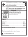
This machine is intended for grinding the reel of reel type mower units ONLY.
Any use other than this may cause personal injury and void the warranty.
To assure the quality and safety of your machine and to maintain the warranty,
you MUST use original equipment manufactures replacement parts and have any
repair work done by a qualified professional.
ALL operators of this equipment must be thoroughly trained BEFORE operating
the equipment.
Do not use compressed air to clean grinding dust from the machine. This dust
can cause personal injury as well as damage to the grinder. Machine is for
indoor use only. Do not use a power washer to clean the machine.
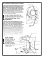
Low Voltage Relay
The grinder is equipped with a low voltage relay which
is factory preset at 100 VAC. If the power supply line
does not deliver 100 VAC power under load, the relay
will open and trip out the starter. If this occurs, your
power supply line is inadequate and must be correct
before proceeding further with the grinder.
CONTENTS
Safety Instructions .................................................................................................................... Page 2-5
Daily Maintenance .................................................................................................................... Page 4
Service Data.............................................................................................................................. Page 6
Assembly Instructions ............................................................................................................... Page 7-12
Maintenance.............................................................................................................................. Page 13-19
Adjustments .............................................................................................................................. Page 20-25
Electrical Troubleshooting ......................................................................................................... Page 26-41
Mechanical Troubleshooting ..................................................................................................... Page 42-43
Exploded Views and parts Lists ................................................................................................ Page 44-75
DAILY MAINTENANCE BY THE OPERATOR
On a daily basis, clean the machine by wiping it off.
On a daily basis, remove all grinding grit from the grinding shaft, traverse shafts, and tooling bar
area.
On a daily basis, inspect the machine for loose fasteners or components.
Contact your company's Maintenance Department if damaged or defective parts are found.
DO NOT USE COMPRESSED AIR TO CLEAN
GRINDING DUST FROM GRINDER
4
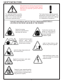
SAFETY INSTRUCTIONS
Safety Awareness Symbols are inserted in this
manual to alert you to possible Safety Hazards.
Whenever you see these symbols, heed their
instructions.
The Warning Symbol identifies
special instructions or procedures
which, if not correctly followed,
could result in personal injury.
The Caution Symbol identifies special
instructions or procedures which , if not
strictly observed, could result in damage
to, or destruction of equipment.
PLEASE TAKE SPECIAL NOTE OF THE FOLLOWING WARNING DECALS
LOCATED ON THE FRONT AND SIDES OF THE GRINDER.
Symbol for hearing
protection required when
operating this machine.
Symbol that operator and
people in close proximity
must wear respirators or
have an adequate
ventilation system.
Symbol for Read operators
manual, wear safety
glasses and disconnect
power before servicing.
Symbol to keep visitors a safe
distance away from the grinder.
Symbol for sharp object which will
cause serious injury.
Symbol identifying a panel, cover,
or area as having live electrical
components within.
Symbol for minimum safe rated
RPM of grinding wheel.
Symbol to keep exposed gasoline
or flammables away from the
grinder because it operates with a
large amount of sparks.
5
SERVICE DATA
SKILL AND TRAINING REQUIRED FOR SERVICING
This Service Manual is designed for technicians who have the necessary mechanical and electrical
knowledge and skills to reliably test and repair the 550 Spin/Relief Grinder. For those without the background,
service can be arranged through your local distributor.
This section presumes that you are already familiar with the normal operation of the Grinder. If not, you
should read the operators manual, or do the servicing in conjunction with someone who is familiar with its
operation.
Persons without the necessary knowledge and skills should not remove the control box cover or attempt any
internal troubleshooting, adjustments, or parts replacement.
If you have questions not answered in this manual, please call your distributor. They will contact the
manufacturer if necessary.
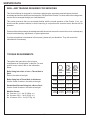
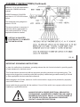
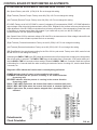
TORQUE REQUIREMENTS
Throughout this manual we refer to torque
requirements as "firmly tighten" or the like. For more
specific torque values, refer to the information
below.
GRADE 2
Bolts Going Into a Nut, or Into a Thread Hole in
Steel.
Refer to the table at the right.
Bolts Going Into a Thread Hole In Aluminum
Use the Grade 2 values in the table at the right.
SMOOTH
HEAD
3 MARKS
on HEAD
1/4 In.
thread
6 ft-lbs
(0.8 kg-m)
9 ft-lbs
(1.25 kg-m)
13 ft-lbs
(1.8 kg-m)
5/16 In.
thread
11 ft-lbs
(1.5 kg-m)
18 ft-lbs
(2.5 kg-m)
28 ft-lbs
(3.9 kg-m)
31 ft-lbs
(4.3 kg-m)
46 ft-lbs
(6.4 kg-m)
75 ft-lbs
(10.4 kg-m)
3/8 In.
thread
Socket-Head Screws Going Into a Nut or Steel
Use the Grade 8 values in the table at the right.
Machine Screws
No. 6 screws: 11 in.- lbs (0.125kg - m)
No. 8 screws: 20 in. - lbs (0.23 kg - m)
No. 10 screws: 32 in. - lbs (0.37 kg - m)
6
GRADE 5 GRADE 8
19 ft-lbs
(2.6 kg-m)
6 MARKS
on HEAD
7/16 In.
thread
30 ft-lbs
(4.1 kg-m)
50 ft-lbs
(6.9 kg-m)
1/2 In.
thread
45 ft-lbs
(6.2 kg-m)
75 ft-lbs
115 ft-lbs
(10.4 kg-m) (15.9 kg-m)
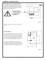
ASSEMBLY INSTRUCTIONS
Remove the sides, front, and back of the crate.
Remove the plastic bag, shrink wrap and bubble
wrap. Remove the metal clips that secure the
grinder to the crate base. With a fork lift, raise the
grinder from the wood base and set it in its final
position. See FIG. 22 and 23.
THE UNIT WEIGHS
1240 LBS. (562 kg). TO
LIFT, USE POWER
EQUIPMENT.
FIG. 22
Remove shipping straps and window protective
sheets.
POSITION BASE
The 550 Spin/Relief Grinder will require an operating area of about 150" W x 110" D x 87" H (381 x
279 x 221 cm). The machine operator will operate
the unit from the front of the machine. Position the
base to allow sufficient operating room in front and
to the rear of the machine. See FIG. 22 and 23.
The base should be placed on a relatively level
concrete floor, with ample ceiling height to allow for
the installation of the unit. Do not place the unit across
two concrete slab seams or across a large crack.
FIG. 23
7
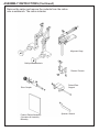
ASSEMBLY INSTRUCTIONS (Continued)
Remove the carton and remove the contents from the carton
onto a workbench. The carton includes:
Alignment Gage
Multi position Brackets
Diamon Dresser
Raised Rear
Support
Drive Coupler
Spanner Wrench
Product Packet Assembly
(Operators & Assembly
Manuals)
8
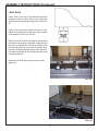
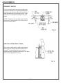
ASSEMBLY INSTRUCTIONS (Continued)
LEVEL BASE
Place level on the top of the table and check the
levelness of the unit from side to side. Adjust the
leveling feet as necessary to bring to level. See FIG.
25.
Place a level across the table from front to rear.
Adjust the leveling feet on the end of the machine
as necessary to level. See FIG. 26.
FIG. 24
When both front to back and side to side leveling
procedures have been completed, thread the hex
jam nuts up against the nut that is welded to the
bottom until they lock into place. Be careful not to
move the leveling feet during this process. See FIG.
24. Make certain that all four leveling feet are firmly
contacting the floor.
Recheck with level after locking nuts are firmly
tightened.
FIG. 25
FIG. 26
9
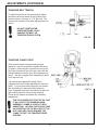
ASSEMBLY INSTRUCTIONS (Continued)
APPLY POWER
BEFORE YOU APPLY POWER TO THE
GRINDER, REFER TO THE "IMPORTANT
GROUNDING INSTRUCTIONS".
115 Volt Model Only. Plug the control box power cord into a
standard 115V AC 20-amp grounded receptacle. See FIG. 27.
FIG. 27
220 Volt Model Only. For 220 Volt Applications order Part
No. 5500956, which includes a prewired 2 KVA 220 V step
down to 115V 50-60 Hz transformer. See details on Page
11.
IT IS RECOMMENDED THAT THIS SPIN/
RELIEF GRINDER HAS ITS OWN
The grinder is equipped with a low voltage relay
PERMANENT POWER CONNECTION FROM
which is factory preset at 100 VAC. If the power
THE POWER DISTRIBUTION PANEL, WITH
supply line does not deliver 100 VAC power under
NO OTHER MAJOR POWER DRAW
load, the relay will open and trip out the starter. If
EQUIPMENT ON THE SAME LINE.
this occurs, your power supply line is inadequate
and must be correct before proceeding further with
IT IS REQUIRED THAT THE POWER
DELIVERED TO THIS GRINDER IS 115 VAC - the grinder.
20 AMPS. THE TOLERANCE ON THIS
POWER REQUIREMENT IS +/- 5%.
THEREFORE THE MINIMUM VOLTAGE
REQUIREMENT IS 109VAC WITH 20 AMPS.
VOLTAGE MUST BE CHECKED WITH ALL
EQUIPMENT UNDER LOAD (OPERATING) ON
THE CIRCUIT.
DO NOT OPERATE THIS GRINDER WITH
AN EXTENSION CORD.
PROPER GROUNDING OF THE
RECEPTACLE GROUND IN YOUR BUILDING
MUST BE VERIFIED. IMPROPER
GROUNDING IN YOUR BUILDING MAY
CAUSE THE GRINDER TO MALFUNCTION.
FOR 20 AMP RATED LARGE MACHINES
Below is a list of required wire size in your building.
For 0 to 40 Feet from panel to receptacle = Use 12 Ga. Wire.
For 40 to 60 Feet from panel to receptacle = Use 10 Ga. Wire.
For 60 to 100 Feet from panel to receptacle = Use 8 Ga. Wire.
For 100 to 160 Feet from panel to receptacle = Use 6 Ga. Wire.
For 0 to 12 Meters from panel to receptacle = Use 4.0mm Wire.
For 12 to 18 Meters from panel to receptacle = Use 6.0mm Wire.
For 18 to 30 Meters from panel to receptacle = Use 10.0mm Wire.
For 30 to 48 Meters from panel to receptacle = Use 16.0mm Wire.
10
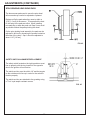
ASSEMBLY INSTRUCTIONS (Continued)
FOR 220 V 50 or 60Hz applications
Product No. 5500956 should be
ordered.
5500956 includes a 2 KVA 220V,
step down to 115 V 50-60 Hz transformer.
The transformer wiring diagram is
shown in FIG. 28.
The power cord has no connector. A
connector which is appropriate for
your locality and 220 volt, 10 amp
application should be installed.
USE ONLY A QUALIFIED
ELECTRICIAN TO COMPLETE
THE INSTALLATION.
FIG. 28
IMPORTANT GROUNDING INSTRUCTIONS
In case of a malfunction or breakdown, grounding reduces the risk of electrical shock by providing a path
of least resistance for electrical current.
This Grinder has an electrical cord with an equipment grounding conductor and a grounding plug. The
plug must be plugged into a matching outlet that is properly installed and grounded according to all local
or other appropriate electrical codes and ordinances.
Before plugging in the Grinder, make sure it will be connected to a supply circuit protected by a properly
sized circuit breaker or fuse.
Never modify the plug provided with the machine--if it won't fit the outlet, have a proper outlet and circuit
installed by a qualified electrician.
ALWAYS PROVIDE A PROPER ELECTRICAL GROUND FOR
YOUR MACHINE. AN IMPROPER CONNECTION CAN CAUSE A
DANGEROUS ELECTRICAL SHOCK. IF YOU ARE UNSURE OF
THE PROPER ELECTRICAL GROUNDING PROCEDURE,
CONTACT A QUALIFIED ELECTRICIAN.
11
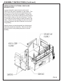
ASSEMBLY INSTRUCTIONS (Continued)
INSTALLATION OF OPTIONAL WINCH AND
BOOM KIT 55522
If you purchased the optoinal winch and boom kit
(55522) you will need to assemble it to the grinder. First
remove the left side polycarbonate guarding and save
the fasteners to use on the new guarding. Position the
boom base on the left side so that the mounting brackets
line up with the holes on the side of the frame. Use the
1/2 inch bolts and lock washers to fasten the base to the
frame. Position the new guarding into place and use the
remaining fasteners and the old fasteners to mount the
new guarding.
Place the boom and winch assembly into the base and
attach the spreader bar assembly. Remove the rubber
grommet from the old guarding and place in the new
guarding.
FIG. 29
12
PERIODIC MAINTENANCE
DAILY MAINTENANCE IS SPECIFIED ON PAGE 4
OF THE OPERATOR'S MANUAL, AND IS TO BE
PERFORMED BY THE OPERATOR.
LISTED BELOW ARE PERIODIC MAINTENANCE
ITEMS TO BE PERFORMED BY YOUR
COMPANY'S MAINTENANCE DEPARTMENT:
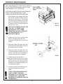
1. Clean the dust tray located at the lower
front of the machine monthly using a
vacuum or by removing it. Pull the tray
out until the back of the tray is even with
the front of the frame and vacuum it out.
To remove continue to pull straight out
until the tray is free.
FIG. 30
USE CAUTION WHEN PULLING THE
TRAY OUT AS THERE IS NO
MECHANICAL STOP. WHEN
REMOVING TRAY PULL STRAGHT
OUT AND SUPPORT IT TO
PREVENT DUMPING.
2. Inspect the Poly-V belt on the grinding
motor for cracking and make any
necessary adjustments every three
months.
3. Wipe and relube with never-seez, the
horizontal adjustment shafts located on
the tooling every six months.
4. Wipe and relube with never-seez, the
vertical adjustment shafts every six
months. Run the arms up and down to
coat the working areas of the shaft.
FIG. 31
5. Inspect the traverse cog belt for
cracking and defects every three months.
Remove any grit or dust that may affect
the function of the belt. Adjust tension if
necessary per procedures called out in
the adjustment section.
6. Lubricate grinding shaft bearings with
one shot of grease once every 2
years.
DO NOT GREASE BEARINGS FOR
FIRST 2 YEARS. THEY ARE
GREASED AT THE FACTORY AND
GREASING WILL CAUSE THE
BEARINGS TO OVERHEAT AND FAIL
PREMATURELY.
13
LUBRICATION
LUBRICATION OF GRINDING SHAFT AND LINEAR BEARINGS
STEP 1 – Thoroughly clean all three shafts.
STEP 2 – Flood spray all three shafts with WD40 until the lubricant is dripping off the shafts. Then run
the grinding head assemblies back and forth through their full range of travel. This will remove the
dust and deposits from inside the wheel flanges. Repeat if necessary until lubrication is clear of
deposits. Clean keyways located on the grinding shaft with soft brush.
STEP 3 – With a clean rag, wipe off the excess amount of lubricant from the shafts. Run the grinding
assemblies through their range of travel and wipe the shafts after each traverse. Repeat until the
shafts are dry to the feel. This completes the lubrication process.
If the unit will be shut down for an extended period of time, more than four weeks, then the shafts and
other appropriate parts of the unit should be flooded with lubricant and that lubricant left in place until
the unit is brought back into service. When the unit is brought back into service the full lubrication
procedure as stated above should be repeated.
FIG. 32
14
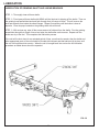
MAINTENANCE
REPLACEMENT OF GRINDING WHEEL
To replace the wheel first open the Polycarbonate
guarding located on the left side of the machine. Now,
lower the left side of the grinding shaft and raise the
right side. Loosen the two bolts that hold the bearings
on the relief hub so that that bearings fall away from the
wheel and hub (toward the front of the machine).
Press the index finger down and the wheel and hub
assembly should move freely to the right. Loosen the
setscrews on the bearing and remove the screws that
hold the bearing to the left arm.
Remove the bearing and lift the left end of the grinding
shaft. Slide the grinding wheel hub assembly(s) off the
shaft taking note of what side the nut is on. Using the
spanner wrench (50014) remove and replace the
grinding wheel(s) on the hub assembly.
BEARING
RELIEF FLANGE
RELIEF WHEEL
RELIEF NUT
SPIN NUT
SPIN WHEEL
SPIN FLANGE
FIG. 33
NOTE: THE RELIEF HUB HAS A LEFT
HAND THREAD FOR THE NUT. THE SPIN
HUB HAS A RIGHT HAND THREAD.
Place the ginding wheel hub assembly(s) back on the
grinding shaft and make sure the spin hub is located
between the drive yoke assembly and the relief hub is
to the right of the drive assembly.
MAKE SURE THE WHEEL(S) IS PLACED ON
THE SHAFT WITH THE SAME ORIENTATION AS
SHOWN. FAILURE TO INSTALL CORRECTLY
WILL CAUSE THE WHEEL NUT TO LOOSEN.
(THE NUT ON THE RELIEF HUB SHOULD BE
TO THE RIGHT & THE NUT ON THE SPIN HUB
SHOULD BE TO THE LEFT.)
Loosen bolts and tip back.
Press in indexing finger and
the wheel should slide freely
to the right.
Reinstall the bearing on the left side of the shaft making
sure to fit the pilot on the bearing into arm. Tighten
mounting screws, and tighten the setscrews to the
shaft. Close and tighten polycarbonate guard. Move
bearing support back in place - see relief hub bearing
adjustment complete details.
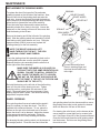
WHEEL DRESSING
FIG. 34
spin grinding wheel into the dresser and then move
the grinding wheel side to side against the dresser
which will dress the full face of the wheel.
If the grinding wheel becomes loaded with material it
may be necessary to dress the wheel. The 550 is
supplied with a diamond dresser. To use, place the
dresser on the spin drive horizontal arm in the area
where the wheel is to be dressed. Adjust the dresser
to the appropriate position and angle. Raise the
grinding wheel so it is nearly touching the dresser.
For dressing the spin grinding wheel, put the dresser in
the straight position. Close the doors and infeed the
15
For dressing the relief wheel, put the dresser at the
correct angle for normal helix reel or reverse helix
reel. See pages 24 and 25 of the Operators Manual.
Close the doors and infeed the relief grinding wheel
into the dresser. Do Not move the grinding wheel
from side to side.
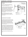
MAINTENANCE (CONTINUED)
GRINDING MOTOR BELT REPLACEMENT/
ALIGNMENT
To replace or inspect the grinding motor belt,
remove the rear side panel. To remove the belt,
pull down on the tensioner pulley.
For the belt to function properly the grinding shaft
pulley and the grinding motor pulley must be in line
with the tensioner pulley. To adjust the pulley
position loosen the setscrews on the pulley.
Locate the belt in the center of the idler pulley.
Measure from the arm to the edge of the belt at the
idler pulley. Adjust the two other pulley's until the
same measurement is achieved and tighten the
pulley setscrews.
Before reinstalling the rear panel, run the grind
motor to assure that the belt is not misaligned.
The belt will walk off the pulley if the system is not
aligned properly.
FIG. 35
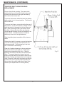
TRAVERSE BELT REPLACEMENT
To replace the traverse belt first loosen the nuts on
the left side pulley that are used to tension the belt.
Remove the right side rear side panel. Loosen the
screws holding the traverse motor and tilt the
bottom of the motor out releasing any remaining
tension on the belt. On the left side remove the nut
from the bottom belt tensioning screw, this will allow
the belt to be removed.
Place a new belt on the left pulley making sure it is
seated properly in the cogged teeth and replace the
locknut. Feed the new belt throught the slot on the
right arm and place on motor pulley. Use the motor
as a lever to apply tension to the new belt. Tighten
motor screws and adjust the tension in the belt as
specified in the BELT TENSION section. Adjust the
height of the motor pulley if necessary so the belt is
located in the center of the traverse belt clamp.
FIG. 36
Test the traverse motor and replace the rear side
panel.
16
MAINTENANCE (CONTINUED)
TRAVERSE SHAFT/LINEAR BEARING
REPLACEMENT
Remove the left side guarding. Then remove the
grinding shaft by removing the left side bearing and
loosening the setscrews on the right side bearing.
Also remove the traverse belt.
To remove the traverse shafts first lower the grinding
shaft so that it is in in's lowest position. Then remove
the left side arm.
To remove the left arm, remove the bolt at the rear of
the machine. (It may be necessary to clamp onto the
shaft that the bolt is screwed into so that it does not
spin.) After removing the bolt, pull the arm off the
rear shaft. Remove the front of the arm from the
vertical adjuster housing, pull the arm straight off the
traverse shafts. (Caution should be used as the
shafts may come out of the right side arm.)
Slide the grinding head assemblies off the traverse
shafts.
Replace the shafts if necessary or press the bearings
out of the bearing housings and replace with new
bearings and seals. (Two bearings go in the front
and 1 in the rear of the housing).
Clean the 2 spherical bearings in the arm and place
the traverse shaft into the right arm. Replace the
grinding head assemblies (spin first). Clean the
bearing in the left arm and slide onto traverse shaft.
(Note: The sperical bearing in the arm has to be
lined up with the shafts for the shafts to slide into the
bearings.) Replace and tighten items in the opposite
order of removal. Make sure the wheels are properly
located in the correct grinding head assembly with
the nut side of the wheel toward the left side of the
machine (see Replacement of Grinding Wheel.)
Fig. 37
17
MAINTENANCE (Continued)
CLEANING AND MAINTENANCE GUIDELINES FOR POLYCARBONATE WINDOWS
Cleaning Instructions
DO NOT USE GASOLINE
Adherence to regular and proper cleaning
procedures is recommended to preserve
appearance and performance.
Washing to Minimize Scratching
Wash polycarbonate windows with a mild, liquid dish washing detergent and lukewarm water, using a clean,
soft sponge or a soft cloth. Rinse well with clean water. Dry thoroughly with a moist cellulose sponge to
prevent water spots. Do not scrub or use brushes on these windows. Also do not use butyl cellosolve in direct
sunlight.
Fresh paint splashes and grease can be removed easily before drying by rubbing lightly with a food grade
VM&P naptha or isopropyl alcohol. Afterward, a warm final wash should be made, using mild, liquid dish
washing detergent solution and ending with a thorough rinsing with clean water.
Minimizing Hairline Scratches
Scratches and minor abrasions can be minimized by using a mild automobile polish. Three such products that
tend to polish and fill scratches are Johnson Paste Wax, Novus Plastic Polish #1 and #2, and Mirror Glaze
plastic polish (M. G. M10). It is suggested that a test be made on a corner of the polycarbonate window with
the product selected following the polish manufacturer's instructions.
Some Important "DON'TS"
DO NOT use abrasive or highly alkaline cleaners on the polycarbonate windows.
NEVER scrape polycarbonate windows with squeegees, razor blades or other sharp instruments.
Benzene, gasoline, acetone or carbon tetrachloride should NEVER be used on polycarbonate windows.
DO NOT clean polycarbonate windows in hot sun or at elevated temperatures.
Graffiti Removal
Butyl cellosolve, (for removal of paints, marking pen inks, lipstick, etc.)
The use of masking tape adhesive tape or lint removal tools works well for lifting off old weathered
paints.
To remove labels, stickers, etc., the use of kerosene, VM&P naptha or petroleum spirits is generally
effective. When the solvent will not penetrate sticker material, apply heat (hair dryer) to soften the adhesive
and promote removal. GASOLINE SHOULD NOT BE USED!
18
MAINTENANCE (Continued)
DIGITAL GAGE
Important
Do not mark the scale unit with and electric engraver or scratch
the scale.
Always use an SR44 battery (silver oxide cell)
If the scale will not be used for more than three months, remove
the battery and store it properly. Otherwise, leakage, if
any, from the battery may damage the unit.
Description of Parts
1. Beam
3. Battery compartment
5. Display
7. ZERO/ABS switch
9. Inch/mm Switch
11. Slider
2. Main Scale
4. Outp Connection
6. ON/OFF Power
8. Origin Switch
10. Tapped hole
Battery Installation and Origin Setting
Set the origin of the scale after installing the battery. Otherwise,
the error sign("E" at the least significant digit) may appear,
resulting in incorrect measurements.
1)
To install the battery, remove the compartment lid and
install the SR44 battery with its positive side facing up.
After the battery is installed, set the origin.
2)
To set the origin, move the slider to an area you wish to
set as your origin. Turn the power on. Hold the ORIGIN
switch down for more than one second. The "0.00"
display appears, indication Origin setting is complete. The
origin will be retained even if the power is turned off.
Incremental (INC) & Absolute (ABS) mode
The LCD will dispay measurements from the origin when turned
on (ABS mode). To set the origin see above. The display can
be set to zero at any desired position by pressing the ZERO/
ABS switch. INC indicator will apper in the display (INC mode),
permitting measurements from this zero point. To return to the
ABS mode hold the ZERO/ABS button form more than 2
seconds.
Error Symptoms & Remedies
u u
u u
u u
ERRC and display flickering: Occurs when the scale
surface is stained. Clean the scale surface and coat a
thin film of low viscosity oil to keep out moisture.
E in the least significant digit: This occurs when the
slider is moved too quickly, but it does not affect the
measurement. If it stays on when the slider stops, the
scale surface is probably stained. If this is the case, take
remedies as for ERRC.
B indication: Battery voltage is low. Replace the battery
as soon as possible.
19
ADJUSTMENTS
PROXIMITY SWITCH
For the proximity switch to perform properly and
reverse the direction of the grinding head assembly,
the sensor end of the prox must face toward the
head assembly that is in use and must be mounted
such that it is located past the edge of the prox
holder.
NOTE: The light on the proximity switch activates
when metal is approximately 3/16" [4.8 mm] from
front of proximity switch.
FIG. 38
VERTICAL INFEED SHAFT DRAG
If the grinding shaft tends to walk during grinding,
the drag on the vertical adjusters needs to be increased. To increase the drag in the vertical
adjustment shafts, tighten the setscrew on the back
of the vertical adjustment housing.
FIG. 39
20
ADJUSTMENTS (CONTINUED)
TRAVERSE BELT TENSION
To adjust the tension on the traverse belt, tighten
the screws and nuts located to the left side of the
traverse belt to a minimum of 1.75" [44 mm]. The
traverse belt should be level when adjusting the belt
tension.
DO NOT OVERTIGHTEN.
OVERTIGHTENING COULD
DAMAGE THE BELT OR
TRAVERSE DRIVE SYSTEM.
FIG. 40
TRAVERSE CLAMP FORCE
If the traverse clamp is slipping during regular
operation it may be necessary to tighten the clamp.
To tighten, loosen the jam nut and screw the tip out.
Move the traverse belt out of the way and verify the
clamped distance from the tip to the clamping block
(shoe). Jam the nut against the clamp being careful
not to move the tip.
The bracket that supports the clamp is also
equpped with slots if further adjustments need to be
made. To move the bracket loosen the two screws
that are holding it in place and slide forward or
back. Retighten the screws and make sure they are
tight or the bracket will move during clamping.
Check the tip distance and make any necessary
adjustments.
FIG. 41
THE TIP HAS BEEN FACTORY SET SO THAT
IT WILL SLIP IF THE GRINDING HEAD
ASSEMBLY COMES IN CONTACT WITH
SOMETHING. CAUTION SHOULD BE USED
AS ADJUSTING THE TIP WILL AFFECT THE
SLIP LOAD AND COULD DAMAGE THE
CLAMP TIP, BELT OR TRAVERSE DRIVE
SYSTEM.
21
ADJUSTMENTS (CONTINUED)
SPIN GRINDING HEAD WEAR PADS
The bronze wear pads used to move the spin wheel
will wear and may need to be adjusted or replaced.
Replace or flip the pads when they wear to within a
1/16" [1.6 mm] of the screws. To accomplish the best
fit, the holes in the pads are offset. When installing
new pads flip or rotate the pads until Gap 2 is as small
as possible without the pads pinching the wheel.
On the spin grinding head assembly, the pads can be
adjusted in and out by loosening the screws located on
the sides of the yokes. Gap 1 should be adjusted to
about 1/16" [1.6 mm].
FIG. 42
SAFETY SWITCH ALIGNMENT/REPLACEMENT
The safety switch located on the right guard door must
line up properly with the key located on the opposite
door or the grinder will not function.
The switch and key must be within 1/4" and the targets
on the switches must line up in order for the switch to
function properly.
The switch and key are attached to the guarding using
a "Torx" style tamper resistant screws.
FIG. 43
22
RELIEF GRINDING HEAD BEARING ADJUSTMENTS
It may be necessary to adjust the guide bearings on the relief
head. To adjust the position of the support bearings, loosen
the two positioning bolts located on the side of the support
assembly. Press on the support assembly until both support
bearing assemblies are touching the hub. Hold the support in
place with the bearing assemblies touching the hub and
tighten the two bolts positioning bolts. Check to see if both
bearing assemblies are touching or have minimal clearance
to the hub by rotating the grinding shaft.
Support Bearing
Assemblies
NOTE: EXCESSIVE PRELOAD OF THE
BEARING ASSEMBLIES ON THE HUB CAN
CAUSE THE BEARINGS TO WEAR QUICKER
AND COULD CAUSE THEM TO FAIL
PREMATURELY.
To adjust the traversing bearing assemblies use an allen
wrench and 3/8" wrench. Use the allen wrench to loosen the
screws while using the 3/8" wrench to hold the bearing
assembly shaft. After loosening the bearing assemblies push
them away from the hub flange. Now Position the hub so
there is 1/32"-1/16" [0.8-1.6 mm] clearance between the
indexing finger and the hub wheel flange. Now bring the LEFT
traversing bearing assembly in until it just contacts the hub
flange. Lock this bearing in place by tightening the screw.
Press on the wheel so that the hub flange is against the left
traversing bearing and verify the clearance of the indexing
finger to the wheel flange. Now bring the Right traversing
bearing in until there is a minimum gap (approx. 1/32" [0.8
mm]) between the bearing and the hub flange. Lock in place
by tighten the screw. Check to make sure bearing
assemblies operate freely and with minimum slop.
NOTE: EXCESSIVE
PRELOAD OF THE
BEARING ASSEMBLIES
ON THE HUB FLANGE
CAN CAUSE THE
BEAR INGS TO WEAR
QUICKER AND COULD
CAUSE THEM TO FAIL
PREMATURELY.
Positioning
Bolts
Indexing Finger
1/32"-1/16"
Hub
Flange
Wheel
Traversing
Bearing
Assemblies
Screws
23
Hub Wheel
Flange
CONTROL BOARD POTENTIOMETER ADJUSTMENTS
POTENTIOMETER ADJUSTMENTS TRAVERSE DRIVE CONTROL (TDC)
Min. Speed--Factory set at full (CCW) 8:30. Do not change this setting.
(Right Traverse) Forward Torque--Factory set at full (CW) 4:30. Do not change this setting.
(Left Traverse) Reverse Torque--Factory set at full (CW) 4:30. Do not change this setting.
IR COMP--Factory set to 9:00. IR COMP is current (I) resistance (R) compensation (COMP). IR COMP adjusts the
output voltage of the drive which balances load to motor RPM. Regulation of a traverse motor may be improved by
slight adjustment of the IR COMP pot clockwise from its factory-set position. Overcompensation causes the motor
to oscillate or to increase speed when fully loaded. If you reach such a point, turn the IR COMP pot
counterclockwise until the symptoms disappear.
Max. Speed--Set at 3:30 for maximum voltage of 90 Volts DC to the traverse motor. When voltage is above 90 volts
DC, the traverse motor will start to pulsate and not run smoothly.
(Right Traverse) Forward Acceleration--Factory set at full (CCW) 8:30. Do not change this setting.
(Left Traverse) Reverse Acceleration--Factory set at full (CCW) 8:30. Do not change this setting.
(DB) Dead Band is the potentiometer setting for the 50 or 60 Hz cycle control. Factory set to 9:00, works for both
50 and 60 Hz. Do not change this setting.
Calibrating the DWELL TIME rotary DIP switch adjusts the amount of time the process remains in the stop position
after a limit switch is actuated. The DWELL TIME range is adjustable from 0-4 seconds. A DIP switch setting of 0
sets the DWELL TIME to 0 seconds, while a setting of 9 sets the DWELL TIME to 4.5 seconds. Dwell time is preset
to #4 setting for a 2 second dwell time when reversing at each end of stroke. A setting of 6, sets the dwell time at
3 seconds, etc.
Diagnostic LED's indicate the function that is currently being performed:
POWER indicates that AC power is being applied to the control.
FORWARD indicates that the process is running in the forward direction
(traversing left).
REVERSE indicates that the process is running in the reverse direction
(traversing right).
PROX 1 FWD LIMIT lights when the forward limit switch is actuated (left prox.).
PROX 2 REV LIMIT lights when the reverse limit switch is actuated (right prox.).
DWELL lights when the process remains stopped after a proximity switch is
actuated.
Potentiometer
Clock Orientation
FIG. 44
24
CONTROL BOARD POTENTIOMETER ADJUSTMENTS (Continued)
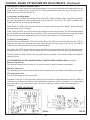
SPIN DRIVE CONTROL BOARD (SDC)
The Spin Drive Control Board has three potentiometers on the lower board and two potentiometers on the
upper board as shown on FIG. 45 and FIG. 46. These potentiometers have been set at the factory to the
positions shown on FIG. 45 and FIG. 46.
In the Relief Grinding Mode-The Relief Speed Pot (RSP) and the Relief Torque Pot (RTP) interact with each other. The (RSP) is located on
the upper spin board as a relief speed preset at 9:30 (20 Volts DC). See FIG. 45. The (RTP) is located on the
control panel and is for relief torque adjustment.
Relief Speed Pot (RSP) when rotated clockwise will increase maximum spin drive speed. This speed should
never be above the 10:30 setting.
Relief Torque Pot (RTP) can vary the reel to finger holding torque for relief grinding. The recommended starting
point is 30 in/lbs of torque setting. Never adjust the (RTP) potentiometer dial past the red line marking. Setting
the reel to finger torque to high could cause the traverse motor system to not operate smoothly.
In the Spin Grinding Mode-The Spin Torque Potentiometer (STP) and the Spin Speed Pot (SSP) interact with each other. The (STP) is
located on the upper spin board as spin torque preset at 2:00 for torque setting. See FIG. 45. The (SSP) is
located on the control panel and is for spin speed adjustment.
Spin Torque Pot (STP) controls maximum torque allowable in the spin grinding cycle only. This should never be
adjusted past the 2:30 position. If the reel does not turn check that the reel is free turning by hand spinning.
The Spin speed Pot (SSP) controls reel spin speed, adjust as required. This controls the spin drive speed for
spinning the reel.
POTENTIOMETERS ON THE LOWER BOARD OF THE SPIN DRIVE CONTROL (SDC) See FIG. 46.
Maximum Speed Pot-The maximum speed is factory preset to 4:30 (fully clockwise) to allow for maximum spin speed.
Minimum Speed Pot-The minimum speed is factory preset at 8:30 (full counterclockwise) so zero speed is obtainable for spin speed.
IR Compensation Pot-The IR Compensation is factory set at 9:00.
Regulation of the spin or relief grind spin motor may be improved by a slight adjustment of the IR COMP pot
clockwise from its factory-set position. Overcompensation causes the motor to oscillate or to increase speed
when fully loaded. If you reach such a point, turn the IR COMP pot counterclockwise until symptoms just
disappear.
UPPER SPIN BOARD
LOWER SPIN BOARD
FIG. 45
25
FIG. 46
ELECTRICAL TROUBLESHOOTING
SKILL AND TRAINING REQUIRED FOR ELECTRICAL SERVICING
This Electrical Troubleshooting section is designed for technicians who have the necessary electrical
knowledge and skills to reliably test and repair the 550 electrical system. For those without that background,
service can be arranged through your local distributor.
This section presumes that you are already familiar with the normal operation of the Grinder. If not, you
should read the front of this Manual, or do the servicing in conjunction with someone who is familiar with its
operation.
Persons without the necessary knowledge and skills should not remove the control box cover or attempt any
internal troubleshooting, adjustments, or parts replacement.
If you have any question not answered in this manual, please call your distributor. They will contact the
manufacturer if necessary.
WIRE LABELS
All wires on the 550 have a wire label at each end for troubleshooting. The wire label has a code which tells
you wiring information. The wire label has a seven position code. The first two digits are the wire number: 0199. The next three numbers or letters are the code for the component to which the wire attaches. Example:
TDC for Traverse Drive Control. The last two numbers or letters are the number of the terminal on the
component to which the wire attaches.
ELECTRICAL TROUBLESHOOTING INDEX
AC Main Power Controls ..................................................................................................... Page 27-29
Spin Drive Controls ............................................................................................................. Page 30-33
Grinding Motor Controls ....................................................................................................... Page 34-35
Traverse Drive Controls-w/prox .......................................................................................... Page 36-38
Traverse--stopping and reversing........................................................................................ Page 38-40
26
ELECTRICAL TROUBLESHOOTING (Continued)
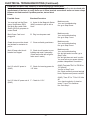
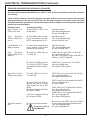
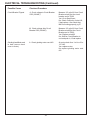
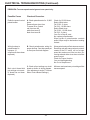
PROBLEM--AC Main Power Controls: no electrical power to control panel.
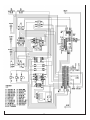
Verify all wires shown on the wiring diagram on pages 72-75 are correct and pull on wire terminals with
approximately 3 lbs force to verify there are no loose terminal connections and/or no loose crimps
between wire and terminal. If problem persists, test as listed
below.
Possible Cause
Checkout Procedure
You must pull out the Emergency Stop Button (ESS)
and push the system Start
Switch (SSS) to get power to
control Panel
A. Listen for the Magnetic Starter
(MAG) contacts to pull in with a
clunk
Machine works
Yes--end troubleshooting
No--go to Step B next
Main Power Cord is not
plugged in
B. Plug in main power cord
Machine works
Yes--end troubleshooting
No--go to Step C next
Guard doors must be closed
and latched for contactor to
pull in.
C. Close and latch guard doors.
Machine works
Yes--end troubleshooting
No--go to Step D next
Main 20 amp outlet circuit
breaker has tripped
D. Check circuit breaker in your
building and reset if necessary.
(Check wall outlet with a light to
make sure it works)
Machine works
Yes--end troubleshooting
No--but light works in outlet--go to
Step E next.
No--but light does not work in outlet.
You must solve your power delivery
problem independent of machine.
No 115 volts AC power to
(MAG)
E. Check for incoming power for
115 Volts.
(MAG) Terminals TB-01 to TB-02 for
115 Volts AC
Yes-Go to Step F next.
No--Check continuity across terminal
block, Replace main power cord #32
(MAG) Term #T1 to T3 for 115 Volts
AC
Yes--check continuity of wires between T1 and T3 to switches
No--Go to Step I
No 115 Volts AC power out of F. Check for 115 V
(MAG)
27
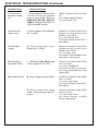
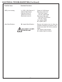
ELECTRICAL TROUBLESHOOTING (Continued)
Possible Causes
Checkout Procedure
115V power not
delivered to (MAG)
coil.
I. Check at Magnetic Starter coil for
115 Volts AC with main electrical
power on and pushing (SSS) and
GRINDING MOTOR SWITCH
(GMS) and SPIN MOTOR SWITCH
(SMS) in the OFF position.
(MAG) Term #A1 to A2 for 115 volts
AC
Yes--replace magnetic starter
No--go to Step J. next
No power to the
control circuit
J. Check voltage to Circuit Breaker
CB-1 (1 AMP)
Measure 115 volts AC from Circuit
Breaker wire #10 at the Circuit
Breaker end to TB-02.
Yes-- Go to Step K. next
No--Check continuity of wire #41, if
bad replace
Circuit Breaker
Tripped
K. Check voltage after Circuit
Breaker CB-1 (1-AMP)
Measure 115 Volts AC from Circuit
Breaker wire #11 at the Circuit
Breaker end to TB-02.
Yes--To Step L. next
No--Wait for Circuit Breaker to cool
and push in, if bad replace
Bad Emergency
Stop Switch (ESS)
L. Pull up on Stop Button and
Check voltage after the (ESS).
Measure 115 Volts AC from (ESS)
term 1 to TB-02.
Yes--Go to Step M. next
No--Check wire #03 for continuity,
then verify switch continuity. If bad
replace EES
Bad Grinding Switch
M. Check Voltage to switch (GMS)
Measure 115 Volts AC from (GMS)
term 1 to TB-02
Yes--Go to Step N next.
No--Check continuity of wire #09, if
bad replace
N. Check Voltage from switch
(GMS). Switch must be in the OFF
position.
Measure 115 Volts AC from (GMS)
term 2 to TB-02.
Yes--Go to Step O next
No--Check continuity of (GMS)
switch, if bad replace.
28
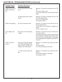
ELECTRICAL TROUBLESHOOTING (Continued)
Possible Cause
Checkout Procedure
System Start Switch
(SSS) not functioning.
O. Check push button contact
input.
Measure 115 volts AC at switch term 3 to TB02
Yes--Go to Step P. next
No--Check continuity of wire #10 from SSS to
GMS
P. Check push button contact
output.
Measure 115 Volts AC at switch term 4 to TB02 with button pressed
Yes-- Go to Step Q next
No--Replace switch
(MAG) not operating
Q. Check contactor action.
Measure 115 Volts AC at A1 and A2 on contractor with (SSS) on.
Yes--If MAG is not clicking on, replace contractor
No--Go to Step R. next.
Line Voltage is too
low
R. Check (LVR) monitoring
voltage
Measure 115 volts AC at (LVR) Term #6 to #7
Yes--go to Step S.
No--check continuity of wires to term #6 and
#7 from (MAG). If voltage is less than 101 Volts
AC check the incoming voltage. The grinder
will not operate with a voltage of less than 101
Volts AC.
(LVR) is not Functioning
S. Check (LVR) input voltage
with main electrical power on
and pushing (SSS) and
(GMS) in the OFF position.
Measure 115 volts AC from (LVR) term #8 to
TB-02
Yes--go to Step T.
No-- Check continuity of wires 56
T. Check (LVR) output voltage
Measure 115 volts AC from (LVR) term #1 to
TB-02
Yes--Check continuity of wire #58
No--Replace (LVR)
29
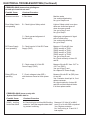
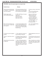
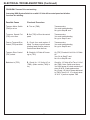
ELECTRICAL TROUBLESHOOTING (Continued)
PROBLEM--(MAG) turns on but grinding motor and spin motor do not work
Possible Cause
Checkout Procedure
Doors are not shut
A. Shut doors
Machine works
Yes--end troubleshooting
No--go to Step B next
Door Safety Switch
not operating
B. Check light on Safety switch.
Light on Safety switch is on when
doors are closed and goes off
when doors are opened
Yes--go to Step C next.
No--go to Step D
C. Check gap and alignment of
Switch to Key.
Adjust gap or alignment of signal
side of switch to key.
Yes--end trouble shooting
No--go to Step F.
D. Check input to 24 Volt DC Power
Supply (PWS)
Measure 115 volts AC from
(PWS) term #4 to TB-01,
(PWS) term #2 to TB-01,
(PWS) term #3 to TB-02,
(PWS) term #1 to TB-02.
Yes--go to Step E next.
No--Check continuity of wires 58
and 59.
E. Check output of 24 Volt DC
Power Supply (PWS)
Measure 24 volts DC from -OUT to
+OUT on (PWS).
Yes--go to Step F next
No--replace DC Power Supply
F. Check voltage at relay (REL)
with the doors closed on main power
on.
Measure 24 volts DC at (REL) term
A1 and A2
Yes--Contactor should pull in, if not
replace contactor.
No--check continuity of wires #51
and #52 and their terminal blocks.
If ok then replace switch
DC Power Supply
is not operating
Relay (REL) not
operating
PROBLEM--(MAG) turns on only with
System Start Switch held in.
Possible Cause
Checkout Procedure
(MAG) holding
contact has failed
A. Check wiring to and from MAG holding
contact in. Verify the magnetic starter holding contact is working.
30
Measure 115 Volts AC at MAG
term 13 to 14 with SSS not pushed.
Yes--Replace contactor
No--Verify wiring to 13 and 14. If
bad replace.
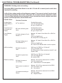
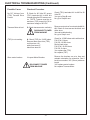
ELECTRICAL TROUBLESHOOTING (Continued)
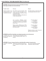
PROBLEM--SPIN DRIVE NOT WORKING IN SPIN MODE.
Assuming (SSS) System Start Switch is on with 115 volts AC to control panel and all other functions
are working.
Verify all wires shown on the wiring diagram on pages 84-87 are correct and pull on wire terminals
with approximately 3 lbs force to verify there are no loose terminal connections and/or not loose
crimps between wire and terminal. If loose terminals are found, retighten and retest system. If problem
persists, test as listed below.
Possible Cause
Spin Speed Pot
(SSP) set to zero
Checkout Procedure
A. Set (SSP) to 200 on the
control panel.
Spin
Rotation
Switch (SRS) are
not on
B. Turn (SRS) switch to direction of reel rotation required.
NOTE: center position is off
Spin Motor works
Yes--end troubleshooting
No--go to Step C. next
Circuit Breaker 2 (4
AMP) is tripped
C. Check Circuit breaker and
reset, replace if bad Check
that reel is free spinning.
Spin Motor works
Yes--end troubleshooting
No--go to Step D. next
Spin
Rotation
Switch (SRS) is not
working
D. Check for (SRS) input of
115 Volts AC
(SRS) Term 5 to term 8 for 115 Volts AC
Yes--go to Step E. next
No--Verify DC power Supply and REL is
working. - See D-F PAge 30.
E. Check for (SRS) output of
115 Volts AC NOTE: Check
spin rotation switch in both positions.
(SRS) Term 1 to term 4 for 115 Volts AC
Yes--go to Step F. next
No--replace (SRS) switch
F. Check (SDC) L1 to L2 for
115 Volts AC
(SDC) Term L1 to term L2 for 115 volts AC
Yes--go to Step G. next
No--replace wires 06 and 07.
Spin Drive Control
(SDS) is not working
G. Check (SDC) A1 & A2 for
approx. 90 Volts DC (Have
Spin Speed Pot set to 400
RPM)
H. Check for approx 90 Volts
DC input to (SRS)
J. Check for approx 90 Volts
DC out put to (SRS).
Spin Drive motor is
bad
K. Check spin motor continuity
Disconnect Power
from Machine!
31
Spin Motor works
Yes--end troubleshooting
No--go to Step B next
(SDC) Term A1 to A2 for approx 90 volts DC
Yes--go to Step H. next
No--go to Step L.
(SRS) Term 6 to 7 for approx 90 Volts DC
Yes--go to Step J. next
No--replace wires 02 & 09
(SRS) Term 2 to 3 for approx 90 Volts DC
Yes--go to Step K. next
No--replace (SRS) switch
Remove wires at (SRS) Term 2 & 3 check
0 ohms across the black and white wires
Yes--end troubleshooting
No--got to Step M. next
ELECTRICAL TROUBLESHOOTING (Continued)
Possible Cause
Checkout Procedure
(SSP) is not working
L. (SSP) (10K) Remove 3
Remote Speed wires.
Red wire to term W
White wire to term L
Black wire to term H
Check for 10,000 ohms
Red wire to white wire
Full CCW--0 ohms
Full CW-10,000 ohms
Red wire to black wire
Full CCW--10,000 ohms
Full CW--0 ohms
Yes--replace (SDC)
No--replace (SSP)
Worn Motor Brushes
M. Inspect Motor Brushes
Remove the brushes one at a time and
maintain orientation for reinsertion. See if
brush is worn short 3/8" (10 mm) minimum
length.
Yes--replace motor brushes
No--replace Spin Drive Motor
DISCONNECT POWER
FROM MACHINE !
32
ELECTRICAL TROUBLESHOOTING (Continued)
SPIN DRIVE
PROBLEM : Spin drive speed goes at one speed only.
Possible Cause
Remedy
Wiring hookup to potentiometer
is improper. (If components
have been replaced
A. Check potentiometer wiring for
proper hookup. See that speed
pot is wired per electrical diagram
If wiring is wrong, correct and
test.
Yes--end of troubleshooting
No--Go to Step B. next
Defective spin speed
control (SSP) potentiometer.
B. (SSP) 10K Remove 3 remote
speed wires.
red wire to term W
white wire to term L
black wire to term H
Check for 10,000 ohms
Red wire to white wire
Full CCW--0 ohms
Full CW--10,000 ohms
Red wire to black wire
Full CCW--10,000 ohms
Full CW--0 ohms
Yes-- Go to Step C. next
No--Replace (SSP)
Main circuit board dial pot settings not correct. (If board has
been replaced
C. Check all pot settings on both
boards as of the (SDC) shown on
Page 24. (See Adjustment Section Spin Drive Control [SDC]
Board Setting).
Yes-- end of troubleshooting
No--replace (SDC)
IR Comp trim pot not adjusted
properly.
A. See adjustment section for
trim pot setting on Page 24.
Original adjustment was not set
properly
Torque to rotate the reel too
high.
B. Readjust bearing preload for
the reel. Maximum torque load 25
in./lb to rotate reel.
Too much load on drive motor will
cause motor to hunt and vary
speed.
Check all terminal connections
for tightness.
C. When .250 female spade terminals are not tight, remove and
crimp slightly together. When reinstalling, push on pressure
should have increased for good
contact.
When connections are not tight
the control board varies voltage
to the DC motor which then varies speed.
33
ELECTRICAL TROUBLESHOOTING (Continued)
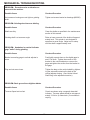
PROBLEM-- Grinding motor not working.
Assuming (SSS) System Start Switch is on with 115 volts AC to control panel and all other
functions are working.
Verify all wires shown on the wiring diagram on pages 70 are correct and pull on wire terminals with approximately 3lbs force to verify there are no loose terminal connections and/or
no loose crimps between wire and terminal. If loose terminals are found, retighten and retest
system. If problem persists, test as listed below.
Possible Cause
Checkout Procedure
Grinding Motor
Switch (GMS) is
not on
A. Turn switch on
Grinding Motor works
Yes--end troubleshooting
No--go to Step B. next
Guard doors are
not closed and
latched
B. Close and latch guard
doors.
Grinding Motor works
Yes--end troubleshooting
No--go to Step C. next
Circiut Breaker
Tripped
C. Check voltage to Circuit
Breaker - 2.
Measure 115 Volts AC from Wire #15 on CB-02 to
TB-02.
Yes--go to Step D. next
No--Verify REL is working- pg. 30
D. Check Voltage out of
Circuit Breaker- 2
Measure 115 Volts AC from Wire #15 on CB-02 to
TB-02.
Yes--go to Step E. next
No-- Reset circuit Breaker after it cools or replace.
E. Check for power to
GMS
GMS term 5 to TB-02 for 115 Volts AC
Yes--go to Step F. next
No--With power off, check continuity of wire 53 and
replace if bad.
F. Check for power from
GMS
GMS Term 4 to TB-02 for 115 Volts AC
Yes--Go to Step G. next
No--replace GMS
G. Check for power at
coil of Relay
Measure 115V AC from terminals 0 to 1 of REL2
Yes--Go to step H. next
No -- Check wires 57 & 01 and replace
H. No power to contacts of
relay.
Measure 115V AC from terminals 4 to 8 of REL2
Yes--Go to step I. next
No -- Go to step J,
I. Contacts not working in
Relay 2
Measure 115V AC from terminals 2 to 6 of REL2
Yes--Go to step L
No -- Replace Relay 2
GMS not working
RELAY not working
34
ELECTRICAL TROUBLESHOOTING (Continued)
Possible Cause
Checkout Procedure
Circuit Breaker Tripped
J. Check voltage to Circuit Breaker
CB-3 (20 AMP)
Measure 115 volts AC from Circuit
Breaker wire #16 at the circuit
breaker end to TB-02
Yes--Go to Step K next
No--Check Continuity of wire #16,
if bad replace. Also check that
MAG is working properly. pg 27
K. Check voltage after Circuit
Breaker CB-3 (20 AMP)
Measure 115 volts AC from Circuit
Breaker wire #03 at the Circuit
Breaker end to TB-02.
Yes--Replace wire #03
No--Wait for Circuit Breaker to
cool and push in, if bad replace
L. Check grinding motor cord #01.
At motor check Line 1 to Line 2 for
115 V AC
Yes--replace motor
No--replace grinding motor cord
#31
Grinding Head Motor cord
is bad (remove back
cover to motor)
35
ELECTRICAL TROUBLESHOOTING (Continued)
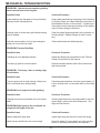
PROBLEM--Traverse Drive not working.
Assuming (SSS) System Switch is on with 115 Volts AC to control panel and all other
functions are working.
Possible Cause
Checkout Procedure
Traverse Motor Switch
(TMS) is not on
A. Turn on (TMS)
Traverse works
Yes--end troubleshooting
No--got to Step B. next
Traverse Speed Pot
(TSP) set to zero
B. Set (TSP) to 35 on the control
panel
Traverse works
Yes--end troubleshooting
No--go to Step C. next
Fuse on Traverse Drive
Control (TDC) has failed
C. Check fuse and replace if
failed. Too heavy a grind causes
grinding head traverse motor to
overload and blow the fuse,
Traverse works
Yes--end troubleshooting
No--go to Step D. next
Traverse Drive Control
(TDC) is bad
D. Check for 115 Volts AC incoming to (TDC)
On (TDC) Terminal L1 to L2 for 115 Volts
AC
Yes--Go to Step F. next
No--Go to Step E. next
Bad wires to (TDC)
E. Check for 115 Volts AC at
(TMS). (Make certain (TMS) is
on)
Check for 115 Volts AC at Term 1 & 4 of
the (TMS) Note: Switch must be on.
Yes--With power off, check continuity of
wires 28 & 29, if bad replace wires.
No--Check 115 Volt AC power delivered
to (TMS) Term 2 & 5. If no check wires
12 & 13. If yes then replace TMS
36
ELECTRICAL TROUBLESHOOTING (Continued)
Possible Cause
Checkout Procedure
No DC Voltage from
(TDC) Traverse Drive
Control
F. Check for 90 Volts DC across
(TDC) terminals #A1 to #A2 this
voltage drives the DC traverse motor. NOTE: Traverse must be on
and have (TSP) turned full CW to
maximum voltage of 90 VDC
Check (TDC) terminals #A1 to #A2 for 90
Volts DC
Yes--go to Step G. next
No--go to Step H. next
Traverse Motor is bad
G. Check traverse motor continuity
Remove motor wires from terminals #A1 &
#A2 Check 0 ohms across the black and
white wires
Yes-end troubleshooting
No--go to Step I. next
DISCONNECT POWER
FROM MACHINE
(TSP) is not working
H. Check (TSP) for 10,000 ohms.
Remove three wires from (TDC)
red from term #8
white from term #7
black from term #9
Check for 10,000 ohms red to white wires
Full CCW--0 ohms
Full CW--10,000 ohms
Red to black wires
Full CCW--10,000 ohms
Full CW--0 ohms
Yes--replace the (TDC)
No--replace (TSP)
Worn motor brushes
I. Inspect Motor Brushes
Remove the brushes one at a time and
maintain orientation for reinsertion. See if
brush is worn short, 3/8" (10 mm) minimum
length.
Yes--replace motor brushes
No--replace Traverse Motor
DISCONNECT POWER
FROM MACHINE
37
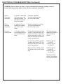
ELECTRICAL TROUBLESHOOTING (Continued)
PROBLEM--Traverse does not stop to reverse directions when bearing housing comes in
contact with the proximity switch on the left side or right side of machine.
Prox is
Positioned
Incorrectly
A. Check to make sure
the Proxes are on the
appropriate sides. The
light side Prox should
be on the outside
If incorrect, reposition
Yes--end troubleshooting
No--Go to Step B next.
Prox is
mounted
incorrectly
B. Adjust so Prox is
located with sensing
end out from prox
holder
Adjust Prox depth on mounting
Yes--end troubleshooting
No--Go to Step C next.
Proximity
Switch is bad.
C. Proximity switch is
not working properly or
wire connections are
loose.
First check to see if proximity light
comes on. When the light is on, it
means that there is electricity
coming to proximity switch. Actuate prox switches with steel tool
to take measurements.
The light coming on
shows the proximity is
getting electrical
contact.
Left proximity (PROX 1) check
Traverse drive Control (TDC) between terminals #13 (black wire)
and #15 (brown wire).
Proximity light on0 Volts DC
Proximity light off12 Volts DC
Right proximity (PROX) check
#13 (black wire) and #15 (brown
wire).
Proximity light on0 Volts DC
Proximity light off12 Volts DC
Replace proximity
switch if the voltages
do not read as above.
38
ELECTRICAL TROUBLESHOOTING (Continued)
PROBLEM--Traverse speed control goes at one speed only.
Possible Cause
Checkout Procedure
Defective speed control
potentiometer
A. Check potentiometer for 10,000
ohms.
Remove three wires from
Traverse Drive Control
red from term #8
white from term #7
black from term #9
Check for 10,000 ohms
Red to White wires
Full CCW - 0 ohms
Full CW - 10,000 ohms
Red to Black wires
Full CCW - 10,000 ohms
Full CW - 0 ohms
Yes--Go to Step C. next
No--replace potentiometer.
Wiper inside of potentiometer controls
speed. Wiper may be bad and not making
contact.
Wiring hookup to
potentiometer is
improper. (If
components have been
replaced.)
B. Check potentiometer wiring for
proper hookup. See that speed pot
is wired per electrical diagram
Wrong wire hookup effects traverse control.
Reversing red and orange wires to potentiometer to the D C motor will run at zero
speed but maximum will be too slow. Reversing red and white wires does not affect
speed control.
Check for Proper function.
Yes--end troubleshooting
No--Go to Step D. next
C. Check all pot settings on circuit
board as shown in wiring diagram.
(See adjustment section Traverse
Motor Control Board Settings.)
Minimum and maximum pot settings effect
traverse speed.
Main circuit board dial
pot settings not correct.
(If board has not been
replaced.)
39
ELECTRICAL TROUBLESHOOTING (Continued)
PROBLEM--If the wheel traverses to one end of stroke or the other
and it stops and does not reverse direction.
Possible Cause
Remedy
Reason
Proximity switch is not
working properly or wire
connections are loose
First check to see of proximity light
comes on. When the light is on, it
means that there is electricity coming
to proximity switch.
Actuate prox switches with steel tool
to take measurements.
The light coming on shows the proximity is getting electrical contact.
Left proximity (PROX1) check
Traverse drive Control (TDC) between
terminals #14 (black wire) and #15
(brown wire).
Proximity light on0 Volts DC
Proximity light off12 Volts DC
Right proximity (PROX) check (TDC)
between terminals #13 (black wire) and
#15 (brown wire).
Proximity light on0 Volts DC
Proximity light off12 Volts DC
Replace proximity switch if the voltages do not read as above.
PROBLEM--Insufficient hesitation at carriage stops prior to reversing traverse.
The dwell time on the
traverse drive control not
set properly.
Reset dwell time as required. One increment increases Dwell time by 1/2
second.
PROBLEM--Traverse changes directions erratically while running in traverse cycle.
A loose wire connection will give
Loose wire to proximity Check wire connections from the proxintermittent electrical contact.
switch.
imity switches and tighten down
screws.
40
41
MECHANICAL TROUBLESHOOTING
PROBLEM-- Excessice noise or vibration on
one end of the machine.
Possible Cause
Checkout Procedure
Set screws on bearings are not tight on grinding
shaft.
Tighten set screws located on bearings (#80336)
PROBLEM--Grinding wheel traverse binding.
Possible Cause
Checkout Procedure
Shafts are dirty.
Clean the shafts as specified in the maintenance
section of this manual.
Grinding shaft is at a severe angle.
Raise or lower one end of the shaft until approximately level. This grinder is not designed to
operate at a sever angle. Adjust reel or setup
until the shaft is approximately level.
PROBLEM-- Handwheel or vertical indicator
gage "walks" during grinding.
Possible Cause
Checkout Procedure
Bracket connecting gage to vertical adjuster is
loose.
Push lightly up and down on the digital gage to
see if it is loose. Tighten the screws on the
bracket to the vertical adjuster or remove the
gage and tighten the screws from the bracket to
the gage.
Plug and set screw loose.
Tighten the drag on the vertical shafts by tightening the setscrew located on the back of the
vertical adjuster husing. (See Vertical Infeed
Shaft Drag in the adjustment section.)
PROBLEM--Reels ground have high/low blades
Possible Cause
Checkout Procedure
Traverse Speed set too fast.
Check roundness using a magnetic base dial
indicator. Traverse speed should be set approximately 12 ft/min. (4 meters/min.) if roundness is
varying.
42
MECHANICAL TROUBLESHOOTING
PROBLEM-- Uneven traverse speed or grinding
stock removal from reel is irregular.
Possible Cause
Checkout Procedure
Linear bearings are damaged or have grit buildup
causing uneven traversing load.
Clean shafts and bearings according to the lubrication
of Grinding Shaft and Linear Bearings instructions in
the Maintance Section of the manual. If problem persists replace linear bearings according to the replacement of linear bearings instructions.
Grinding shaft or wheels have grit buildup causing
uneven loading.
Clean the wheel flanges and shaft (see Lubrication of
Grinding Shaft). Replace flanges or shaft if necessary.
Left side traverse pulley is full of grit causing the
pulley not to turn freely on shaft.
Clean and lubricate the shaft and pulley.
PROBLEM--Traverse Belt Slips
Possible Cause
Checkout Procedure
Clamping tip is not adjusted properly.
Adjust the clamping tip as specified in the Traverse
Clamp Force section of this manual.
Too heavy a grind for traverse speed.
Slow the traverse speed or back off on the amount
that is being infed.
PROBLEM-- Too heavy a burr on cutting edge
of reel blades.
Possible Cause
Checkout Procedure
Traverse speed set too high causing a heavy burr
on the reel blade when spin grinding.
Traverse speed should be set lower approximately 12
ft./min (4 meters/min.) for a smaller burr on the cutting
edge.
PROBLEM--Cone shaped reel after grinding.
Possible Cause
Checkout Procedure
Grinding head travel not parallel to the reel center
shaft.
Grinding head travel was not setup parallel to the reel
center shaft in vertical and horizontal planes. See
Align the Reel Section.
PROBLEM--Relief grind on the reel blades do
not go the full length of the reel.
Possible Cause
Checkout Procedure
Need to adjust the finger stop.
Adjust finger stop and check for contact full length.
Need to dress the Wheel to the correct angle
Dress the wheel (For more detail, see relief grinding
section in operating instructions of the manual.)
43
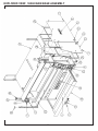
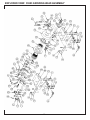
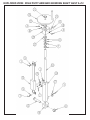
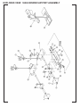
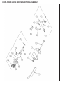
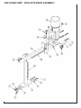
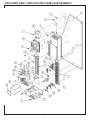
EXPLODED VIEW: 55568 MAIN BASE ASSEMBLY
44
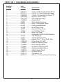
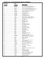
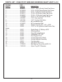
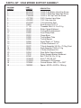
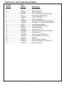
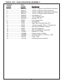
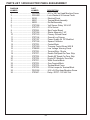
PARTS LIST: 55568 MAIN BASE ASSEMBLY
DIAGRAM
NUMBER
PART
NUMBER
DESCRIPTION
1 ................................. B191011 ............10-24 x 5/8 Socket Head Cap Screw
2 ................................. B371611 ............3/8-16 x 1 Socket Head Cap Screw
3 ................................. D250808 ............1/4-20 x 1/2 threaded Cut Screw "F"
4 ................................. H251202 ........... Roll Pin .25 d x .75 Lg
6 ................................. K371501 ........... 3/8 Lockwasher Split
7 ................................. 3708697............Patent Decal
8 ................................. 09891 ................Grab Handle Enclosure
9 ................................. 09913 ................Neary Technologies Decal
10 ............................... 50234 ................Tooling Bar-Machined
11 ............................... 50306 ................Drive Panel Cover
12 ............................... 50307 ................Electrical Panel Cover
13 ............................... 55129 ................Control Panel Decal
14 ............................... 50398 ................Neary 550 Decal
15 ........................................................... Nameplate 550SR & Serial Number
16 ............................... 55513 ................Tray Weldment
17 ............................... 55100 ................Frame Weldment 550
18 ............................... 80362 ................Square Plug 1" Sq x 14 Ga Tube
20 ............................... 3708378............Foam Strip .25T 50Ft
21 ............................... 3708448 ............Electrical Warning Decal
22 ............................... 3708458 ............Sharp Warning Decal
23 ............................... 3708605 ............Respirator Warning Decal
24 ............................... 3708606 ............Hearing Protection Decal
25 ............................... 3708703 ............Safety Symbol Decal
26 ............................... 6309111 ............Up/Down Decal
27 ............................... K370101 ............Flat Washer 3/8
28 ............................... B372011 ............3/8-16 x 1.25 Socket Head Cap Screw
45
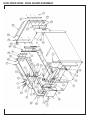
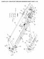
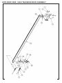
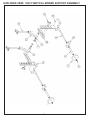
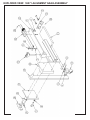
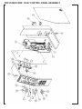
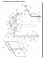
EXPLODED VIEW: 55586 GUARD ASSEMBLY
46
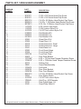
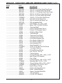
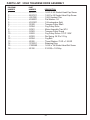
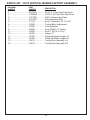
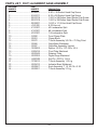
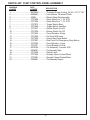
PARTS LIST: 55586 GUARD ASSEMBLY
DIAGRAM
NUMBER
PART
NUMBER
DESCRIPTION
1 .................................... B191011 .............. 10-24 x 5/8 Socket Head Cap Screw
2 .................................... B191211 .............. 10-24 x 3/4 Socket Head Cap Screw
3 .................................... B251216 .............. 1/4-20 x 3/4 Button Head Socket Cap Screw
4 .................................... B252416 .............. 1/4-20 x 1-1/2 Button Head Socket Cap Screw
5 .................................... B310813 .............. 5/16-18 x 1/2 Button Head Socket Cap Screw
6 .................................... J167000 .............. 8-32 Locknut Jam Nylon
7 .................................... J197000 .............. 10-24 Locknut Nylon Full
8 .................................... J257000 .............. 1/4-20 Thin Locknut Nylon Full
9 .................................... K190001 .............. Flat Washer #10
10 .................................. K250001 .............. Flat Washer 1/4
11 .................................. K310001 .............. Flat Washer 5/16
12 .................................. 50366 .................. Guard Door R.H.
13 .................................. 50368 .................. Guard Door L.H.
14 .................................. 50370 .................. Guard Panel R.H. Small
15 .................................. 50372 .................. Guard Panel R.H. Large
16 .................................. 55143 ................... Guard Panel L.H.
17 .................................. 50382 .................. Front Guard Hinge
18 .................................. 50384 .................. Front Hinge Plate
19 .................................. 6309124 .............. Front Door Plate
20 .................................. 50402 .................. Door Rear Bracket
21 .................................. 3707585* ............. 8-32 x .75 Flat Head Tamper Resistant Screw
22 .................................. 3708819* ............. 8-32 x .75 Button Head Tamper Resistant Screw
23 .................................. 80374 .................. Rubber Pad
24 .................................. 55585 ................... Guard Plate Assembly
25 .................................. 3708416 .............. Soft Latch
26 .................................. 6309033 .............. Door Rear Bracket
27 .................................. 6309038 .............. Door Front Bracket
28 .................................. B251016 .............. 1/4-20 x 5/8 Button Head Socket Cap Screw
29 .................................. 55523 .................. Door Safety Switch
30 .................................. J257000 .............. 1/4-20 Thin Locknut Nylon
31 .................................. 3708542 ............... Hole Plug - .625 Diameter
32 .................................. 55139 ................... Rear Guard Hinge - LH
33 .................................. 55140 ................... Guard Plate- Rear LH
* A special wrench is need to adjust these screws. Please contact the factory for details.
47
EXPLODED VIEW: 55583 GRINDING HEAD ASSEMBLY
48
PARTS LIST: 55583 GRINDING HEAED ASSEMBLY
DIAGRAM
NUMBER
PART
NUMBER
DESCRIPTION
1 ...................................................... B191011 .......................... 10-24 X 5/8 Socket Head Cap Screw
2 ...................................................... 3708848 .......................... 1/4-28 x 1/2 Socket Head Cap Screw w/ patch
3 ...................................................... B251211 .......................... 1/4-20 x 3/4 Socket Head Cap Screw
4 ...................................................... B250816 ......................... 1/4-20 x 1/2 Button Head Socket Cap Screw
5 ...................................................... 80407 .............................. 1/4-20 x 1.00 Socket HeadCap Screw - Low Head
6 ...................................................... B251216 ......................... 1/4-20 x 3/4 Button Head Socket Cap Screw
7 ...................................................... B253211 .......................... 1/4-20 x 2.00 Socket Head Cap Screw
8 ...................................................... H250602 ......................... Roll Pin .25D x .375 Lg
9 ...................................................... J252000 .......................... 1/4-20 Hex Jam Nut
10 .................................................... J627200 .......................... 5/8-18 Locknut Jam Nylon
12 .................................................... K250001 ......................... Flat Washer 1/4
13 .................................................... K251501 ......................... 1/4 Lockwasher Split
14 .................................................... J257000 .......................... 1/4-20 Locknut Jam Nylon
15 .................................................... 05720 .............................. Grinding Wheel 6 x 2.75B x 1.5W 46G
16 .................................................... 05731 .............................. Grinding Wheel 6 x 2.75B x .38W 24G Type 1
17 .................................................... 3708839 .......................... 3/8-16 x 1/2 Screw w/locking Flange
18 .................................................... 50037 .............................. Spin Flange Nut
19 .................................................... 50039 .............................. Spin Wheel Flange
20 .................................................... 50073 .............................. Wear Pad
21 .................................................... 55200 .............................. Relief Wheel Flange
22 .................................................... 55201 .............................. Relief Flange Nut
23 .................................................... 50204 .............................. Spin Yoke
24 .................................................... 55126 .............................. Bearing Support Bracket
25 .................................................... 55280 .............................. Double Bearing Assembly
26 .................................................... 80406 .............................. Spacer washer
27 .................................................... 50297 .............................. Traverse Shoe
28 .................................................... 50298 .............................. Traverse Clamp Bracket
29 .................................................... 55296 .............................. Single Bearing Assembly
30 .................................................... 50310 .............................. Belt Clamp Tip
31 .................................................... 50320 .............................. Traverse Guard
32 .................................................... 50321 .............................. Shield Mount Bracket
33 .................................................... 50324 .............................. Spark Shield
34 .................................................... 50329 .............................. Spin Support
35 .................................................... 50569 .............................. Bearing Housing Assembly
36 .................................................... 09404 .............................. Linear Bearing
37 .................................................... 09479 .............................. Oil Seal 1"ID x 1.57"OD x .187
38 .................................................... 3708561 .......................... Adjustable Handle 3/8-16 x 1.56 Long
39 .................................................... 3708835 .......................... Adjustable Handle 1/4-20 x 1.25 Long
40 .................................................... 27115 .............................. Spacer - .386 ID x .50 OD x .75 Long
41 .................................................... 80335 .............................. Destaco 602 Clamp
42 .................................................... 80337 .............................. T-knob Assembly
43 .................................................... xxxxxx ............................... Washer
44 .................................................... B190811 .......................... 10-24 x 1/2 Socket Head Cap Screw
45 .................................................... 55119 .............................. Finger Rotate Base
46 .................................................... 6009057 .......................... Spacer .265 ID x .48 OD x .50 Long
47 .................................................... 55144 .............................. Knob - 1/4-20 x 1" Diameter
........................................................ C190360 ......................... 10-32 x 3/16 Socket Head Set Screw
48 .................................................... 3708838 .......................... Star Knob - 1" Diameter
49 .................................................... 55112 .............................. Cam Plate
50 .................................................... 80392 .............................. Cam Follower - 1/2" Diameter
51 .................................................... 55113 .............................. Finger Slide
52 .................................................... 55117 .............................. Fixed Finger
53 .................................................... B190634 ......................... 10-32 x 3/8" Button Head Socket Cap Screw
54 .................................................... 55118 .............................. Stop Pin
55 .................................................... 55116 .............................. Index Finger Stop Block
56 .................................................... H181202 ......................... 3/16 x 3/4" long Roll Pin
57 .................................................... 55579 .............................. Locking Plate Weldment
58 .................................................... 3708833 .......................... Spacer - .252 ID x .50 OD x .125 Long
59 .................................................... C190467 ......................... 10-32 x 1/4" Socket Head Set screw
60 .................................................... 55127 .............................. 3/16 Diameter Index Stop Pin
61 .................................................... 55581 .............................. Indexing Finger Assembly
62 .................................................... 3708107 .......................... Compression Spring
49
PARTS LIST: 55562 PIVOT ARM AND GRINDING SHAFT ASSY 1 of 2
50
PARTS LIST: 55562 PIVOT ARM AND GRINDING SHAFT ASSY 1 of 2
DIAGRAM
NUMBER
PART
NUMBER
DESCRIPTION
1 .................................... B313601 .............. 5/16-18 x 2-1/4 Hex Head Cap Screw
2 .................................... B371611 .............. 3/8-16 x 1 Socket Head Cap Screw
3 .................................... B372411 .............. 3/8-16 x 1-1/2 Socket Head Cap Screw
4 .................................... B373601 .............. 3/8-16 x 2-1/4 Hex Head Cap Screw
5 .................................... B752001 .............. 3/4-10 x 1.25 Hex Head Cap Screw
6 .................................... C250820 .............. 1/4-20 x 1/2 Cup Point Set Screw
7 .................................... J317100 .............. 5/16-18 Locknut Nylon Full
8 .................................... J377100 .............. 3/8-16 Locknut Hex Nylok Full
9 .................................... K371501 .............. 3/8 Lockwasher Split
10 .................................. R000453 .............. Flat Washer .31 x .88 x .104T
11 .................................. 09393 .................. Motor 1HP 115/230V 60/50Hz
12 .................................. 50235 .................. Traverse Shaft
13 .................................. 50236 .................. Pulley 2.45 Diameter Poly V
14 .................................. 50237 .................. Pulley 3.72 Diameter Poly V
15 .................................. 50256 .................. Grinding Wheel Shaft
16 .................................. 50279 .................. Tensioner Bar
17 .................................. 50280 .................. Tensioner Pivot Shaft
18 .................................. 50281 .................. Tensioner Pulley Shaft
19 .................................. 50282 .................. Pivot Shaft Support Arm
20 .................................. 50311 .................. Prox Switch Holder R.H.
21 .................................. 50318 .................. Prox Switch Holder L.H.
22 .................................. 50574 .................. Arm Assembly R.H.
23 .................................. 50576 .................. Arm Assembly L.H.
24 .................................. C190420 .............. 10-24 x 1/4 Cup Point Set Screw
25 .................................. 09680 .................. Torrington Bearing
26 .................................. 80336 .................. Piloted Bearing Flange
27 .................................. 80338 .................. Key .25 sq x 1.25 Lg
28 .................................. 80342 .................. Torsion Spring
29 .................................. 80343 .................. Conical Washer .539 x .862 x .014T
30 .................................. 80349 .................. Idler Pulley 4.0 Diameter
31 .................................. 80350 .................. Poly V Belt
32 .................................. 80351 .................. Conical Washer 1.40 x 2.03 x .024T
33 .................................. 3708425 .............. Shoulder Bolt .313 D x .375 L
34 .................................. 3709019 .............. Thrust Washer .500 x .937 x .032 T
35 .................................. 3709886 ............... Flat Washer .812 x 2.25 x.135 T
36 .................................. 80126 ................... Key 3/10 sq x 1.00 Lg
37 .................................. 55262 ................... Guard - Grinding Wheel LH
38 .................................. 3708458 ............... Decal - Warning Sharp
39 .................................. 55263 ................... Guard - Grinding Wheel RH
40 .................................. K251501 ............... 1/4 Lockwasher
41 .................................. B250816 ............... 1/4 -20 x 1/2 L BHSCS
51
EXPLODED VIEW: 55562 PIVOT ARM AND GRINDING SHAFT ASSY 2 of 2
52
PARTS LIST: 55562 PIVOT ARM AND GRINDING SHAFT ASSY 2 of 2
DIAGRAM
NUMBER
PART
NUMBER
DESCRIPTION
1 .................................... B120311 .............. 5-40 X .188 Lg Socket Head Cap Screw
2 .................................... B130605 .............. 6-32 x 3/8 Flat Head Socket Cap Screw
3 .................................... B160411 .............. 8-32 x 1/4 Socket Head Cap Screw
4 .................................... B190611 .............. 10-24 x 3/8 Socket Head Cap Screw
5 .................................... B190831 .............. 10-24 x 1/2 Socket Head Cap Screw
6 .................................... C370820 .............. 3/8-16 x 1/2 Cup Point Set Screw
7 .................................... J502000 .............. 1/2-13 Hex Jam Nut
8 .................................... J507100 .............. 1/2-13 Locknut Full Nylon
9 .................................... K161501 .............. #8 Lockwasher Split
10 .................................. K191501 .............. #10 Lockwasher Split
11 .................................. 09068 .................. Washer Conical .50 x 1.25 x .078T
12 .................................. 09299 .................. 1/2-13 x 2.5 Lg Button Head Socket Cap
Screw
13 .................................. 09707 .................. Digital Scale, 6" Mitutoyo #572
14 .................................. 50095 .................. Mounting Block
15 .................................. 50283 .................. Gage Mounting Bracket
16 .................................. 50322 .................. Handwheel 1/2-13 ID
17 .................................. 50325 .................. Arm Support Pivot
18 .................................. 50348 .................. Vertical Adjustment Shaft
19 .................................. 50573 .................. Vertical Adjuster Assembly
20 .................................. 50591 .................. Cap Assembly
21 .................................. 80344 .................. Hex Acorn Nut 1/2-13
22 .................................. 3709042 .............. Ball Bearing Thrust Nice #603-1/4
23 .................................. 7469149 .............. Nylon Plug 5/16 Diameter
53
EXPLODED VIEW: 55563 TRAVERSE DRIVE ASSEMBLY
54
PARTS LIST: 55563 TRAVERSE DRIVE ASSEMBLY
DIAGRAM
NUMBER
PART
NUMBER
DESCRIPTION
1 .................................... B251011 .............. 1/4-20 X 5/8 Socket Head Cap Screw
2 .................................... B257211 .............. 1/4-20 x 4.5 Socket Head Cap Screw
3 .................................... J257000 .............. 1/4-20 Locknut Thin
4 .................................... K250001 .............. Flat Washer 1/4
5 .................................... K251501 .............. 1/4 Lockwasher Split
6 .................................... 50309 .................. Traverse Pulley Shaft
7 .................................... 50354 .................. Cog Pulley Drive
8 .................................... 50361 .................. Motor Assembly Trav W16
9 .................................... 50363 .................. Traverse Pulley Guard
10 .................................. 55553 .................. Cog Pulley Driven .375 P .50W
11 .................................. 80353 .................. Die Spring .34 ID x 2.0 Lg
12 .................................. 80354 .................. Cog Belt
13 .................................. 80355 .................. Thrust Washer .75 ID x 1.25 OD
14 .................................. 3709331 .............. Retaining Ring
15 .................................. C250460 .............. 1/4-28 x 1/4 Socket Head Set Screw
16 .................................. 80126 .................. 3/16 SQ x 1.00 Key
55
EXPLODED VIEW: 55565 MOWER SUPPORT ASSEMBLY
56
PARTS LIST: 55565 MOWER SUPPORT ASSEMBLY
DIAGRAM
NUMBER
PART
NUMBER
DESCRIPTION
1 .................................... B251016 .............. 1/4-20 X 5/8 Button Head Cap Screw
2 .................................... B251216 .............. 1/4-20 x 3/4 Button Head Cap Screw
3 .................................... C250420 .............. 1/4-20 x 1/4 Cup Point Set Screw
4 .................................... J377000 .............. 3/8-16 Locknut Jam Nylon
5 .................................... J502000 .............. 1/2-13 Hex Jam Nut
6 .................................... K251501 .............. 1/4 Lockwasher Split
7 .................................... 09853 .................. Knob 4 prong 1/2-13 F
8 .................................... 17119 .................. Threaded Stud 1/2-13 x 65 Lg
9 .................................... 50242 .................. Roller Clamp Weldment
10 .................................. 50288 .................. Tooling Block Adjustment
11 .................................. 50290 .................. Front Clamp Plate
12 .................................. 50291 .................. Clamp Block
13 .................................. 50292 .................. Tooling Base Plate
14 .................................. 50295 .................. Tooling Spacer
15 .................................. 50296 .................. Acme Shaft L.H. Tooling
16 .................................. 50568 .................. V Roller Weldment L.H.
17 .................................. 50570 .................. T-Knob Assembly 3/8-16 x .75 Dog Point
18 .................................. 80396 ................... Knob Assembly 1/4-20 x 1.0 Lg
19 .................................. 55506 .................. V Roller Weldment R.H.
20 .................................. 50254 .................. Rear Roller Clamp Assembly
21 .................................. 70512 .................. Roller Support Bracket Weldment
22 .................................. 80346 .................. Bolt T Slot 3/8-16 x 2.0 Lg
23 .................................. 3708245 .............. Knob T 235 3/8-16 F
24 .................................. 3708393 .............. Handwheel 3.50 Diameter
25 .................................. 3709062 ............... Conical Washer .382 x .75 x .035 T
26 .................................. 3889045 ............... Spacer .406 ID x .88 OD x .38Long
57
EXPLODED VIEW: 55572 VERTICAL MOWER SUPPORT ASSEMBLY
58
PARTS LIST: 55572 VERTICAL MOWER SUPPORT ASSEMBLY
DIAGRAM
NUMBER
PART
NUMBER
DESCRIPTION
1 .................................... B371601 .............. 3/8-16 X 1 Hex Head Cap Screw
2 .................................... C250420 .............. 1/4-20 x 1/4 Cup Point Cap Screw
3 .................................... J377000 .............. 3/8-16 Locknut Jam Nylon
4 .................................... K371501 .............. 3/8 Lockwasher Split
5 .................................... 17519 .................. Knob T Assembly 1/2-13 x 6.5"
6 .................................... 50288 .................. Tooling Block Adjustment
7 .................................... 50295 .................. Tooling Spacer
8 .................................... 50296 .................. Acme Shaft L.H. Tooling
9 .................................... 50592 .................. Knob T 3/8-16 x 1.0 Lg
10 .................................. 55282 .................. Hanger "V"
11 .................................. 55343 .................. Clamp Weldment Large L.H.
12 .................................. 55358 .................. Clamp Weldment Large R.H.
13 .................................. 55511 .................. Tooling Post Assembly L.H.
14 .................................. 55512 .................. Tooling Post Assembly R.H.
59
EXPLODED VIEW: 55574 CARTON ASSEMBLY
60
PARTS LIST: 55574 CARTON ASSEMBLY
DIAGRAM
NUMBER
PART
NUMBER
DESCRIPTION
1 .................................... J377100 ............... 3/8-16 Locknut
2 .................................... 50014 .................. Spanner Wrench
3 .................................... k370001 ............... 3/8 Flat Washer
4 .................................... B378001 ............... 3/8-16 x 5.00 Hex Head Cap Screw
5 .................................... 55124 ................... Rear Roller Raised Support
6 .................................... H250802 ............... 1/4" x 1/2" Roll Pin
7 .................................... 09394 ................... 1/4-20 2-prong Knob
8 .................................... C190320 .............. #10-24 x 3/16 Socket Head Setscrew
9 .................................... 3708845 ............... 3/4 Wide x 1/4 Thick Diamond Dresser
10 .................................. 55122 ................... Dresser Support Block
11 ................................... 55580 ................... Dresser Support Weldment
12 .................................. 6509588 ............... T-Knob Assembly
14 .................................. R000377 ............... Sq Key 3/16 x .75
15 .................................. C250620 .............. 1/4-20 x 3/8 Cup Point Set Screw
16 .................................. 3709073 .............. Retaining Ring
17 .................................. 3709584 .............. Flange Coupler .625 Bore
18 .................................. 6009051 .............. Drive Adapter 1/2 sq 3.5 Lg
19 .................................. 6009052 .............. Adapter
20 .................................. 6009217 .............. Driver Coupler Adapter
21 .................................. 6009598 .............. Tee Knob Assembly 1/4-20 x .50
22 .................................. 3709585 .............. Sleeve Coupler
61
EXPLODED VIEW: 55571 ALIGNMENT GAGE ASSEMBLY
62
PARTS LIST: 55571 ALIGNMENT GAGE ASSEMBLY
DIAGRAM
NUMBER
PART
NUMBER
DESCRIPTION
1 .................................... B120611 .............. 5-40 x .38 Socket Head Cap Screw
2 .................................... B161011 .............. 8-32 x 5/8 Socket Head Cap Screw
3 .................................... B251016 .............. 1/4-20 x 5/8 Button Head Socket Cap Screw
4 .................................... B251216 .............. 1/4-20 x 3/4 Button Head Socket Cap Screw
5 .................................... B252001 .............. 1/4-20 x 1-1/4 Hex Head Cap Screw
6 .................................... J161000 .............. 8-32 Hex nut
7 .................................... K121501 .............. #5 Lockwasher Split
8 .................................... K161501 .............. #8 Lockwasher Split
9 .................................... K251501 .............. 1/4 Lockwasher Split
10 .................................. 50290 .................. Front Clamp Plate
11 .................................. 50291 .................. Clamp Block
12 .................................. 50570 .................. T-Knob Assembly 3/8-16 x .75 Dog Point
13 .................................. 50586 .................. Gage Base Weldment
14 .................................. 50597 .................. Gage Bar Assembly Vertical
15 .................................. 3529069 .............. Spacer .25 ID x .375 OD x .69 L
16 .................................. 6509418 .............. Pivot Plate Machined
17 .................................. 6509349 .............. Retainer Plate
19 .................................. 6509359 .............. Digital Gage Machined
20 .................................. H060302 .............. Roll Pin .063 D x .188 L
21 .................................. 3708813 .............. T-Knob Assembly 1.25 Lg
22 .................................. 6509412 .............. Indicator Base Weldment
23 .................................. 6509567 .............. Knob Assembly T 1.5 3/8-16 x 2.25
24 .................................. 6509501 .............. T-Knob Assembly 3.0 Lg
63
EXPLODED VIEW: 55564 SPIN DRIVE ASSEMBLY
64
PARTS LIST: 55564 SPIN DRIVE ASSEMBLY
DIAGRAM
NUMBER
PART
NUMBER
DESCRIPTION
1 .................................... B251016 .............. 1/4-20 x 5/8 Button Head Socket Cap Screw
2 .................................... B251211 .............. 1/4-20 x 3/4 Socket Head Cap Screw
3 .................................... B251216 .............. 1/4-20 x 3/4 Button Head Socket Cap Screw
4 .................................... B251411 .............. 1/4-20 x 7/8 Socket Head Cap Screw
5 .................................... K250001 .............. Flat Washer 1/4
6 .................................... K251501 .............. 1/4 Lockwasher Split
7 .................................... R000376 .............. Sq Key 1/8 x .75
8 .................................... 50290 .................. Front Clamp Plate
9 .................................... 50291 .................. Clamp Block
10 .................................. 50362 .................. Motor Spin Assembly Spin W13
11 .................................. 50570 .................. T-Knob Assembly 3/8-16 x .75 Dog Point
12 .................................. 50585 .................. Spin Mount Weldment Vertical
13 .................................. 50595 .................. Spin Arm Weldment
14 .................................. 55514 .................. Spin Arm Weldment Horizontal
15 .................................. 3708391 .............. Reducer 10:1 Ratio
16 .................................. 3709586 .............. Flange Coupler .50 Bore
17 .................................. 6509588 .............. Knob Assembly T 2.5 3/8-16 x 1.00L
18 .................................. 6509129 ............... Decal - Scale
19 .................................. 3707623 ............... DC Motor Brush (not shown)
65
EXPLODED VIEW: 55587 CONTROL PANEL ASSEMBLY
66
PARTS LIST: 55587 CONTROL PANEL ASSEMBLY
DIAGRAM
NUMBER
PART
NUMBER
DESCRIPTION
1 .................................... D250800 .............. Threaded Screw Cutting 1/4-20 x 1/2 "F" HE
2 .................................... R000536 ............... Lock Washer 1/4 Internal Teeth
4 .................................... 55558 ................... Electric Panel Sub Assembly
5 .................................... 3707009 .............. Strain Relief Liq T .24-.47W
6 .................................... 3707029 .............. Strain Relief Liq T .16-.31W
7 .................................... 3707075 .............. Toggle Switch Boot
8 .................................... 3707080 .............. Toggle Switch Hes/Rev
9 .................................... 3707367 .............. Rocker Switch On/Off
10 .................................. 3707429 .............. Rocker Switch On-Off
11 .................................. 3707443 .............. Circuit Breaker-4 Amp
12 .................................. 3707446 .............. Pot Knob W/Pointer
13 .................................. 3707564 .............. Green Start Push Button
14 .................................. 3707567 .............. Red Push-Pull Emergency Stop Button
15 .................................. 3707542 .............. Circuit Breaker-1 Amp
16 .................................. 3707547 ............... Circuit Breaker-15 Amp
17 .................................. 6009199 .............. Pot Assembly Traverse W35
18 .................................. 6309066 ............... Pot Assembly Spin
19 .................................. 3707566 .............. Switch Latch
20 .................................. 3707565 .............. Normaly Open Contact Block
21 .................................. 3707568 ............... Normaly Closed Contact Block
22 .................................. 6309065 ............... Pot Assembly Torque
67
EXPLODED VIEW: 55558 ELECTRIC PANEL SUB ASSEMBLY
68
PARTS LIST: 55558 ELECTRIC PANEL SUB ASSEMBLY
DIAGRAM
NUMBER
PART
NUMBER
DESCRIPTION
1 .................................... D160608 .............. 8-32 x 3/8 Pan Head Machine Screw
2 .................................... R000480 .............. Lock Washer # 8 External Teeth
3 .................................... 55145 ................... Electrical Panel
4 .................................... 55221 ................... Terminal Block Assembly
5 .................................... 55523 ................... Din Rail Assembly
6 .................................... 3707558 .............. Volt Sensor Relay 100 VAC
7 .................................... 3707073 .............. 8 Pin Socket
8 .................................... 3707524 ............... Spin Control Board
9 .................................... 3707556 .............. Starter Magnetic 1 HP
10 .................................. 3707163 .............. Primary Ground Decal
11 .................................. 3707164 .............. Ground Lug Primary
12 .................................. 3707307 .............. Power Supply 24 DC Modified
13 .................................. 3707186 .............. Square Contactor
14 .................................. 3707705 ............... Contact Block
15 .................................. 3707550 .............. Traverse Control Board 425 B
16 .................................. 3708826 .............. Low Voltage Warning Decal
17 .................................. 3707706 ............... Terminal Strip - 19 pole
18 .................................. 3707707 ............... Double Flat Spade For Term. Strip
19 .................................. 3707708 ............... Double 90° Spade For Term. Strip
20 .................................. 3707709 ............... Single 90° Spade for Term Strip
21 .................................. 3707701 ............... White Terminal Block
22 .................................. 3707702 ............... Grey Terminal Block
23 .................................. 3707703 ............... Terminal Block Cover
24 .................................. 3707704 ............... 2-Pole Jumper for Terminal Block
25 .................................. D161266 .............. 8-32 x 3/4 Pan Head Machine Screw
26 .................................. 3707447 ............... Relay - DPST - 120 VAC Coil
69
15
70
THIS PAGE INTENTIONALLY BLANK FOR NOT TAKING
71
OPTIONAL WINCH & BOOM KIT (#55522)
72
OPTIONAL WINCH & BOOM KIT (#55522)
DIAGRAM
NO.
PART
NO.
DESCRIPTION
1 ...................................
2 ...................................
3 ...................................
4 ...................................
5 ...................................
6 ...................................
7 ...................................
8 ...................................
9 ...................................
10 ...................................
11 ...................................
12 ...................................
13 ...................................
14 ...................................
15 ...................................
16 ...................................
17 ...................................
18 ...................................
19 ...................................
20 ...................................
21 ...................................
22 ...................................
23 ...................................
24 ...................................
25 ...................................
26 ...................................
27 ...................................
28 ...................................
................................................
18566
3708578 ................................................
B375601 ................................................
J371000 ................................................
K371501 ................................................
3709407 ................................................
3709795 ................................................
B372801 ................................................
3708647 ................................................
J377100 ................................................
6309036 ................................................
3708456 ................................................
6309037 ................................................
B371601 ................................................
J377100 ................................................
K370001 ................................................
6009102 ................................................
6509113 ................................................
3709316 ................................................
6509590 ................................................
J317100 ................................................
50387 ................................................
50388 ................................................
50390 ................................................
B310813 ................................................
09297 ................................................
K501501 ................................................
3708046 ................................................
Boom
Winch
Bolt, 3/8-16 x 3.5
Hex Nut
Lock Washer
Hook & Cable
Pulley
3/8-16 x 1.25 long Hex Head Cap Screw
7" Winch Handle
Locknut
400 Cap. Decal
Decal - Warning
Decal - Winch
Hex Head Cap Screw 3/8-16 x 1 Long
Nylok Locknut
3/8 Flat Washer
Grab Hook
Chain
U-Bolt
Spreader Bar Weldment
5/16-18 Locknut
Boom Housing Weldment
Panel-Guard Front
Panel-Guard Rear
5/16-18 x 1/2 Button Head Socket Cap Screw
1/2-13 x 1.25 Button Head Socket Cap Screw
1/2 Lockwasher
Grommet (Remove from old guarding)
73