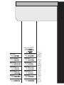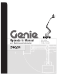
1
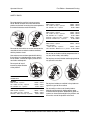
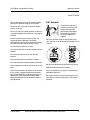
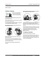
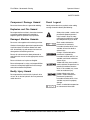
Operator’s Manual
with Maintenance Information
First Edition
Seventeenth Printing
Part No. 46281
Operator's Manual
First Edition • Seventeenth Printing
Important
Read, understand and obey these safety rules and
operating instructions before operating this machine.
Only trained and authorized personnel shall be
permitted to operate this machine. This manual should
be considered a permanent part of your machine and
should remain with the machine at all times. If you have
any questions, call Genie Industries.
Contents
Page
Safety ........................................................................ 1
Legend ....................................................................... 9
Controls .................................................................... 10
Pre-operation Inspection ........................................... 12
Maintenance ............................................................. 14
Function Tests .......................................................... 16
Workplace Inspection ................................................ 21
Operating Instructions ............................................... 22
Transport Instructions ............................................... 27
Decals ...................................................................... 28
Specifications ........................................................... 32
Copyright © 1997 by Genie Industries
Contact us:
First Edition: Seventeenth Printing, October 2002
Internet: http://www.genielift.com
e-mail: [email protected]
"Genie" is a registered trademark of
Genie Industries in the U.S.A. and many other
countries. "GS" is a trademark of Genie
Industries.
These machines comply with
ANSI/SIA 92.6-1999.
Printed on recycled paper
Printed in U.S.A.
Genie GS-2032 & GS-2632 & GS-2046 & GS-2646 & GS-3246
Part No. 46281
Operator's Manual
First Edition • Seventeenth Printing
Safety Rules
Danger
Failure to obey the instructions and
safety rules in this manual will
result in death or serious injury.
Do Not Operate Unless:
You learn and practice the principles of safe
machine operation contained in this operator's
manual.
1 Avoid hazardous situations.
Know and understand the safety rules
before going on to the next section.
2 Always perform a pre-operation inspection.
3 Always perform function tests prior to use.
4 Inspect the workplace.
5 Only use the machine as it was intended.
You read, understand and obey:
Manufacturer's instructions and safety
rules—safety and operator's manuals
and machine decals
employer's safety rules and worksite
regulations
applicable governmental regulations
You are properly trained to safely operate the
machine.
Part No. 46281
Genie GS-2032 & GS-2632 & GS-2046 & GS-2646 & GS-3246
1
Operator's Manual
First Edition • Seventeenth Printing
SAFETY RULES
Electrocution Hazards
Tip-over Hazards
This machine is not electrically insulated and will
not provide protection from contact with or
proximity to electrical current.
Occupants and equipment must not exceed the
maximum platform capacity or the maximum
capacity of the platform extension.
Maximum capacity - GS-2032
Platform retracted
Maintain safe distances from electrical power lines
and apparatus in accordance with applicable
governmental regulations and the following chart.
Voltage
Phase to Phase
Minimum Safe
Approach Distance
Feet
Meters
800 lbs
363 kg
Platform extended - Platform only 550 lbs
Platform extended - Extension only 250 lbs
249 kg
113 kg
Maximum occupants - ANSI and CSA
2
Maximum occupants - CE and Australia
Outdoor use
Indoor use only
1
2
800 lbs / 363 kg
Extension only Platform only
250 lbs / 113 kg 550 lbs / 249 kg
0 to 300V
Avoid Contact
300V to 50KV
10
3.05
Platform retracted
500 lbs
227 kg
50KV to 200KV
15
4.60
200KV to 350KV
20
6.10
Platform extended - Platform only 250 lbs
Platform extended - Extension only 250 lbs
113 kg
113 kg
350KV to 500KV
25
7.62
500KV to 750KV
35
10.67
750KV to 1000KV
45
13.72
Maximum capacity - GS-2632
Maximum occupants - ANSI and CSA
2
Maximum occupants - CE and Australia
Indoor use only
2
Allow for platform movement, electrical line sway
or sag and beware of strong or gusty winds.
500 lbs / 227 kg
Keep away from the machine if it contacts
energized power lines. Personnel on the ground
or in the platform must not touch or operate the
machine until energized power lines are shut off.
Extension only Platform only
250 lbs / 113 kg 250 lbs / 113 kg
Do not operate the machine during lightning or
storms.
Do not use the machine as a ground for welding.
2
Genie GS-2032 & GS-2632 & GS-2046 & GS-2646 & GS-3246
Part No. 46281
Operator's Manual
First Edition • Seventeenth Printing
SAFETY RULES
Do not raise the platform unless the machine is on
a firm, level surface.
Maximum capacity - GS-2046
Platform retracted
1200 lbs
544 kg
Platform extended - Platform only 950 lbs
Platform extended - Extension only 250 lbs
431 kg
113 kg
Maximum occupants
1200 lbs / 454 kg
2
Extension only Platform only
250 lbs / 113 kg 950 lbs / 431 kg
Do not depend on the tilt alarm as a level indicator.
The tilt alarm sounds on the chassis only when the
machine is on a slope.
Maximum capacity - GS-2646
Platform retracted
1000 lbs
454 kg
Platform extended - Platform only 750 lbs
Platform extended - Extension only 250 lbs
340 kg
113 kg
Maximum occupants - CE
2
Do not alter or disable the limit switches.
Maximum occupants - Australia
Outdoor use
Indoor use only
1000 lbs / 454 kg
If the tilt alarm sounds:
Lower the platform. Move the machine to a firm,
level surface. If the tilt alarm sounds when the
platform is raised, use extreme caution to lower the
platform.
1
2
Do not drive over 0.5 mph / 0.7 km/h with the
platform raised.
Extension only Platform only
250 lbs / 113 kg 750 lbs / 340 kg
Maximum capacity - GS-3246
Platform retracted
700 lbs
318 kg
Platform extended - Platform only 450 lbs
Platform extended - Extension only 250 lbs
204 kg
113 kg
Maximum occupants - ANSI and CSA
2
Maximum occupants - CE and Australia
Outdoor use
Indoor use only
1
2
700 lbs / 318 kg
Part No. 46281
Extension only Platform only
250 lbs / 113 kg 450 lbs / 204 kg
Genie GS-2032 & GS-2632 & GS-2046 & GS-2646 & GS-3246
3
Operator's Manual
First Edition • Seventeenth Printing
SAFETY RULES
Do not operate the machine in strong or gusty
winds. Do not increase the surface area of the
platform or the load. Increasing the area exposed to
the wind will decrease machine stability.
Do not drive the machine on or near uneven terrain,
unstable surfaces or other hazardous conditions
with the platform raised.
Use extreme care and slow speeds while driving
the machine in a stowed position across uneven
terrain, debris, unstable or slippery surfaces and
near holes and drop-offs.
GS-2046
ANSI & CSA - 2 person
CE - Indoor use only - 2 person
CE - Outdoor use - 2 person
180 lbs / 801 N
180 lbs / 801 N
90 lbs / 400 N
GS-2646
ANSI & CSA - 2 person
CE - Indoor use only - 2 person
CE - Outdoor use - 2 person
Australia - Indoor use only - 2 person
Australia - Outdoor use - 1 person
150 lbs / 667 N
150 lbs / 667 N
90 lbs / 400 N
120 lbs / 534 N
45 lbs / 200 N
GS-3246
ANSI & CSA - 2 person
105 lbs / 467 N
CE & Australia Indoor use only - 2 person
105 lbs / 467 N
CE & Australia - Outdoor use - 1 person 45 lbs / 200 N
Do not alter or disable machine components that in
any way affect safety and stability.
Do not place or attach fixed or overhanging loads to
any part of this machine.
Do not push off or pull
toward any object outside
of the platform.
Maximum allowable
manual force
GS-2032
ANSI & CSA - 2 person
CE - Indoor use only - 2 person
CE - Outdoor use - 1 person
GS-2632
ANSI & CSA - 2 person
CE - Indoor use only - 2 person
Australia - Indoor use only - 2 person
4
120 lbs / 534 N
120 lbs / 534 N
45 lbs / 200 N
Do not place ladders or scaffolds in the platform or
against any part of this machine.
100 lbs / 445 N
100 lbs / 445 N
90 lbs / 400 N
Do not modify or alter an aerial work platform.
Mounting attachments for holding tools or other
materials onto the platform, toeboards or guard rail
system can increase the weight in the platform and
the surface area of the platform or the load.
Genie GS-2032 & GS-2632 & GS-2046 & GS-2646 & GS-3246
Part No. 46281
Operator's Manual
First Edition • Seventeenth Printing
SAFETY RULES
Do not replace items critical to machine stability
with items of different weight or specification.
Do not use the machine on a moving or mobile
surface or vehicle.
Be sure all tires are in good condition, castle nuts
are properly tightened and cotter pins are properly
installed.
Do not use batteries that weigh less than the
original equipment. Batteries are used as
counterweight and are critical to machine stability.
Each battery must weigh 65 pounds / 30 kg.
Fall Hazards
Occupants should wear a
safety belt or harness and
comply with applicable
governmental regulations.
Attach the lanyard to the
anchor provided in the
platform.
Do not sit, stand or climb on the platform guard
rails. Maintain a firm footing on the platform floor at
all times.
Do not use the machine as a crane.
Do not push the machine or other objects with the
platform.
Do not contact adjacent structures with the
platform.
Do not tie the platform to adjacent structures.
Do not place loads outside the platform perimeter.
Do not operate the machine with the chassis trays
open.
Do not use the platform controls to free a platform
that is caught, snagged or otherwise prevented
from normal motion by an adjacent structure. All
personnel must be removed from the platform
before attempting to free the platform using the
ground controls.
Part No. 46281
Do not climb down from the platform when raised.
Keep the platform floor clear of debris.
Attach the platform entry chain or close the entry
gate before operating.
Do not operate the machine unless the guard rails
are properly installed and the entry is secured for
operation.
Genie GS-2032 & GS-2632 & GS-2046 & GS-2646 & GS-3246
5
Operator's Manual
First Edition • Seventeenth Printing
SAFETY RULES
Collision Hazards
Do not lower the platform unless the area below is
clear of personnel and obstructions.
Be aware of limited sight
distance and blind spots
when driving or operating.
Be aware of the extended platform position when
moving the machine.
The machine must be on a level surface or secured
before releasing the brakes.
It is recommended that operators wear an approved
hard hat when operating the machine.
Check the work area for overhead obstructions or
other possible hazards.
Limit travel speed according to the condition of the
ground surface, congestion, slope, location of
personnel, and any other factors which may cause
collision.
Do not operate a machine in the path of any crane
or moving overhead machinery unless the controls
of the crane have been locked out and/or
precautions have been taken to prevent any
potential collision.
Crushing Hazards
Keep hands and limbs out of scissors.
Be aware of crushing hazards when grasping the
platform guard rail.
Use common sense and planning when operating
the machine with the controller from the ground.
Maintain safe distances between the operator, the
machine and fixed objects.
Observe and use the color-coded direction arrows
on the platform controls and platform decal plate for
drive and steer functions.
No stunt driving or horseplay while operating a
machine.
6
Genie GS-2032 & GS-2632 & GS-2046 & GS-2646 & GS-3246
Part No. 46281
Operator's Manual
First Edition • Seventeenth Printing
SAFETY RULES
Component Damage Hazard
Decal Legend
Do not use the machine as a ground for welding.
Genie product decals use symbols, color coding
and signal words to identify the following:
Explosion and Fire Hazard
Do not operate the machine in hazardous locations
or locations where potentially flammable or
explosive gases or particles may be present.
Damaged Machine Hazards
Do not use a damaged or malfunctioning machine.
Conduct a thorough pre-operation inspection of the
machine and test all functions before each work
shift. Immediately tag and remove from service a
damaged or malfunctioning machine.
Be sure all maintenance has been performed as
specified in this manual and the appropriate service
manual.
Be sure all decals are in place and legible.
Be sure the operator’s, safety, and responsibilities
manuals are complete, legible and in the storage
container located on the platform.
Bodily Injury Hazard
Do not operate the machine with a hydraulic oil or
air leak. An air leak or hydraulic leak can penetrate
and/or burn skin.
Safety alert symbol—used to alert
personnel to potential personal
injury hazards. Obey all safety
messages that follow this symbol
to avoid possible injury or death.
Red—used to indicate the
presence of an imminently
hazardous situation which, if not
avoided, will result in death or
serious injury.
Orange—used to indicate the
presence of a potentially
hazardous situation which, if not
avoided, could result in death or
serious injury.
Yellow with safety alert symbol—
used to indicate the presence of a
potentially hazardous situation
which, if not avoided, may cause
minor or moderate injury.
Yellow without safety alert
symbol—used to indicate the
presence of a potentially
hazardous situation which, if not
avoided, may result in property
damage.
Green—used to indicate operation
or maintenance information.
Part No. 46281
Genie GS-2032 & GS-2632 & GS-2046 & GS-2646 & GS-3246
7
Operator's Manual
First Edition • Seventeenth Printing
SAFETY RULES
Battery Safety
Component Damage Hazard
Burn Hazards
Do not use any battery charger greater than 24V to
charge the batteries.
Batteries contain acid. Always wear protective
clothing and eyewear when working with batteries.
Electrocution Hazards
Connect the battery charger to a
grounded, AC 3-wire electrical
outlet only.
Inspect daily for damaged cord,
cables and wires. Replace
damaged items before
operating.
Avoid spilling or contacting battery acid. Neutralize
battery acid spills with baking soda and water.
Do not expose the batteries or the charger to
water or rain during charging.
Explosion Hazards
Keep sparks, flames
and lighted tobacco
away from batteries.
Batteries emit an
explosive gas.
Avoid electrical shock from contact with battery
terminals. Remove all rings, watches and other
jewelry.
Tip-over Hazard
Do not use batteries that weigh less than the
original equipment. Batteries are used as
counterweight and are critical to machine stability.
Each battery must weigh 65 pounds / 30 kg.
Lifting Hazard
Use the appropriate number of people and proper
lifting techniques when lifting batteries.
The battery tray should
remain open during the
entire charging cycle.
Do not contact the battery terminals or the cable
clamps with tools that may cause sparks.
8
Genie GS-2032 & GS-2632 & GS-2046 & GS-2646 & GS-3246
Part No. 46281
Operator's Manual
First Edition • Seventeenth Printing
Legend
1 Platform entry chain or entry
gate
9 Platform extension release
pedal
17 Pothole guard
2 Platform entry rail
10 Tilt alarm (under cover)
3 Platform guard rails
11 Transport tie-down
19 Entry ladder/transport
tie-down
4 Lanyard anchorage point
12 Steer tire
20 Battery charger
5 Manual storage container
13 Ground controls
21 Brake release pump knob
6 Platform controls
22 Brake release knob
7 GFCI outlet
14 Auxiliary lowering knob or
button or switch
8 Platform extension
15 LED diagnostic readout
16 Hydraulic oil level indicator
Part No. 46281
18 Non-steer tire
23 Safety arm
(GS-3246: safety arm located
above cylinder mount)
Genie GS-2032 & GS-2632 & GS-2046 & GS-2646 & GS-3246
9
Operator's Manual
First Edition • Seventeenth Printing
Controls
1
1
2
2
3
3
4
4
5
5
6
6
Ground Control Panel
1 Auxiliary lowering/manual
lowering toggle switch or
knob or button
2 Hour meter
10
3 Red Emergency Stop button
4 Breaker for electrical circuits
6 Key switch for platform/off/
ground selection
5 Platform up/down toggle
switch
Genie GS-2032 & GS-2632 & GS-2046 & GS-2646 & GS-3246
Part No. 46281
Operator's Manual
First Edition • Seventeenth Printing
CONTROLS
Joystick Controller
1 Horn
2 Machine on incline symbol: Low
speed operation for inclines
3 Lift function select button with
indicator light
4 Drive function select button with
indicator light
5 Red Emergency Stop button
6 Function enable switch
7 Proportional control handle for lift
and drive functions and thumb
rocker for steer function
8 Error indicator light
9 Power light
10 Battery level indicator
11 Lift function enable button
12 Lift/drive select toggle switch
13 Low battery indicator light
The symbols shown below appear in
the text in this operator’s manual as
an aid to identifying operating
instructions.
Use the symbols on this page to
identify which controller you have on
your machine, and use the symbols
in the text to identify which action to
complete on your controller.
If no symbol is listed for your
controller, then no action is needed.
Two function select buttons
and Emergency Stop button
in upper left corner
One function select button
and Emergency Stop button
in upper left corner
Emergency Stop button in
lower right corner
Part No. 46281
Genie GS-2032 & GS-2632 & GS-2046 & GS-2646 & GS-3246
11
Operator's Manual
First Edition • Seventeenth Printing
Pre-operation Inspection
Fundamentals
It is the responsibility of the operator to perform a
pre-operation inspection and routine maintenance.
Do Not Operate Unless:
You learn and practice the principles of safe
machine operation contained in this operator's
manual.
1 Avoid hazardous situations.
2 Always perform a pre-operation
inspection.
Know and understand the pre-operation
inspection before going on to the next
section.
3 Always perform function tests prior to use.
4 Inspect the workplace.
5 Only use the machine as it was intended.
The pre-operation inspection is a visual inspection
performed by the operator prior to each work shift.
The inspection is designed to discover if anything
is apparently wrong with a machine before the
operator performs the function tests.
The pre-operation inspection also serves to
determine if routine maintenance procedures are
required. Only routine maintenance items specified
in this manual may be performed by the operator.
Refer to the list on the next page and check each
of the items and locations for modifications,
damage or loose or missing parts.
A damaged or modified machine must never be
used. If damage or any variation from factory
delivered condition is discovered, the machine
must be tagged and removed from service.
Repairs to the machine may only be made by a
qualified service technician, according to the
manufacturer's specifications. After repairs are
completed, the operator must perform a
pre-operation inspection again before going on to
the function tests.
Scheduled maintenance inspections shall be
performed by qualified service technicians,
according to the manufacturer's specifications and
the requirements listed in the responsibilities
manual.
12
Genie GS-2032 & GS-2632 & GS-2046 & GS-2646 & GS-3246
Part No. 46281
Operator's Manual
First Edition • Seventeenth Printing
PRE-OPERATION INSPECTION
Pre-operation Inspection
o Be sure that the operator's, safety and
responsibilities manuals are complete, legible
and in the storage container located on the
platform.
o Be sure that all decals are legible and in place.
See Decals section.
o Platform extension
o Scissor pins and retaining fasteners
o Platform control joystick
o Generator (if equipped)
o Counterweight (if equipped)
o Check for hydraulic oil leaks and proper oil level.
Add oil if needed. See Maintenance section.
Check entire machine for:
o Check for battery fluid leaks and proper fluid
level. Add distilled water if needed. See
Maintenance section.
o Dents or damage to machine
Check the following components or areas for
damage, modifications and improperly installed or
missing parts:
o Electrical components, wiring and electrical
cables
o Hydraulic power unit, tank, hoses,
fittings, cylinders and manifolds
o Cracks in welds or structural components
o Be sure that all structural and other critical
components are present and all associated
fasteners and pins are in place and properly
tightened.
o Side rails are installed and bolts are fastened
o Be sure that the chassis trays are in place,
latched and properly connected.
o Battery pack and connections
o Drive motors
o Wear pads
o Tires and wheels
o Limit switches, alarms and horn
o Nuts, bolts and other fasteners
o Platform entry chain (if equipped)
o Platform entry gate (if equipped)
o Beacon and alarms (if equipped)
o Brake release components
o Safety arm
o Pothole guards
Part No. 46281
Genie GS-2032 & GS-2632 & GS-2046 & GS-2646 & GS-3246
13
Operator's Manual
First Edition • Seventeenth Printing
Maintenance
Check the Hydraulic Oil Level
Observe and Obey:
Only routine maintenance items specified in this
manual shall be performed by the operator.
Scheduled maintenance inspections shall be
completed by qualified service technicians,
according to the manufacturer's specifications
and the requirements specified in the
responsibilities manual.
Maintenance Symbols Legend
The following symbols have been
used in this manual to help
communicate the intent of the
instructions. When one or more of
the symbols appear at the
beginning of a maintenance
procedure, it conveys the meaning
below.
Maintaining the hydraulic oil at the proper levels is
essential to machine operation. Improper hydraulic
oil levels can damage hydraulic components. Daily
checks allow the inspector to identify changes in oil
level that might indicate the presence of hydraulic
system problems.
Perform this procedure with the
platform in the stowed position.
1 Visually inspect the oil level in the hydraulic
tank through the sight gauge in the side of the
power unit module.
Result: The hydraulic oil level should be within
the full and add marks on the oil level indicator
decal.
2 Add oil if necessary. Do not overfill.
Hydraulic oil specifications
Hydraulic oil type
Refer to machine decal
Indicates that tools will be required to
perform this procedure.
Indicates that new parts will be required to
perform this procedure.
14
Genie GS-2032 & GS-2632 & GS-2046 & GS-2646 & GS-3246
Part No. 46281
Operator's Manual
First Edition • Seventeenth Printing
MAINTENANCE
Check the Batteries
Proper battery condition is essential to good engine
performance and operational safety. Improper fluid
levels or damaged cables and connections can
result in engine component damage and hazardous
conditions.
This procedure does not need to
be performed on machines with
sealed or maintenance-free
batteries.
Scheduled Maintenance
Maintenance performed quarterly, annually and
every two years must be completed by a person
trained and qualified to perform maintenance on this
machine according to the procedures found in the
service manual for this machine.
Machines that have been out of service for more
than three months must receive the quarterly
inspection before they are put back into service.
Electrocution hazard. Contact with
hot or live circuits may result in
death or serious injury. Remove all
rings, watches and other jewelry.
Bodily injury hazard. Batteries
contain acid. Avoid spilling or
contacting battery acid. Neutralize
battery acid spills with baking soda
and water.
Perform this test after fully
charging the batteries.
1 Put on protective clothing and eye wear.
2 Be sure that the battery cable connections are
tight and free of corrosion.
3 Be sure that the battery retaining fasteners are
in place and secure.
4 Remove the battery vent caps.
5 Check the battery acid level of each battery. If
needed, replenish with distilled water to the
bottom of the battery fill tube. Do not overfill.
6 Install the vent caps.
Part No. 46281
Genie GS-2032 & GS-2632 & GS-2046 & GS-2646 & GS-3246
15
Operator's Manual
First Edition • Seventeenth Printing
Function Tests
Fundamentals
The function tests are designed to discover any
malfunctions before the machine is put into service.
The operator must follow the step-by-step
instructions to test all machine functions.
Do Not Operate Unless:
You learn and practice the principles of safe
machine operation contained in this operator's
manual.
1 Avoid hazardous situations.
2 Always perform a pre-operation inspection.
3 Always perform function tests prior to
use.
A malfunctioning machine must never be used. If
malfunctions are discovered, the machine must be
tagged and removed from service. Repairs to the
machine may only be made by a qualified service
technician, according to the manufacturer's
specifications.
After repairs are completed, the operator must
perform a pre-operation inspection and function
tests again before putting the machine into service.
Know and understand the function tests
before going on to the next section.
4 Inspect the workplace.
5 Only use the machine as it was intended.
The symbols shown below appear in the text in
this operator’s manual as an aid to identifying
operating instructions.
Use the symbols on this page and page 11 to
identify which controller you have on your machine,
and use the symbols in the text to identify which
action to complete on your controller.
If no symbol is listed for your controller, then no
action is needed.
Two function select buttons and
Emergency Stop button in upper left
corner
One function select button and
Emergency Stop button in upper left
corner
Controller with Emergency Stop button in
lower right corner
16
Genie GS-2032 & GS-2632 & GS-2046 & GS-2646 & GS-3246
Part No. 46281
Operator's Manual
First Edition • Seventeenth Printing
FUNCTION TESTS
1 Select a test area that is firm, level and free of
obstruction.
2 Be sure the battery pack is connected.
At the Ground Controls
3 Pull out the platform and ground red Emergency
Stop buttons to the on position.
4 Turn the key switch to ground control.
5 Observe the diagnostic LED readout.
Result: LED should read 23 or --.
Test Emergency Stop
6 Push in the ground red Emergency Stop button
to the off position.
Result: No functions should operate.
Test Auxiliary Lowering/Manual Lowering
10 Activate the up function and raise the platform
approximately 2 feet / 60 cm.
11 Activate the auxiliary lowering/manual lowering
function. Move the toggle switch OR pull the
knob OR push the button.
Result: The platform should lower. The descent
alarm will not sound.
12 Turn the key switch to platform control.
At the Platform Controls
Test Emergency Stop
13 Push in the platform red Emergency Stop button
to the off position.
Result: No functions should operate.
7 Pull out the red Emergency Stop button to
the on position.
Test the Horn
Test the Up/Down Functions
14 Pull the red Emergency Stop button out to the
on position.
The audible warnings on this machine and the
standard horn all come from the same central
alarm. The horn is a constant tone. The descent
alarm sounds at 60 beeps per minute. The alarm
that goes off when the pothole guards have not
deployed sounds at 300 beeps per minute. The
alarm that goes off when the machine is not level
sounds at 600 beeps per minute. An optional
automotive-style horn is also available.
15 Push the horn button.
Result: The horn should sound.
8 Activate the up function.
Result: The platform should raise.
9 Activate the down function.
Result: The platform should lower. The descent
alarm should sound while the platform is
lowering.
Part No. 46281
Genie GS-2032 & GS-2632 & GS-2046 & GS-2646 & GS-3246
17
Operator's Manual
First Edition • Seventeenth Printing
FUNCTION TESTS
Test the Function Enable Switch
Test the Steering
16 Do not hold the function enable switch.
Note: When performing the steer and drive function
tests, stand in the platform facing the steer end of
the machine.
17 Slowly move the control handle in the direction
indicated by the blue arrow, then in the direction
indicated by the yellow arrow.
Result: No functions should operate.
Test the Up/Down Functions
18
Press the lift function select button.
Press and hold the lift function enable
button.
Move the lift/drive selector switch to
the lift position (if equipped).
19 Press and hold the function enable switch on
the control handle.
20 Slowly move the control handle in the direction
indicated by the blue arrow.
Result: The platform should raise. The pothole
guards should deploy.
21 Release the control handle.
23
Press the drive function select switch.
Move the lift/drive selector switch to
the drive position (if equipped).
24 Press and hold the function enable switch on
the control handle.
25 Depress the thumb rocker switch on top of the
control handle in the direction identified by the
blue triangle on the control panel.
Result: The steer wheels should turn in the
direction that the blue triangle points on the
control panel.
26 Depress the thumb rocker switch in the direction
identified by the yellow triangle on the control
panel.
Result: The steer wheels should turn in the
direction that the yellow triangle points on the
control panel.
Result: The platform should stop raising.
22 Press and hold the function enable switch.
Slowly move the control handle in the direction
indicated by the yellow arrow.
Result: The platform should lower. The descent
alarm should sound while the platform is
lowering.
CE models: When lowering the platform, the
platform should stop when it is 7 feet / 2.1 m from
the ground. Be sure the area below the platform is
clear of personnel and obstructions before
continuing. To continue lowering, release the
control handle, wait 5 seconds, then move the
control handle again.
18
Genie GS-2032 & GS-2632 & GS-2046 & GS-2646 & GS-3246
Part No. 46281
Operator's Manual
First Edition • Seventeenth Printing
FUNCTION TESTS
Test Drive and Braking
27 Press and hold the function enable switch on the
control handle.
28 Slowly move the control handle in the direction
indicated by the blue arrow on the control panel
until the machine begins to move, then return
the handle to the center position.
Result: The machine should move in the
direction that the blue arrow points on the
control panel, then come to an abrupt stop.
29 Slowly move the control handle in the direction
indicated by the yellow arrow on the control
panel until the machine begins to move, then
return the handle to the center position.
Result: The machine should move in the
direction that the yellow arrow points on the
control panel, then come to an abrupt stop.
Note: The brakes must be able to hold the machine
on any slope it is able to climb.
Test Limited Drive Speed
30
Press the lift function select button.
Press and hold the lift function enable
button.
Move the lift/drive selector switch to
the lift position (if equipped).
31 Press and hold the function enable switch on
the control handle. Raise the platform
approximately 4 feet / 1.2 m from the ground.
Result: The pothole guards should deploy.
Part No. 46281
32
Press the drive function select switch.
Move the lift/drive selector switch to
the drive position (if equipped).
33 Press and hold the function enable switch on the
control handle. Slowly move the control handle
to the full drive position.
Result: The maximum achievable drive speed
with the platform raised should not exceed
0.75 feet per second / 23 cm per second.
If the drive speed with the platform raised exceeds
0.75 feet per second / 23 cm per second,
immediately tag and remove the machine from
service.
Test the Tilt Sensor Operation
Note: Perform this test from the ground with the
platform controller. Do not stand in the platform.
34 Fully lower the platform.
35 Place a 2x4 or similar piece of wood under both
wheels on one side and drive the machine up
onto them.
36 Raise the platform approximately 7 feet / 2.1 m
from the ground.
Machines produced before 01-01-02:
Result: The tilt alarm will sound at 600 beeps
per minute.
CE and Australia models: The drive function and
the lift function will not operate.
Proceed to step 38.
Genie GS-2032 & GS-2632 & GS-2046 & GS-2646 & GS-3246
19
Operator's Manual
First Edition • Seventeenth Printing
FUNCTION TESTS
Machines produced after 12-31-01:
Result: The platform should stop and the tilt
alarm will sound at 600 beeps per minute.
37 Move the drive control handle in the direction
indicated by the blue arrow, then move the drive
control handle in the direction indicated by the
yellow arrow.
Result: The drive function should not work in
either direction.
38 Lower the platform and remove both pieces of
wood.
Test the Pothole Guards
Note: The pothole guards should automatically
deploy when the platform is raised. The pothole
guards activate two limit switches which control the
machine drive speed. If the pothole guards do not
deploy and the platform is raised above 6 feet /
1.8 m, an alarm sounds and the machine will not
drive.
39 Raise the platform.
Result: When the platform is raised 4 feet /
1.2 m from the ground, the pothole guards
should deploy.
40 Press on the pothole guards on one side, and
then the other.
Result: The pothole guards should not move.
20
41 Lower the platform.
Result: The pothole guards should return to the
stowed position.
42 Place a 2x4 or similar piece of wood under a
pothole guard. Raise the platform.
Result: Before the platform is raised 7 feet /
2.1 m from the ground, an alarm should sound
and the drive function should not work.
43 Lower the platform and remove the 2x4.
Test the Platform Limit Switch
- GS-3246 models
Note: Some GS-3246 models are equipped with a
counterweight in the chassis and do not require this
test. The counterweight is gray and measures 28
inches / 71 cm by 15 inches / 38 cm. Open the
chassis trays to see if your machine is equipped
with this counterweight. If not, you must perform
this test.
44 Raise the platform to approximately 26 feet /
7.9 m.
45 Press and hold the function enable switch on the
control handle.
46 Slowly move the control handle to the full drive
position.
Result: The drive function should not operate.
Lower the platform to drive.
Genie GS-2032 & GS-2632 & GS-2046 & GS-2646 & GS-3246
Part No. 46281
Operator's Manual
First Edition • Seventeenth Printing
Workplace Inspection
Workplace Inspection
Be aware of and avoid the following hazardous
situations:
·
drop-offs or holes
·
bumps, floor obstructions or debris
·
overhead obstructions and high voltage
conductors
You learn and practice the principles of safe
machine operation contained in this operator's
manual.
·
hazardous locations
·
inadequate surface support to withstand all load
forces imposed by the machine
1 Avoid hazardous situations.
·
wind and weather conditions
2 Always perform a pre-operation
inspection.
·
the presence of unauthorized personnel
·
other possible unsafe conditions
Do Not Operate Unless:
3 Always perform function tests prior to use.
4 Inspect the workplace.
Know and understand the workplace
inspection before going on to the next
section.
5 Only use the machine as it was intended.
Fundamentals
The workplace inspection helps the operator
determine if the workplace is suitable for safe
machine operation. It should be performed by the
operator prior to moving the machine to the
workplace.
It is the operator's responsibility to read and
remember the workplace hazards, then watch for
and avoid them while moving, setting up and
operating the machine.
Part No. 46281
Genie GS-2032 & GS-2632 & GS-2046 & GS-2646 & GS-3246
21
Operator's Manual
First Edition • Seventeenth Printing
Operating Instructions
Fundamentals
The Operating Instructions section provides
instructions for each aspect of machine operation.
It is the operator's responsibility to follow all the
safety rules and instructions in the operator's,
safety and responsibilities manuals.
Do Not Operate Unless:
You learn and practice the principles of safe
machine operation contained in this operator's
manual.
1 Avoid hazardous situations.
2 Always perform a pre-operation inspection.
3 Always perform function tests prior to use.
4 Inspect the workplace.
5 Only use the machine as it was intended.
22
Using the machine for anything other than lifting
personnel and tools to an aerial work site is unsafe
and dangerous.
Only trained and authorized personnel should be
permitted to operate a machine. If more than one
operator is expected to use a machine at different
times in the same work shift, they must all be
qualified operators and are all expected to follow all
safety rules and instructions in the operator's,
safety and responsibilities manuals. That means
every new operator should perform a pre-operation
inspection, function tests, and a workplace
inspection before using the machine.
Genie GS-2032 & GS-2632 & GS-2046 & GS-2646 & GS-3246
Part No. 46281
Operator's Manual
First Edition • Seventeenth Printing
OPERATING INSTRUCTIONS
Emergency Stop
To Position Platform
Push in the red Emergency Stop button to the off
position at the ground controls or the platform
controls to stop all functions.
1
Press and hold the lift function enable
button.
Repair any function that operates when either red
Emergency Stop button is pushed in.
Auxiliary Lowering/Manual
Lowering
1 Activate the auxiliary lowering/manual lowering
function. Move the toggle switch OR pull the
knob OR push the button.
Operation From Ground
1 Turn the key switch to ground control.
2 Pull out both ground and platform red
Emergency Stop buttons to the on position.
3 Be sure the battery pack is connected before
operating the machine.
To Position Platform
1 Move the up/down toggle switch according to
the markings on the control panel.
Drive and steer functions are not available from
the ground controls.
Operation From Platform
Press the lift function select button.
Move the lift/drive selector switch to
the lift position (if equipped).
2 Press and hold the function enable switch on the
control handle.
3 Move the control handle according to the
markings on the control panel.
CE models: When lowering the platform, the
platform should stop when it is 7 feet / 2.1 m from
the ground. Be sure the area below the platform is
clear of personnel and obstructions before
continuing. To continue lowering, release the
control handle, wait 5 seconds, then move the
control handle again.
To Steer
1
Press the drive function select button.
Move the lift/drive selector switch to
the drive position.
2 Press and hold the function enable switch on the
control handle.
3 Turn the steer wheels with the thumb rocker
switch located on the top of the control handle.
1 Turn the key switch to platform control.
2 Pull out the ground and platform red Emergency
Stop buttons to the on position.
3 Be sure the battery pack is connected before
operating the machine.
Part No. 46281
Genie GS-2032 & GS-2632 & GS-2046 & GS-2646 & GS-3246
23
Operator's Manual
First Edition • Seventeenth Printing
OPERATING INSTRUCTIONS
Error Indicator Light On
To Drive
1
Press the drive function select button.
Move the lift/drive selector switch to
the drive position.
If the error indicator light is on,
push in and pull out the red
Emergency Stop button to reset
the system.
2 Press and hold the function enable switch on
the control handle.
If the light stays on, tag and remove the machine
from service.
3 Increase speed: Slowly move the control
handle off center.
Drive Select Switch
Decrease speed: Slowly move the control
handle toward center.
Machine on incline symbol:
Low range operation for inclines
Stop: Return the control handle to center or
release the function enable switch.
Move the toggle switch down for normal drive
operation.
Use the color-coded direction arrows on the
platform controls and on the platform to identify
the direction the machine will travel.
Machine travel speed is restricted when the
platform is raised.
Battery condition will affect machine performance.
Machine drive speed and function speed will drop
when the low battery indicator light is on or when
the last light on the battery level indicator is
flashing.
24
Genie GS-2032 & GS-2632 & GS-2046 & GS-2646 & GS-3246
Part No. 46281
Operator's Manual
First Edition • Seventeenth Printing
OPERATING INSTRUCTIONS
To Extend and Retract Platform
1 Step on the platform extension release pedal on
the platform toeboard.
2 Grasp the platform guard rails and carefully push
to extend the platform to the mid-position stop.
3 Step on the release pedal again and push to
fully extend the platform.
Do not stand on the platform extension while trying
to extend it.
4 Step on the platform extension release pedal
and pull to retract the platform to the midposition stop. Step again to fully retract the
platform.
GS-3246 models without chassis counterweight:
The platform extension limit switch will disable the
drive function when the platform is extended and
the platform is raised above 26 ft / 7.9 m. Lower the
platform or retract the platform extension to drive
the machine.
Part No. 46281
Operation From Ground with
Controller
Maintain safe distances between the operator,
machine and fixed objects.
Be aware of the direction the machine will travel
when using the controller.
After Each Use
1 Select a safe parking location—firm level
surface, clear of obstruction and traffic.
2 Lower the platform.
3 Turn the key switch to the off position and
remove the key to secure from unauthorized
use.
4 Chock the wheels.
5 Charge the batteries.
Genie GS-2032 & GS-2632 & GS-2046 & GS-2646 & GS-3246
25
Operator's Manual
First Edition • Seventeenth Printing
OPERATING INSTRUCTIONS
Dry Battery Filling and
Charging Instructions
1 Remove the battery vent caps and permanently
remove the plastic seal from the battery vent
openings.
Battery and Charger Instructions
Observe and Obey:
Do not use an external charger or booster
battery.
Charge the battery in a well-ventilated area.
Use proper AC input voltage for charging as
indicated on the charger.
Use only Genie authorized battery and charger.
2 Fill each cell with battery acid (electrolyte) until
the level is sufficient to cover the plates.
Do not fill to maximum level until the battery
charge cycle is complete. Overfilling can cause the
battery acid to overflow during charging.
Neutralize battery acid spills with baking soda and
water.
3 Install the battery vent caps.
4 Charge the battery.
5 Check the battery acid level when the charging
cycle is complete. Replenish with distilled water
to the bottom of the fill tube. Do not overfill.
To Charge Battery
1 Be sure the batteries are connected before
charging the batteries.
2 Open the battery compartment. The
compartment should remain open for the entire
charging cycle.
3 Remove the battery vent caps and check the
battery acid level. If necessary, add only
enough distilled water to cover the plates. Do
not overfill prior to the charge cycle.
4 Replace the battery vent caps.
5 Connect the battery charger to a grounded AC
circuit.
6 Turn the battery charger on.
7 The charger will indicate when the battery is
fully charged.
8 Check the battery acid level when the charging
cycle is complete. Replenish with distilled water
to the bottom of the fill tube. Do not overfill.
26
Genie GS-2032 & GS-2632 & GS-2046 & GS-2646 & GS-3246
Part No. 46281
Operator's Manual
First Edition • Seventeenth Printing
Transport Instructions
Brake Release Operation
1 Chock the wheels to prevent the machine from
rolling.
Observe and Obey:
Common sense and planning must be applied to
control the movement of the machine when
lifting it with a crane or forklift.
2 Be sure the winch line is properly secured to the
drive chassis tie points and the path is clear of
all obstructions.
3 Turn the brake release knob counterclockwise
to open the brake valve.
4 Pump the brake release pump knob.
After the machine is loaded:
The transport vehicle must be parked on a level
surface.
The transport vehicle must be secured to
prevent rolling while the machine is being
loaded.
Be sure the vehicle capacity, loading surfaces
and chains or straps are sufficient to withstand
the machine weight. See the serial plate for the
machine weight.
1 Chock the wheels to prevent the machine from
rolling.
2 Turn the brake release knob clockwise to reset
the brakes.
Towing the Genie GS-2032, the GS-2632, the
GS-2046, the GS-2646 or the GS-3246 is not
recommended. If the machine must be towed, do
not exceed 2 mph / 3.2 km/h.
The machine must be on a level surface or
secured before releasing the brakes.
Securing to Truck or Trailer for
Transit
Always chock the machine wheels in preparation
for transport.
Use the tie-down points on the chassis for
anchoring down to the transport surface.
Use chains or straps of ample load capacity.
Turn the key switch to the off position and remove
the key before transporting.
Inspect the entire machine for loose or unsecured
items.
Part No. 46281
Genie GS-2032 & GS-2632 & GS-2046 & GS-2646 & GS-3246
27
Operator's Manual
First Edition • Seventeenth Printing
Decals
Decal Inspection
Use the pictures on the next pages to verify that all
decals are legible and in place.
Below is a numerical list with quantities and
descriptions.
Part No. Description
Quantity
Part No. Description
Quantity
28161
Warning - Crush Hand
2
46238
Notice - Error Indicator Light
1
28164
Notice - Hazardous Materials
1
46262
Danger - Battery/Charger Safety
1
28171
Label - No Smoking
1
46285
28174
Label - Power to Platform, 230V
2
Notice - Max Cap 800 lbs, GS-2032,
ANSI & CSA
1
28175
Caution - Compartment Access
1
46286
Notice - Battery Connection Diagram
1
28176
Notice - Missing Manuals
1
46287
Notice - Tire Specification
4
28235
Label - Power to Platform, 115V
2
52063
Notice - Max Cap 800 lbs, GS-2032, CE
1
28236
Warning - Failure To Read . . .
1
52475
Label - Transport Tie-down
5
Caution - Crushing Hazard
1
Notice - Side Force & Wind Speed,
GS-2032, CE
1
31060
Danger - Do Not Alter Limit Switch
2
52494
31508
Notice - Power to Battery Charger
1
52560
31785
Notice - Battery Charger Operating
Instructions
1
52608
Notice - Side Force,GS-2032, ANSI & CSA 1
Platform Control Panel
1
37145
Label - Manual Lowering
1
52864
38149
Label - Patents
1
62055
Cosmetic - Genie GS-2032
2
40434
Label - Lanyard Anchorage
5
65052
Label - ECU Fault Codes
1
43089
Notice - Operating Instructions, Ground
1
72833
Label - Open Latches
2
43090
Notice - Operating Instructions, Platform
1
72853
Danger - Improper Use Hazard
1
Cosmetic - Genie GS-2632
2
Notice - Side Force & Wind Speed,
GS-2632, CE
1
Notice - Side Force, GS-2632,
ANSI & CSA
1
Notice - Side Force, GS-2632,
Australia
1
82368
Label - Chevron Rykon
1
82448
Ground Control Panel
1
43091
Danger - General Safety Rules
1
72973
43094
Ground Control Panel
1
72990
43617
Danger - Tip-over (batteries)
1
43618
Label - Directional Arrows
2
43619
Label - Safety Arm
1
43658
Label - Power to Charger, 230V
1
43696
Danger - Electrocution Hazard
2
44220
Danger/Notice - Brake Release Safety &
Operating Instructions
1
44254
Notice - Max Cap 500 lbs, GS-2632
1
44255
Danger - Crushing Hazard
4
44736
Danger - Tilt Alarm
1
44737
Danger - Tip-over, Trays Open
2
44753
Label - LED Diagnostic Readout
1
44980
Label - Power to Charger, 115V
1
44994
Label - Hydraulic Fluid Level / Dexron
1
28
72992
82307
Genie GS-2032 & GS-2632 & GS-2046 & GS-2646 & GS-3246
Part No. 46281
Operator's Manual
First Edition • Seventeenth Printing
DECALS
Ground
Controls Side
Battery
Part No. 46281
Side
Genie GS-2032 & GS-2632 & GS-2046 & GS-2646 & GS-3246
29
Operator's Manual
First Edition • Seventeenth Printing
DECALS
Decal Inspection
Use the pictures on the next pages to verify that all
decals are legible and in place.
Part No. Description
Below is a numerical list with quantities and
descriptions.
Part No. Description
Quantity
28161
Warning - Crush Hand
2
28164
Notice - Hazardous Materials
1
28171
Label - No Smoking
1
28174
Label - Power to Platform, 230V
2
28175
Caution - Compartment Access
1
28176
Notice - Missing Manuals
1
28235
Label - Power to Platform, 115V
2
28236
Warning - Failure To Read . . .
1
31060
Danger - Do Not Alter Limit Switch
2
31508
Notice - Power to Battery Charger
1
31785
Notice - Battery Charger Operating
Instructions
1
37145
Label - Manual Lowering
1
38149
Label - Patents
1
40434
Label - Lanyard Anchorage
5
43089
Notice - Operating Instructions, Ground
1
43090
Notice - Operating Instructions, Platform
1
43091
Danger - General Safety Rules
1
43094
Ground Control Panel
1
43617
Danger - Tip-over (batteries)
1
43618
Label - Directional Arrows
2
43619
Label - Safety Arm
1
43658
Label - Power to Charger, 230V
1
43696
Danger - Electrocution Hazard
2
44220
Danger/Notice - Brake Release Safety &
Operating Instructions
44254
Notice - Max Cap 500/250, GS-3246, CSA 1
44255
Danger - Crushing Hazard
4
44736
Danger - Tilt Alarm
1
44737
Danger - Tip-over, Trays Open
2
44753
Label - LED Diagnostic Readout
44980
44994
30
Quantity
46238
Notice - Error Indicator Light
1
46262
Danger - Battery/Charger Safety
1
46286
Notice - Battery Connection Diagram
1
46287
Notice - Tire Specification
4
48331
Notice - Max Cap 1000 lbs, GS-2646
1
52084
Notice - Max Cap 1200 lbs, GS-2046
1
52337
Notice - Max Cap 700 lbs, GS-3246
1
52475
Label, Transport Tie-down
5
52494
Caution, Crushing Hazard
1
52561
Notice - Side Force & Wind Speed,
GS-2046, CE
1
Notice - Side Force & Wind Speed,
GS-2646, CE
1
52563
Notice - Side Force & Wind Speed,
GS-3246, CE
1
52609
Notice - Side Force,GS-2046,
ANSI & CSA
1
52562
52610
Notice - Side Force,GS-2646,
ANSI & CSA
1
52864
Platform Control Panel
1
62056
Cosmetic - Genie GS-2046
2
62057
Cosmetic - Genie GS-2646
2
62058
Cosmetic - Genie GS-3246
2
65052
Label - ECU Fault Codes
1
72084
Notice - Side Force & Wind Speed,
GS-3246, CE
1
72120
Notice - Max Side Force, ANSI & CSA
1
78026
Notice - Side Force, GS-2646, Australia
1
78027
Notice - Max. Capacity, GS-2646, Australia 1
78028
Notice - Max. Capacity, GS-3246, CE
and Australia
1
72833
Label - Open Latches
2
72853
Danger - Improper Use Hazard
1
82368
Label - Chevron Rykon
1
1
82447
Label - Auxiliary Lowering
1
Label - Power to Charger, 115V
1
82448
Ground Control Panel
1
Label - Hydraulic Fluid Level / Dexron
1
1
Genie GS-2032 & GS-2632 & GS-2046 & GS-2646 & GS-3246
Part No. 46281
Operator's Manual
First Edition • Seventeenth Printing
DECALS
Ground
Controls Side
Battery
Part No. 46281
Side
Genie GS-2032 & GS-2632 & GS-2046 & GS-2646 & GS-3246
31
Operator's Manual
First Edition • Seventeenth Printing
Specifications
Model
GS-2032
AC outlet in platform
Height, working maximum
26 ft
8.1 m
Height, platform maximum
20 ft
6.1 m
Height, stowed maximum
Rails up - CE
827/8 in
2.1 m
Height, stowed maximum
Rails up - ANSI
781/2 in
Height, stowed maximum
Rails lowered
761/2 in
1.94 m
Height, stowed maximum
Rails off
39 in
99 cm
Platform extension length
Height, guard rails ANSI, CSA and Australia
39 in
99 cm
Drive speeds
431/2 in
1.1 m
Width
32 in
81.3 cm
Length, stowed
96 in
2.44 m
135 in
3.44 m
800 lbs
363 kg
Wheelbase
73 in
1.85 m
Turning radius (outside)
92 in
2.34 m
Turning radius (inside)
0 in
0 cm
4.0 in
10.2 cm
Height, guard rails - CE
Length, platform extended
Maximum load capacity
Ground clearance
Ground clearance
Pothole guards deployed
Maximum hydraulic pressure
(functions)
Controls
241.3 bar
15 x 5 x 111/4
Hydraulic system capacity
5.5 gallons
20.8 liters
1.99 m
Platform dimensions
89 in x 311/4 in
2.26 m x 79.4 cm
Length x width
39 in
99 cm
Stowed, maximum
7/8
in
2.2 mph
3.5 km/h
Platform raised, maximum
Floor Loading
Information
0.5 mph
0.8 km/h
40 ft/54.5 sec
12.2 m/54.5 sec
ANSI
CSA & CE
Australia
GVW+Rated Load
4303 lbs
1952 kg
5306 lbs
2407 kg
Axle load, maximum
2450 lbs
1111 kg
3410 lbs
1547 kg
Wheel load, maximum
1225 lbs
555 kg
1705 lbs
773 kg
123 psi
8.62 kg/cm2
845 kPa
170.5 psi
12.0 kg/cm2
1176 kPa
218 psf
10.42 kPa
268 psf
12.85 kPa
2.2 cm
Localized pressure per tire
30%
Airborne noise emissions
70 dB
Maximum sound level at normal operating workstations
(A-weighted)
Power source
3500 psi
Tires size
Weight
See Serial Plate
(Machine weights vary with option configurations)
Gradeability
standard
4 Batteries, 6V 245AH
Proportional
Occupied pressure
Note: Floor loading information is approximate and
does not incorporate different option configurations.
It should be used only with adequate safety factors.
Continuous improvement of our products is a Genie policy.
Product specifications are subject to change without notice or obligation.
32
Genie GS-2032 & GS-2632 & GS-2046 & GS-2646 & GS-3246
Part No. 46281
Operator's Manual
First Edition • Seventeenth Printing
SPECIFICATIONS
Model
GS-2632
Height, working maximum
32 ft
9.9 m
Height, platform maximum
26 ft
7.9 m
Height, stowed maximum
90 in
2.29 m
Height, stowed maximum
Rails folded
68 in
1.73 m
Maximum hydraulic pressure
(functions)
3500 psi
Platform dimensions
89 in x 311/4 in
2.26 m x 79.4 cm
Platform extension length
39 in
Height, guard rails - CE
43 in
1.1 m
Width
32 in
81.3 cm
Length, stowed
96 in
2.44 m
135 in
3.44 m
500 lbs
227 kg
Wheelbase
73 in
1.85 m
Turning radius (outside)
92 in
2.34 m
Turning radius (inside)
0 in
0 cm
4.0 in
10.2 cm
Length, platform extended
Maximum load capacity
Ground clearance
Ground clearance
Pothole guards deployed
241.3 bar
15 x 5 x 111/4
Tires size
1.17 m
Height, guard rails ANSI, CSA and Australia
39 in
99 cm
99.1 cm
Drive speeds
7 /8
in
2.2 cm
Weight
See Serial Plate
(Machine weights vary with option configurations)
Gradeability
standard
Length x width
461/8 in
Platform height,
Stowed maximum
AC outlet in platform
Stowed, maximum
2.2 mph
3.5 km/h
Platform raised, maximum
0.5 mph
0.8 km/h
40 ft/54.5 sec
12.2 m/54.5 sec
Floor Loading Information
ANSI
CSA
CE
Australia
GVW+Rated Load
5650 lbs
2563 kg
6020 lbs
2731 kg
Axle load, maximum
3630 lbs
1647 kg
3738 lbs
1696 kg
Wheel load, maximum
1815 lbs
823 kg
1869 lbs
848 kg
Localized pressure per tire
25%
181.5 psi
186.9 psi
12.77 kg/cm2 13.15 kg/cm2
1251 kPa
1289 kPa
Airborne noise emissions
70 dB
Maximum sound level at normal operating workstations
(A-weighted)
Occupied pressure
Power source
Note: Floor loading information is approximate and
does not incorporate different option configurations.
It should be used only with adequate safety factors.
Controls
4 Batteries, 6V 245AH
Proportional
286 psf
13.68 kPa
304 psf
14.57 kPa
Continuous improvement of our products is a Genie policy.
Product specifications are subject to change without notice or obligation.
Part No. 46281
Genie GS-2032 & GS-2632 & GS-2046 & GS-2646 & GS-3246
33
Operator's Manual
First Edition • Seventeenth Printing
SPECIFICATIONS
Model
GS-2046
Height, working maximum
26 ft
8.1 m
Height, platform maximum
20 ft
6.1 m
Models with sliding rails
Gradeability
30 %
Airborne noise emissions
70 dB
Maximum sound level at normal operating workstations
(A-weighted)
Power source
Height, stowed maximum
Rails up - CE
827/8
in
2.1 m
Height, stowed maximum
Rails up - ANSI
781/2 in
1.99 m
Height, stowed maximum
Rails lowered
713/4 in
Height, stowed maximum
Rails off
391/4 in
99.7 cm
Height, guard rails ANSI, CSA and Australia
39 in
99.1 cm
Height, guard rails - CE
43 in
1.1 m
Height, stowed maximum
861/8 in
2.19 m
Height, stowed maximum
Rails folded
643/8 in
1.64 m
Platform height,
Stowed maximum
423/8 in
1.08 m
Width
46 in
1.17 m
Length, stowed
96 in
2.44 m
135 in
3.44 m
1200 lbs
544 kg
Wheelbase
73 in
1.85 m
Turning radius (outside)
92 in
2.34 m
Turning radius (inside)
0 in
0 cm
Ground clearance
4 in
10.2 cm
1.82 m
4 Batteries, 6V 245AH
Controls
Proportional
AC outlet in platform
standard
Maximum hydraulic pressure
(functions)
3500 psi
15 x 5 x 111/4
Tires size
Hydraulic system capacity
51/2 gallons
Length x width
Platform extension length
Ground clearance
Pothole guards deployed
89 x 453/4 in
2.26 m x 1.16m
39 in
99 cm
Drive speeds
Stowed, maximum
Platform raised, maximum
All models
Maximum load capacity
20.8 liters
Platform dimensions
Models with folding rails
Length, platform extended
241 bar
7/8
in
2.22 cm
2.2 mph
3.5 km/h
0.5 mph
0.8 km/h
40 ft/54.5 sec
12.2 m/54.5 sec
Floor Loading Information
GVW+Rated Load
5524 lbs
2506 kg
Axle load, maximum
2900 lbs
1315 kg
Wheel load, maximum
1450 lbs
657 kg
Localized pressure per tire
145 psi
10.2 kg/cm2
1000 kPa
Occupied pressure
194 psf
9.30 kPa
Note: Floor loading information is approximate and
does not incorporate different option configurations.
It should be used only with adequate safety factors.
Weight
See Serial Plate
(Machine weights vary with option configurations)
34
Genie GS-2032 & GS-2632 & GS-2046 & GS-2646 & GS-3246
Part No. 46281
Operator's Manual
First Edition • Seventeenth Printing
SPECIFICATIONS
Model
GS-2646
Height, working maximum
32 ft
9.9 m
Height, platform maximum
26 ft
7.9 m
Models with sliding rails
Height, stowed maximum
Rails up - CE
in
2.28 m
Height, stowed maximum
Rails up - ANSI
851/2 in
2.17 m
Height, stowed maximum
Rails lowered
851/2 in
Height, stowed maximum
Rails off
461/8 in
1.17 m
Height, guard rails ANSI, CSA and Australia
39 in
99.1 cm
Height, guard rails - CE
43 in
1.1 m
Height, stowed maximum
897/8 in
2.28 m
Height, stowed maximum
Rails folded
681/8 in
1.73 m
Platform height,
Stowed maximum
461/8 in
1.17 m
2.17 m
Controls
Proportional
AC outlet in platform
standard
Maximum hydraulic pressure
(functions)
3500 psi
Hydraulic system capacity
241.3 bar
15 x 5 x 111/4
5.5 gallons
20.8 liters
89 x 453/4 in
2.26 m x 1.16 m
Length x width
Platform extension length
39 in
99 cm
2.2 mph
3.5 km/h
Drive speeds
Width
46 in
1.17 m
Length, stowed
96 in
2.44 m
135 in
3.44 m
1000 lbs
454 kg
Wheelbase
73 in
1.85 m
Turning radius (outside)
92 in
2.34 m
Turning radius (inside)
0 in
0 cm
Ground clearance
4 in
10.2 cm
7 /8
in
Stowed, maximum
Platform raised, maximum
0.5 mph
0.8 km/h
40 ft/54.5 sec
12.2 m/54.5 sec
Floor Loading Information
ANSI
CSA & Australia
CE
GVW+Rated Load
5646 lbs
2561 kg
6227 lbs
2825 kg
Axle load, maximum
3100 lbs
1406 kg
3726 lbs
1690 kg
Wheel load, maximum
1550 lbs
703 kg
1863 lbs
845 kg
Localized pressure per tire
155 psi
186.3 psi
10.91 kg/cm2 13.11 kg/cm2
1069 kPa
1284 kPa
Occupied pressure
199 psf
9.51 kPa
219 psf
10.49 kPa
2.2 cm
Weight
See Serial Plate
(Machine weights vary with option configurations)
Part No. 46281
4 Batteries, 6V 245AH
Platform dimensions
All models
Ground clearance
Pothole guards deployed
Airborne noise emissions
>70 dB
Maximum sound level at normal operating workstations
(A-weighted)
Tires size
Models with folding rails
Maximum load capacity
30%
Power source
897/8
Length, platform extended
Gradeability
Note: Floor loading information is approximate and
does not incorporate different option configurations.
It should be used only with adequate safety factors.
Genie GS-2032 & GS-2632 & GS-2046 & GS-2646 & GS-3246
35
Operator's Manual
First Edition • Seventeenth Printing
SPECIFICATIONS
Model
GS-3246
Height, working maximum
38 ft
11.75 m
Height, platform maximum
32 ft
9.75 m
Models with sliding rails
25%
Airborne noise emissions
>70 dB
Maximum sound level at normal operating workstations
(A-weighted)
Power source
Height, stowed maximum
Rails up - CE
95 in
2.41 m
Height, stowed maximum
Rails up - ANSI
901/2 in
2.3 m
Height, stowed maximum
Rails lowered
833/4 in
Height, stowed maximum
Rails off
511/4 in
1.3 m
Height, guard rails ANSI, CSA and Australia
39 in
99.1 cm
431/2 in
1.1 m
Height, stowed maximum
95 in
2.41 m
Height, stowed maximum
Rails folded
733/8 in
1.86 m
Platform height,
Stowed maximum
511/4 in
1.3 m
Width
46 in
1.17 m
Length, stowed
96 in
2.44 m
135 in
3.44 m
700 lbs
318 kg
Wheelbase
73 in
1.85 m
Turning radius (outside)
92 in
2.34 m
Turning radius (inside)
0 in
0 cm
Ground clearance
4 in
10.2 cm
Height, guard rails - CE
Gradeability
2.13 m
4 Batteries, 6V 245AH
Controls
Proportional
AC outlet in platform
standard
Maximum hydraulic pressure
(functions)
3500 psi
15 x 5 x 111/4
Tires size
Hydraulic system capacity
5.5 gallons
Length x width
Platform extension length
Ground clearance
Pothole guards deployed
89 x 453/4 in
2.26 m x 1.16 m
39 in
99 cm
Drive speeds
Stowed, maximum
Platform raised, maximum
All models
Maximum load capacity
20.8 liters
Platform dimensions
Models with folding rails
Length, platform extended
241.3 bar
7/8
in
2.2 cm
2.2 mph
3.5 km/h
0.5 mph
0.8 km/h
40 ft/54.5 sec
12.2 m/54.5 sec
Floor Loading Information
GVW+Rated Load
6872 lbs
3117 kg
Axle load, maximum
4040 lbs
1833 kg
Wheel load, maximum
2020 lbs
916 kg
Localized pressure per tire
202 psi 14.21 kg/cm2
1393 kPa
Occupied pressure
242 psf
11.57 kPa
Note: Floor loading information is approximate and
does not incorporate different option configurations.
It should be used only with adequate safety factors.
Weight
See Serial Plate
(Machine weights vary with option configurations)
36
Genie GS-2032 & GS-2632 & GS-2046 & GS-2646 & GS-3246
Part No. 46281
Genie North America
425.881.1800
USA and Canada
800.536.1800
Fax
Genie Australia Pty Ltd.
Genie Holland
Phone +31 70 51 78836
Fax +31 70 51 13993
Genie Scandinavia
Phone +46 31 3409612
Fax +46 31 3409613
Phone +33 (0)2 37 26 09 99
Fax +33 (0)2 37 26 09 98
Genie China
Phone +86 21 53852570
Fax +86 21 53852569
Phone +60 4 228 1235
Fax +60 4 226 6872
Genie Japan
Genie Iberica
Phone +34 93 579 5042
Fax +34 93 579 5059
Phone +81 3 3453 6082
Fax +81 3 3453 6083
Genie Korea
Genie Germany
88520
8852-20
Phone +82 2 558 7267
Fax +82 2 558 3910
Genie Africa
Genie U.K.
Phone +44 (0)1476
Fax +44 (0)1476
Phone +61 7 3375 1660
Fax +61 7 3375 1002
Genie Malaysia
Genie France
Phone +49 (0)4202
Fax +49 (0)4202
425.883.3475
584333
584334
Genie Mexico City
Phone +52 55 5666 5242
Fax +52 55 5666 3241
Phone +27 11 455 0373
Fax +27 11 455 0355
Genie Latin America
Phone +55 11 4055 2499
Fax +55 11 4043 1661
Distributed By:
Phone
Toll Free