1
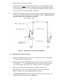
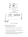
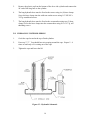
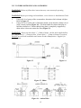
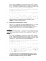
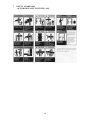
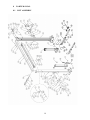
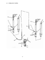
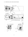
INSTALLATION
and OPERATION
MANUAL
2-POST
2-POST
EELR336A
EELR336A
9000
9000LB.
LB.
(ASYMMETRICAL)
(ASYMMETRICAL)
READ and SAVE THIS
INSTRUCTION MANUAL
Snap-On Tools Corporation
1-800-268-7959
JULY 2005
6-2425
TABLE OF CONTENTS
PAGE
1
SAFETY AND OPERATING INSTRUCTIONS .................................................. 1
2
SPECIFICATIONS................................................................................................... 2
3
CONTENTS............................................................................................................... 3
4
INSTALLATION REQUIREMENTS AND TOOLS ........................................... 3
5
INSTALLATION INSTRUCTIONS ...................................................................... 4
5.1 UNPACKING PROCEDURE ................................................................................ 4
5.2 BAY LAYOUT....................................................................................................... 5
5.3 SAFETY SHUT-OFF BAR INSTALLATION....................................................... 5
5.4 SAFETY SHUT-OFF BAR ADJUSTMENT ......................................................... 6
5.5 TOWER POSITIONING AND SETUP.................................................................. 7
5.6 ROUTING OF EQUALIZATION CABLE ............................................................ 8
5.7 ARM INSTALLATION ......................................................................................... 9
5.8 ARM RESTRAINT INSTALLATION................................................................. 10
5.9 SAFETY RELEASE CABLE ROUTING AND ADJUSTMENT........................ 11
5.10 POWER PACK INSTALLATION ....................................................................... 12
5.11 HYDRAULIC SYSTEM INSTALLATION ........................................................ 13
5.12 HYDRAULIC SYSTEM BLEEDING.................................................................. 14
5.13 TOWER POSITIONING AND ANCHORING .................................................... 15
5.14 SHIMMING OF THE REMAINING TOWER..................................................... 16
6
PERIODIC MAINTENANCE............................................................................... 17
7
SAFETY AWARENESS ........................................................................................ 18
8
PARTS MANUAL .................................................................................................. 19
8.1
8.2
8.3
8.4
8.5
8.6
8.7
LIFT ASSEMBLY ................................................................................................ 19
LIFT ASSEMBLY PARTS LIST ......................................................................... 20
HYDRAULIC SYSTEM ...................................................................................... 22
HYDRAULIC SYSTEM PARTS LIST................................................................ 23
POWER PACK: #6-2055 (AB-1381) 208-230V/1PH/60HZ ................................ 24
POWER PACK PARTS LIST: #6-2055 (AB-1381) 208-230V/1PH/60HZ .......... 25
LIFT MAINTENANCE GUIDELINES – CABLE EQUALIZATION ................ 26
1
1.
2.
3.
4.
5.
6.
7.
8.
9.
10.
11.
12.
13.
14.
SAFETY AND OPERATING INSTRUCTIONS
When using this lift, basic safety precautions should always be followed,
including the following.
Read all instructions in this manual and on the lift.
Inspect lift daily. Do not operate if it malfunctions or problems have been
encountered.
Never attempt to overload the lift. The manufacturer’s rated capacity is shown on
the identification label on the power side column. Do not override the operating
controls or the warranty will be void.
Before driving vehicle between the towers, position the arms to the drive-through
position to ensure unobstructed clearance. Do not hit or run over arms as this
could damage the lift and/or vehicle.
Only trained and authorized personnel should operate the lift. Do not allow
customers or bystanders to operate the lift or be in the lift area.
Position the lift support pads to contact the vehicle manufacturers recommended
lifting points. Raise the lift until the pads contact the vehicle. Check pads for
secure contact with the vehicle. Check all arm restraints and insure they are
properly engaged. Raise the lift to the desired working height.
Some pickup trucks may require an optional truck adapter to clear running boards
or other accessories.
NOTE: Always use all 4 arms to raise and support vehicle.
Caution! Never work under the lift unless the mechanical safety locks are
engaged.
Note that the removal or installation of some vehicle parts may cause a critical
load shift in the center of gravity and may cause the vehicle to become unstable.
Refer to the vehicle manufacturer’s service manual for recommended procedures.
Always keep the lift area free of obstruction and debris. Grease and oil spills
should always be cleaned up immediately.
Never raise vehicle with passengers inside.
Before lowering check area for any obstructions.
Before removing the vehicle from the lift area, position the arms to the drivethrough position to prevent damage to the lift and /or vehicle.
1
2
SPECIFICATIONS
Capacity:
Overall Width:
Width Between Columns:
Drive-Thru Width:
Overall Height:
Under Bar Clearance:
Height to Lowered Lift Pads:
Height to Raised Low Lift Pad:
Height to Raised Low Lift Pad:
Front Arm Retracted Length:
Front Arm Extended Length:
Rear Arm Retracted Length:
Rear Arm Extended Length:
Maximum Lifting Height:
Lift Time:
Power Requirements (Standard):
9000 lbs.
137”
107”
87”
144”
140”
4 ¾”
6 ¼”
9 ¼”
27”
40”
37 ½”
59 ½”
78”
4082 kg
3480 mm
2717 mm
2210 mm
3658 mm
3556 mm
121 mm
159 mm
235 mm
686 mm
1016 mm
953 mm
1511 mm
1981 mm
45 seconds
230 Volts AC, 1 Ph., 60Hz.
Figure 1 – Front View
Figure 2 – Top View
2
3
CONTENTS
The complete lift is contained in two (2) packages:
1. The main structural components are packed in a steel frame.
2. The remaining parts are packed in an accessory box.
Main Structural Components includes:
1pc. Power side tower and carriage assembly
1pc. Slave side tower and carriage assembly
1pc. Crossmember
1pc. Actuator Bar w/ foam
Accessory box contents:
4pcs. Locking Arm Assembly w/arm pins
2pcs. Safety Covers w/Decals
1pc. Hardware Package w/Packing List
1pc. Actuator Extension
1pc. Actuator Mounting Bracket
1pc. Power Pack
4pc. Arm Restraint
1pc. Safety Release Cable
1pc. Hydraulic Hose (Long)
1pc. Hydraulic Hose (Short)
2pcs. Equalizing Cable w/Hex Nuts
1pc. ALI manual “Lifting It Right”
1pc. Automotive Lift Safety Tips
1pc. Automotive Lift, Operation, Inspection and Maintenance manual
1pc. “ALI” Quick Reference Guide
1pc. Owner’s manual
1pc. Safety Shut-off Microswitch Assembly (Components)
4
INSTALLATION REQUIREMENTS AND TOOLS
IMPORTANT: It is the user’s responsibility to provide a satisfactory installation
area for the lift. Lifts should only be installed on level concrete floors with a
minimum thickness of five (5) inches or 130 mm. Concrete must have a minimum
strength of 4000 psi or 30 MPa and should be aged thirty (30) days prior to
installation. Please consult the architect, contractor or engineer if doubt exists as to
the strength and feasibility of the floor to enable proper lift installation and
operation.
It is the user’s responsibility to provide all wiring for electrical hook-up prior to
installation and to insure that the electrical installation conforms to local building
codes. Where required, it is the user’s responsibility to provide an electrical
isolation switch located in close proximity to the lift that will enable emergency stop
capability and isolate electrical power from the lift for any servicing requirements.
3
Tools Required:
a.
b.
c.
d.
e.
f.
g.
h.
i.
j.
k.
l.
m.
5
16ft. Measuring Tape
Chalk Line
Rotary Hammer Drill
3/4” diameter Masonry Drill Bit
Hammer
SAE Wrenches and Ratchet Set
2ft. Level
4ft. Level
Crow Bar
12ft. Step Ladder
Side Cutters
Screwdrivers
4” x 4” Wooden Blocks (for unpacking)
INSTALLATION INSTRUCTIONS
When the lift arrives on site:
• Read the owner’s manual and make sure the installation instructions are fully
understood.
• Check for any freight damages.
• Check the contents of the accessory and hardware boxes to make sure no parts are
missing.
• Gather all the tools listed above.
5.1
UNPACKING PROCEDURE
1.
Important! Place the main structural components on wooden blocks so that the
steel shipping frames can be removed.
2.
Remove the plastic wrapping.
3.
Remove the crossmember, and the actuator bar.
4.
Unbolt the steel shipping frames.
5.
Lay each tower on the floor with the carriage side up.
6.
Check the installation area for obstructions. (Lights, Heating Ducts, Ceiling, Floor
Drains, etc.)
7.
Prepare the bay by selecting the location of the lift relative to the walls. Clear the
installation area of all packaging materials to avoid trip hazards. Draw a chalk
line on the floor to represent the centerline of the bay then draw a second chalk
line at 90° for locating the lift towers. Refer to Figure 3.
4
5.2
BAY LAYOUT
Figure 3 – Bay Layout
5.3
SAFETY SHUT-OFF BAR INSTALLATION
Note: The safety shut off will disconnect the power to the power pack when an
obstruction touches the padded bar or the carriages reach their maximum height.
The safety shut off switch is factory pre-wired. Refer to Figure 4.
Note: This procedure can be done on the floor.
1. Attach the Actuator Mounting Bracket (1-1378) to the crossmember using one ¼” NC
x 3/4” lg. hex head bolt (6-0178), one ¼”ID lockwasher (6-0056), and one ¼” NC
hex nut (6-0032).
2. Attach the Actuator Bar to the Actuator Mounting Bracket using one ¼” NC x 1 ½”
lg. hex head bolt (6-0205), one ¼” ID lockwasher (6-0056), and one ¼” NC hex nut
(6-0032).
3. Slide Safety Shut-Off Microswitch Assembly over the open end of actuator bar and
bolt the assembly to the crossmember using two (2) ¼” NC x ¾” lg. hex head bolts
(6-0178), two (2) ¼” ID lockwashers (6-0056), and two (2) ¼” NC hex nut (6-0032).
4. Install the ¼” NC x 2” lg. hex bolt (6-0741) into the actuator extension (1-1379) then
attach the ¼” NC hex nut (6-0032) from the other side to hold the bolt in place.
5
Figure 4 – Safety Shut-Off Bar Installation
5.4
SAFETY SHUT-OFF BAR ADJUSTMENT
Note: This procedure must be done last. Refer to Figure 4.
1. When the lift is fully installed, leveled and operational, extend the carriages to their
full upper limit.
2. Lower the carriages about ¼” to ½”.
3. Bolt the Actuator Extension onto the open end of actuator bar using two (2) ¼” NC x
1 ¼” lg. hex head bolts (6-0027), two (2) ¼” ID lockwashers (6-0056), and two (2)
¼” NC hex nuts (6-0032).
4. Adjust the ¼” NC x 2” lg. hex bolt so that the end of the bolt is in contact with the
carriage. Tighten the ¼” NC hex nut on the bolt.
6
5.5
TOWER POSITIONING AND SETUP
1. Locate the power side and slave side towers and position them as shown in Figure 3.
Double check all the dimensions in the layout.
2. Using a stepladder, install the crossmember using eight (8) ½”-16UNC x 1 ¼” lg. hex
head bolts, eight (8) ½” ID lock washers, eight (8) ½” hex nuts and eight (8) ½”flat
washers. See Figure 5
3. Check the towers to make sure they are located, and positioned in the correct location.
Refer to Figure 3.
Figure 5 – Crossmember Assembly
7
5.6
ROUTING OF EQUALIZATION CABLE
1. Manually lift the carriages to the first safety latch.
2. Remove equalizing cables from the accessory kit box, and then locate the (8) ½”13UNC nuts from a polybag in the hardware kit box.
3. Equalizing cables are to be routed as shown in Fig. 6a. Using the first cable, insert the
short threaded stud through the 9/16”dia. hole at the bottom of the carriage, and feed
upwards until the stud comes through the top of the carriage. Place a ½”-13UNC nut
at the center of the stud, and then firmly tighten a second nut up against it using two
wrenches. Pull the cable back down though the bottom of the carriage.
(Fig. 6b - cross-sectional view of bottom of carriage).
4. At the bottom of the column, remove the hitch pin, pulley pin and pulley from the
baseplate (Fig. 6c). Route equalizing cable around pulley and reassemble the pulley
to the baseplate. IMPORTANT – Hitch pin must be installed securely. Then route
the cable up through the carriage, around the pulley at the top of the column, across
the crossmember, around the pulley at the top of the other column and then down
(Fig 6a). Insert the threaded stud into the 9/16” Dia. hole in the top of the other
carriage.
Figure 6a
Figure 6b
Figure 6c
5. Use a wrench to hold the top of the threaded stud to prevent it from rotating. Hand
tighten (2) ½”-13 UNC nuts onto the threaded stud enough to remove all visible cable
slack (Step A). Repeat steps 2 to 5 for the other equalizing cable.
6. Using a wrench to hold the top of the threaded stud, to prevent it from rotating,
tighten the first nut approximately 1 ½” (Step B) past the hand tightened position.
Then firmly tighten the second nut against the first one to lock it in place (Step C).
Repeat for the other cable.
STEP A
STEP B
Figure 6
8
STEP C
5.7
ARM INSTALLATION
1.
Remove the four (4) 5/16”-18UNC x 3/4”LG. hex head bolts that are holding the
arm pins to the arm. Install the arms on the carriages.
2.
Grease and insert arm pins. Align the notch on each arm pin with the tapped hole
on the arm, and using the 5/16”-18UNC x 3/4”LG. hex head bolt removed in
previous step, reinstall and tighten securely.
3.
Using two (2) 5/16”-18UNC x 1 ¼” LG. hex head bolts and two (2) 5/16”
flatwashers, attach each arm restraint gear as shown in Figure 6.
FRONT
REAR
Figure 6 – Arm Installation
9
5.8
ARM RESTRAINT INSTALLATION
1. Refer to Figure 7 - arm restraint installation.
2. Loosen the two 5/16 hex bolts which secure the arm restraint gear to the formed
upper ear.
3. Insert arm lock handle weldment through holes in carriage weldment. Arm lock
handle must pass through holes in top and bottom of carriage tube.
4. Adjust arm restraint gear so that lock engages smoothly through entire range of arm
motion. Tighten both 5/16 hex bolts.
5. Repeat above steps for all arms.
6. Lift arms approximately 30” off the ground
7. Slide arm lock spring over outboard leg of arm lock handle (leg which is nearest
tower).
8. Apply spring retainer cap to the end of the leg which passes through arm lock spring.
Using a hammer, tap this retainer securely to arm lock leg.
Figure 7 – Arm Restraint Installation
10
SAFETY RELEASE CABLE ROUTING AND ADJUSTMENT
The mechanical safety automatically engages. To release the mechanical safety, you must
first raise the lift approximately 2”, then pull the safety release lever down. This disengages
the power side safety dog and activates the safety cable to release the slave side safety dog.
1.
Install the safety release bracket on each tower as shown in Figure 8. Attach the
safety pulley to the bracket using the 3/8” x 5/8” LG. shoulder bolt, 5/16”
lockwasher and 5/16” hex nut. Attach the pulley bracket, complete with pulley, to
the tower using the 5/16” x 3/4” LG. hex bolt, 5/16” flat washer, 5/16” lockwasher,
and 5/16” hex nut.
Figure 8 – Safety Release Cable Bracket
2.
Refer to Figure 9 for safety release cable routing. The end of the cable that has a
collar attaches to the slave side tower. The free end is fixed to the power side tower
using two (2) wire rope clips.
3.
Install the safety release handle onto the power side safety dog. Lock the safety
dog into position into position using one 1/2”-13UNC hex nut.
4.
Start routing the safety release cable from the slave side of crossmember. Feed
the cable over the small pulley, then guide the cable down along the inside of the
slave side tower. Pull the cable out through the opening in the back of the tower
near the safety dog.
5.
Guide the cable up under the large pulley towards the end of the safety dog.
Remove the 3/8” x 1 ½” shoulder bolt from the safety dog. Feed the shoulder bolt
through the collar of the safety release cable and then replace the shoulder bolt
securely to the safety dog. NOTE: Make sure shoulder bolt, 3/8” dia. x 1 ½” lg.
(6-0801), is lock tight to safety dog.
11
6.
Repeat step 2 for the power side tower.
7.
Guide the cable up under the large pulley and then over the small pulley towards
the safety dog as shown in Figure 9. Wrap the cable around the thimble (attached
to the safety dog with a 5/16” x 1/2” lg. shoulder bolt) and then clamp it using two
(2) wire rope clips. Do not tighten fully at this stage.
8.
Adjust the cable length so that both safety dogs travel from full engagement position
to full release position when the safety release handle is pulled. Tighten both wire
rope clips firmly when adjustment is completed.
Figure 9 – Safety Release Routing and Adjustment
5.9
POWER PACK INSTALLATION
1.
Remove the red plastic cap located at the rear of the power pack, and install the
"T" fitting located in the hardware kit.
2.
Bolt power pack to the mounting bracket on the power side tower using four (4)
5/16”-18UNC x 1”LG. hex head bolts, four (4) 5/16” ID lock washers, four (4)
5/16” ID flat washers and four (4) 5/16”-18UNC hex nuts. Do not tighten.
3.
Remove the filler cap from the powerpack and fill the reservoir with
approximately 4.5 Gal. (18L) of ISO32 hydraulic oil (10 wt. hydraulic oil).
Remove breather screw when filling and replace when full.
4.
A certified electrician must connect the 230Volt/1Ph power to the motor. The
electrical diagram is provided, refer to Figure 11.
12
Figure 10 – Powerpack Details
T4
MICROSWITCH SHUTOFF
UP CONTROL
(NORMALLY CLOSED
BUTTON
DURING
OPERATION)
(NORMALLY OPEN)
M
T1
230 VOLTS AC
SINGLE PHASE
POWER SUPPLY
Figure 11 – Electrical Diagram
5.10 HYDRAULIC SYSTEM INSTALLATION
REFER TO HYDRAULIC PARTS LIST
1.
Connect the 45° end of the long hose to the “T” fitting on the powerpack.
2.
Connect the 45° end of the short hose to the other end of the “T” fitting.
3.
Remove the plastic cap from the bottom of the power side cylinder and connect
the 90° end of the short hose to the cylinder.
4.
Loop the hydraulic hose up the power side tower, across the overhead and down
the slave side tower. Place rubber grommets (item 68 in the lift assembly)
between the tower and the hose at the top of each tower.
13
5.
Remove the plastic cap from the bottom of the slave side cylinder and connect the
90° end of the long hose to the cylinder.
6.
The long hydraulic hose must be fixed to the towers using six (6) hose clamps.
Screw the hose clamps into the weld nuts on the towers using 1/4”-20UNC x
3/8”lg. round head screws.
7.
The long hydraulic hose must be fixed to the crossmember using two (2) hose
clamps. Screw the hose clamps into the crossmember using #10 x 3/8” lg. self
threading screws.
5.11 HYDRAULIC SYSTEM BLEEDING
1.
Crack the caps located at the top of both cylinders.
2.
Power up 2”-3”. You should hear air escaping around the caps. Repeat 3 - 4
times or until only oil is coming out of the caps.
3.
Tighten the caps and lower the lift.
Figure 12 – Hydraulic Schematic
14
5.12 TOWER POSITIONING AND ANCHORING
WARNING! Failure to follow these instructions may cause an unsafe operating
condition.
WARNING! Before proceeding with installation, review Section 4: Installation & Tools.
1.
2.
Using a 4ft. level on top of the crossmember, determine which column is higher.
Refer to Figure 13.
Using a 2ft. level on the sides of the high column, ensure that the column is level
in the vertical position (Figure 14). Use shims under the column baseplate to
hold the column level. Ensure that the base plate is completely supported by
shims where it does not contact the floor (Figure 15).
WARNING! Do not use more than ½” (13mm) of shims. Anchor bolts supplied allow
for a maximum of ½” (13mm) of shim. If more than ½” (13mm) of shims are required,
DO NOT proceed with installation and contact Product Manufacturer / Supplier for
further details.
Figure 13
Figure 14
Figure 15 - Shims
Figure 16 – Anchor Bolts
15
3.
Refer to Bay Layout (Figure 3) to ensure that the column is still in the proper
position. Using a rotary hammer drill with a 3/4” masonry drill bit, drill holes in
the floor on the high side column using the tower baseplate as a template. Make
sure that the 3/4” masonry drill is in good condition (Figure 16).
4.
Carefully clean out drilling dust from the anchor holes. Hammer in the anchor
bolts (Figure 16). Hand tighten all anchor bolts.
5.
Reconfirm that the column is level front to rear and side to side (Figure 14). Add
or remove shims as required.
6.
Torque all anchor bolts to 150 ft-lbs. (203 Nm), continually checking that the
column is level as you proceed. If anchor bolts do not tighten to 150 ft-lbs. OR
project more than 1 ¾” above the concrete surface (Figure 16), the concrete
MUST be replaced by an appropriate concrete pad. (Consult Product
Manufacturer / Supplier for further details).
5.13 SHIMMING OF THE REMAINING TOWER
1.
Using a 4ft. level on top of the crossmember (Figure 13) and a 2ft. level on the
low side column (Figure 14), shim underneath the baseplate until the
crossmember and column are level. Ensure that the baseplate is completely
supported by shims where it does not contact the floor (Figure 15).
WARNING! Do not use more than ½” (13mm) of shims. Anchor bolts supplied allow
for a maximum of ½” (13mm) of shim. If more than ½” (13mm) of shims are required,
DO NOT proceed with installation and contact Product Manufacturer / Supplier for
further details.
2.
Refer to Bay Layout (Figure 3) to ensure that the column is still in the proper
position. Using a rotary hammer drill with a 3/4” masonry drill bit, drill holes in
the floor on the low side column using the tower baseplate as a template. Make
sure that the 3/4” masonry drill is in good condition (Figure 16).
3.
Carefully clean out drilling dust from the anchor holes. Hammer in the anchor
bolts (Figure 16). Hand tighten all anchor bolts.
4.
Reconfirm that the column is level front to rear and side to side (Figure 14). Add
or remove shims as required.
5.
Torque all anchor bolts to 150 ft-lbs. (203 Nm), continually checking that the
crossmember and column are level as you proceed. If anchor bolts do not tighten
to 150 ft-lbs. OR project more than 1 ¾” above the concrete surface (Figure 16),
the concrete MUST be replaced by an appropriate concrete pad. (Consult Product
Manufacturer / Supplier for further details).
6.
Verify that the entire lift is level both horizontally and vertically to ensure
optimum lifting performance. NOTE: Perform a monthly inspection and
torque all anchor bolts to 150 ft-lbs. (203 Nm).
16
6
PERIODIC MAINTENANCE
1.
Inspect lift daily, to assure the mechanical safety is operating properly.
2.
Check the telescopic arms for movement. Clean any grease or oil from the lifting
adapters.
3.
Raise and lower the lift at the beginning of each shift, without a vehicle on, to
verify the lift is leveled and operating properly. Perform hydraulic leveling
procedure when the lift is out of level.
4.
Lubricate safety dog mechanisms with penetrating oil monthly.
5.
Grease arm pins supports monthly.
6.
Check hydraulic fittings for tightness.
7.
Annual lift inspection as per Automotive Lift Operation, Inspection and
Maintenance (ALOIM).
8.
Apply a small amount of grease to glide bearing tracks periodically.
9.
Check lift for synchronization periodically.
10.
Check bolts on carriage stops for tightness
11.
Change hydraulic oil every two years.
NOTE: If you are unclear call your local representative immediately.
17
7
SAFETY AWARENESS
- AUTOMOTIVE LIFT INSTITUTE (ALI)
18
8
8.1
PARTS MANUAL
LIFT ASSEMBLY
19
8.2
LIFT ASSEMBLY PARTS LIST
ITEM
QTY
DESCRIPTION
PART #
1
2
3
4
7
8
9
11
13
14
15
16
17
18
19
20
21
22
23
24
25
26
27
28
29
30
31
32
33
34
35
36
37
38
39
40
41
43
45
46
47
48
49
50
1
2
8
4
2
6
2
8
12
13
2
4
8
1
4
2
6
3
2
3
1
1
1
1
1
1
1
1
1
1
4
8
2
2
2
1
1
4
8
4
4
4
4
2
TOWER WELDMENT, POWER SIDE
CARRIAGE WELDMENT
GLIDE BEARING
GREASE NIPPLE
PIN, CABLE EQUALIZATION
2-POST PULLEY
HITCH PIN, 1/8” DIA
LOCKWASHER, 1/2”ID
FLAT WASHER, 1/2”ID SAE
HEX NUT, 1/2”-13UNC
SAFETY PIN
COTTER PIN, 1/8”DIA. x 1”LG.
FLAT WASHER, 51/64”ID x 1”OD x 1/16”THK.
SAFETY DOG WELDMENT, POWER SIDE
SELF TAPPING SCREW, #10 X 3/8” LG.
SAFETY SPRING
SELF TAPPING SCREW, #12 x 1/2”LG.
SHOULDER BOLT, 3/8”DIA. x 1”LG.
SAFETY PULLEY
SAFETY CABLE PULLEY
SHOULDER BOLT, 3/8” x 1 1/2” LG.
THIMBLE, 5/32”
CAPACITY DECAL
SERIAL PLATE
TOWER WELDMENT, SLAVE SIDE
SAFETY DOG, SLAVE SIDE
SHOULDER BOLT, 3/8”DIA. x 1 1/2”LG.
ACTUATOR BAR
FOAM GUARD
CROSSMEMBER WELDMENT
CROSSMEMBER PULLEY PIPE, 1/2"LG.
FLAT WASHER, 3/4”ID
CROSSMEMBER PULLEY PIPE, 1 3/4"LG.
CROSSMEMBER PULLEY SHAFT
COTTER PIN, 1/8”DIA. x 1 ½”LG.
SAFETY COVER cw/DECALS, POWER SIDE
SAFETY COVER cw/DECALS, SLAVE SIDE
LOCKWASHER, 3/8” ID
HEX BOLT, 5/16”-18UNC x 3/4” LG.
ARM PIN
HEX BOLT 5/16-18 UNC x 1-1/4 LG.
ARM RESTRAINT GEAR
HEX BOLT, 3/8UNCx3/4”LG.
INNER ARM WELDMENT (LONG)
4-1010
4-1114
2-0772
6-0000
1-1887
1-1898
6-1841
6-0059
6-0248
6-0035
1-2337
6-0267
6-0808
2-1901
6-0169
1-1115
6-1134
6-0206
1-0415
1-1116
6-0801
6-2074
6-1767
6-1111
4-1011
2-0872
6-0801
1-1380
6-1404
3-0694
1-1623
6-0738
1-1626
2-1252
6-0978
0-0204
0-0203
6-0058
6-0423
2-1594
6-2059
1-2618
6-0030
3-0924
20
ITEM
QTY
DESCRIPTION
PART #
51
52
53
54
55
56
60
61
62
63
64
65
66
67
68
69
70
71
72
73
74
75
76
77
78
79
80
81
82
83
84
85
86
87
88
89
90
91
92
93
94
95
96
97
98
99
100
101
2
2
4
4
4
4
6
6
10
10
10
1
1
8
3
2
1
7
2
1
1
1
1
1
1
1
2
1
2
6
1
2
3
6
16
1
1
2
1
1
6
2
4
3
4
4
4
4
OUTER ARM WELDMENT (LONG)
ARM ASSEMBLY (LONG)
CENTER PIN
ADAPTER PIN
LOW POSITION ADAPTER
HIGH POSITION ADAPTER
LOCKWASHER, 1/4” ID
ROUND HEAD SCREW, 1/4”-20UNC x 3/8” LG.
HEX NUT, 3/4”-10UNC
FLAT WASHER, 3/4”ID
WEDGE ANCHOR, 3/4”-10UNC x 5 1/2”LG.
PLASTIC KNOB
SAFETY RELEASE HANDLE
HEX BOLT, 1/2”-13UNC x 1 1/4” LG.
RUBBER GROMMET
EQUALIZING CABLE
SAFETY RELEASE CABLE
HEX HD. NUT 1/4”NC
6/32 SCREW (ELECTRICAL BOX)
MICROSWITCH
LIMIT SWITCH MTG. BRACKET
ELECTRICAL UTILITY BOX
CABLE CONNECTOR
ELEC. CABLE 12/3 x 117”LG.
ACTUATOR EXTENSION
HEX HD. BOLT 1/4”NC x 2”LG.
HEX HD. BOLT 1/4”NC x 1 1/4”LG.
HEX HD. BOLT 1/4”NC x 1 ½”LG.
SHOULDER BOLT, 3/8”DIA. x 5/8”LG.
HEX NUT, 5/16”-18UNC
ACTUATOR MTG. BRACKET
WIRE ROPE CLIP, 1/16”
ELECTRICAL CABLE CLIP, 5/8” ID
TUBE CLAMP, 1/2”
FLATWASHER, 3/8”ID SAE
OUTER ARM WELDMENT (SHORT- R.S.)
OUTER ARM WELDMENT (SHORT – L.S.)
INNER ARM WELDMENT (SHORT)
ARM ASSEMBLY (SHORT – R.S.)
ARM ASSEMBLY (SHORT – L.S.)
LOCKWASHER, 5/16”ID
PULLEY BRACKET
FLATWASHER, 5/16”ID
HEX BOLT ¼-20 x ¾ LG.
ARM LOCK HANDLE WELDMENT
ARM LOCK SPRING
SPRING RETAINER CAP
SNAP RING ¾” EXT
3-0920
4-1135
1-1099
1-2953
3-0583
3-0582
6-0056
6-1353
6-0737
6-0738
6-1379
6-1135
1-1113
6-0046
6-1507
1-1786
1-2058
6-0032
6-1466
6-0916
2-1143
6-1403
6-1133
6-1173
1-1379
6-0741
6-0027
6-0205
6-0069
6-0294
1-1378
6-2060
6-1759
6-0536
6-0062
3-0922
3-0921
3-0925
4-1137
4-1136
6-0296
2-1477
6-0295
6-1078
1-2914
1-2942
6-3086
6-2445
21
8.3
HYDRAULIC SYSTEM
22
8.4
HYDRAULIC SYSTEM PARTS LIST
ITEM
QTY
DESCRIPTION
PART #
1
2
3
4
5
6
7
8
9
10
11
12
13
14
15
16
17
18
1
1
4
4
2
2
2
2
2
2
2
4
4
1
1
1
2
2
POWER PACK
“LIFT OPERATION” DECAL
HEX NUT, 5/16”-18UNC
LOCK WASHER, 5/16”I.D.
PISTON ROD
CYLINDER TUBE
MALE NIPPLE, 1/4”NPT
1/8”NPT TO 1/4” JIC
FLOW CONTROL
PISTON
PISTON SEAL KIT
FLAT WASHER,5/16”I.D.
HEX BOLT, 5/16”-18UNCx1”LG.
BRANCH TEE
HYDRAULIC HOSE (LONG)
HYDRAULIC HOSE (SHORT)
GLAND KIT
1/4” JIC CAP
6-2055
6-2094
6-0294
6-0674
2-1254
2-125501
6-2095
6-0280
6-1510
1-1467
0-0337
6-0295
6-0293
6-1506
2-1486
2-1230
0-0338
6-1884
*
CYLINDER ASSEMBLY (NOT INCL. FLOW CONTROL)
3-062101
23
8.5
POWER PACK: #6-2055 (AB-1381) 208-230V/1PH/60Hz
24
8.6
POWER PACK PARTS LIST: #6-2055 (AB-1381) 208-230V/1PH/60Hz
ITEM
QTY.
DESCRIPTION
PART #
1
2
4
6
7
9
10
11
12
13
14
15
16
17
18
19
20
21
22
24
25
27
28
29
30
31
32
33
34
35
37
38
39
40
41
42
1
1
1
1
1
1
1
1
1
1
1
1
1
1
2
1
1
1
1
1
1
2
1
1
1
1
1
1
4
4
4
1
1
1
1
1
VALVE CARTRIDGE CHECK
LABEL INSTALLATION AUTOHOIST
BREATHER CAP & BLADDER
MOTOR AC 208-230V. 2HP/1PH/60Hz, BLK
LABEL WARNING AUTOHOIST
SPRING 0.480” x 0.063” x 0.42” COMP
RETURN HOSE 3/8” OD x 21.5”
COMPRESSION TUBE NUT
COMPRESSION TUBE SLEEVE
ENDHEAD UNIVERSAL AUTOHOIST
PUMPASSY 2.5 CC/REV. SHORT SPLINE
RELIEF ASSEMBLY FIXED 190 BAR
VALVE CARTRIDGE RELEASE MANUAL
WIRING ASSEMBLY AC 1PH FENNER
BOLT 5/16”-24 x 3.00” TORX G8
COUPLING SAE 9T-20/40 1.260”
PLUMBING PLUG 9/16” SAE
SEAL SHAFT 0.500” x 1.00” x 0.25”
WASHER 0.338” x 0.625” x 0.060” STEEL
PLUMBING PLUG 3/8” NPT
PLUMBING MAGNET
SCREW TAPTITE M6 x 1.0 12MM TORX
COVER ASSY SUCTION
PLUMBING CLAMP HOSE ADJ. INLET
BOLT 5/16”-18 x 1.00” SHCS
NUT ¾”-16 x 1” HEX x 0.250” STEEL
WASHER ¾” INT. TOOTH LOCK
BRACKET – HANDLE ASSY REL BLACK
BOLT M6 x 1.0 35MM SOC HD
WASHER ¼” LOCK HI-COLLAR
BOLT #12-24 x 0.50’ HEX WSHRHD
PLUMBING ASSY INLET 17.24 (3)
RELIEF VALVE CAP ASSEMBLY
TANK PLASTIC 6.7 OS 22.50” BLK
CABLE TIE 8” LONG WHITE
O-RING 2-348 BUNA
6-1087
6-2136
6-1376
6-2474
6-2149
6-2151
6-2152
6-2153
6-2154
6-2155
6-1958
6-1319
6-0880
6-2473
6-1090
6-0774
6-2157
6-2158
6-2159
6-2161
6-2162
6-2164
6-2165
6-2166
6-1392
6-2167
6-2168
6-0776
6-2169
6-2170
6-1091
6-0786
6-1089
6-1399
6-1846
6-0875
25
8.7
LIFT MAINTENANCE GUIDELINES – CABLE EQUALIZATION
Two Post Lifts
Safety Instructions
Read operating and safety manuals before using any lift
Do not operate a lift that has been damaged or is in disrepair
Proper inspection and maintenance is necessary for safe operation
General
Check all hydraulic lines and fittings for pinch points , damage , cracks or leaks
Check all electrical wiring for pinch points , cracks or damage
Check all moving parts for uneven or excessive wear
Repair or replace all damaged , defective , worn or broken components immediately
Cable Equalized Two Post Lift
-
clean and re-grease slide block channels inside of both columns every two months
grease arm pins every two months
check and lubricate safety dogs and safety cable adjustment every two months
dismantle , clean and lubricate arm restraints every two months
dismantle and clean inner arms every four months
lubricate cable pulleys every four months
check equalizing cables and adjust every four months or as required
change hydraulic oil every two years
periodically check anchor bolts and re-torque if required
Hydraulically Equalized Two Post Lift
-
check and adjust hydraulic level weekly or as required
clean and re-grease slide block channels inside of both columns every two months
grease arm pins every two months
check and lubricate safety dogs and safety cable adjustment every two months
dismantle , clean and lubricate arm restraints every two months
dismantle and clean inner arms every four months
change hydraulic fluid every two years
periodically check anchor bolts and re-torque if required
Lubrication : Where grease is required
> multi-purpose lithium grease
Where lubricating oil is required > multi-purpose SAE 30 lubricating oil
Where hydraulic oil is required > ISO 32 10W - non detergent hydraulic oil
26