1
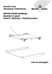
Operating Instructions
Installation Information
METTLER TOLEDO MultiRange
Weighing Platforms PFA579(x)lift / PFA779lift
www.mt.com/support
Content
1.
General information....................................................................................... 4
2.
Safety instructions......................................................................................... 5
3.
3.1
3.2
Preparation ................................................................................................... 7
Selecting installation location ........................................................................... 7
Unpacking ..................................................................................................... 7
4.
Equipotential bonding (for Category 2/3) ........................................................ 8
5.
5.1
5.2
Safety-specific characteristic values............................................................... 9
Ignition protection type PFA575(x) / PFA579(x)................................................. 9
Safety-specific characteristic values for the terminal ............................................ 9
6.
6.1
6.2
Opening and closing the weighing platform................................................... 10
Opening the weighing platform....................................................................... 10
Closing the weighing platform ........................................................................ 11
7.
Transportation ............................................................................................. 12
8.
8.1
8.2
8.3
8.4
8.5
Setting up ...................................................................................................
Above-floor installation without ramp and without floor fastening........................
Above-floor setting up with installation frame ...................................................
Above-floor setting up with corner plates .........................................................
Above-floor setting up with access ramp .........................................................
Pit installation ..............................................................................................
9.
Aligning the weighing platform and laying the cable...................................... 16
10.
Commissioning ........................................................................................... 17
11.
Operating limits .......................................................................................... 18
12.
Planning assemblies ................................................................................... 19
13.
Scale configuration...................................................................................... 20
12
12
13
13
14
16
14. Dimensional drawings ................................................................................. 21
14.1 Dimensions ................................................................................................. 21
14.2 Mounting possibilities .................................................................................. 23
15.
15.1
15.2
15.3
Cleaning the weighing platform....................................................................
Cleaning the exterior (weighing platform closed) ..............................................
Cleaning the interior (weighing platform opened) .............................................
Subsequent treatment....................................................................................
16.
Standard accessories................................................................................... 28
17.
Disposal ..................................................................................................... 31
3
26
26
27
27
1.
General information
These operating instructions and installation information contain all the information on the installation, commissioning and operation of the following weighing platforms:
• PFA579lift / PFA779lift as a stainless version
approved for use in safe areas and in hazardous areas of Zones 2/22
• PFA579xlift as a stainless version
approved for use in hazardous areas of Zones 1/21
The weighing platforms are available with an analog scale interface or a digital IDNet scale
interface.
Information about maintenance, troubleshooting and repairs are contained in the Service Manual ME-22020366.
4
2.
Safety instructions
There is an increased risk of injury and damage when the weighing platforms
are used in hazardous areas! Special care must be taken when working in
such hazardous areas. The rules for behaviour are based on the concept of
"Safe Distribution" established by METTLER TOLEDO.
Competence
▲ The weighing platforms may only be installed, maintained and repaired by authorised
METTLER TOLEDO service personnel.
Ex approval
▲ No modifications may be made to the device and no repair work may be performed on the
modules. Any weighing cells or system modules that are used must comply with the specifications contained in the installation instructions. Non-compliant equipment jeopardises
the intrinsic safety of the system, cancels the "Ex" approval and renders any warranty or
product liability claims null and void.
▲ The safety of the weighing system is only guaranteed when the weighing system is operated, installed and maintained in accordance with the respective instructions.
▲ Also comply with the following:
– the instructions for the system modules and weighing cells
– the regulations and standards in the respective country
– the applicable statutory requirements for electrical equipment installed in hazardous atmospheres in the respective country
– all instructions related to safety issued by the owner
▲ The explosion-protected weighing system must be checked to ensure compliance with the
requirements for safety before being put into service for the first time, following any service
work and every 3 years, at least.
▲ If a replacement part is used, mark the load cells 0745A permanently for the respective
operating location (Category 2GD or Category 3GD)
Operation
▲ Prevent the build-up of static electricity. Always wear suitable working clothes when operating or performing service work in a hazardous area.
▲ Do not use protective coverings for the devices.
▲ Avoid damage to the system components.
5
Installation
▲ Only install and perform maintenance work on the weighing system in the hazardous areas
if the following conditions are fulfilled:
– if the intrinsically safe characteristic values and zone approval of the individual components are in accord with one another
– the owner has issued a permit ("spark permit" or "fire permit")
– the area has been rendered safe and the owner's safety co-ordinator has confirmed that
there is no danger
– the necessary tools and any required protective clothing are provided (danger of the
build-up of static electricity)
▲ The certification papers (certificates, manufacturer’s declarations) must be present.
▲ Lay cables in such a way that they are protected from damage.
▲ Only route cables into the housing of the system modules via the suitable cable coupler
and ensure proper seating of the seals.
Additional requirements for Category 3 (Zone 2/22)
▲ The explosion-protected weighing platform PFA579lift / PFA779lift may only be operated
in Zone 2 and 22 hazardous areas in conjunction with weighing terminals that have a corresponding approval and interface specification.
▲ The connection cable may not be separated from the weighing terminal while it is energised.
▲ Tighten the knurled nut of the IDNet connecting cable with 10 Nm.
Obligations of the operator
▲ Ensure that mounting and maintenance of the weighing platform, in particular of the gas
pressure spring, is carried out exclusively by an authorised METTLER TOLEDO Service
technician.
▲ Ensure that only the spare parts specified by METTLER TOLEDO are used.
▲ Ensure that the weighing platforms with foldable load plate are only operated within a
temperature range of –10 °C to 40 °C. Otherwise, the safety of the gas pressure springs is
not guaranteed.
▲ Ensure that the personnel has been instructed correspondingly before working on the
weighing platforms with foldable load plate and has read and understood these operating
instructions.
6
3.
Preparation
3.1 Selecting installation location
▲ The underground at the installation location must be capable of safely supporting
the weight of the weighing platform at its
support points when it carries the maximum load. At the same time it should be
so stable that no vibrations arise during
weighing work. These requirements also
apply when the weighing platform is integrated in conveying systems and the like.
▲ Ensure that there are no vibrations from
neighbouring machines at the installation
site.
▲ The underground has to be level.
Ambient conditions
➜ Use weighing platforms in a dry environment or in a humid environment.
3.2 Unpacking
The scope of delivery of weighing platform and accessories encompasses the following parts:
Weighing platform
4 rubber retainer plates
1 operating instructions
1 set of labels
1 Declaration of conformity
1 universal oil
1 handle
IDNet option
additionally: 1 Identcard
Installation frame
4 screw anchors
➜ Remove all the parts of the packaging.
7
4.
Equipotential bonding
The equipotential bonding must be installed by a professional electrician when using the
weighing platforms in hazardous areas. METTLER TOLEDO Service only has a monitoring and
consulting function here.
The equipotential bonding terminal is positioned at the terminal box of the weighing platform.
➜ Connect equipotential bonding of all devices (weighing platform, service terminal) in
accordance with the country-specific regulations and standards. In the process it must
be ensured that
–all the device housings are connected to the same potential via the equipotential bonding
terminals,
–no circulating current flows via the cable shielding for intrinsically safe circuits,
–the neutral point for equipotential bonding is as close to the weighing system as possible.
8
5.
Safety-specific characteristic values
5.1 Ignition protection type
Category 3
Category 2
Load cells
Load cell 0745A
II 3G Ex nA II T4
II 3G Ex nL IIC T4
–40 °C ≤ Ta ≤ +50 °C
II 3D Ex tD A22 IP6X T 100 °C
KEMA 03 ATEX 1070
Load cell 0745A
II 2G Ex ia IIC T4
–40 °C ≤ Ta ≤ +50 °C
II 2D Ex tD A21 IP68X T 100 °C
KEMA 03 ATEX 1069
Analog scale
interface
System solution Analog Ex2
II 3G Ex nA II T4
–20 °C ≤ Ta ≤ +60 °C
II 3D Ex tD A22 IP65 T 75 °C
BVS 08 ATEX E 063
Analog Ex1
II 2G Ex ia IIC T4
–20 °C ≤ Ta ≤ +60 °C
II 2D Ex tD A21 IP68 T 75 °C
BVS 04 ATEX E221
System component Analog Ex2
II 3G Ex nA II T4
–20 °C ≤ Ta ≤ +60 °C
II 3D Ex tD A22 IP68 T 75 °C
BVS 08 ATEX E 063
Digital scale
interface
(IDNet)
System solution type Point
II 3G Ex nA II T4
–10 °C ≤ Ta ≤ +40 °C
II 3D Ex tD A22 IP67 T 75 °C
BVS 06 ATEX 098
Point Ex
II 2G Ex ia IIC T4 Gb
–20 °C ≤ Ta ≤ +60 °C
II 2D Ex tb IIIC IP67 T 75 °C Db
BVS 03 ATEX E 432
5.2 Safety-specific characteristic values for the terminal
The following safety-specific characteristic values have to be ensured by the connected weighing terminal:
• Digital scales interface (IDNet, Category 3)
Supply circuit
Umax ≤ 20 VDC
Interface current
Umax,a ≤ 27 VDC
Imax,a≤ 30 mA
• Analog scales interface (Category 3)
Supply circuit
Uimax ≤ 20 VDC
Pimax ≤ 20 W
Uo = Ui
Po = P i
9
6.
Opening and closing the weighing platform
WARNING
Danger of crushing
▲ Only instructed personnel may open/close the weighing platforms with
foldable load plate.
▲ Ensure that there are no persons in the danger area in front of or under
the opened load plate.
▲ Operation only from the right-hand side.
6.1 Opening the weighing platform
1. Remove the weighing sample
assemblies from the load plate.
or
2. Unscrew the blind plug.
3. Turn the handle (1) clockwise into the
load plate until it will go no further.
4. Position yourself next to the weighing
platform.
5. Pull the load plate upward using the
handle.
10
6.2 Closing the weighing platform
1. Position yourself next to the weighing
platform.
2. Press the load plate downward using
the handle.
3. Ensure that the load plate latches in
and lies plane on the load frame.
4. Turn out the handle (1) counterclockwise.
5. Screw the blind plug into the load plate.
11
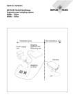
7.
Transportation
Transporting the weighing platform to the installation site
1. Open the weighing platform, see Section
6.1.
2. Fasten a suitable chain or belt sling to
the rings (1).
3. Use a suitable crane or forklift truck to
place the weighing platform to the
installation site.
8.
Setting up
Note
Thanks to the integrated level indicator the weighing platforms can be used even without floor
fastening in compulsory-certification operation (OIML).
8.1 Above-floor installation without ramp and without floor fastening
1. Set up the weighing platform at a suitable location with a level underground.
2. Apply antiskid rubber retainer plates to
the levelling feet.
3. Level the weighing platform using the
level indicator.
12
8.2 Above-floor setting up with installation frame
1. Set up the installation frame at a suitable location with a level underground.
2. Mark the drill position for the installation frame.
3. Drill dowel-holes. Suck off any dirt particles.
4. Screw the installation frame to the floor.
5. Insert the weighing platform in the
installation frame.
8.3 Above-floor setting up with corner plates
1. Set up the corner plates at a suitable
location with a level underground.
2. Place the weighing platform in the corner plates.
3. Align the position of the corner plates.
To this purpose check the gap between
the corner plate and the load frame. The
levelling feet may not be distorted.
4. Mark the position of the corner plates
and lift the weighing platform out of the
corner plates.
5. Mark the drill positions for the corner
plates and drill dowel-holes. Suck off
any dirt particles.
6. Fasten the corner plates to the floor
using dowels.
7. Insert the weighing platform in the corner plates.
13
8.4 Above-floor setting up with access ramp
The following options are available for the above-floor installation with access ramp.
• Installation with installation frame
• Installation with corner plates
• Installation with fastening brackets
Installation with installation frame:
1. Screw the hanger pins into the installation frame.
2. Engage the access ramp into the installation frame.
Installation with corner plates
1. Screw the hanger pins into the corner
plates.
2. Mount the weighing platforms with corner plates, see Section 6.2.
3. Engage the access ramp at the corner
plates.
14
Installation with fastening brackets
1. Connect the access ramp to the supplied fastening brackets.
2. Set up 1 access ramp and 1 corner
plate set (2 pieces) or 2 access ramps
at a suitable location with level underground.
3. Place the weighing platform.
4. Align the position of the access
ramps(s) and, if applicable, the corner
plates. To this purpose check the gap
between the access ramp or corner
plate and the load frame. The levelling
feet may not be distorted.
5. Lift the weighing platform out again. The
access ramp(s) and corner plates may
not be moved in the process.
6. Mark the drill positions of the access
ramps(s) and, if applicable, the corner
plates.
7. Drill dowel-holes. Suck off any dirt particles.
8. Fasten the access ramp(s) and, if applicable, the corner plates with heavy-duty
dowels to the floor.
9. Insert the weighing platform again.
15
8.5 Pit installation
All the mounting and installation aids as well
as a detailed documentation for making the
pit correctly are supplied with the Quick Pit
PFA.
1. Dismount the level indicator.
2. Insert the weighing platform into the
Quick Pit PFA.
3. Insert the connecting cable to the terminal through the holes in the Quick Pit
PFA and through the empty conduit.
Note
If an old DN...sk is to be replaced by a
PFA579(x)lift or PFA779lift, the old pit frame
can be retained. The installation frame PFA is
then required to mount the PFA579(x)lift or
PFA779lift.
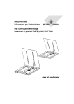
9.
Aligning the weighing platform and laying the cable
1. Align the weighing platform with adjustable leveling feet horizontally using the
integrated level indicator.
2. Lay the connection cable to the terminal
so that it is protected from damage.
3. Ensure clearance to the floor of at least
6 mm in the specified area. If necessary, set the required height using the
leveling feet.
6 mm
16
10. Commissioning
Weighing platforms with analog scale interface
Weighing platforms with an analog scale
interface can be connected to weighing terminals with an integrated A/D converter.
Colour
PFA579lift
PFA579xlift
Terminal
PFA779lift
EXC+
grey
grey
SEN+
yellow
yellow
SIG+
white
white
SIG–
brown
brown
SEN–
green
green
EXC–
blue
pink
When used in hazardous locations ensure
that cable glands suitable for hazardous
locations are used.
1. Connect the weighing platform to the
weighing terminal in accordance with
the adjacent table.
2. Route the connecting cable so that it is
protected from damage.
Weighing platforms with IDNet interface
Weighing platforms with an IDNet interface can be connected to all weighing terminals with
an IDNet connection.
➜ Route the connecting cable so that it is protected from damage.
17
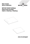
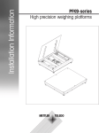
11. Operating limits
The weighing platforms are designed
extremely robustly. However, the load limits
in the following table may not be exceeded.
centred load
Depending on the type of load bearing, the
static bearing, i.e. the maximum permissible
load, amounts to:
load on side
Maximum permissible load in kg
A
one-sided
corner load
B
C
900
450
PFAx79... 300
1500
PFAx79... 600
3500 2300 1150
PFAx79-DS/D/E/ES/FL/ 4500 3000 1500
FM 1500/3000
➜ Avoid falling loads, shock loads as well
as impacts from the side.
➜ Avoid grinding and attrition processes.
Operation with access ramps/pit frames
• The load plate of the weighing platform is an active weighing component. The access
ramps/pit frames are passive. This means that during the weighing process all the wheels
of the transport vehicles have to be on the load plate.
• The air gap between the load plate and the access ramps/pit frames has to be free. The
gap should therefore be inspected regularly and kept free, in particular during the weighing
of granular or small-scale material.
18
12. Planning assemblies
The following points are to be observed when planning assemblies:
• Moving or rotating parts on the weighing platform must be designed so that they do not
affect the weighing result. Rotating parts must be balanced.
• The load frame must be free on all sides so that no connection is established between the
load frame and installation frame, Quick Pit PFA, access ramps or corner plates, even by
falling parts or dirt deposits.
• Cables or hoses between the weighing platform and other machine parts must be laid so
that they do not exert any force on the weighing platform.
• When mounting assemblies, make sure that no metal chips get into the gap between the
DMS weighing cell and the load frame. Clean the gap after completing mounting.
Preload range
The weight of the structural parts permanently mounted onto the weighing platform
is referred to as preload.
If the preload exceeds the zero set range, the
weighing platform has to be electrically
compensated so that the full weighing range
is available.
The zero-set range and the zero adjustment
range must lie within the maximum preload.
Weighing range
Preload *
Preload with 3 x 3000 e MR *
300 kg
400 kg
600 kg
1400 kg
120 kg
1500 kg
2500 kg
500 kg
3000 kg
1200 kg
* In the case of certifiable applications (OIML) the NUD factor (Non Uniform Distribution of
the load) has to be taken into consideration with a corner load supplement of 20% of the
maximum load. If necessary, reduce the zero capturing range.
19
13. Scale configuration
At the factory the scale is configured with a resolution of 1 x 3000 e (standard). Further resolutions are available optionally. Corresponding measuring data plates are applied to the
weighing platform or are included.
Possible configurations
Standard
Weighing
platform
Options
Maximum 1 x 3000 e 2 x 3000 e
load
SR
MR/MI
3 x 3000 e
MR
–
0.05 kg
0.1 / 0.2 kg 0.05 / 0.1 / 0.2 kg
0.1 kg
–
0.2 kg
0.2 / 0.5 kg 0.1 / 0.2 / 0.5 kg
–
–
0.05 kg
0.1 / 0.2 kg 0.05 / 0.1 / 0.2 kg
0.1 kg
–
0.2 kg
300 kg
0.1 kg 0.05 / 0.1 kg
600 kg
0.2 kg
1200 kg
–
1500 kg
0.5 kg
PFAx79..
DS/FL
1 x 6000 e
SR
–
300 kg
0.1 kg 0.05 / 0.1 kg
600 kg
0.2 kg
1200 kg
–
1500 kg
0.5 kg
0.2 / 0.5 kg 0.1 / 0.2 / 0.5 kg
–
3000 kg
1.0 kg
0.5 / 1.0 kg 0.2 / 0.5 / 1.0 kg
0.5 kg
PFAx79..
D/E/ES/FM
SR
Single Range
MR
Multi Range
MI
Multi Interval
–
Notes
• If the configuration is changed, the new measuring data sign has to be affixed to the ID
card.
• Further non-certifiable variants can be configured at weighing platforms with an IDNet interface in Service mode, see the Service Manual A/D Converter Point 22004256.
20
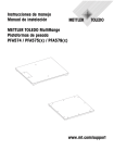
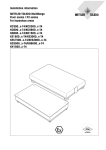
14. Dimensional drawings
14.1 Dimensions
Weighing platforms
B
F
A
E
C
D
Dimensions in mm
A
B
C
D
E
F*
PFAx79-DS
1000
1000
899
899
Ø 40
80
PFAx79-D
1000
1250
899
1149
Ø 40
80
PFAx79-E
1250
1500
1149
1399
Ø 40
80
PFAx79-ES
1500
1500
1399
1399
Ø 40
80
PFAx79-FL
800–1000
800–1000
A–101
B–101
Ø 40
80
PFAx79-FM
800–1500
800–1500
A–101
B–101
Ø 40
80
* Without installation frame
Access ramps
Width
Dimension
G
Dimensions in mm
H
I
J
1000
1000
1150 830 85
1250
1250
1400 830 85
1500
1500
1650 830 85
up to 1000
800–1000 G+150 830 85
up to 1500 1001–1500 G+150 830 85
21
Installation frame and corner plates
A
C
E
3x
B
D
F
13
120
*
Dimensions in mm
120
A
B
C
D
E
F
PFA57.-DS
1000
1000
950
950
820
820
PFA57.-D
1000
1250
950
1200
820
1070
PFA57.-E
1250
1500
1200
1450
1070
1320
PFA57.-ES
1500
1500
1450
1450
1320
1320
PFA57.-FL
800–1000
800–1000
A–50
B–50
A–180
B–180
PFA57.-FM
800–1500
800–1500
A–50
B–50
A–180
B–180
* Locating bore for fastening to the existing pit frame QuickPit DN
22
14.2 Mounting possibilities
PFA579(x)l ift-DS
PFA579(x)l ift-D
1250
1234
1114
1084
1000
984
864
834
546
546
336
256
211
211
136
136
16
0
PFA779l ift-DS
16
0
136
295
290
440
560
710
705
864
814
1000
984
16
0
136
295
290
440
560
710
705
864
814
1000
984
16
0
PFA779l ift-D
1250
1234
1114
1084
1000
984
864
834
546
546
Opening/fastening possibilities are shown hatched.
23
0
16
136
295
290
440
560
16
0
710
705
16
0
864
814
136
1000
984
211
136
16
0
136
295
290
440
560
710
705
864
814
1000
984
336
256
211
PFA579(x)l ift-E
1250
1234
1114
1084
546
336
211
136
16
0
241
236
136
386
506
994
1164
1114
1364
1314
1264
1259
1500
1484
16
0
PFA779l ift-E
1250
1234
1114
1084
796
784
546
466
454
336
136
16
Opening/fastening possibilities are shown hatched.
24
0
16
241
236
136
386
506
994
1364
1314
1264
1259
1164
1114
1500
1484
0
PFA579(x)l ift-ES
1500
1484
1364
1334
546
386
211
136
16
0
241
236
136
386
506
994
1164
1114
1364
1314
1264
1259
1500
1484
16
0
PFA779l ift-ES
1500
1484
1364
1334
1066
1054
756
744
546
446
434
386
211
136
16
0
241
236
136
386
506
994
1364
1314
1264
1259
1164
1114
1500
1484
16
0
Opening/fastening possibilities are shown hatched.
25
15. Cleaning the weighing platform
Maintenance of the weighing platform is limited to its regular cleaning and to oiling of the
surface. The procedure depends on the type of surface and on the ambient conditions
prevalent at the installation site.
CAUTION
Even minor damage, corrosion or flecks of paint on the piston rod lead to
failure of the gas pressure springs.
▲ Protect gas pressure springs against soiling and damage.
▲ Have soiled or damaged gas pressure springs cleaned immediately by
the METTLER TOLEDO Service.
▲ Use only the spare parts specified by METTLER TOLEDO.
Cleaning agents
➜ Only use disinfectants and cleaning agents in accordance with the manufacturer's
instructions.
➜ Do not use highly acidic, highly alkaline or high-chlorine-content cleaning agents. Avoid
substances with a high or low pH value, since the danger of corrosion is otherwise
higher.
15.1 Cleaning the exterior (weighing platform closed)
• Remove corrosive substances, dirt and
deposits regularly from the surface.
• Check the gap between the load plate and
access ramp/pit frame and if appropriate
remove any soiling.
• Water temperature up to 80 °C
80 °C, 100 bars
• High pressure up to 100 bars
• For subsequent treatment see Section
15.3
26
15.2 Cleaning the interior (weighing platform opened)
• Open the weighing platform, see Section
6.1.
• Remove corrosive substances, dirt and
deposits regularly from the surface.
• Check the gap between the load plate and
pit frame and if appropriate remove any
soiling.
60 °C, water jet
• Water temperature up to 60 °C
• Water jet
• Use compressed air to clean dirt particles
from Gap A between the overload protection of the measuring cell and the load
frame of the weighing platform.
Cleaning the interior PFA779lift
The load frame is closed completely. There are no covered edges and no potential
contamination sources in the interior of the load frame.
• Visual inspection and cleaning possibilities in the corner area by cleaning holes.
• Measuring cell area accessible at the side
for additional visual inspection and
cleaning.
• For subsequent treatment see Section
15.3.
15.3 Subsequent treatment
Carry out the following subsequent treatment
to protect the weighing platform against
corrosion:
• After the cleaning process rinse the
weighing platform intensively with clear
water.
• Remove cleaning agent completely.
• Oil the interior and exterior of the weighing
terminal regularly using the supplied
universal oil (suitable for foodstuffs).
27
16. Standard accessories
Access ramp
Order example access ramp
Stainless steel Width
corrugated
AISI304
1250 mm surface
22 016 732
+
22 016 736
Basic model:
Option:
smooth surface corrugated surface
Option:
ground
Stainless steel
AISI304/V2A
Width 1000 mm
Width 1250 mm
Width 1500 mm
Width <1000 mm
Width >1000 mm
22 016 731
22 016 732
22 016 733
22 016 734
22 016 735
22 016 736
RA < 1μm
22 019 491
Stainless steel
AISI316/V4A
Width 1000 mm
Width 1250 mm
Width 1500 mm
Width <1000 mm
Width >1000 mm
22 019 481
22 019 482
22 019 483
22 019 484
22 019 485
22 019 448
RA < 1μm
22 019 491
28
Installation frame
Stainless steel AISI304/V2A
Size DS
Size D
Size E
Size ES
Size FL
Size FM
Stainless steel AISI316/V4A
Size DS
Size D
Size E
Size ES
Size FL
Size FM
22 019 457
22 019 458
22 019 459
22 019 460
22 019 462
22 019 463
22 019 465
22 019 466
22 019 467
22 019 468
22 019 470
22 019 471
Quick Pit PFA
Stainless steel AISI304/V2A,
mounted completely
Size DS
Size D
Size E
Size ES
Size FL
Size FM
Stainless steel AISI316/V4A,
mounted completely
Size DS
Size D
Size E
Size ES
Size FL
Size FM
22 016 693
22 016 694
22 016 695
22 016 696
22 016 698
22 016 699
29
22 019 473
22 019 474
22 019 475
22 019 476
22 019 478
22 019 479
Further accessories
Order No.
Corner plates
Set consisting of 2 pieces
stainless steel AISI304/V2A
stainless steel AISI316/V4A
22 016 703
22 019 492
Connecting extension cable
00 504 134
10 m long, pluggable on both
ends, for remote control of the IDNet
terminal
Connecting set for IDNet terminals
max.
95 m
00 504 133
for progressive extension of the
connecting cable to 100 m,
consisting of two terminal boxes,
box at terminal end with connecting
cable 2.5 m long
Special cable from the roll
100 m, in connection with the
connecting set for progressive
extension of the connecting cable
for IDNet terminals
30
00 504 177
17. Disposal
In accordance with the requirements of the European Directive 2002/96
EC about Waste Electrical and Electronic Equipment (WEEE) this
equipment may not be disposed of in the household refuse.
This applies correspondingly for countries outside the EC in accordance
with the applicable national regulations.
➜ Please dispose of this product in accordance with the local regulations in a separate collection for electrical and electronic equipment.
Should you have any questions, please contact the responsible
authorities or the dealer from whom you purchased this equipment.
If this equipment is passed on (for example for private or commercial/
industrial further use), this specification has to be passed on
correspondingly as well.
Many thanks for your contribution to protecting the environment.
31
METTLER TOLEDO products stand for highest quality and precision. Careful handling in
accordance with these operating instructions as well as regular maintenance and inspection
by our professional customer service ensure the long and reliable function and maintenance
of value of your measuring instruments. Our experienced service team will be pleased to
inform you about corresponding service agreements or calibration services.
Please register your new product under www.mt.com/productregistration, so that we can
inform you about improvements, updates and further important information about your
METTLER TOLEDO product.
*22020361B*
22020361B
Subject to technical changes © Mettler-Toledo (Albstadt) GmbH 05/11 Printed in Germany 22020361B
Mettler-Toledo (Albstadt) GmbH
D-72458 Albstadt
Tel. ++49-7431-14 0
Fax ++49-7431-14 232
www.mt.com/support