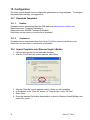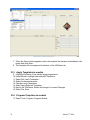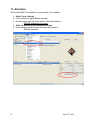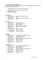
1
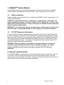
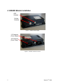
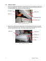
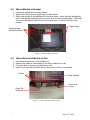
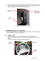
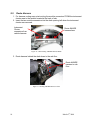
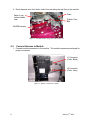
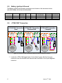
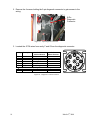
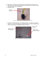
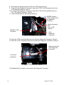
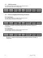
AWARE VEHICLE INTELLIGENCETM INSTALLATION MANUAL FOR INTERNATIONAL® TRUCKS CF500 and CF600 MODULES ARE NOT ACTIVATED WHEN SHIPPED. PLEASE SEE THE ACTIVATION GUIDE. 1 March 6th, 2008 TABLE OF CONTENTS AWARETM Vehicle Models ...........................................................................................................3 1.1. Before Installing......................................................................................................................3 1.2. FCC RF Exposure Information...............................................................................................3 2. How the system works ....................................................................................................................3 3. Kit Installation Components ...........................................................................................................4 3.1. CF Kit Components ................................................................................................................4 3.2. Driver Alert Kit Components (Optional)................................................................................4 3.3. Fuel Tax Indicator Light Components (Optional) ..................................................................4 3.4. Components Provided by Installer..........................................................................................4 4. AWARE Module Installation .........................................................................................................5 4.1. Remove Seats..........................................................................................................................6 4.2. Mount Module to Bracket.......................................................................................................7 4.3. Mount Bracket & Module to Cab ...........................................................................................7 5. AWARE Main Harness Installation................................................................................................8 5.1. Remove Trim ..........................................................................................................................8 5.2. Route Harness .......................................................................................................................10 5.3. Connect Harness to Module..................................................................................................11 5.4. Connect Harness to Vehicle & Cluster .................................................................................12 5.5. Battery, Ignition & Ground...................................................................................................13 5.6. J1708/J1587 Connection.......................................................................................................13 5.7. J1939 Connection..................................................................................................................17 5.8. Accessory Equipment Monitoring Connection.....................................................................17 5.8.1. Fuel Sender ...................................................................................................................17 5.8.2. Park Brake.....................................................................................................................17 5.8.3. Service Brake ................................................................................................................18 6. Antenna Installation ......................................................................................................................20 7. Driver Alert Switch Installation (Optional)..................................................................................22 8. Fuel Tax Reporting Indicator Light (Optional) ............................................................................24 9. Software Upgrade .........................................................................................................................26 10. Configuration ............................................................................................................................28 10.1. Download Templates ........................................................................................................28 10.1.1. Dealers ..........................................................................................................................28 10.1.2. Customers .....................................................................................................................28 10.2. Import Templates into Diamond Logic® Builder.............................................................28 10.3. Apply Templates to module..............................................................................................29 10.4. Program Templates to module ..........................................................................................29 11. Activation..................................................................................................................................30 12. Final Assembly Steps................................................................................................................31 1. APPENDIX A B 2 Program Parameters Manually......................................................................................................32 AWARE Module LED Troubleshooting Table ............................................................................34 March 6th, 2008 1. AWARETM Vehicle Models This installation procedure is for the International® Low Cab Forward Series. Applicable models include International® CF500 and CF600. Other vehicles may not be similar. 1.1. Before Installing Please read this entire document prior to installing the AWARE module. Pay attention to all Cautions and Warnings. CAUTION: Unauthorized antennas, modifications, or attachments could impair call quality, damage the module, or result in violation of FCC regulations. Do not use the module with a damaged antenna. Please contact your local authorized International® dealer for antenna replacement. WARNING: To avoid property damage, personal injury, or death, park the vehicle on a flat level surface, set the parking brake, turn the engine off, and chock the wheels. 1.2. FCC RF Exposure Information In August 1996 the Federal Communications Commission (FCC) of the United States with its action in Report and Order FCC 96-326 adopted an updated safety standard for human exposure to radio frequency electromagnetic energy emitted by FCC regulated transmitters. Those guidelines are consistent with the safety standard previously set by both U.S. and international standards bodies. The design of this cellular module complies with the FCC guidelines and these international standards. WARNING: While the system is in operation, a separation distance of at least 20 centimeters (approximately 8 inches) must be maintained between the cellular antenna and the body of all persons in order to meet the FCC RF exposure guidelines. 2. How the system works The AWAREmodule is a data collection and communication system mounted on a vehicle. It consists of a GPS and cellular antenna and a data communicator module. The data communicator module collects the vehicle’s location and system information and sends it to the network control center through wireless technology. 3 March 6th, 2008 3. Kit Installation Components 3.1. CF Kit Components Kit Part Number: 2591521C91 3620482C91 AWARE module 3628309C92 AWARE main harness 2588150C91 Combined GPS & Cellular Antenna 3804805C1 Bracket, LCF 31048R1 Bolt, M6x30mm, hex flange head 31127R1 Bolt, M6x12mm, hex flange head 3544343C1 Nut, speed, M6x1, U-nut, short, locking 31081R1 Nut, M6, hex flange, PHC finish 575362C1 Cable Tie Tree, low force Activation Guide 0411-310-1605 Deutsch Terminal Remover 3.2. Driver Alert Kit Components (Optional) Kit Part Number: 2589356C91 3593875C2 Driver Alert Switch 3594960C91 Driver Alert Switch Harness 3.3. Fuel Tax Indicator Light Components (Optional) Kit Part Number: 2592410C91 3803693C1 Light, Data Not Logged 3607384C1 Relay, Fuel Tax 3.4. 4 Components Provided by Installer Assorted tie-wraps Splice kit crimp tool Green Lee Punch for standard rectangular Eaton/Cutler Hammer Switch (part number ZTSE4426 from SPX). Diamond Logic® Builder Service tool for programming / provisioning module EZ-Tech® COM cable (IC3 or IC4) March 6th, 2008 4. AWARE Module Installation GPS Antenna Cellular Antenna Figure 1 - Module antenna plugs J1 Connector (Color: Black) J2 Connector (Color: Gray) Figure 2 - Module connector locations 5 March 6th, 2008 4.1. Remove Seats 1. Remove the passenger side seat by unfastening 2 bolts and pushing the seat back to release the sliding clip. One bolt is located at the front of the seat and the other bolt is located between the passenger seat and middle seat. Front bolt Sliding clip Side bolt Passenger seat Middle seat Figure 3 – Passenger seat removed 2. Remove the middle seat by unfastening 2 bolts and releasing the snap on the seat. One bolt is located at the front of the seat and the other bolt is located at the back of the seat, near the driver’s seat. The snap is located under the seat. Back bolt Driver seat Middle seat Front bolt Snap Figure 4 – Middle seat removed 6 March 6th, 2008 4.2. Mount Module to Bracket 1. Locate the module and mounting bracke. 2. Align the module to the top right corner of the bracket. 3. Secure the module to the bracket with 3 bolts and nuts. Insert the bolts through the back of the bracket and tighten the nut down from the front (module side). Two bolts & nuts are attached to the bottom of the module and 1 to the top left hole of the module. 2 Open holes 3 bolts through module & bracket Figure 5 – Module mounted to Bracket 4.3. 1. 2. 3. 4. Mount Bracket & Module to Cab Fold down the back rest of the middle seat. Remove the cable tie tree holding up the liner in the back of cab. Pull down liner to reveal mounting holes in cab. Insert U-nut over the cab holes with the flat portion of the U-nut exposed. U-bolts Rear cab wall Punch hole in liner Cable Tie Tree hole Figure 6 – U-nuts for Bracket on Back of Cab 7 March 6th, 2008 5. Align the bracket’s top holes (with module attached) with the Back of Cab U-nuts. 6. Secure bracket (with module attached) with bolts into the U-nuts. NOTE: The top right corner bolt will go through the bracket and module. Bolt to mount bracket Bolt through module hole to mount bracket Cable tie tree Figure 7 – Module & Bracket mounted to Back of Cab 5. AWARE Main Harness Installation Reference the Cab Master Service Manual for more information. The manual can be found on ISIS® at “http://service.navistar.com”. 5.1. Remove Trim 1. Remove the black trim around the instrument cluster by pulling forward. 2. Remove the steering column panel by unfastening 3 screws on the bottom of the column. 3. Remove the instrument cluster by unfastening 4 screws. Instrument Cluster Black trim Steering Column Figure 8 –Instrument Cluster 8 March 6th, 2008 4. Remove the passenger side door skid plate. Skid plate Figure 9 –Skid Plate 5. Remove the Lower Passenger Dash Panel for harness routing. There are two cable tree ties on each side and a bolt on the lower right side. Cable tree ties Lower Passenger Dash Panel removed Bolt Figure 10 –Lower Passenger Dash Panel 6. Fold back the rubber floor mat starting from the passenger’s side door. The floor mat is one piece and covers the entire floor. Start folding back floor mat Figure 11 –Rubber Floor Mat 9 March 6th, 2008 5.2. Route Harness 1. For harness routing ease, start routing the module connectors FROM the instrument cluster area to the module located at the back of cab. 2. Insert the two module connectors into the dash opening left when the instrument cluster was removed. Instrument Cluster connectors from vehicle harness Route AWARE harness here Figure 12 –Start Routing AWARE Harness HERE 3. Route harness behind the dash down to the cab floor. Route AWARE harness to cab floor Figure 13 –Routing AWARE Harness to floor 10 March 6th, 2008 4. Route harness from front dash, under floor mat along the cab floor to the module. Dash Back of cab behind middle seat Rubber Floor Mat AWARE harness Figure 14 –AWARE Harness along floor under rubber mat 5.3. Connect Harness to Module 1. Connect module connectors to the module. The module connectors are keyed for proper connection. J1 Connector (Color: Black) J2 Connector (Color: Gray) Figure 15 –Harness connection to module 11 March 6th, 2008 5.4. Connect Harness to Vehicle & Cluster Figure 16 –Overview of AWARE harness to vehicle harness & instrument cluster 2. Located the Instrument cluster connectors. 3. Attach the mating end of the AWARE harness to the vehicle’s instrument cluster connectors. 4. Attach the mating end of the AWARE harness to the instrument cluster. AWARE Harness connected to Cluster AWARE Harness connected to Vehicle harness Figure 17 –Harness connection to vehicle harness & instrument cluster 12 March 6th, 2008 5.5. Battery, Ignition & Ground The Battery, Ignition and Ground connections are all made to the instrument cluster. NO ADDITIONAL SPLICING IS REQUIRED. Description Connector Battery Ignition Ground Cluster Cluster Cluster 5.6. Connector Pin Total 12-way 12-way 18-way Cavity Circuit # 2 1 1 3049 489 57 Cluster Circuit Color Black\Light Green Pink\Black Black Aware Circuit Color Red Pink White J1708/J1587 Connection --&RQQHFWLRQ --&RQQHFWLRQ 6WDUW 'LVFRQQHFWHG 9HKLFOH +DUQHVV $ZDUH +DUQHVV 9HKLFOH +DUQHVV & ' % ) * SLQ 'LDJQRVWLF &RQQHFWRU --&RQQHFWLRQ &RPSOHWH $ZDUH +DUQHVV 9HKLFOH +DUQHVV $ZDUH +DUQHVV $ Aware Circuit # BATT IGN GND & ' % $ & ' ) % * SLQ 'LDJQRVWLF &RQQHFWRU $ ) * SLQ 'LDJQRVWLF &RQQHFWRU Figure 18 –Overview of Aware J1708/J1587 connection to the 9-pin diagnostic connector 1. Locate the J1708/J1587 twisted pair of wires (blue & gray) with the 2 pin gray connectors from the AWARE main harness and route them to the 9-pin diagnostic connector. 13 March 6th, 2008 2. Remove the 4 screws holding the 9-pin diagnostic connector to gain access to the wiring. 9-Pin Diagnostic Connector Figure 19 – 9-pin Diagnostic Connector 3. Located the J1708 wires from cavity F and G from the diagnostic connector. Cavity A B C D E F G H J Description Ground Battery J1939+ J1939J1708+ J1708- Color: Vehicle Harness Black Red/Yellow White/Light Green Pink/Light Green Tan/Orange Pink/Light Blue - Color: Aware Harness Blue Gray - Figure 20 – Diagnostic Connector Pinout 14 March 6th, 2008 4. Remove the J1708 wires using the Deutsch Terminal Remover (included in kit). 5. Insert the terminal remover around the wire into the back of the connector. Press terminal remover in as far as possible. 6. Pull back on wire. Terminal Remover Figure 21 – Diagnostic Connector with terminal remover inserted 7. Locate the J1708/J1587 portion of the Aware harness. It contains two harness break-outs, one with a twisted pair of wires with terminals on the end and the other with a connector and an unpopulated mating Connector. Aware J1708 connector Aware J1708 with terminals Aware J1708 mating Connector Figure 22 – AWARE Harness J1708/J1587 Connection 15 March 6th, 2008 8. Disconnect the mating connector from the J1708 connector pair. 9. From the 9-pin Diagnostic Connector, insert the J1708+ Tan & Orange wire into the J1708 mating Connector, Cavity 1. 10. From the 9-pin Diagnostic Connector, insert the J1708- Pink & Light Blue wire into the J1708 mating Connector, Cavity 2. 11. Insert terminal lock into the mating Connector. AWARE Harness: To be inserted into 9pin diagnostic connector Mating Connector with 9-pin J1708 inserted AWARE J1708: Connector 9-Pin Diagnostic Connector Figure 23 – J1708 Connection, In Progress 12. Insert the J1708+ (positive) Blue wire into the 9-pin Diagnostic Connector, Cavity F. 13. Insert the J1708– (negative) Gray wire into the 9-pin Diagnostic Connector, Cavity G. Wires inserted into 9-Pin Diagnostic Connector Connectors reattached Figure 24 – J1708 Connection, Completed 14. Reattached the 4 screws to secure the 9-pin Diagnostic Connector. 16 March 6th, 2008 5.7. J1939 Connection The J1939 connections are all made to the instrument cluster. NO ADDITIONAL SPLICING IS REQUIRED. Description Connector J1939+ J1939- Cluster Cluster 5.8. Connector Pin Total 18-way 18-way Cavity 17 16 Circuit # 1851 1852 Cluster Circuit Color White/Light Green Pink/Light Green AWARE Circuit # J1939+ J1939- AWARE Circuit Color Yellow Green AWARE Circuit # AD1 AWARE Circuit Color Gray Accessory Equipment Monitoring Connection 5.8.1. Fuel Sender The Fuel Level connection is made to the instrument cluster. NO ADDITIONAL SPLICING IS REQUIRED. Description Connector Fuel Level Cluster Connector Pin Total 12-way Cavity 10 Circuit # 29 Cluster Circuit Color Yellow\White Remember to configure with Diamond Logic® Builder as defined in Section 10 Configuration. 5.8.2. Park Brake The Park Brake connection is made to the instrument cluster. NO ADDITIONAL SPLICING IS REQUIRED. Description Connector Park Brake Cluster Connector Pin Total 12-way Cavity 12 Circuit # 162 Cluster Circuit Color Light Green\Red AWARE Circuit # AD2 AWARE Circuit Color Gray Remember to configure with Diamond Logic® Builder as defined in Section 10 Configuration. 17 March 6th, 2008 5.8.3. Service Brake Figure 25 –Overview of Aware Service Brake connection to the Floor Shifter on vehicle 1. Remove the Floor Shifter Column panel by removing 3 screws from the top and one from the bottom. Top screws Bottom screw Figure 26 – Floor Shifter Column 18 March 6th, 2008 2. Disconnect the 6-way floor shifter connector. 3. Connected the AWARE harness to both ends of the floor shifter. Vehicle Harness AWARE Harness AWARE Service Brake Circuit Figure 27 – Service Brake Connection Completed Description Connector Service Brake Shifter Connector Pin Total 6-way Cavity A Circuit # 511 Cluster Circuit Color Light Green AWARE Circuit # AD3 AWARE Circuit Color Gray Remember to configure with Diamond Logic® Builder as defined in Section 10 Configuration. 19 March 6th, 2008 6. Antenna Installation 1. Remove the right side glove box (large) by opening it and unfastening 6 screws. Glove Box Figure 28 –Glove Box 2. Remove the cover from the adhesive on the bottom of the antenna. 3. Secure the antenna on top of the small glove box. Antenna mount Figure 29 - Antenna Location CAUTION – The routing of the AWARE antenna cable is extremely important. There must not be any kinks in the cable, and it must not be routed in such a manner as to make it susceptible to cuts in the outer insulator. Cuts and/or kinks in the cable will adversely affect AWARE signal reception and may permanently damage the AWARE module. 20 March 6th, 2008 4. Route antenna cables behind glove box, inside dash to the cab floor. Antenna mount Glove Box Antenna cables Figure 30 - Antenna Secured with cable routing 5. Route antenna cables with AWARE harness under floor mat to the back of cab. Floor mat (folded back) Antenna cables AWARE Harness Figure 31 - Antenna cables routing on cab floor 6. Route the antenna cables in the cab to the AWARE module. 7. Connect the antenna cables finger tight only. Figure 32 - Antenna cables connected to module 21 March 6th, 2008 7. Driver Alert Switch Installation (Optional) 1. The recommended location for the Driver Alert Switch is the lower left base panel of the instrument panel above to the diagnostic connector. (If the recommended location is not available, select a location that is accessible to the driver but away from normal vehicle operation equipment.) 2. The recommended method to create a rectangular switch slot is to use a Green Lee Punch (P/N ZTSE4426 from SPX). Recommended Location Steering Column Figure 33 - Switch location 3. Insert the Driver Alert Switch from the front side of the panel until it snaps securely in place. 4. Connect the small black 8-pin connector on Driver Alert Switch harness to the AWARE main harness. 5. Splice the panel dimmer feed (blue wire) from the Driver Alert Switch harness to the illumination circuit in the instrument in the vehicle panel dimmer circuit splice pack. Description Connector Dimmer Feed Cluster 22 Connector Pin Total 12-way Cavity 7 Circuit # 19 Cluster Circuit Color Light Blue\Red AWARE Circuit # PANELLGT March 6th, 2008 AWARE Circuit Color Blue 6. Connect the switch connector to the Driver Alert Switch mounted in the panel. Alert Switch Figure 34 - Driver Alert Switch Installed Remember to configure with Diamond Logic® Builder as defined in Section 10 Configuration. 23 March 6th, 2008 8. Fuel Tax Reporting Indicator Light (Optional) 1. The recommended location for the fuel tax “No Data Logged” indicator light is the lower left section of the dash. (If the recommended location is not available, select a location that is accessible to the driver but away from normal vehicle operation equipment.) Recommended Recommended Location Location Steering Column Figure 35 – Fuel Tax light location 2. The recommended method to create a rectangular switch slot is to use a Green Lee Punch (P/N ZTSE4426 from SPX). 3. Insert the “No Data Logged” light into the Plastic Plate until it snaps securely in place. Figure 36 – No Data Logged light 4. Attach the “No Data Logged” connector from the AWARE harness to the “No Data Logged” indicator light. 24 March 6th, 2008 Figure 37 – No Data Logged connector 5. Locate the relay connector on the main AWARE harness. 6. Locate the relay from the Fuel Tax kit. 7. Attach the relay to the connector. Figure 38 – Relay inserted into harness connector 8. Secure the harness with cable ties. 25 March 6th, 2008 9. Software Upgrade Verify the module contains the latest version of software by using Diamond Logic® Builder. Launch Diamond Logic® Builder while connected to the Internet to ensure the latest version of Diamond Logic® Builder software is downloaded onto the computer: 1. Connect your International ® EZ-Tech® or other laptop with Diamond Logic® Builder to the Internet 2. Launch Diamond Logic® Builder. Once Diamond Logic Builder opens, the computer may be disconnected from the internet. 3. Turn ignition Key ON. 4. Attach the computer to the diagnostic connector in the vehicle using an EZ-Tech® COM cable. 5. Allow Diamond Logic® Builder to detect the vehicle and module. 6. On the Select Tab, highlight the “VIN/Name” of the vehicle being programmed 7. Under Module, highlight International® Telematics 8. Select Tools, Get Data, Get Module Data 26 March 6th, 2008 9. Select Edit, Update Software, Update Module a. If the screen displays a message “Already at latest version”, click the “OK” button and proceed to the next section. (The module already has the latest version of software). b. If the Status field next to VIN/Name updates to “Unsaved Changes”, perform the following steps. (The module needs upgraded to the newer version of Software as displayed in the selected module column): 1. Select File, Save 2. Select Tools, Program, Program Module 27 March 6th, 2008 10. Configuration The follow section details how to configure the parameters by using templates. To configure the parameters manually, see Appendix A. 10.1. Download Templates 10.1.1. Dealers Templates can be downloaded from the ISIS web page http://service.navistar.com/ Select menu item: Technical Publications Select menu item: AWARE Technical Publication Scroll down on the screen to view the list of templates. 10.1.2. Customers Templates can be downloaded from http://AwareTechPubs.internationaldelivers.com/ Scroll down on the screen to view the list of templates. 10.2. Import Templates into Diamond Logic® Builder 1. Click on the hyperlink for the applicable template. 2. After the “File Download” screen appears, select Save 3. 4. 5. 6. 28 After the “Save As” screen appears, select a folder you will remember. At the bottom of the “Save As” screen, for “Save as type” select “All Files” Select Save Once the template file finishes downloading, go back to Diamond Logic® Builder, and select File, Import… March 6th, 2008 7. When the Open window appears, select the template file that was downloaded to the laptop and click Open. 8. The template will now appear at the bottom of the VIN/Name list 10.3. Apply Templates to module 9. Highlight VIN/Name of the vehicle being programmed 10. Under Module, highlight International® Telematics 11. Select Edit, Apply Templates… 12. Select the desired template 13. Checkbox only Parameters 14. Select Apply Selected Templates 15. Next to the VIN/Name, Status will change to Unsaved Changes 16. Select File, Save 10.4. Program Templates to module 17. Select Tools, Program, Program Module 29 March 6th, 2008 11. Activation The module MUST be activated to communicate to the website. 1. Select Tools, Activate 2. Follow Diamond Logic® Builder prompts. 3. On the bottom right side of the screen, State will update to: AWARE attempting to connect 4. Allow 10 minutes for the module to activate. 5. Upon activation of the module, the State will update to: AWARE activated 30 March 6th, 2008 12. Final Assembly Steps 1. Reinstall the floor shifter cover 2. Reinstall the large glove box. 3. Reinstall the rubber floor mat. 4. Reinstall the lower passenger dash panel. 5. Reinstall the passenger side skid plate. 6. Reinstall the instrument cluster. 7. Reinstall the steering column cover. 8. Reinstall the dash trim. 9. Reinstall the middle seat. 10. Reinstall the passenger seat. Figure 39 - Trim Panels Reinstalled 31 March 6th, 2008 A Program Parameters Manually Parameters can be programmed manually (instead of using templates) in Diamond Logic® Builder through the following steps: 1. 2. 3. 4. Highlight VIN/Name of the vehicle being programmed Under Module, highlight International® Telematics Select tab Features. Select sub-tab AWARE. Data Sources 5. Select Parameter: Enter Value: 6. Select Parameter: Enter Value: Engine Retarder Status Source None Transmission Retarder Status Source J1587 Fuel Sender 7. Select Parameter: Enter Value: 8. Select Parameter: Enter Value: 9. Select Parameter: Enter Value: 10. Select Parameter: Enter Value: 11. Select Parameter: Enter Value: Fuel Level Source General Purpose Input 1 Analog 1 Mode Analog – VREF biased sensor Analog 1 Filter Coefficient 16 Analog 1 X Values 10, 20, 30, 40, 50 Analog 1 Y Values 0, 63, 125, 188, 250 Park Brake 12. Select Parameter: Enter Value: 13. Select Parameter: Enter Value: 14. Select Parameter: Enter Value: 15. Select Parameter: Enter Value: Parking Brake Switch Status Source General Purpose Input 2 Analog 2 Mode Analog – Battery/Ignition biased sensor Analog 2 X Values 30, 30, 50, 70, 70 Analog 2 Y Values 1, 2, 2, 2, 0 Service Brake 16. Select Parameter: Enter Value: 17. Select Parameter: Enter Value: 18. Select Parameter: Enter Value: 19. Select Parameter: Enter Value: Service Brake Switch Status Source General Purpose Input 3 Analog 3 Mode Analog – Battery/Ignition biased sensor Analog 3 X Values 30, 30, 50, 70, 70 Analog 3 Y Values 1, 2, 2, 2, 0 32 March 6th, 2008 Miscellaneous 20. Select Parameter: Engine Speed Exception RPM Threshold Enter Value: 3600 Driver Alert Switch (If the Driver Alert Switch has been installed, perform the next step.) 21. Select Parameter: Driver Alert Switch Installed Enter Value: Enable 22. Select File, Save. 23. Select Edit, Update Software, Update Module to program the module. 33 March 6th, 2008 B AWARE Module LED Troubleshooting Table Indicated Items LED’s Comments A B C D OFF OFF OFF OFF Heartbeat Slow Flash Steady ON Fast Flash OFF OFF OFF - - - - - - - - - GPS OFF GPS active - - - GPS acquired - OFF Slow Flash Steady ON - - Cellular Modem OFF Cellular Modem signal strength (Low & no service) Cellular Modem signal strength (High) Cellular modem transmitting data - - - - - - - OFF Slow Flash Steady ON Fast Flash Communication on J1939 data link Cellular modem receiving data - - - - - - Slow Flash Fast Flash Power disconnected Sleep mode active Awake mode active Ignition is ON Internal Fault Detected Highest priority for LED “A”. Indicates in Awake and Ignition modes also. - Highest priority for LED “C”. Shall indicate for a minimum of 3 seconds. Highest priority for LED “D”. Shall indicate for a minimum of 3 seconds. Flash Rate Definition Heartbeat = 1 flash every minute Slow Flash = 1 flash every second Fast Flash = 4 flashes every second 34 March 6th, 2008