1
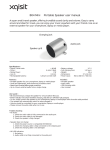
3117-957/02
Service manual
Instruction supplement to
PFAFF 3117
instruction manual
296-12-17 860
Justieranl. engl. 05.96
At the time of printing, all information and illustrations contained in this document were up
to date.
Subject to alteration!
The reprinting, copying or translation of PFAFF Instruction Manuals, whether in whole or in
part, is only permitted with our previous permission and with written reference to the
source.
G.M. PFAFF
Aktiengesellschaft
Postfach 3020
D-67653 Kaiserslautern
Königstr. 154
D-67655 Kaiserslautern
Redaktion / Illustration
HAAS-Publikationen GmbH
D-53840 Troisdorf
Table of contents
Contents ............................................................................... Chapter - Page
1
1.01
1.02
Knuckle switch for machine stop ............................................................................... 1 - 1
2
2.01
Installation and commissioning .............................................................................. 2 - 1
Adjusting the pedal .................................................................................................... 2 - 1
3
3.01
3.02
3.03
3.04
3.05
3.06
3.07
3.08
3.09
3.10
3.11
3.12
3.13
3.14
Adjustment ............................................................................................................... 3 - 1
Elements of operation ............................................................................................. 1 - 1
Foot pedal .................................................................................................................. 1 - 1
Notes on adjustment ................................................................................................. 3 - 1
Tools, gauges and other accessories ......................................................................... 3 - 1
Detector lever ............................................................................................................ 3 - 2
Locking dog ............................................................................................................... 3 - 3
Driving pulleys ............................................................................................................ 3 - 4
Manual switching-off ................................................................................................. 3 - 5
Catch lever ................................................................................................................. 3 - 6
Stroke of the scissors ................................................................................................ 3 - 7
Engaging lever ........................................................................................................... 3 - 8
Presser bar lifting lever .............................................................................................. 3 - 9
Lifting and starting lock .............................................................................................. 3 - 10
Mounting and dismounting the belts ......................................................................... 3 - 11
Mounting the belt guard and aligning the belt catchers ............................................. 3 - 12
Taking up belt slack .................................................................................................... 3 - 13
Elements of operation
1
Elements of operating
1.01
Foot pedal
Right foot pedal 0 = resting position
Right foot pedal +1 = switch on machine
Left foot pedal
Left foot pedal
+1
+1
0 = resting position
+1 = lift work clamp
Only one pedal is to be
pressed at a time. If one pedal
is pressed down, the other
should be in resting position.
0
0
Fig. 1 - 01
1.02
Knuckle switch for machine stop
● By pressing the knuckle switch 1 down
and pulling it back up, the machine can
be brought to a halt.
● By turning the handwheel or pressing the
right foot pedal the machine can be
brought into the basic position.
1
Fig. 1 - 02
1-1
Installation and commissioning
2
Installation and commissioning
2.01
Adjusting the pedal
Adjust the inclination of the pedals 1 so that
the angle is ergonomical and comfortable.
To do so:
3
2
● Bend the hooks 2 open and shorten or
lengthen chain 3 accordingly.
● Bend the hooks 2 closed.
1
Fig. 2 - 01
3117-9/57-01-03
2-1
Adjustment
3
Adjustment
3.01
Notes on adjustment
All adjustments in this service manual apply to a fully assembled machine. Machine covers
which have to be removed and replaced for checking and adjusting are not mentioned in the
text!
This service manual is only valid in conjuction with the instruction manual for
the PFAFF 3117. All safety regulations applicable to the PFAFF 3117 have to be
observed!
Before all adjustment work unplug the machine from the power supply an
ensure that cannot be switched on by accident!
3.02
Tools, gauges and other accessories
● Please see instruction manual for PFAFF 3117
3-1
Adjustment
Detector lever
Requirement
When the machine is switched on and in left purl-seam position, the distance between the
projection of the detector lever 6 and the control cam 7 should be 0.3 mm.
7
0.3 mm
3.03
1
2
6
Controller notch position 2
5
4
3
Fig. 3 - 01
● Engage stop motion device (controller notch position 2).
● Loosen nut 1 and screw out screw 2 a few turns.
● Loosen screw 3.
● Screw screw 2 according to the requirement.
● Move dog 4 so that it touches dog 5.
● Tighten nut 1.
Screw 3 stays undscrewed for further adjustments.
3-2
Adjustment
3.04
Locking dog
Requirement
1. When the tip of the detector lever 2 is on the highest point of the trip 1, there should be
a distance of 0.3 mm between dogs 3 and 5.
2. The stop link 8 should be 4 mm from the highest point of the cam 8.
0.3 mm
5
1
4
3
2
Controller notch position 1
4 mm
6
7
5
8
Fig. 3 - 02
● Turn the control cam so that the highest point of the trip 1 is flush with the tip of the
detector lever 2.
● Move dog 3 up or down in accordance with requirement 1.
● Tighten screw 4.
● Turn the control cam a little.
● Engage the stop motion device (controller notch 1).
● Loosen screw 6 and move trip 5 in direction of the arrow according to requirement 2.
● Tighten screw 6.
3-3
Adjustment
Driving pulleys
Requirement
1. When the stop motion device is engaged, both driving pulleys 6 and 12 must turn
freely.
2. In controller notch position 1 (reduced engine speed) driving pulley 6 must be
engaged. Driving pulley 12 must rotate freely.
3. In controller notch position 2 (operating speed) driving pulley 12 must be engaged and
driving pulley 6 must rotate freely.
mm
Controller notch position 1
0.20.25
7
6
6
12
1
Controller notch position 2
8
4
5
0.1 mm
3.05
11
10
3
2
Fig. 3 - 03
● Engage the stop motion device.
● Undo screws 1 and 2 and remove eccentric pin 3.
● Loosen nut 4 , screw screw 5 back a few turns and then screw it back until there is a
clearance of 0.2-0.25 mm between drive pulley 6 an the cork layer 7.
● Tighten screw 1 and nut 4.
● Position the stop motion device manually in controller notch position 2.
● Insert eccentric pin 3 and turn to the left until there is a clearance of 0.1 mm between
control plate 8 and roller 10.
● Tighten screw 2.
● Position the stop motion device in controller notch position 1.
● Check requirement 2.
Roller 11 must be able to rotate.
3-4
Adjustment
3.06
Manual switching-off
Requirement
During a program sequence the machine should come to a halt immediately when
knuckle switch 2 is pressed and lifted again.
Controller notch position 1
4
3
6
1 mm
2
0.3 mm
1
5
Fig. 3 - 04
● Position the stop motion device in controller notch position 1.
● Loosen screws 1.
● Press down knuckle switch 2 so far that lever 3 and disengaging lever 4 are touching.
● Move interlock 5 so that the bottom edge of dog 6 is positioned approximately 1 mm
below the top edge of interlock 5. At the same time interlock 5 and dog 6 must be
0.3 mm apart.
● Tighten screws 1.
3-5
Adjustment
3.07
Catch lever
Requirement
When the stop motion device is engaged, catch lever 1 must touch pin 2 of the knife
pawl.
5
6
7
4
3
1
2
Fig. 957
3 - 05
3117
03 05
● Engage the stop motion device.
● Loosen screws 3 and 7.
● Turn eccentric 6 so the the biggest eccentricity points to cam 5.
● Tighten screw 7.
● Move lever 4 in the direction of the arrow so that catch lever 1 touches pin 2 of the knife
pawl.
● Put cam 5 against eccentric pin 6.
● Tighten screw 3.
3-6
Adjustment
3.08
Stroke of the scissors
Requirement
The stroke of the scissors between the switched-off machine (stop motion device
engaged) and controller notch position 1 should be 4.5 mm.
2
1
Measurement A
Measurement B
Fig. 3 - 06
● Let the stop motion device fall into place and measure measurement A.
● Engage the stop motion device ( controller notch position 1 ) and measure
measurement B.
● Loosen screw 2.
● Turn the eccentric pin until there is a difference of 4.5 mm between measurement A
and measurement B.
● Tighten screw 2.
3-7
Adjustment
3.09
Engaging lever
Requirement
1. When the stop motion device has fallen into place, screw 1 and lever 5 should be
0.5 mm apart.
2. When the right pedal is actuated (engaging lever 8 on stop 9), dogs 6 and 7 should be
0.5 mm apart.
0.5 mm
5
1
2
8
0.5 mm
4
3
6
7
9
3117,957. 03-07
Fig. 3 - 07
● Let the stop motion device fall into place.
● Loosen nut 2 and turn screw 1 according to requirement 1.
● Tighten nut 2.
● Bring engaging lever 8 to stop 9 by actuating the right pedal.
● Lie the sewing head on its back.
● Loosen nut 4 and turn screw 3 according to requirement 2.
● Tighten nut 4 and set the sewing head upright.
Use both hands when setting the sewing head upright.
Danger of crushing between the sewing head and the trough!
3-8
Adjustment
3.10
Presser bar lifting lever
Requirement
1. When the left pedal is in resting position, presser roller 3 and pressure area of lever 4
must be spaced at a distance of 0.5 mm.
2. When the left pedal is completely pressed down, the work clamp should rise 12.5 mm
above the feeder.
2
0.5 mm
1
6
3
5
3117 957 03 08
Fig. 3 - 08
● Lie the sewing head on its back.
● Loosen screw 1 and move bracket 2 according to requirement 1.
● Tighten screw 1.
● Loosen nut 6 and turn screw 5 according to requirement 2.
● Tighten nut 6 and set the sewing head upright.
Use both hands when setting sewing head upright.
Danger of crushing between the sewing head and the trough!
3-9
4
Adjustment
3.11
Lifting and starting lock
Requirement
1. When the stop motion device has fallen into place, the lifting and starting lock 2 and
the lifting device 1 should be 0.3 mm apart.
2. When the machine is engaged in controller notch position 2, the lifting and starting
lock 2 and the lifting device 1 should be 0.3 mm apart.
5
1
4
3
2
0.3 mm
mm
0.3
Fig. 3 - 09
● Press the left pedal until the lifting device 1 is centred with respect to the lifting and
starting lock 2.
● Loosen screws 3.
● Move lifting and starting lock 2 according to requirement 1.
● Tighten screws 3.
● Engage stop motion device.
● Loosen screws 5 and move holding device 4 according to requirement 2.
● Tighten screws 5.
3 - 10
Adjustment
3.12
Mounting and dismounting the belts
2
1
4
3
5
5
6
Fig. 3 - 10
● In order to dismount the belts, loosen screws 1 and dismount the lifting and starting
lock 2.
● Lie the sewing head on its back.
● Take the long belt off the pulleys.
● Disengage the stop motion device by lifting the disengaging lever 3 and pull the belt
through the gap between dogs 4 and 5.
● Engage stop motion device and pull belt through the gap between dog 5 and interlock 6.
● Use the same procedure for the short belt.
● To mount the belts, carry out the above steps in reverse order.
● Mount lifting and starting lock 2 and secure it by tightening screws 1.
Use both hands when setting sewing head upright.
Danger of crushing between the sewing head and the trough!
3 - 11
Adjustment
Mounting the belt guard and aligning the belt catchers
Requirement
1. The belt guard 5 should be mounted in such a way that the the distance between the
belt guard and the table top 4 is 10 mm.
2. Belt catchers 1 and 2 should be mounted in such a way that the distance between the
driving belt 6 and belt catchers 1 and 2 is approx. 5 mm.
4
10 mm
3
3
7
2
5
8
1
5 mm
6
6
5
5 mm
3.13
2
1
Fig.957
3 - 11
3117
03-11
● Align belt guard 5 according to requirement 1 and tighten screws 3.
● Loosen screws 7 and 8.
● Move belt catchers 1 and 2 according to requirement 2.
● Tighten screws 7 and 8.
The belts must not fall off the pulley when lying the sewing head on its back.
3 - 12
Adjustment
3.14
Taking up belt slack
Requirement
The tension of the belts should be such that they can be pressed together approx. 4 cm
in the middle.
4
3
2
1
2 cm
Fig. 3 - 12
To adjust the tension of the long belt:
● Loosen nut 2, swivel belt take-up hanger according to the requirement and tighten
nut 2.
To adjust the tension of the short belt:
● Loosen screw 4, move pulley 3 according to the requirement in the elongated hole and
tighten screw 4.
Excessive tension of the belts has a negative influence on the functioning of
the driving pulleys.
3 - 13
Notes
G.M. PFAFF
Aktiengesellschaft
Postfach 3020
D-67653 Kaiserslautern
Königstr. 154
D-67655 Kaiserslautern
Telefon: (0631) 200-0
Telefax: (0631) 172 02
Telex: 45753 PFAFF D
Gedruckt in der BRD
Printed in Germany
Imprimé en R.F.A.
Impreso en la R.F.A.
Stampato in R.F.G.
ïô Ð e aôa Çï ÖÑÃ