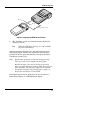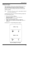
1
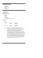
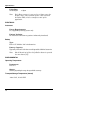
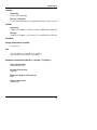
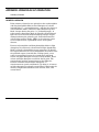
OPERATOR’S MANUAL
NPB-40
Handheld Pulse Oximeter
Caution: Federal law (U.S.) restricts this device to sale by or on the order
of a physician.
To contact Mallinckrodt’s representative: In the United States, call 1-800635.5267; outside of the United States, call your local Mallinckrodt
representative.
012 3
© 2001 Mallinckrodt Inc. All rights reserved. 060328B-0601
Nellcor Puritan Bennett Inc.
4280 Hacienda Drive
Pleasanton, CA 94588 USA
Telephone Toll Free 1.800.NELLCOR
Tyco Healthcare UK LTD
Fareham Road
Gosport
PO13 0AS
U.K.
Tel: 44.1329.224000
Nellcor Puritan Bennett Inc. is a wholly-owned subsidiary of Mallinckrodt
Inc. Nellcor and Nellcor Puritan Bennett are trademarks of Mallinckrodt Inc.
To obtain information about a warranty, if any, for this product, contact
Mallinckrodt Technical Services Department, or your local Mallinckrodt
representative.
The following are trademarks of Mallinckrodt Inc.: Durasensor, Oxiband,
Oxisensor, Oxisensor II, OxiCliq, and Dura-Y.
Covered by one or more of the following U.S. Patents and foreign equivalents:
4,621,643; 4,685,464; 4,700,708; and 4,770,179.
CONTENTS
Figures
Tables
Figures ...............................................................................
Tables ................................................................................
SAFETY INFORMATION .........................................................
General Safety Information ................................................
INTRODUCTION ......................................................................
Intended use ......................................................................
General Operating Principles and Conditions ...................
CONTROLS, INDICATORS, AND SYMBOLS .........................
Displays, Controls, Indicators, and Connectors ................
Other NPB-40 Symbols ......................................................
Description of Controls ......................................................
Function Keys ..............................................................
Status Icons .................................................................
Description of Visual Indicators and Displays ....................
Description of Audible Indicators .......................................
SETUP ......................................................................................
Unpacking and Inspection..................................................
Testing ...............................................................................
List of Components ............................................................
Optional Accessories ...................................................
Monitor Setup .....................................................................
Installing the Batteries..................................................
General ........................................................................
NELLCOR SENSORS ..............................................................
Selecting a Sensor .............................................................
Biocompatibility Testing ...............................................
Performance Considerations .............................................
START-UP AND USE...............................................................
Basic Operation .................................................................
Power-On Self-Test (POST) ........................................
Monitoring Mode ..........................................................
Pulse Search Mode .....................................................
Determining Software Version ...........................................
Silencing or Adjusting Pulse Beep Volume .......................
Turning Display Light (Backlight) On or Off .......................
Storing Event Data .............................................................
Printing Event Data ............................................................
iii
iii
1
1
3
3
3
5
5
7
8
8
8
9
10
11
11
11
11
11
12
12
13
15
15
16
16
19
19
20
21
22
23
23
23
23
24
iii
Contents
Preparing the NPB-40 for Printing ...............................
Single Event Report .....................................................
Multiple Event Report ..................................................
Printer and Printer Accessories ...................................
Sensor Disconnect Indicator ..............................................
Battery Operation...............................................................
Disposal of Device Components .......................................
Performance Considerations..............................................
Impact of Patient Conditions on Monitor Readings......
TROUBLESHOOTING AND MAINTENANCE .........................
Troubleshooting .................................................................
EMI Interference ................................................................
Obtaining Technical Assistance .........................................
Returning the NPB-40 .......................................................
Maintenance ......................................................................
Service .........................................................................
Cleaning.......................................................................
Periodic Safety Checks ......................................................
SPECIFICATIONS ...................................................................
Performance ......................................................................
Electrical ............................................................................
Environmental ....................................................................
Physical..............................................................................
APPENDIX: PRINCIPLES OF OPERATION ............................
Oximetry Overview.............................................................
Automatic Calibration...................................................
Functional Versus Fractional Saturation......................
Measured Versus Calculated Saturation.....................
24
26
27
28
28
28
29
30
30
31
31
33
34
34
35
35
35
35
37
37
38
38
39
41
41
42
42
43
FIGURES
Figure 1: NPB-40 Front/Side View ...........................................
Figure 2: NPB-40 Front Panel Display......................................
Figure 3: NPB-40 Rear View ....................................................
Figure 4: NPB-40 Top View ......................................................
Figure 5: Installing Batteries .....................................................
Figure 6: Aligning the NPB-40 and Printer ................................
Figure 7: Single Event Report...................................................
Figure 8: Multiple Event Report ................................................
Figure 9: Oxyhemoglobin Dissociation Curve...........................
5
6
6
7
12
25
26
27
43
TABLES
Table 1: Nellcor Sensors........................................................... 15
iv
SAFETY INFORMATION
General Safety Information
GENERAL SAFETY INFORMATION
This section contains important safety information related to
general use of the NPB-40 monitor. Other important safety
information appears throughout the manual in sections that
relate specifically to the precautionary information. Be sure to
read all text surrounding all precautionary information.
Important! Before use, carefully read this manual,
accessory directions for use, all precautionary
information in boldface type, and specifications.
WARNING: The NPB-40 is a prescription device and is to
be operated by qualified personnel only.
WARNING: The NPB-40 is not equipped with alarms.
The monitor is for attended monitoring only, and must
be used under the direct supervision of a qualified
health care provider.
WARNING: Explosion hazard. Do not use the NPB-40
pulse oximeter in the presence of flammable
anesthetics.
WARNING: The cover should be removed only by
qualified service personnel. There are no userserviceable parts inside.
WARNING: To ensure accurate performance and
prevent device failure, do not expose the NPB-40 to
extreme moisture, such as rain.
Caution: The NPB-40 is intended only as an adjunct in
patient assessment. It must be used in conjunction with
clinical signs and symptoms.
WARNING: Pulse oximetry readings and pulse signal
can be affected by certain ambient environmental
conditions, sensor application errors, and certain
patient conditions.
1
Safety Information
To ensure accurate readings, consider the environmental
conditions that are present and the condition of the patient.
See the appropriate sections of the manual for specific safety
information related to these conditions.
WARNING: If you are uncertain about the accuracy of
any measurement, check the patient’s vital signs by
alternate means, then make sure the monitor is
functioning correctly.
2
INTRODUCTION
Intended Use
General Operating Principles and Conditions
INTENDED USE
The Nellcor NPB-40 handheld pulse oximeter is intended for
noninvasive spot-check measurement of functional oxygen
saturation of arterial hemoglobin (SpO2 ), and pulse rate
(measured by SpO 2 sensor).
The monitor is intended for use on adult, pediatric, and
neonatal patients. It can be used in mobile environments when
protected from excessive moisture such as direct rainfall.
Caution: The NPB-40 is intended only as an adjunct in
patient assessment. It must be used in conjunction with
clinical signs and symptoms.
WARNING: The NPB-40 is not equipped with alarms.
The monitor is for attended monitoring only, and must
be used under the direct supervision of a qualified
health care provider.
WARNING: Do not use the NPB-40 or Nellcor sensors
during magnetic resonance imaging (MRI) scanning.
Induced current could potentially cause burns. The
NPB-40 may affect the MRI image; the MRI unit may
affect the accuracy of oximetry measurements.
Caution: The NPB-40 may be used during defibrillation,
but the readings may be inaccurate for a short time.
The battery-operated NPB-40 is designed to send previously
stored patient data to an external Hewlett-Packard HP82240B
printer, available from Mallinckrodt.
GENERAL OPERATING PRINCIPLES AND CONDITIONS
The NPB-40 uses pulse oximetry to measure oxygen saturation
in the blood. Pulse oximetry works by applying a sensor to
pulsating arteriolar vascular bed, such as a finger or toe. The
sensor contains a dual light source and a photodetector.
3
Introduction
Bone, tissue, pigmentation, and venous vessels normally
absorb a constant amount of light over time. The arteriolar bed
normally pulsates and absorbs variable amounts of light during
the pulsations. The ratio of light absorbed is translated in an
oxygen saturation measurement (SpO 2).
Because a measurement of SpO2 is dependent on light from the
sensor, excessive ambient light can interfere with this
measurement.
WARNING: Pulse oximetry readings and pulse signal
can be affected by certain ambient environmental
conditions, sensor application errors, and certain
patient conditions.
Specific information about ambient environmental conditions,
sensor application, and patient conditions, is contained
throughout this manual.
4
CONTROLS, INDICATORS, AND SYMBOLS
Displays, Controls, Indicators, and Connectors
Other NPB-40 Symbols
Description of Controls
Description of Visible Indicators and Displays
Description of Audible Indicators
DISPLAYS, CONTROLS, INDICATORS, AND CONNECTORS
Figures 1 through 4 show the front, side, rear, and top views of
the NPB-40 and identify displays, controls, and connectors.
1
2
3
4
1. Function keys
2. Status icons
3. Digital display
4. Sensor port
Figure 1: NPB-40 Front/Side View
5
Controls, Indicators, and Symbols
1
15
2
14
13
12
3
4
11
6
5
10
1.
2.
3.
4.
5.
6.
7.
8.
9
8
7
Pulse Amplitude indicator
Pulse Rate display
Pulse Search indicator
Low Battery indicator
Sensor Disconnect indicator
Power On/Off key
(Shift+) Beep On/Off key
Display Light key
9.
10.
11.
12.
13.
14.
15.
(Shift+) Print key
Store Data key
Shift Key
Store Data icon
Shift Key icon
Print icon
SpO2% display
Figure 2: NPB-40 Front Panel Display
2
1
3
1. Sound ports
2. Battery compartment latch
3. Battery compartment door
Figure 3: NPB-40 Rear View
6
Controls, Indicators, and Symbols
1. Printer infrared window
1
Figure 4: NPB-40 Top View
OTHER NPB-40 SYMBOLS
Attention: See Instructions for Use
Percent oxygen saturation
/min
Pulse rate, measured in beats per minute (bpm)
Type BF equipment
Alkaline “AA” size, 1.5 V batteries
7
Controls, Indicators, and Symbols
DESCRIPTION OF CONTROLS
Function Keys
Power On/Off key. This key is used to turn the
NPB-40 monitor on or off.
Shift key. When pressed in conjunction with
another Function key, the Shift key changes the
function of the other key to that designated by its
upper icon.
Combo 1 key. When pressed by itself, this key
functions as the Store Data key (lower icon). It
stores the currently displayed patient data for
printing at a later time.
Pressing the Shift key before pressing the
Combo1 key, changes the function to that of a
Print key (upper icon). This action sends patient
data to an active, properly aligned, HewlettPackard printer, to generate a printed report.
Combo 2 key. When pressed by itself, this key
functions as the Display Light key (lower icon).
It turns the display backlight on or off.
Pressing the Shift key before pressing the Combo
2 key, changes the function that of a Beep On/Off
key (upper icon). This action silences or adjusts
the pulse beep volume (see “Silencing or
Adjusting Beep Volume” in the Start-Up and Use
section of this manual).
Status Icons
Shift icon lights when the Shift key function
is in use.
Store Data icon lights when the Store Data
function is in use. While the icon is lit, either
during data storage or printing, the event number
is shown on the display.
8
Controls, Indicators, and Symbols
Print icon lights when the Print function is in
use. Note: while printing, the monitor does not
measure SpO2 .
The Pulse Search icon lights prior to initial
acquisition of a pulse signal, and during Pulse
Search mode.
The Low Battery icon flashes when 45 minutes or
less battery capacity remains (with disposable
batteries). The icon flashes at least once per
second. Refer to “Battery Operation” in the StartUp and Use section for a discussion regarding use
of disposable and rechargeable batteries.
The Sensor Disconnect icon lights when the
NPB-40 does not detect the connection of an
SpO 2 sensor to the monitor.
DESCRIPTION OF VISUAL INDICATORS AND DISPLAYS
The SpO2 % display show hemoglobin oxygen
saturation level. It is updated with each pulse.
Synchronous with each pulse, the monitor beeps.
If the SpO 2 level drops by more than 2%, the
monitor will emit a double-beep tone.
The Pulse Amplitude indicator is a 10-segment
display that shows the relative pulse amplitude.
As the detected pulse becomes stronger, more
contiguous segments light with each pulse.
The digital Pulse Rate display shows the pulse
rate in beats per minute. It is updated with each
pulse.
9
Controls, Indicators, and Symbols
DESCRIPTION OF AUDIBLE INDICATORS
Following are audible indicators for which there are no
accompanying symbols, keys, or visual indicators.
WARNING: The NPB-40 is not equipped with alarms.
The monitor is for attended monitoring only, and must
be used under the direct observation of a qualified
health care provider.
10
Power-Up Self-Test pass
One 2-second tone
No sensor connected at startup (or sensor disconnected)
Error tone (dual-pitch tone)
for 3 seconds
SpO 2 drop of more than 2%
1 double-beep tone
No Pulse detected for
30 seconds after power-up
2 triple-beeps, then NPB-40
turns itself off
Pulse acquired, then lost. No
pulse detected for 15 minutes,
and event memory is empty.
2 triple-beeps, then NPB-40
turns itself off
Pulse acquired, then lost. No
pulse detected for 60 minutes,
and event memory is not
empty.
1 triple-beep every
10 seconds
Low Battery
1 triple-beep tone at
3-minute intervals
Impending Dead Battery
2 triple-beep tones, then
NPB-40 turns itself off
SETUP
Unpacking and Inspection
Testing
List of Components
Monitor Setup
UNPACKING AND INSPECTION
Notify the carrier if the shipping carton is damaged. Unpack
the NPB-40 and components. If anything is missing or
damaged, contact Mallinckrodt Technical Services Department
or your local Mallinckrodt representative.
TESTING
Before using the NPB-40 in a clinical setting, verify that the
monitor functions properly by following the instructions in the
Start-Up and Use section of this manual.
LIST OF COMPONENTS
1
4
1
1
1
Nellcor NPB-40 handheld pulse oximeter
Alkaline “AA” size, 1.5 V batteries
Durasensor ® oxygen transducer, model DS-100A
Operator’s manual
Quick Guide adhesive label
Optional Accessories
The following items are available from Mallinckrodt for use
with this monitor:
•
•
•
•
•
Protective “Boot”
Rain Jacket
Carrying Case
Hewlett-Packard printer, model HP82240B
Hewlett-Packard printer paper
11
Setup
MONITOR SETUP
Installing the Batteries
1.
Pull the battery compartment latch downward, toward the
bottom of the monitor, and remove the battery access door.
2.
Install four “AA” size batteries, oriented as shown in
Figure 5. Replace the battery access door.
Note:
Install the negative end of each battery first,
compressing the battery terminal spring until the
positive terminal clears the positive spring, and
pressing the battery downward, into place.
To remove the batteries, reverse the installation
process, removing the positive end of each battery
first.
Refer to “Battery Operation” in the Start-Up and Use section of
this manual for important information including the types of
batteries to be used with the NPB-40, and precautionary
information.
Figure 5: Installing Batteries
12
Setup
General
WARNING: Explosion hazard. Do not use the NPB-40
handheld pulse oximeter in the presence of flammable
anesthetics.
WARNING: To ensure patient safety, do not place the
monitor in any position that might cause it to fall on the
patient.
WARNING: As with all medical equipment, carefully
route patient cabling to reduce the possibility of patient
entanglement or strangulation.
WARNING: To ensure accurate performance and
prevent device failure, do not expose the NPB-40 to
extreme moisture such as rain.
13
(This page intentionally left blank)
NELLCOR SENSORS
Selecting a Sensor
Performance Considerations
SELECTING A SENSOR
WARNING: Before use, carefully read the sensor
directions for use, including all warnings, cautions, and
instructions.
WARNING: Do not use a damaged sensor. Do not use a
sensor with exposed optical components.
WARNING; Use only Nellcor sensors for SpO2
measurements. Other sensors may cause improper NPB40 performance.
When selecting a sensor, consider the patient’s weight and
activity level, the adequacy of perfusion, the available sensor
sites, the need for sterility, and the anticipated duration of
monitoring. For more information, refer to Table 1 or contact
your local Mallinckrodt representative.
Table 1: Nellcor Sensors
Sensor
Model
Patient Size
Oxisensor® and Oxisensor II oxygen
transducers (Sterile, single-use only)
N-25
I-20
D-20
D-25(L)
R-15
<3 or >40 kg
3–20 kg
10–50 kg
>30 kg
>50 kg
Oxiband® oxygen transducers (Reusable
with disposable nonsterile adhesive)
OXI-A/N
OXI-P/I
<3 or >40 kg
3–40 kg
Durasensor® oxygen transducer
(Reusable, nonsterile)
DS-100A
>40 kg
Nellcor reflectance oxygen transducer
(Reusable, nonsterile)
RS-10
>40 kg
Dura-Y ® m u l t i s i t e oxygen
transducer (Reusable, nonsterile)
D-YS
>1 kg
OxiCliq® oxygen transducers (Sterile,
single-use only)
P
N
I
A
10 to 50 kg
<3 or >40 kg
3 to 20 kg
>30 kg
15
Nellcor Puritan Bennett Sensors
Biocompatibility Testing
Biocompatibility testing has been conducted on Nellcor sensors
in compliance with ISO 10993-1, Biological Evaluation of
Medical Devices, Part 1: Evaluation and Testing. The sensors
have passed the recommended biocompatibility testing and are,
therefore, in compliance with ISO 10993-1.
PERFORMANCE CONSIDERATIONS
WARNING: Pulse oximetry readings and pulse signal
can be affected by certain ambient environmental
conditions, sensor application errors, and certain
patient conditions.
Inaccurate measurements can be caused by:
•
incorrect application of the sensor
•
placement of the sensor on an extremity with a blood
pressure cuff, arterial catheter, or intravascular line
•
ambient light
•
patient movement
Loss of pulse signal can occur for the following reasons:
•
the sensor is too tight
•
a blood pressure cuff is inflated on the same extremity as
the one with the sensor attached
•
there is arterial occlusion proximal to the sensor
Use only Nellcor sensors and sensor cables. Select an
appropriate sensor, apply it as directed, and observe all
warnings and cautions presented in the directions for use
accompanying the sensor. Clean and remove any substances
such as nail polish from the application site. Periodically check
to see that the sensor remains properly positioned on the
patient.
16
Nellcor Puritan Bennett Sensors
WARNING: Tissue damage can be caused by incorrect
application or duration of use of an SpO 2 sensor. Inspect
the sensor site as directed in the sensor directions for
use.
High ambient light sources such as surgical lights (especially
those with a xenon light source), bilirubin lamps, fluorescent
lights, infrared heating lamps, and direct sunlight can interfere
with the performance of an SpO 2 sensor. To prevent
interference from ambient light, ensure the sensor is properly
applied, and cover the sensor site with opaque material.
Note:
Failure to take this precaution in high ambient light
conditions may result in inaccurate measurements.
If patient movement presents a problem, try one or more of the
following remedies to correct the problem.
•
•
•
•
Verify that the sensor is properly and securely applied.
Move the sensor to a less active site.
Use an adhesive sensor that tolerates some patient motion.
Use a new sensor with fresh adhesive backing.
If poor perfusion affects performance, consider using the
Oxisensor R-15 sensor; it obtains measurements from the nasal
septal anterior ethmoid artery, an artery supplied by the
internal carotid. This sensor may obtain measurements when
peripheral perfusion is relatively poor. For low peripheral
perfusion, consider using the Nellcor RS-10 sensor, which is
applied to the forehead or temple, sites that may be spared
during peripheral vasoconstriction.
Note:
The preceding section pertains to patient and
environmental conditions that can be addressed by
sensor selection and application. For information
regarding the impact of other patient and
environmental conditions on oximeter performance, see
“Performance Considerations” in the Start-Up and Use
section.
17
(This page intentionally left blank)
START-UP AND USE
Basic Operation
Determining Software Version
Silencing or Adjusting Pulse Beep Volume
Turning Display Light (Backlight) On or Off
Storing Event Data
Printing Event Data
Sensor Disconnect Indicator
Battery Operation
Disposal of Device Components
Performance Considerations
BASIC OPERATION
WARNING: The NPB-40 is a prescription device and is to
be operated by qualified personnel only.
WARNING: Do not lift the monitor by the sensor cable
because the cable could disconnect from the monitor,
causing the monitor to drop on the patient.
Caution: The NPB-40 is intended only as an adjunct in
patient assessment. It must be used in conjunction with
clinical signs and symptoms.
Important! Prior to using the NPB-40, carefully read
this manual, accessory directions for use, all
precautionary information in boldface type, and all
specifications.
Before you use the NPB-40, you must verify that the monitor is
working properly and is safe to use. Proper working condition
can be verified by successful completion of the power-on selftest described in the following steps, and by following the
instructions contained in “Monitoring Mode” in this section.
Note:
Before using the NPB-40, remove the plastic protective
sheet that covers the display. This sheet is only on the
display to protect it during shipping. Leaving it on
during monitoring could make it difficult to read
displayed measurements.
19
Start-Up and Use
Power-On Self-Test (POST)
Caution: Do not connect anything other than an SpO 2
sensor to the sensor port (for example, do not attempt to
connect a PC to the NPB-40).
Note:
1.
It is recommended that a sensor be connected prior to
start-up. If no sensor is connected at start-up, an error
tone sounds for approximately 3 seconds.
Plug an appropriate Nellcor sensor firmly into the sensor
port, and apply the sensor to the patient as described in
the sensor directions for use. If needed, use a Nellcor
sensor extension cable, model EC-4 or EC-8.
Caution: During the self-test (immediately after powerup), confirm that all display segments and icons light.
2.
Turn on the NPB-40 by pressing the On/Off key. The
monitor automatically conducts a power-on self-test, which
tests its circuitry and lights the entire numeric display.
3.
While performing the power-on self-test (POST), the POST
Display appears for approximately 3-5 seconds. During this
time:
•
•
•
•
All icons light
All segments of all numeric digits light
All segments of the Pulse Amplitude Display light
Display backlight is turned on.
During POST, check to ensure that all display icons and
numeric segments light.
If any icon or numeric segment does not light, do not use
the monitor. Instead, contact Mallinckrodt Technical
Services Department, or your local Mallinckrodt
representative.
4.
20
If the NPB-40 detects an internal problem during POST,
an error tone sounds and the monitor displays an Error
Code and corresponding number (see Troubleshooting
section for error codes and necessary action that should be
taken).
Start-Up and Use
5.
Upon successful completion of the POST, the NPB-40
sounds a 2-second tone indicating that the monitor has
passed the test.
6.
Once the power-on self-test is complete, and the monitor
has displayed its software version (refer to discussion
“Determining Software Version” in this section), the
NPB-40 attempts to detect a valid pulse.
If a valid pulse is not detected within 30 seconds of turning
on the monitor, the NPB-40 sounds two triple beeps and
then automatically shuts off to conserve battery life.
If a valid pulse is detected, the NPB-40 enters Monitoring
Mode.
Monitoring Mode
In Monitoring Mode, the NPB-40 is either taking an SpO2
measurement, storing event data, or printing data that has
been stored in its memory.
While taking an SpO2 measurement, the monitor displays
SpO 2 and pulse rate readings with each pulse beat. The
constant-pitch beep sounds once for each pulse, and the Pulse
Amplitude indicator visually displays pulse strength at the
sensor site.
Note:
Verify that indicators, icons, display information, and
audible sounds are all operational, indicating that the
monitor is functioning. Each valid keypress should
generate an appropriate action.
If any actions do not seem appropriate, do not use the
monitor. Instead, contact Mallinckrodt Technical
Services Department or your local Mallinckrodt
representative.
In Monitoring Mode, if the acquired pulse is lost, the monitor
enters Pulse Search Mode.
21
Start-Up and Use
Pulse Search Mode
During Pulse Search Mode, the monitor attempts to detect a
pulse from which to take a measurement.
Note:
Pulse Search is a normal function of the monitor, and
entering this mode is not necessarily indicative of a lost
patient pulse.
At Initial Power-Up
Immediately after the monitor is turned on and the power-on
self-test is completed and the NPB-40 displays its software
version number, the monitor enters Pulse Search Mode and the
Pulse Search icon lights. The display reads zeroes while it
searches for a valid pulse.
If a valid pulse is detected within 30 seconds of entering this
mode at initial start-up, the NPB-40 enters Monitoring Mode.
If a valid pulse is not detected within 30 seconds of entering
Pulse Search Mode after start-up, the monitor sounds two
triple beeps, and then automatically shuts off.
After Taking Measurements
If a pulse was acquired previously and then lost, the NPB-40
enters Pulse Search Mode, and the Pulse Search icon lights.
The display shows the last detected readings while it searches
for a valid pulse. When it considers the pulse “lost,” it displays
zeroes and continues its search.
If a valid pulse is again detected within 15 minutes of entering
Pulse Search, the NPB-40 immediately reenters Monitoring
Mode.
If a valid pulse is not detected within 15 minutes of entering
Pulse Search Mode, the NPB-40 sounds two triple beeps and
turns itself off, provided no event data has been stored since the
monitor was turned on. If patient event data is stored, the
monitor will remain on and, after 60 minutes, will triple-beep
at 10-second intervals as a reminder.
Once a valid pulse is again acquired in this mode, the
instrument enters Monitoring Mode.
22
Start-Up and Use
DETERMINING SOFTWARE VERSION
Immediately following the successful completion of the poweron self-test, the monitor displays the software version
contained in the monitor.
Note:
This software version number is often needed when
calling Mallinckrodt Technical Services Department or
your local Mallinckrodt representative for technical
assistance.
After displaying the software version for approximately
3-5 seconds, the Pulse Search icon lights, indicating that the
NPB-40 is in operation.
SILENCING OR ADJUSTING PULSE BEEP VOLUME
At start-up, the pulse beep is ON, with the volume set at
HIGH. By pressing the Shift key and then the Display
Light/Sound (Combo 2) function key, you may cycle the NPB-40
pulse beep tone from HIGH volume through OFF, LOW
volume, and then back to HIGH volume.
While using the NPB-40, do not cover the holes located in the
rear of the monitor. These allow the audible alert sounds (error
tones) and pulse beep tones to exit the monitor.
TURNING DISPLAY LIGHT (BACKLIGHT) ON OR OFF
The NPB-40 has a display backlight that may be turned on and
off manually. To do this, press the Display Light/Sound (Combo
2) function key by itself (do not press the Shift key).
When the display backlight is on, it remains on for
approximately 10 minutes, then automatically shuts off to
conserve battery use.
STORING EVENT DATA
The NPB-40 pulse oximeter contains an internal memory that
can store 50 patient data records for later printing. To activate
the Store Data function:
1.
While in Monitoring Mode, press the Store Data key. The
monitor displays the Store Data icon along with a number
that identifies the entry. It then copies the current SpO2
and pulse rate into that memory location.
The Data Storage Display (indicating the ID number of the
entry) remains on the screen for approximately 3 seconds
from the time the Store Data key was pressed.
23
Start-Up and Use
2.
When the patient data storage is completed, the monitor
returns to the mode it was in previously.
Note:
When the Store Data key is pressed and there is
NO empty event memory location available, the
monitor displays the last ID number assigned (50),
displays the flashing Store Data icon, and sounds
an error tone for 3 seconds.
Events are retained in the NPB-40 memory while the monitor
remains on and are cleared when the monitor is turned off or
powers itself off. If they are cleared, the events will not be
available for later printing.
Note:
The instrument will clear all stored data if the batteries
are removed.
PRINTING EVENT DATA
The NPB-40 has the ability to print event data when used with a
Hewlett-Packard printer, model HP82240B, which is available from
Mallinckrodt.
Note:
Read the entire user’s manual for the Hewlett-Packard
HP82240B printer prior to using the printer with the
NPB-40.
Preparing the NPB-40 for Printing
In order to print event data, the monitor and printer must be
turned on, and the monitor and printer must be aligned as
follows.
1.
24
Place the printer and monitor on a flat, stable surface,
oriented as shown in Figure 6.
Start-Up and Use
0°– 5°
0°– 5°
1"– 2" (2.5 – 5.1 cm.)
Figure 6: Aligning the NPB-40 and Printer
2.
The “windows” on the two instruments must be directly
aligned, as shown.
Note:
While the NPB-40 is printing, it is not available
for patient monitoring.
After the monitor and printer are ON and aligned properly,
data that has been stored in the monitor’s memory may be
printed. To do this, press the Shift key, then press the Store
Data/Print (Combo 1) key.
Note:
Do not move the printer or monitor during printing.
This can result in an incomplete printed report.
Should you move either device during the printing
process enough to disrupt printing, allow the print cycle
to be completed. You may then reposition the monitor
and printer and begin the printing process again, as
long as the monitor has remained ON.
Event data reports may be printed in one of two formats: a
Single Event Report, or a Multiple Event Report.
25
Start-Up and Use
Single Event Report
To initiate a single event report, the sensor must be on the
patients finger and the NPB-40 must be displaying readings.
When there are no monitoring events stored in memory,
pressing the Shift + Print key will result in the monitor
generating the Print Display and sending a Single Event
Report to the printer. This report contains the current oxygen
saturation and pulse rate information.
The format for the Single Event Report follows:
•
•
•
•
Name of the monitor (NPB-40)
Notes Line (approximately 1/2 inch of space for
handwritten notes)
Elapsed time
“SpO 2” and “BPM” (pulse rate) readings including
minimum, maximum, and average values.
See Figure 7 for a sample Single Event Report.
Figure 7: Single Event Report
26
Start-Up and Use
Multiple Event Report
When the Shift + Print keys are pressed and there are one or
more monitoring events stored in memory, the monitor
generates the Printing Display and sends a Multiple Event
Report to the printer, starting with the first event that was
stored in memory.
Note:
This mode will not print out the current SpO2 and pulse
rate, only the stored events.
The Multiple Event Report contains the following components
for each monitoring event:
•
•
•
•
•
Name of the monitor (NPB-40)
Notes Line (approximately 1/2 inch of space for
handwritten notes)
Event ID (storage record number)
“SpO 2” and the stored SpO 2 value on a single line
“BPM” (pulse rate) and the stored Pulse Rate value on a
single line
See Figure 8 for a sample Multiple Event Report.
Figure 8: Multiple Event Report
27
Start-Up and Use
Printer and Printer Accessories
The Hewlett-Packard printer model HP82240B, the printer AC
adapter, and thermal printer paper refills are available from
Mallinckrodt.
SENSOR DISCONNECT INDICATOR
When the NPB-40 is in Monitoring or Pulse Search Modes and
it detects an invalid sensor connection, the Sensor Disconnect
indicator flashes and the monitor generates an error tone for
3 seconds. If a valid sensor connection is not made within
30 seconds, the monitor sounds two triple-beeps, and then
turns itself off.
If a valid sensor connection is made within 30 seconds, the
monitor begins a new Pulse Search.
Note:
In Monitoring Mode, if the acquired pulse is lost, the
monitor enters Pulse Search Mode. Important! This
transition does not generate an audible alert
upon loss of pulse.
BATTERY OPERATION
Caution: Check the batteries periodically for corrosion.
Replace batteries if corrosion is present, otherwise
damage to the monitor may occur.
Caution: Do not use lithium batteries with the NPB-40.
Lithium batteries will damage the monitor.
The NPB-40 pulse oximeter is powered by four alkaline “AA”
cell batteries. Typically, a fresh set of disposable “AA” batteries
will provide 19 hours of continuous monitoring (with the
display backlight OFF).
28
Note:
Not all brands of off-the-shelf alkaline batteries provide
the same battery life.
Note:
Do not mix alkaline “AA” batteries with rechargeable
batteries. When replacing batteries, replace with four
fresh (new) batteries. Do not mix used and new
batteries.
Start-Up and Use
Note:
If the batteries are low when the monitor is turned on,
the Low Battery indicator will not flash until the
instrument enters normal operation.
When 45 minutes or less of disposable, alkaline battery life
remains, the Low Battery indicator lights and a triple-beep
tone occurs at 3-minute intervals.
Rechargeable alkaline batteries may be used with the NPB-40.
It must be noted, however, the battery life per charge will be
less than that typical for disposable batteries. In addition, each
subsequent charge of the rechargeables will yield shorter
battery life cycles.
For example, a typical set of rechargeable alkaline batteries
will usually yield 10 hours of continuous monitoring of the
NPB-40, but each recharge will provide a shorter monitoring
time, until the average battery life cycle is about 3.5 hours per
charge.
Note:
Because of this decrease per charge cycle, the Low
Battery Indicator and battery life specification quoted
for disposable alkalines will not apply to rechargeables.
Regardless of what battery type is used, when the remaining
battery life is insufficient to operate the monitor within its
specifications, the NPB-40 sounds two triple-beeps and turns
itself off.
Caution: Remove the batteries from the NPB-40 prior to
storing the monitor for an extended period of time.
DISPOSAL OF DEVICE COMPONENTS
Caution: Follow local governing ordinances and
recycling instructions regarding disposal or recycling of
device components, including batteries.
29
Start-Up and Use
PERFORMANCE CONSIDERATIONS
Impact of Patient Conditions on Monitor Readings
Certain patient conditions can affect the measurements of the
NPB-40 and cause the loss of the pulse signal.
WARNING: Pulse oximetry readings and pulse signals
can be affected by certain ambient environmental
conditions, sensor application errors, and certain
patient conditions.
Inaccurate measurements can be caused by:
•
•
•
•
•
excessive patient movement
venous pulsations
intravascular dyes, such as indocyanine green or
methylene blue
significant levels of dysfunctional hemoglobins
defibrillation
Ambient environmental conditions and sensor application
errors, which can affect pulse oximetry readings, are discussed
in the Nellcor Sensors section of this manual and in the sensor
directions for use.
The effects of electromagnetic interference on oximetry
readings is discussed in the Troubleshooting and Maintenance
section of this manual.
30
TROUBLESHOOTING AND MAINTENANCE
Troubleshooting
EMI Interference
Obtaining Technical Assistance
Returning the NPB-40
Maintenance
Periodic Safety Checks
TROUBLESHOOTING
WARNING: If you are uncertain about the accuracy of
any measurement, check the patient’s vital signs by
alternate means; then make sure the monitor is
functioning correctly.
WARNING: The cover should be removed only by
qualified service personnel. There are no user-serviceable parts inside.
If you experience a problem while using the NPB-40 and are
unable to correct it, contact qualified service personnel or
Mallinckrodt’s representative. The NPB-40 service manual,
which is for use by qualified service personnel, provides
additional troubleshooting information.
Following is a list of possible errors and suggestions for
correcting them.
1.
There is no response to the Power On/Off key.
•
2.
The batteries may be missing, discharged, or oriented
incorrectly.
One or more display segments or indicators do not
light during the power-on self-test.
•
Do not use the NPB-40; contact qualified service
personnel or your local Mallinckrodt representative.
31
Troubleshooting and Maintenance
3.
4.
32
The Pulse Search indicator is lit for more than
10 seconds.
•
Check the sensor directions for use to determine if an
appropriate sensor is being used and if it is applied
properly. Check sensor and extension cable
connections. Test the sensor on someone else. Try
another sensor or extension cable.
•
Perfusion may be too low for the NPB-40 to track the
pulse. Check the patient. Test the instrument on
someone else. Change the sensor site. Try another type
of sensor.
•
Excessive patient motion may be preventing the
NPB-40 from tracking the pulse. Keep the patient still,
if possible. Verify that the sensor is securely applied,
and replace it if necessary. Change the sensor site. Use
a type of sensor that tolerates more patient movement
(for example, an adhesive sensor).
•
The sensor may be too tight, there may be excessive
ambient light, or the sensor may be on an extremity
with a blood pressure cuff, arterial catheter, or
intravascular line. Reposition sensor, as necessary.
•
Excessive environmental motion or electromagnetic
interference may be preventing the NPB-40 from
tracking the pulse. Remove the source of interference
or try to stabilize the environment, or do both.
The Pulse Search indicator lights after successful
measurements have been made.
•
Check the patient.
•
Perfusion may be too low for the NPB-40 to track the
pulse. Test the instrument on someone else. Change
the sensor site. Try another type of sensor.
•
Excessive patient motion may be preventing the
NPB-40 from tracking the pulse. Verify that the sensor
is securely applied and replace it if necessary. Change
the sensor site. Use a type of sensor that tolerates
more patient movement (for example, an adhesive
sensor).
Troubleshooting and Maintenance
5.
•
The sensor may be too tight, there may be excessive
ambient light, or the sensor may be on an extremity
with a blood pressure cuff, arterial catheter, or
intravascular line. Reposition sensor, as necessary.
•
Excessive environmental motion or electromagnetic
interference may be preventing the NPB-40 from
tracking the pulse. Remove the source of interference
or try to stabilize the environment, or do both.
A number followed by EEE appears on the display.
•
Record the number and provide that information to
qualified service personnel or your local Mallinckrodt
representative.
EMI INTERFERENCE
Caution: This device has been tested and found to
comply with the limits for medical devices to the IEC
601-1-2:1993, EN60601-1-2;1994, Medical Device Directive
93/42/EEC. These limits are designed to provide
reasonable protection against harmful interference in a
typical medical installation. However, because of the
proliferation of radio-frequency transmitting equipment
and other sources of electrical noise in the health-care
and home environments (for example, cellular phones,
mobile two-way radios, electrical appliances), it is
possible that high levels of such interference due to
close proximity or strength of a source, may result in
disruption of performance of this device.
The NPB-40 is designed for use in environments in which the
pulse can be obscured by electromagnetic interference. During
such interference, measurements may seem inappropriate or
the monitor may not seem to operate correctly.
The NPB-40 generates, uses, and can radiate radio frequency
energy and, if not installed and used in accordance with these
instructions, may cause harmful interference with other
devices in the vicinity. Disruption may be evidenced by erratic
readings, cessation of operation, or other incorrect functioning.
If this occurs, the site of use should be surveyed to determine
the source of this disruption, and actions taken to eliminate the
source:
33
Troubleshooting and Maintenance
•
Turn equipment in the vicinity off and on to isolate the
offending equipment.
•
Reorient or relocate the other receiving device.
•
Increase the separation between the interfering equipment
and this equipment.
If assistance is required, contact Mallinckrodt Technical
Services Department or your local Mallinckrodt representative.
OBTAINING TECHNICAL ASSISTANCE
For technical information and assistance, or to order parts or a
service manual, contact Mallinckrodt Technical Services
Department or your local Mallinckrodt representative. The
service manual includes block diagrams and a parts list
required by qualified personnel when servicing the NPB-40.
When calling Mallinckrodt Technical Services Department or
your local Mallinckrodt representative, you may be asked to
tell the representative the software version number of your
NPB-40.
The software version appears on the display screen
immediately after the power-on self-test is completed. Write
the number down and have it available whenever requesting
technical assistance.
RETURNING THE NPB-40
Contact Mallinckrodt Technical Services Department or your
local Mallinckrodt representative for shipping instructions
including a Returned Goods Authorization number. Remove
the batteries for shipping, and unplug the sensor. It is not
necessary to return the sensor. Pack the NPB-40 in its original
shipping carton. If the original carton is not available, use a
suitable carton with appropriate packing material to protect it
during shipping.
Return the NPB-40 by any shipping method that provides proof
of delivery.
34
Troubleshooting and Maintenance
MAINTENANCE
Service
WARNING: The cover should be removed only by
qualified service personnel. There are no user-serviceable parts inside.
The NPB-40 requires no routine service or calibration. If
service is necessary, contact qualified service personnel or your
local Mallinckrodt representative.
Cleaning
Caution: Do not allow any liquid to come in contact with
the NPB-40, its accessories, connectors, switches or
openings in the chassis.
To clean the NPB-40, dampen a cloth with a commercial,
nonabrasive cleaner, and lightly wipe the surfaces of the
monitor. Do not spray or pour liquid on the instrument or
accessories.
Before attempting to clean an SpO 2 sensor, first refer to the
directions for use enclosed with the sensor. Each sensor model
has cleaning instructions specific to that sensor.
PERIODIC SAFETY CHECKS
The following safety checks should be performed every
24 months by a qualified person who has adequate training,
knowledge, and practical experience to perform these tests.
•
Inspect the equipment for mechanical and functional
damage.
•
Inspect the safety relevant labels for legibility.
•
Verify that the device functions properly as described in
this operator’s manual.
The data should be recorded in an equipment log. If the device
is not functioning properly or fails any of the above tests, do not
attempt to repair the device. Please return the device to the
manufacturer or to your distributor for any required repairs.
35
(This page intentionally left blank)
SPECIFICATIONS
Performance
Electrical
Environmental
Physical
PERFORMANCE
Measurement Range
SpO 2
0–100%
Pulse Rate
20–250 beats per minute (bpm)
Accuracy
SpO 2
Adults
Neonates
Note:
70–100%
0–69%
±2 digits
unspecified
70–100%
0–69%
±3 digits
unspecified
Accuracies are expressed as plus or minus “X” digits
(oxygen saturation percentage points) between
saturations of 70–100%. This variation equals plus or
minus one standard deviation (1SD), which
encompasses 68% of the population. All accuracy
specifications are based on testing the subject monitor
on healthy adult volunteers in induced hypoxia studies
across the specified range. Adult accuracy is determined
with Oxisensor II D-25 sensors. Neonatal accuracy is
determined with Oxisensor II N-25 sensors. In addition,
the neonatal accuracy specification is adjusted to take
into account the theoretical effect of fetal hemoglobin in
neonatal blood on oximetry measurements.
37
Specifications
Pulse Rate
20–250 bpm
Note:
±3 bpm
Pulse Rate accuracy is expressed as ±3 bpm across the
display range. This variation equals ± one standard
deviation (1SD), which encompasses 68% of the
population.
ELECTRICAL
Instrument
Power Requirements
6V, supplied by battery-power only
Patient Isolation
No electrical connection to patient (inherently insulated)
Battery
Type
Four 1.5V alkaline “AA” size batteries
Battery Capacity
Typically 19 hours with four new disposable alkaline batteries
Note:
Not all brands of off-the-shelf alkaline batteries provide
the same battery life.
ENVIRONMENTAL
Operating Temperature
Instrument
0 to 55°C
Sensor
Within physiologic range for specified accuracy
Transport/Storage Temperature (boxed)
-40 to 70°C, 15-95% RH
38
Specifications
Humidity
Operating
15-95% noncondensing
Storage (unboxed)
15-95% noncondensing over temperature range of -20° C to 60° C
Altitude
Operating
-1280 ft. to 12,000 ft. (-390 m to 3,658 m) [1060 hPa to 650 hPa]
Storage
-1500 ft. to 15,000 ft. (-457 m to 4,573 m) [1070 hPa to 572 hPa]
PHYSICAL
Weight (with batteries installed)
0.3 kg (11 oz.)
Size
15.75 cm high x 7.5 cm wide x 3.8 cm deep
(6.2 in high x 2.95 in wide x 1.5 in deep)
Equipment Classification (IEC 601-1 / CSA 601.1 / UL 2601-1)
Type of Protection
Internally Powered
Degree of Protection
Type BF
Enclosure Degree of Protection
IPX1
Mode of Operation
Continuous
39
(This page intentionally left blank)
APPENDIX: PRINCIPLES OF OPERATION
Oximetry Overview
OXIMETRY OVERVIEW
Pulse oximetry is based on two principles: that oxyhemoglobin
and deoxyhemoglobin differ in their absorption of red and
infrared light (i.e., spectrophotometry), and that the volume of
arterial blood in tissue (and hence, light absorption by that
blood) changes during the pulse (i.e., plethysmography). A
pulse oximeter determines SpO2 by passing red and infrared
light into an arteriolar bed and measuring changes in light
absorption during the pulsatile cycle. Red and infrared lowvoltage light-emitting diodes (LEDs) in the oximetry sensor
serve as light sources; a photodiode serves as the photo
detector.
Because oxyhemoglobin and deoxyhemoglobin differ in light
absorption, the amount of red and infrared light absorbed by
blood is related to hemoglobin oxygen saturation. To identify
the oxygen saturation of arterial hemoglobin, the monitor uses
the pulsatile nature of arterial flow. During systole, a new
pulse of arterial blood enters the vascular bed, and blood
volume and light absorption increase. During diastole, blood
volume and light absorption reach their lowest point. The
monitor bases its SpO 2 measurements on the difference
between maximum and minimum absorption (i.e.,
measurements at systole and diastole). By doing so, it focuses
on light absorption by pulsatile arterial blood, eliminating the
effects of nonpulsatile absorbers such as tissue, bone, and
venous blood.
41
Appendix: Principles of Operation
Automatic Calibration
Because light absorption by hemoglobin is wavelength
dependent and because the mean wavelength of LEDs varies,
an oximeter must know the mean wavelength of the sensor’s
red LED to accurately measure SpO2. During manufacturing,
the mean wavelength of the red LED is encoded in a resistor in
the sensor.
During monitoring, the instrument’s software reads this
resistor and selects coefficients that are appropriate for the
wavelength of that sensor’s red LED; these coefficients are then
used to determine SpO 2. This resistor is read when the monitor
is turned on, periodically thereafter, and each time a new
sensor is connected.
Additionally, to compensate for differences in tissue thickness,
the intensity of the sensor’s LEDs are adjusted automatically.
Functional versus Fractional Saturation
This monitor measures functional saturation — oxygenated
hemoglobin expressed as a percentage of the hemoglobin that
can transport oxygen. It does not detect significant amounts of
dysfunctional hemoglobin, such as carboxyhemoglobin or
methemoglobin. In contrast, hemoximeters such as the IL482
report fractional saturation — oxygenated hemoglobin
expressed as a percentage of all measured hemoglobin,
including measured dysfunctional hemoglobins. To compare
functional saturation measurements to those from an
instrument that measures fractional saturation, fractional
measurements must be converted as follows:
functional saturation =
42
fractional saturation
100 - (% carboxyhemoglobin + % methemoglobin)
x 100
Appendix: Principles of Operation
Measured versus Calculated Saturation
When saturation is calculated from a blood gas partial pressure
of oxygen (PO 2), the calculated value may differ from the SpO 2
measurement of a pulse oximeter. This usually occurs because
the calculated saturation was not appropriately corrected for
the effects of variables that shift the relationship between PO 2
and saturation (Figure 9): pH, temperature, the partial
pressure of carbon dioxide (PCO 2), 2,3-DPG, and fetal
hemoglobin.
Saturation (%)
100
pH
Temperature
PCO2
2,3-DPG
Fetal Hb
pH
Temperature
PCO2
2,3-DPG
50
0
50
100
PO2 (mmHg)
Figure 9: Oxyhemoglobin Dissociation Curve
43