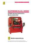
1
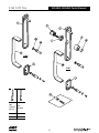
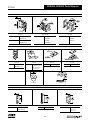
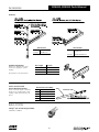
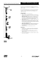
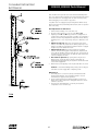
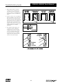
ED4000, ED5000 Series
Mechanical Pushpar Exit Devices
Parts and Service Manual
ED4000, ED5000 Parts Manual
Table of Contents
Introduction
Installation Notes . . . . . . . . . . . . . . . . . . . . . . . . . . . . . . . . . . . . . . . . . . . . . . . . . . . . . . . . . . . . . . . . . . . . . . . 3
How to Order Parts . . . . . . . . . . . . . . . . . . . . . . . . . . . . . . . . . . . . . . . . . . . . . . . . . . . . . . . . . . . . . . . . . . . . . 3
Finish Chart . . . . . . . . . . . . . . . . . . . . . . . . . . . . . . . . . . . . . . . . . . . . . . . . . . . . . . . . . . . . . . . . . . . . . . . . . . . 3
Exit Devices
ED5200(A) ED4200 Rim Exit Device . . . . . . . . . . . . . . . . . . . . . . . . . . . . . . . . . . . . . . . . . . . . . . . . . . . . . . . . 4
ED4200M(A) Rim Exit Device . . . . . . . . . . . . . . . . . . . . . . . . . . . . . . . . . . . . . . . . . . . . . . . . . . . . . . . . . . . . . 5
ED5200(A) ED4200S Rim Exit Device . . . . . . . . . . . . . . . . . . . . . . . . . . . . . . . . . . . . . . . . . . . . . . . . . . . . . . . 6
ED4200SM(A) Rim Exit Device . . . . . . . . . . . . . . . . . . . . . . . . . . . . . . . . . . . . . . . . . . . . . . . . . . . . . . . . . . . . 7
ED5400(A) ED4400 Surface Vertical Rod . . . . . . . . . . . . . . . . . . . . . . . . . . . . . . . . . . . . . . . . . . . . . . . . . . . 8-9
ED4400M(A) Surface Vertical Rod . . . . . . . . . . . . . . . . . . . . . . . . . . . . . . . . . . . . . . . . . . . . . . . . . . . . . . 10-11
ED5470(B) Surface Vertical Rod . . . . . . . . . . . . . . . . . . . . . . . . . . . . . . . . . . . . . . . . . . . . . . . . . . . . . . . . 12-13
ED5470(B) M55 Surface Vertical Rod (Less Bottom Rod) . . . . . . . . . . . . . . . . . . . . . . . . . . . . . . . . . . . . . 14-15
ED5800(A) ED4800 Concealed Vertical Rod Exit Device . . . . . . . . . . . . . . . . . . . . . . . . . . . . . . . . . . . . . 16-17
ED4800M(A) Concealed Vertical Rod Exit Device . . . . . . . . . . . . . . . . . . . . . . . . . . . . . . . . . . . . . . . . . . . 18-19
ED5860(B) Concealed Exit Device . . . . . . . . . . . . . . . . . . . . . . . . . . . . . . . . . . . . . . . . . . . . . . . . . . . . . . 20-21
ED5860B M55 Concealed Exit Device (Less Bottom Rod) . . . . . . . . . . . . . . . . . . . . . . . . . . . . . . . . . . . . . 22-23
ED5600(A) Mortise Exit Device . . . . . . . . . . . . . . . . . . . . . . . . . . . . . . . . . . . . . . . . . . . . . . . . . . . . . . . . 24-25
ED5000 DB Dummy Bar . . . . . . . . . . . . . . . . . . . . . . . . . . . . . . . . . . . . . . . . . . . . . . . . . . . . . . . . . . . . . . 26-27
ED4000/ED5000 bar Components . . . . . . . . . . . . . . . . . . . . . . . . . . . . . . . . . . . . . . . . . . . . . . . . . . . . . . 28-29
Trim
603F,
623F,
652F,
620F,
633F,
673F,
632F,
630F,
680F,
480F,
502F,
500F,
518F,
513F,
512F,
541F,
622F, 624F, 625F, 626F, 628F, 629F Trim . . . . . . . . . . . . . . . . . . . . . . . . . . . . . . . . . . . . . . . . . . . . . 30-31
627F Trim . . . . . . . . . . . . . . . . . . . . . . . . . . . . . . . . . . . . . . . . . . . . . . . . . . . . . . . . . . . . . . . . . . . . 32-33
654F, 656F, 658F Trim . . . . . . . . . . . . . . . . . . . . . . . . . . . . . . . . . . . . . . . . . . . . . . . . . . . . . . . . . . . 34-35
621F, 651F Trim . . . . . . . . . . . . . . . . . . . . . . . . . . . . . . . . . . . . . . . . . . . . . . . . . . . . . . . . . . . . . . . 36-37
635F Trim . . . . . . . . . . . . . . . . . . . . . . . . . . . . . . . . . . . . . . . . . . . . . . . . . . . . . . . . . . . . . . . . . . . . 38-39
675F Trim . . . . . . . . . . . . . . . . . . . . . . . . . . . . . . . . . . . . . . . . . . . . . . . . . . . . . . . . . . . . . . . . . . . . 40-41
634F, 662F Trim . . . . . . . . . . . . . . . . . . . . . . . . . . . . . . . . . . . . . . . . . . . . . . . . . . . . . . . . . . . . . . . 42-43
631F, 661F Trim . . . . . . . . . . . . . . . . . . . . . . . . . . . . . . . . . . . . . . . . . . . . . . . . . . . . . . . . . . . . . . . 44-45
681F, 684F Trim . . . . . . . . . . . . . . . . . . . . . . . . . . . . . . . . . . . . . . . . . . . . . . . . . . . . . . . . . . . . . . . . . . 46
481F, 482F, 483F Trim . . . . . . . . . . . . . . . . . . . . . . . . . . . . . . . . . . . . . . . . . . . . . . . . . . . . . . . . . . . . . . 47
504F, 505F, 506F, 508F, 509F Trim . . . . . . . . . . . . . . . . . . . . . . . . . . . . . . . . . . . . . . . . . . . . . . . . . 48-49
501F, 503F, 507F Trim . . . . . . . . . . . . . . . . . . . . . . . . . . . . . . . . . . . . . . . . . . . . . . . . . . . . . . . . . . . 50-51
519F Trim . . . . . . . . . . . . . . . . . . . . . . . . . . . . . . . . . . . . . . . . . . . . . . . . . . . . . . . . . . . . . . . . . . . . 52-53
517F Trim . . . . . . . . . . . . . . . . . . . . . . . . . . . . . . . . . . . . . . . . . . . . . . . . . . . . . . . . . . . . . . . . . . . . 54-55
514F Trim . . . . . . . . . . . . . . . . . . . . . . . . . . . . . . . . . . . . . . . . . . . . . . . . . . . . . . . . . . . . . . . . . . . . 56-57
546F, 548F, 549F Trim . . . . . . . . . . . . . . . . . . . . . . . . . . . . . . . . . . . . . . . . . . . . . . . . . . . . . . . . . . . 58-59
Levers and Knobs . . . . . . . . . . . . . . . . . . . . . . . . . . . . . . . . . . . . . . . . . . . . . . . . . . . . . . . . . . . . . . . . . . . . . 60
Cylinders . . . . . . . . . . . . . . . . . . . . . . . . . . . . . . . . . . . . . . . . . . . . . . . . . . . . . . . . . . . . . . . . . . . . . . . . . . . . . . 61
Strikes . . . . . . . . . . . . . . . . . . . . . . . . . . . . . . . . . . . . . . . . . . . . . . . . . . . . . . . . . . . . . . . . . . . . . . . . . . . . . . . . 62
Accessories . . . . . . . . . . . . . . . . . . . . . . . . . . . . . . . . . . . . . . . . . . . . . . . . . . . . . . . . . . . . . . . . . . . . . . . . 63-64
Mullions . . . . . . . . . . . . . . . . . . . . . . . . . . . . . . . . . . . . . . . . . . . . . . . . . . . . . . . . . . . . . . . . . . . . . . . . . . . . . . 65
Handing Instructions . . . . . . . . . . . . . . . . . . . . . . . . . . . . . . . . . . . . . . . . . . . . . . . . . . . . . . . . . . . . . . . 66-67
Surface Vertical Rod Devices . . . . . . . . . . . . . . . . . . . . . . . . . . . . . . . . . . . . . . . . . . . . . . . . . . . . . . . . . . . 68
Concealed Vertical Rod Devices . . . . . . . . . . . . . . . . . . . . . . . . . . . . . . . . . . . . . . . . . . . . . . . . . . . . . . . . . 69
Troubleshooting . . . . . . . . . . . . . . . . . . . . . . . . . . . . . . . . . . . . . . . . . . . . . . . . . . . . . . . . . . . . . . . . . . . . . . . 70
2
ED4000, ED5000 Parts Manual
Introduction
Installation Notes
1. Any retrofit or other field modification to a fire rated opening can potentially impact the fire rating of the opening, and Yale Locks & Hardware
makes no representations or warranties concerning what such impact may be in any specific situation. When retrofitting any portion of an
existing fire rated opening, or specifying and installing a new fire rated opening, please consult with a code specialist or local code
official (Authority Having Jurisdiction) to ensure compliance with all applicable codes and ratings.
2. Refer to the templates and installation instructions for complete door preparation and installation requirements.
3. Machine screws are provided for steel reinforced doors, threaded-to-the-head AB Type screws are provided for wood door applications. In
addition, sex nuts and bolts are provided for fire rated devices and are optional for non-rated devices. It is recommended that sex nuts and
bolts be used for all exit device applications. This will improve the performance and extend the life of the product.
How to Order Parts
1. In order to simplify the ordering procedure and maintain regulatory compliance, parts are only available as listed
2. To order parts, provide the appropriate quantity, part number, finish, hand (when required) and description as directed and
illustrated below.
For example, use the following configuration to order:
A) ten escutcheon assemblies (page 30) in satin chrome
B) one surface vertical rod latch cover (page 10) in bright brass
Quantity
Part Number
Finish
Hand
Description
A
10
677F01
626
—
Escutcheon Assemblies
B
1
650F64
605
—
Top Latch Cover
For assistance, contact your authorized Corbin Russwin distributor, sales agency or visit our website at www.corbinrusswin.com.
Finishes
ANSI/BHMA Code
Finish Description
605
Bright Brass, Clear Coated
606
Satin Brass, Clear Coated
611
Bright Bronze, Clear Coated
612
Satin Bronze, Clear Coated
613
Dark Oxidized Satin Bronze, Oil Rubbed
613E
Dark Oxidized Satin Bronze, Equivalent
618
Bright Nickel, Clear Coated
619
Satin Nickel Plated, Clear Coated
625
Bright Chrome Plated
626
Satin Chrome Plated
626C
Satin Chromium Plated with MicroShield®
629
Bright Stainless Steel
630
Satin Stainless Steel
630C
722
Satin Stainless Steel with MicroShield®
Black Oxidized Satin Bronze, Oil Rubbed
Finish available with MicroShield® antimicrobial coating, additional finishes by special
application. Consult factory for availability.
3
ED5200(A), ED4200
Rim Exit Device
ED4000, ED5000 Parts Manual
See Touchbar section for
Touchbar components
Pages 28 & 29
ED5200(A)
ED4200
Strike Pkg.
ED5200(A)
Strike Pkg.
ED4200
Item
Part No.
Description
Latch Assembly
1
650F358
ED5200
650F368
ED5200A
650F378
ED4200
ED4200
Hub Position
ED5200(A)
Hub
Position
Cover
2
650F00 x Fin
ED5200
Not Available
ED5200(A)
650F03 x Fin
ED4200
UL
31
650F308
ED5200(A) Strike Packet
32
650F318
ED4200 Strike Packet
33
655F718
(502) ED5200 Rim x VR Strike
4
ED4000, ED5000 Parts Manual
ED4200M(A) Rim Exit Device
See Touchbar section for
Touchbar components
Pages 28 & 29
Strike Pkg.
ED4200M(A)
Item
Part No.
Description
1
650F378
ED4200M
756F008
ED4200MA
Latch Assembly
2
650F03 x Fin
Cover ED4200M only
2
Not Available
Cover ED4200MA
31
650F308
ED4200M(A) Strike Packet
HUB
POSITION
5
ED4000, ED5000 Parts Manual
ED5200S(A), ED4200S
See Touchbar section for
Touchbar components
Pages 28 & 29
ED4200S
ED5200S(A)
Strike Pkg.
ED5200S(A)
Strike Pkg.
ED4200S
Item
1
Part No.
681F608
681F618
2
30
31
33
681F62 x Fin
Not Available
681F63 x Fin
730F778
650F318
655F718
Description
Latch Assembly
ED5200S, ED5200SA,
ED4200S
Cover
ED5200S
ED5200SA UL
ED4200S
ED5200S(A) Strike Packet
ED4200S Strike Packet
ED5200S Rim x VR Strike (S02)
6
ED4200S
Hub Position
ED5200S(A)
Hub
Position
ED4000, ED5000 Parts Manual
ED4200SM(A) Rim Exit Device
See Touchbar section for
Touchbar components
Pages 28 & 29
Strike Pkg.
ED4200SM(A)
Item
1
Part No.
Description
Latch Assembly
681F618
ED4200SM(A)
2
681F63 x Fin
ED4200SM
30
730F778
ED4200SM(A) Strike Packet
ED4200SM(A)
Hub
Position
Cover
7
Surface Vertical Rod
ED4400 / ED5400(A)
Item
Part No.
ED4000, ED5000 Parts Manual
Description
Item
Active Head
1
3
23
33
SVR Pack
ED5400, ED5400A RHR
Consists of the following:
650F398
ED5400, ED5400A LHR
Top Mtg. Plate
650F408
ED4400 RHR
Bottom Mtg. Plate
650F418
ED4400 LHR
Top Rod Connector
34
Rod Connecting Pin
650F01 x Fin
ED5400
Not Available
ED5400A
650F04 x Fin
ED4400
650F298 x Fin
Sex Nut Pack (2) required
Latch Mounting Screw Packet
Screw Packet, Cover
Top Strike Packet
704F63 x Fin
Drill Jig
Floor Bolt
UL
650F548
Strike -
Bottom Bolt Case
#8-32 x 5/16"
UFPHMS (5)
32
Description
650F578
650F388
Cover
2
Part No.
35
650F588
ED5400, ED4400
650F598
ED5400A
Latches (2)
36
650F60 x Fin
Top Rod
Top Latch
37
649F99 x Fin
Bottom Rod Assembly
650F558
ED5400, ED4400
39
650F62 x Fin
Rod Guide Packet
650F568
ED5400A
40
650F978
Pillow Block Packet ED4400
41
675F99 x Fin
Rod Guide Cover (2)
42
654F208
Wood Screw Paclet
not shown
650F64 x Fin
Cover, Top & Bottom
8
ED5400(A), ED4400
Surface Vertical Rod
ED4000, ED5000 Parts Manual
Strike Pkg.
Part of
Item 34
Strike Packet
See Touchbar section for
Touchbar components
Pages 28 & 29
ED4400
41
ED4400
Hub Position
ED5400(A)
Hub
Position
9
ED4000, ED5000 Parts Manual
ED4400M(A) Surface Vertical Rod
Item
Part No.
Description
Item
Part No.
Active Head
1
650F408
Bottom Bolt Case
ED4400M(A)
(Must Specify Hand)
35
Cover
2
3
650F04 x Fin
ED4400M
Not Available
ED4400M(A)
650F298
Sex Nut Pack (4) 2 required
Fire Rated Only or M54 option
704F63 x Fin
650F588
ED4400M
650F598
ED4400M(A)
36
650F60 x Fin
Top Rod
37
649F99 x Fin
Bottom Rod Assembly
UL
Rod Guide Packet
Consists of the following:
39
Screw Packet, Cover
23
650F62 x Fin
650F64 x Fin
Screw, #8-32 x 1/4" (2)
FPHMS (4)
Cover, Top & Bottom Latches (2)
40
675F99 x Fin
Rod Guide Cover (2)
41
654F208
Wood Screw Packet
not shown
Top Latch
33
650F558
ED4400M
650F568
ED4400MA
650F578
SVR Pack
Consists of the following:
Top Mtg. Plate
Bottom Mtg. Plate
Top Rod Connector
Rod Connecting Pin
34
Drill Jig
Floor Bolt
Strike
Latch Mounting Screw Pack
652F298
Sex Nut Pack (4) Fire Rated Only
650F548
Top Strike Packet
Guide, Rod (1)
Screw, #8 x 1/2 (2) RPHMS (4)
#8-32 x 5/16"
UFPHMS (5)
32
Description
10
ED4000, ED5000 Parts Manual
ED4400M(A) Surface Vertical Rod
See Touchbar section for
Touchbar components
Pages 28 & 29
Strike
Packet
(2) required
40
ED4400M(A)
HUB POSITION
11
ED4000, ED5000 Parts Manual
ED5470(B) Surface Vertical Rod
Item Part No.
1
Description
Item
650F388
ED5470(B) RHR
650F398
ED5470(B) LHR
3
35
650F01 x Fin
ED5470
Not Available
ED5470B
652F298
Sex Nut Pack (4) (Fire Rated Only)
or M54 Quick Code
UL
4
684F42 x Fin
Rod Extension Assy., 24"
5
655F17 x Fin
Rod Extension Assy., 12"
Screw Packet, Cover
23
704F63 x Fin
#8-32 x 5/16"
UFPHMS (5)
32
650F64 x Fin
Cover, Top & Bottom Latches (2)
Top Latch
33
650F558
ED5470
650F568
ED5470B
697F978
SVR Pack
Consists of the following:
Top Mtg. Plate
Bottom Mtg. Plate
Top Rod Connector
Rod Connecting Pin
34
Drill Jig
Floor Bolt
Strike
Latch Mounting Screw Pack
Latch Mounting Screw (4)
(Wood Door Panic)
681F708
Description
Bottom Bolt Case
Cover
2
Part No.
Active Head
Top Strike Packet
12
650F588
ED5470
650F598
ED5470B
36
650F60 x Fin
Top Rod
37
649F99 x Fin
Bottom Rod Assembly
39
650F62 x Fin
Rod Guide Packet
40
675F99 x Fin
Rod Guide Cover (2-covers)
41
654F208
Wood Screws not shown
ED4000, ED5000 Parts Manual
ED5470(B) Surface Vertical Rod
Strike
Packet
See Touchbar section for
Touchbar components
Pages 28 & 29
ED5470(B)
HUB
POSITION
40
13
ED4000, ED5000 Parts Manual
ED5470(B) x M55 (Less Bottom Rod)
Item
Part No.
1
2
Description
Part No.
Description
654F158
SVR Pack
650F388
ED5470(B) RHR
Consists of the following:
650F398
ED5470(B) LHL
Top Mtg. Plate
Cover
Top Rod Connector
650F01 x Fin
ED5470
Not Available
ED5470B
3
652F298
Sex Nut Pack (4), Fire Only
& M54
4
684F42 x Fin
Rod Extension Assy., 24"
5
655F17 x Fin
Rod Extension Assy., 12"
Screw Packet, Cover
23
Item
Active Head
704F63 x Fin
Rod Connecting Pin
34
Drill Jig
Latch Mounting Screw Pack
Latch MountingScrew(2)
(wood doors, panic)
36
#8-32 x 5/16"
681F708
Top Strike Packet
650F60 x Fin
Top Rod
650F62 x Fin
Rod Guide Packet
UFPHMS (5)
32
650F64 x Fin
Cover, Top & Latch
33
650F558
Top Latch, ED5470
650F568
Top Latch, ED5470B
Consists of the following:
Guide, Rod (1)
39
Cover, Rod Guide (1)
Screw, #8 x 1/2 (2) RPHMS (4)
Screw, #8-32 x 1/4" (2) FPHMS (4)
55
744F688 x Fin
Popper Packet [Fire Rated (B) Only]
40
675F99 x Fin
Rod Guide Cover
41
654F208
Wood Screws
14
ED4000, ED5000 Parts Manual
ED5470(B) x M55 (Less Bottom Rod)
Strike
Packet
See Touchbar section for
Touchbar components
Pages 28 & 29
ED5470(B)
HUB
POSITION
15
Concealed Vertical Rod
ED4800 / ED5800(A)
Item
Part No.
ED4000, ED5000 Parts Manual
Description
Active Head
1
650F438
ED5800(A) RHR
650F448
ED5800(A) LHR
650F458
ED4800 RHR
650F468
ED4800 LHR
Cover, Latch Assembly
2
650F02 x Fin
ED5800
not available
ED5800A
650F05 x Fin
ED4800
Bottom Bolt Case
35
36
650F748
ED5800
650F758
ED5800A
650F768
ED4800
650F808
Top Rod
707F268
CVR Pack for ED5800(A) & ED4800
Consists of the following:
Floor Bolt
Strike
650F548
Top Strike Packet
Pin, Rod Yoke (2)
46
Set Screw, Yoke Pin
Cotter Pin (5)
Ring, Retaining (2)
2" Temp Screw (2)
Screw Pack
Top Latch & Bracket Assembly
47
650F718
ED5800
650F728
ED5800A
650F738
ED4800
49
650F798
Bottom Rod & Coupler Assembly
51
650F818
Top Rod Tube
52
707F257
Arm & Bracket Assy (2)
53
654F208
Wood Screw Packet not shown
16
ED5800(A), ED4800
Concealed Vertical Rod
ED4000, ED5000 Parts Manual
ED5800(A) LATCH
BRACKETS FOR
METAL DOORS
ED5800(A) &
ED4800
See Touchbar section for
Touchbar components
Pages 28 & 29
Strike
Packet
ED4800
hub position
ED5800(B)
hub
position
17
Concealed Vertical Rod
ED4800M(A)
Item
1
2
Part No.
ED4000, ED5000 Parts Manual
Description
Active Head
650F458
ED4800M(A) RHR
650F468
ED4800M(A) LHR
Cover, Latch Assembly
650F05 x Fin
ED4800M
not available
ED4800MA
UL
Bottom Bolt Case
35
36
650F748
ED4800M
650F758
ED4800MA
650F808
Top Rod
707F268
CVR Pack
Consists of the following:
Floor Bolt
Strike
650F548
Top Strike Packet
Pin, Rod Yoke (2)
46
Set Screw, Yoke Pin
Cotter Pin (5)
Ring, Retaining (2)
Screw Pack
2" Temp Screw (2)
Top Latch & Bracket Assembly
47
650F748
ED4800M
650F758
ED4800MA
49
650F798
Bottom Rod & Coupler Assembly
51
650F818
Top Rod Tube
52
707F257
Arm & Bracket Assy (2)
53
654F208
ED4800M(A) Wood Screws (Optional)
18
Concealed Vertical Rod
ED4800M(A)
ED4000, ED5000 Parts Manual
TOP STRIKE
PACKET PART OF
CVR PACK ITEM
46
ED4200M(A)
LATCH BRACKETS
FOR METAL
DOORS
Strike
Packet
See Touchbar section for
Touchbar components
Pages 28 & 29
ED4800M(A)
HUB
POSITION
19
ED4000, ED5000 Parts Manual
ED5860(B) Concealed Vertical Rod
Item
1
2
Part No.
Description
Latch Case Assembly
650F438
ED5860(B) RHR
650F448
ED5860(B) LHR
Cover, Latch Assembly
650F02 x Fin
ED5860
Not Available
ED5860B
650F748
Bottom Bolt Case ED5860
650F758
Bottom Bolt Case ED5860B
36
650F808
Top Rod
37
655F17 x Fin
12" Rod Assembly
684F42 x Fin
24" Rod Assembly
698F048
CVR Pack
35
UL
Rod Extension Assembly
Consists of the following:
Floor Bolt
Strike
681F778
Top Strike Packet
Pin, Rod Yoke (2)
46
Set Screw, Yoke Pin
Yoke Pin Spacer (2)
Cotter Pin (5)
Ring, Retaining (2)
Screw Pack
2" Temp Screw (2)
49
650F798
Bottom Rod & Coupler Assembly
51
650F818
Top Rod Tube
52
707F257
Arm & Bracket Assy. (2)
53
654F208
ED5860 Wood Screws (Optional)
20
ED4000, ED5000 Parts Manual
ED5860(B) Concealed Vertical Rod
Strike Packet
See Touchbar section for
Touchbar components
Pages 28 & 29
21
Concealed Vertical Rod ED5860(B)
x M55 (Less Bottom Rod)
Item
1
Part No.
ED4000, ED5000 Parts Manual
Description
Latch Case Assembly
650F438
ED5860(B) RHR
650F448
ED5860(B) LHR
Cover, Latch Assembly
2
650F02 x Fin
ED5860
Not Available
ED5860B
36
650F808
Top Rod
37
655F17 x Fin
12" Rod Assembly
684F42 x Fin
24" Rod Assembly
698F058
CVR Pack
UL
Rod Extension Assembly
Consists of the following:
681F778
Top Strike Packet
Pin, Rod Yoke (1)
Set Screw, Yoke Pin
46
Yoke Pin Spacer (1)
Cotter Pin (3)
Ring, Retaining (1)
Screw, 10-24 x 1/2 FHM-PH (6)
8x32x2 Temp Screw (1)
47
681F768
Top Latch & Bracket Assembly,
ED5860(B)
51
650F818
Top Rod Tube
52
707F257
Arm & Bracket Assembly (1)
55
744F688
Popper Pack (Fire Rated Only)
56
654F208
Wood Screws (Optional)
22
Concealed Vertical Rod ED5860(B)
x M55 (Less Bottom Rod)
ED4000, ED5000 Parts Manual
Strike
Packet
See Touchbar section for
Touchbar components
Pages 28 & 29
23
ED5600(A) Mortise Exit Device &
ED5602(A)
Item
1
2
Part No.
Description
706F098
Active Head ED5602(A) RHR
706F108
Active Head ED5602(A) LHR
650F428
ED5600(A)
706F15
Cover ED5602 RHR
706F16
Cover ED5602 LHR
650F02 x Fin
ED5600
Not Available
ED5600A
ED4000, ED5000 Parts Manual
Mortise Lock Body Specify Hand
42
678F008 x Hand
ED5600T(A)
650F678 x Hand
ED5657K(A), ED5657T(A), ED5657K(A)
655F488 x Hand
ED5600K(A)
655F698 x Hand
ED5600L(A)
43
650F06 x Fin
Armored Front
45
650L657020622
Strike Packet
46
706F485
Cylinder Housing ED5602(A) Not Shown
47
706F462
Mortise Cylinder Adapter ED5602(A)
Not Shown
429F41 x FIN
Mounting Pack
48
Screw, 8-32 x 1/4 UFPHMS (2)
Screw, #12/12-24 Comb.UFPHMS (2) & Cyl
Open Back Strike - Optional
49
50
653L163016 622
Straight Lip 1-3/4 Door
653L183016 622
Curved Lip 1-3/4 Door
654F208
Wood Screws
24
ED5600(A) Mortise Exit Device &
ED5602(A)
ED4000, ED5000 Parts Manual
See Touchbar section for
Touchbar components
Pages 28 & 29
44
25
ED4000, ED5000 Parts Manual
ED5000DB Dummy Bar
Item
Part No.
Description
4
650F21 x Fin
Bottom Rail, 48"
5
650F93 x Fin
Cover
7
650F998
Carrier Bar
11
704F642 x Fin
End Cap (2)
704F648
Device Mounting Pack (2)
Consists of the following:
21
End Clamp
Screw, 1/4-20 X 1 PPHMS
22
704F63 x Fin
Packet, Cover Screw
23
654F208
Wood Screw Packet not shown
26
ED4000, ED5000 Parts Manual
ED5000DB Rigid Bar
22
27
ED4000, ED5000 Parts Manual
Pushbar Parts List
Item Part No.
1
2
See specific
devices pgs. 4-26
See specific
devices pgs. 4-26
Description
5
6
Active Heads Covers
Dogging Assembly
650F528
15
HexKey (Standard)
650F968
Cylinder Dogging
656F408
Dogging Key (5/32" Hex)
16
650F279
Dogging Hole Plug
17
697F862
Cylinder Nut
650F959
Cylinder Spacer
691F16 Fin
24" ED4000
18
656F75 Fin
24" ED5000
19
650F20 FIn
36" ED4000
None Required
1 1/8" Cylinder
650F19 Fin
36" ED5000
270F15 x Fin
1-1/4" Cylinder
650F21 Fin
48" ED4000, ED5000, ED5000DB
610F02 x Fin
1-3/4" Cylinder
Bar & Carrier Assembly
654F07 x Fin
1-1/2" Cylinder
Collar, Dogging Cylinder
20
Cylinder Dogging Cylinder
691F148
24" ED4000
656F768
24" ED5000
650F238
36" ED4000
650F228
36" ED5000
704F648
650F248
48" ED4000, ED5000
704F658
SecureBolt Devices
650F998
48” ED5000DB
22
650F288 622
Screw, Touchbar Caps (4)
Cover, Bar
23
704F63 Fin
Screw Pack, Ecn Cap & Active Head Cover
24
711F608
Screw Dogging Assembly (2)
25
650F508
Screw, Trim Slide
26
650F518
Screw, Active Head to Carrier
28
650F298 Fin
Sex Nut Packet (4-SNB’s) ED5200(A) S
681F698 Fin
SecureBolt (6SNB’s) ED5200SA
56
704F888
High Impact End Clamp (M109) Optional
656F72 Fin
24" ED4000, ED5000
650F07 Fin
36" ED4000, ED5000
650F08 Fin
48" ED4000, ED5000
676F29 Fin
24" ED4000, ED5000 Embossed (M22)
656F69 Fin
36" ED4000, ED5000 Embossed (M22)
656F70 Fin
48" ED4000, ED5000 Embossed (M22)
710F797
24" ED4000, ED5000 Photoluminescent (M49)
710F737
36" ED4000, ED5000 Photoluminescent (M49)
710F747
48" ED4000, ED5000 Photoluminescent (M49)
Cover, End
691F15 Fin
24" ED4000 Hexkey Dogging
691F17 Fin
24" ED4000 Cylinder Dogging
656F73 Fin
24" ED5000 Hexkey Dogging
656F74 Fin
24" ED5000 Cylinder Dogging
650F13 Fin
36" ED4000 Hexkey Dogging
650F14 Fin
36" ED4000 Cylinder Dogging
650F11 Fin
36" ED5000 Hexkey Dogging
650F12 Fin
36" ED5000 Cylinder Dogging
650F15 Fin
48" ED4000, ED5000 Hexkey Dogging
650F16 Fin
48" ED4000, ED5000 Cylinder Dogging
650F93 Fin
48" ED5000DB
8
711F685
622
Touch Pad Cap, Front
9
710F495
622
Touch Pad Cap, Rear
7
Description
14
Active Heads
Bottom Rail
3
Item Part No.
10
650F189
Bar Cap, Black Nylon
11
704F62 Fin
End Cap
12
As Ordered
21
All Except Mortise
N/A
Mortise Trim Slide (attached to Active Head)
13
All Except Mortise
694F848
Mortise Trim Slide Retainer
All except SecureBolt
#10-32 x 1/2" PHT-PH (1)
#8-32 x 1/2" FHT-PH (1)
#8-32 x 1/4" PHT-C-PH (2)
Trim Slide Retainer
650F489
End Clamp Packet
#8-32 x 5/8" PHT-PH
Trim Slide
650F489
Mortise Cylinder x A02 Cam
28
ED4000, ED5000 Parts Manual
Touchbar
23
ED5000
HUB
POSITION
ED4000,
ED4000M
(F) HUB
POSITION
56
29
ED4000, ED5000 Parts Manual
*910, *950, *955, *959 Trim
Item
Part No.
Description
Item
Part No.
Escutcheon
1
(All other knobs/levers)
Tailpiece Assembly
677F068
1 3/4" Door w/o Shim Kit
677F00 x Fin
*910, *950
655F708
2 -21/4" Door or Std. Door w/Shim Kit
677F01 x Fin
*955, *959
701F648
2 1/2"-3 1/2" Door
Escutcheon
701F658
3 1/2"-4 1/2"
(Museo Levers)
10
11
*910, *955
651F648
Lever
806F01 x Fin
*955, *959
677F258
Knob
Parabolic Escutcheon
12
677F085
Hub, Spring Retaining
(All other knobs/levers)
14
677F098
Cotter Pin
708F26 x Fin
*910, *950
15
677F078
Nut, Spindle
708F23 x Fin
*955, *959
16
(Museo Levers)
806F03 x Fin
*910, *950
806F04 x Fin
*955, *959
677F04 X Fin
Lustra
677F05 X Fin
Newport
677F13 X Fin
Essex
677F14 X Fin
Regis
677F15 X Fin
Citation
677F16 X Fin
Armstrong
677F26 X Fin
Dirke RHR
677F27 X Fin
677F28 X Fin
Bushing, Nylon
677F029
Lever (All except Museo)
651F389
Knob
806F069
Lever - Museo
17
Lever and Spindle (non-Muséo)
Screw Pkt., Mtg.
652F128 x Fin
1 3/4"-2" Doors
652F138 x Fin
2"-2 1/4" Doors
Torsion Springs not shown
18
651F618
Lever, LHR (Red)
651F628
Lever RHR (Blue)
651F758
Knob
19
651F408
Compression Spring (Under tailpiece)
not shown
Dirke LHR
20
651 F398
Hex Nut Bushing for Spring not shown
Princeton
21
651F708
Bushing, Spacer
698F31 X Fin
Tuscany
22
651F438
Threaded Post (4)
698F32 X Fin
Merlot
23
386F018
Retaining Ring (under threaded post)
698F64 X Fin
Frascati RHR
24
677F128
Set Screw (1) 1/4"-20 x 1" not shown
698F66 X Fin
Frascati LHR
698F68 X Fin
Zinfandel RHR
26
677F118
Set Screw (10 1/4"-20 x 5/8"
(hex nut bushing) not shown
698F70 X Fin
Zinfandel LHR
Knob & Spindle SA
656F45 X Fin
Global
3
See Chart Page ??
Rim Cylinder
5
651F675
Cylinder Housing (*955, *959)
6
655F028
Screw Cylinder Mounting (2)
Included with
Function Selector Screw
Cylinder Housing
(*955, *959)
8
651F638
Driven Gear Assembly
9
651F508
Screw, Tailpiece Plate (2)
7
Gear, Drive
806F00 x Fin
Parabolic Escutcheon
2
Description
30
ED4000, ED5000 Parts Manual
Museo Levers
Part No.
Description
Part No.
Description
800R02 x Fin
101
800R22 x Fin
131 RHR
800R807 x Fin
102
800R827 x Fin
131 LHR
800R12 x Fin
103
800R32 x Fin
132 RHR
800R17 x Fin
104
800R37 x Fin
132 LHR
800R22 x Fin
105
800R27 x Fin
106
800R32 x Fin
107
800R37 x Fin
108
800R42 x Fin
109
800R47 x Fin
110
800R52 x Fin
111 RHR
800R57 x Fin
111 LHR
800R62 x Fin
112 RHR
800R67 x Fin
112 LHR
800R72 x Fin
113 RHR
800R77 x Fin
113 LHR
800R82 x Fin
114 RHR
800R87 x Fin
114 LHR
800R92 x Fin
115 RHR
800R97 x Fin
115 LHR
801R02 x Fin
116 RHR
801R07 x Fin
116 LHR
801R12 x Fin
117
801R17 x Fin
118 RHR
801R22 x Fin
118 LHR
801R27 x Fin
119 RHR
801R32 x Fin
119 LHR
801R37 x Fin
120
801R42 x Fin
121 RHR
801R47 x Fin
121 LHR
801R52 x Fin
122 RHR
801R57 x Fin
122 LHR
801R62 x Fin
123
801R72 x Fin
124
801R77 x Fin
125
801R82 x Fin
126 RHR
801R87 x Fin
126 LHR
801R92 x Fin
127 RHR
801R97 x Fin
127 LHR
802R02 x Fin
128
802R07 x Fin
129
802R12 x Fin
130 RHR
802R17 x Fin
130 LHR
31
ED4000, ED5000 Parts Manual
Piet Levers
Part No.
Description
802R46
629 21G 29 29 29
803R56
629 21G 29 30 29
804R91
630 21G 30 30 30
804R96
630 21G 30 29 30
802R82
630 21L 30 BK 30
802R87
630 21L 30 BN 30
802R92
629 21L 29 BK 29
807R97
629 21L 29 BN 29
803R02
629 21M 29 30 29
803R07
630 21S 30 BK 30
803R12
629 21S 29 BK 30
803R17
630 21W 30 BH 30
803R22
629 21W 29 BH 29
803R27
629 23M 29 00 30
803R42
629 23M 29 00 29
803R47
630 23M 30 00 30
803R52
630 23M 30 00 29
803R32
629 25M 29 00 29
803R37
630 25M 30 00 30
32
ED4000, ED5000 Parts Manual
*910, *950, *955, *959 Trim
23
22
33
ED4000, ED5000 Parts Manual
*957, G957 Trim
Item
Part No.
1
Description
Escutcheon Assy. 623F, 627F
6951F18 x Fin
Standard
806F02 x Fin
Museo
708F25 x Fin
Standard Parabolic
806F05 x Fin
Museo Parabolic
2
See Chart page 30a
Lever / Knob See pg 30a
3
See Chart Page 61
Cylinder, Rim*
5
651F425
Housing, Cylinder
6
655F028
Screw, Cylinder Mounting (2)
11
651F648
Gear, Drive
12
677F085
Spring Retainer Hub
14
677F098
Cotter Pin
15
677F078
Nut, Spindle
16
677F029
Bushing Lever
Screw Packet, Mtg.
17
18
652F128 x Fin
1-3/4" - 2" Doors
652F138 x Fin
2-1/4" Doors
Spring, Grip Return
651F758
Knob Not Shown
651F628
Lever Return Spring RHR
651`F618
Lever Return Spring LHR
*See page 61 for cylinder collar applications.
34
ED4000, ED5000 Parts Manual
*957, G957 Trim
*957
35
*9M10, *9M50, *9M55,
*9M57 Trim
Item
1
2
Part No.
ED4000, ED5000 Parts Manual
Description
Item
Part No.
Description
Escutcheon Assembly
2 cont.
801Y17 x Fin
118 RHR
118 LHR
677F01 x Fin
Cylinder x Lever or Knob
801Y22 x Fin
677F00 x Fin
Blank x Lever or Knob
801Y27 x Fin
119 RHR
Escutcheon Assembly Museo
801Y32 x Fin
119 LHR
806F01 x Fin
Lever & Cylinder Hole
801Y37 x Fin
120
806F00 x Fin
Lever Hole Only
801Y42 x Fin
121 RHR
653F50 x Fin
Essex
801Y47 x Fin
121 LHR
653F53 x Fin
Lustra
801Y52 x Fin
122 RHR
653F56 x Fin
Regis
801Y57 x Fin
122 LHR
653F59 x Fin
Citation
801Y62 x Fin
123
653F62 x Fin
Dirke RHR
801Y72 x Fin
124
653F65 x Fin
Dirke LHR
801Y77 x Fin
125
653F68 x Fin
Newport
801Y82 x Fin
126 RHR
653F71 x Fin
Armstrong
801Y87 x Fin
126 LHR
653F74 x Fin
Princeton
801Y92 x Fin
127 RHR
698F32 x Fin
Tuscany
801Y97 x Fin
127 LHR
698F34 x Fin
Merlot
802R02 x Fin
128
698F65 x Fin
Frascati RHR
802R07 x Fin
129
698F67 x Fin
Frascati LHR
802R12 x Fin
130 RHR
698F69 x Fin
Zinfandel RHR
802R17 x Fin
130 LHR
698F71 x Fin
Zinfandel LHR
802R22 x Fin
131 RHR
800Y02 x Fin
101
802R27 x Fin
131 LHR
800Y07 x Fin
102
802R32 x Fin
132 RHR
800Y12 x Fin
103
802R37 x Fin
132 LHR
800Y17 x Fin
104
802Y467
629 21G 29 29 29
800Y22 x Fin
105
803Y567
629 21G 29 30 29
800Y27 x Fin
106
804Y917
630 21G 30 30 30
800Y32 x Fin
107
804Y967
630 21G 30 29 30
800Y37 x Fin
108
802Y827
630 21L 30 BK 30
800Y42 x Fin
109
802Y877
630 21L 30 BN 30
800Y47 x Fin
110
802Y927
629 21L 29 BK 29
800Y52 x Fin
111 RHR
802Y977
629 21L 29 BN 29
800Y57 x Fin
111 LHR
803Y027
629 21M 29 30 29
800Y62 x Fin
112 RHR
803Y077
630 21S 30 BK 30
800Y67 x Fin
112 LHR
803Y127
629 21S 29 BK 29
800Y72 x Fin
113 RHR
803Y177
630 21W 30 BH 30
800Y77 x Fin
113 LHR
803Y227
629 21W 29 BH 29
800Y82 x Fin
114 RHR
803Y277
629 23M 29 00 30
800Y87 x Fin
114 Lhr
803Y427
629 23M 29 00 29
800Y92 x Fin
115 RHR
803Y477
630 23M 30 00 30
800Y97 x Fin
115 LHR
803Y527
630 2M 30 00 29
801Y02 x Fin
116 RHR
803Y327
629 25M 29 00 29
801Y07 x Fin
116 LHR
803Y377
630 25M 30 00 30
801Y12 x Fin
117
804Y837
629 27M 29 00 29
804Y877
630 27M 30 00 30
36
*9M10, *9M50, *9M55,
*9M57 Trim
Item Part No.
ED4000, ED5000 Parts Manual
Description
3
See Chart page 60
Cylinder, Mortise*
14
677F098
Cotter Pin
15
698F088
Nut, Spindle
Thimble Insert, Nylon Not Shown
16
677F029
Levers
651F389
Knob
806F069
Museo
17
Screw Packet, Mtg.
652F128 x Fin
1-3/4" - 2" Doors
652F138 x Fin
2-1/4" Doors
Consists of the following:
Screw, 1/4-20 x 1 OPHMS (2)
Washer, #14 Finish (2)
24
651F648
25
Gear
Spindle
698F108
1-3/4" - 2-1/4"
3
2
24
25
15
Sold as a lever &
Spindle assembly (2)
656F, 658F
14
37
ED4000, ED5000 Parts Manual
F950, F957, F9M57, 651F Trim
Item
Part No.
Description
Escutcheon Standard
1
676F04 x Fin
F950
676F03 x Fin
F957
694F76 x Fin
F9M57
Escutcheon Parabolic
708F20 x Fin
F950
708F24 x Fin
F957
708F22 x Fin
F9M57
3
See Chart Page 61
Cylinder, Rim or Mortise*
5
651F425
Housing, Cylinder F957
6
655F028
Screw, Cylinder F957 Mounting (2)
Screw Packet, Mtg.
17
651F128 x Fin
1-3/4"- 2" DOor
651F138 x Fin
2-1/4" Door
Consists of the following:
Screw, 1/4-20 x 1 OPHMS (2)
Washer, #14 Finish (2)
22
651F438
Threaded Post (4)
23
386F018
Retaining Ring (4)
* See page 61 for cylinder collar applications
38
F950, F957, F9M57, 621F,
651F Trim
ED4000, ED5000 Parts Manual
F957
F9M57
(NL)
(EO)
(NL) Access
Access by
Blank Plate by Key
Key
01
03
07
F950
F957
F9M57
F950
39
ED4000, ED5000 Parts Manual
TH910, TH955 Trim
need artwork
40
ED4000, ED5000 Parts Manual
TH910, TH955 Trim
need artwork
41
ED4000, ED5000 Parts Manual
TH9M10, TH9M55 Trim
need artwork
42
ED4000, ED5000 Parts Manual
TH9M10, TH9M55 Trim
need artwork
43
ED4000, ED5000 Parts Manual
TH950, TH957, TH9M57
need artwork
44
ED4000, ED5000 Parts Manual
TH950, TH957, TH9M57
need artwork
45
ED4000, ED5000 Parts Manual
P950, P957, P9M57 Trim
681F
7
Item
Part No.
Description
652F12 x Fin
652F13 x Fin
Screw Packet, Mtg.
1-3/4" - 2" Door
2-1/4" Door
1
Consists of the following:
Screw 1/4-20 x 1 OPHMS(2)
Washer #14 Finish (2)
Dummy
Pull
Nightlatch
Mortise
Nightlatch
3
See Chart Page 61
Cylinder, Rim or Mortise
5
651F425
Housing, Cylinder (681F)
6
655F028
Screw, Cylinder Mtg. (2)
7
02
P950
03
P957
Escutcheon & Pull Assembly
03
P9M57
46
711F22 x Fin
P950
711F23 x Fin
P957
7155F53 x Fin
P9M57
ED4000, ED5000 Parts Manual
P1050, P1057 Trim
481F
Item
Part No.
Description
Screw Packet, Mtg.
Consists of the following:
1
Screw 1/4-20 x 1 OPHMS(2)
Washer #14 Finish (2)
3
Dummy
Pull
Nightlatch
03
P1050
P1057
Cylinder, Rim
5
Housing, Cylinder (651F425)
6
Screw, Cylinder Mtg. (2) (655F028)
7
02
See Chart Page 61
676F12 x Fin
Escutcheon & Pull Assembly (P1050)
676F13 x Fin
Escutcheon & Pull Assembly (P1057)
47
ED4000, ED5000 Parts Manual
*810, *850, *855, *859 Trim
Item
Part No.
Description
Escutcheon Assembly
651F02 x Fin (Std. lever)
1
651F02 x Fin (Museo Lever)
651F03 x Fin (Std. lever)
651F03 x Fin (Museo lever)
*855, *859
*810, *850
2
See Chart page 60
Lever/Knob
3
See Chart Page 61
Rim Cylinder
4
See Chart Page 61
Cylinder Collar
Housing & Cam Assembly
5
651F965
*855, *859, Housing, Cyl.
655F665
*810, *850
6
655F028
Screw, Cylinder Mounting (2)
7
656F658
Screw, NL Function
Thimble Insert, Nylon
16
Not Shown
Spring Under Tailpiece
19
651F408
25
651F858
Plate, Cover
26
651F948
Spring, Extension (Levers Only)
27
651F928
Nut, Spring Post (Levers Only)
Not Shown
Rack & Tailpiece Assy. Levers/
Knobs
28
651F828
*810, *855, *859
652F218
*850
29
651F538
Lever, Clutch
30
651F838
Pin, Clutch Lever
31
651F898
Retainer, Clutch Lever Pin (2)
32
651F888
Nut, Cover Plate (2) Not Shown
33
652F228
Cain Not Shown
34
652F239
Bushing, Nylon Not Shown
35
651F848
Washer, Grip Not Shown
36
651F878
Screw, 8-32 x 7/16, Spindle
Not Shown
Spring, Rack (2)
37
38
651F938
Lever
651F868
Knob, Thumbturn
651F17 x Fin
806F22 x Fin
Thumble - Std. Levers
Not Shown
Thumble - Museo Levers
Not Shown
48
ED4000, ED5000 Parts Manual
*810, *850, *855, *859 Trim
Item
2
Description
Item
Part No.
Description
656F46 x Fin
Global Knob & Spindle Assembly
2
801N62 x Fin
123
652F84 x Fin
Essex
801N72 x Fin
124
652F87 x Fin
Lustram
801N77 x Fin
125
652F90 x Fin
Regis
801N82 x Fin
126 - RH
652F93 x Fin
Citation
801N87 x Fin
126 - LH
652F96 x Fin
Dirke RHR
801N92 x Fin
127 - RH
652F99 x Fin
Dirke LHR
801N97 x Fin
127 - LH
653F02 x Fin
Newport
802N02 x Fin
128
653F05 x Fin
Armstrong
802N05 x Fin
129
653F08 x Fin
Princeton
802N12 x Fin
130 - RH
800N02 x Fin
101
802N17 x Fin
130 - LH
800N07 x Fin
102
802N22 x Fin
131 - RH
800N12 x Fin
103
802N27 x Fin
131 - LH
800N17 x Fin
104
802N32 x Fin
132 - RH
800N22 x Fin
105
802N37 x Fin
132 - LH
800N27 x Fin
106
802N467 629
21G 29 29 29
800N32 x Fin
107
803N567 629
21G 29 30 29
800N37 x Fin
108
804N917 630
21G 30 30 30
800N42 x Fin
109
804N967 630
21G 30 29 30
800N47 x Fin
110
802N827 630
21L 30 BK 30
800N52 x Fin
111 - RH
802N877 630
21L 30 BN 30
800N57 x Fin
111 - LH
802N927 629
21L 29 BK 29
800N62 x Fin
112 - RH
802N977 629
21L 29 BM 29
800N67 x Fin
112 - LH
803N027 629
21M 29 29 29
800N72 x Fin
113 - RH
803N077630
21S 30 BK 30
800N77 x Fin
113 - LH
803N127 629
21S 29 BK 29
800N82 x Fin
114 - RH
803N177 630
21W 30 BH 30
800N87 x Fin
114 - LH
803N227 629
21W 29 BH 29
800N92 x Fin
115 - RH
803N277 629
23M 29 00 30
800N97 x Fin
115 - LH
803N427 629
23M 29 00 29
801N02 x Fin
116 - RH
803N477 630
23M 30 00 30
801N07 x Fin
116 - LH
803N527 630
23M 30 00 29
801N12 x Fin
117
803N327 629
25M 29 00 29
801N17 x Fin
118 - RH
803N377 630
25M 30 00 30
801N22 x Fin
118 - LH
804N837 629
27M 29 00 29
801N27 x Fin
119 - RH
804N877 629
27M 30 00 30
801N32 x Fin
119 - LH
801N37 x Fin
120
801N42 x Fin
121 - RH
801N47 x Fin
121 - LH
801N52 x Fin
122 - RH
801N57 x Fin
122 - LH
Part No.
49
ED4000, ED5000 Parts Manual
*810, *850, *855, *859 Trim
Cylinder
Controls
Knob
Passage
Trim Knob
Rigid
Dummy
Knob
Cylinder
Controls
Lever
Passage
Trim Lever
Rigid
Dummy
Lever
09
--
02
08
--
02
G855,
G859
G810
G850
*855, *859
*810
*850
50
500F, 501F, 503F, 507F, F450,
F457, 0855, 0859, 0810 Trim
Item
Part No.
ED4000, ED5000 Parts Manual
Description
Escutcheon Assembly
1
651F00 x Fin
F450
651F01 x Fin
F457
651F02 x Fin
0855, 0859
652F03 x Fin
0810
2
656F53 x Fin
Thumbturn / Spindle Assembly
3
See Chart Page 61
Cylinder, Rim 4
See Chart Page 61
Collar, Cylinder
Housing & Cam Assembly
5
651F965
0855, 0859
651F425
F457, Housing, Cylinder
6
655F028
Screw, Cylinder Mounting (2)
7
656F658
Screw, NL Function
16
651F389
Thimble Insert, Nylon Not Shown
19
651F408
25
651F858
Plate, Cover
28
651F878
Rack & Tailpiece Assembly
29
651F538
Lever, Clutch 0855, 0859
30
651F838
Pin, Clutch Lever 0855, 0859
31
651F898
Retainer, Clutch Lever Pin (2) 0855, 0859
32
651F888
Nut, Cover Plate (2)
33
652F228
Cam Not Shown
34
652F239
Bearing, Nylon Not Shown
35
651F848
Washer, Grip Not Shown
36
81-0611-0410-036
Screw, 8-32 x 7/16 Spindle Not Shown 651F878
37
60-7200-1133-000
Spring, Rack (2) 651F868
Spring Under Tailpiece for 0810, 0855, 0859
Not Shown
51
F450, F457, 0855, 0859,
0810 Trim
ED4000, ED5000 Parts Manual
F457
F450
0810, 0855,
0859
(EO)
Blank
Plate
(NL)
Access by
Key
Cylinder Controls
Thumbturn
Passage
Active
Turn
--
03
11/12
--
F450
F457
0855, 0859
0810
52
ED4000, ED5000 Parts Manual
T1455, T1410, T1459
Item
Part No.
Description
Escutcheon Assembly
1
651F09 x Fin
T1440 Top
651F08 x Fin
T1455 Top
651F10 x Fin
Bottom
2
566F50 x Fin
Thumbpiece
3
See Chart Page 61
Cylinder, Rim 4
See Chart Page 61
Collar, Cylinder
5
655F675
T1410 Housing, Cylinder, Gear
6
655F028
T1455, T1459 Screw, Cylinder Mounting (2)
7
656F658
Screw, NL Function
17
652F10 x Fin
1 3/4" - 2" Door Screw Packet, Mtg.
652F11 x Fin
2-1/4" Door Screw Packet, Mtg.
Consists of the following:
Screw, 1/4-20 x 1 OPHMS (1)
Washer, #14 Finish (1)
Spring Under Tailpiece T1455, T1459, T1410 Not Shown
19
25
651F858
Plate, Cover
28
695F608
Rack & Tailpiece Assy
29
651F538
Lever, Clutch T1455, T1459
30
651F838
Pin, Clutch Lever T1455, T1459
31
651F898
Retainer, Clutch Lever Pin (2)T1455, T1459
32
651F888
Nut, Cover Plate (2)
37
651F868
Spring, Rack (2) Not Shown
38
651F37 x Fin
Pull, Offset
39
651F438
Screw Post (2)
40
651F448
Lockwasher, Screw (2)
50
651F988
Pin, 5/32 x 1-1/8, Groove Not Shown
53
ED4000, ED5000 Parts Manual
T1455, T1410, T1459 Trim
Cylinder
Controls
T-Piece
Passage
Active
T-Piece
05/06
--
T1455,
T1459
T1410
54
ED4000, ED5000 Parts Manual
01455, 01459, 01410 Trim
Item
Part No.
Description
Escutcheon Assembly
656F63 x Fin
01455, 01459 top
656F62 x Fin
01410 Top
651F10 x Fin
Bottom
2
656F53 x Fin
Thumbturn/Spindle Assy.
3
See Chart Page 61
Cylinder, Rim 4
See Chart Page 61
Collar, Cylinder
1
Housing , Cylinder
5
655F685
01455, 01459
655F675
01410
6
655F028
Screw, Cylinder Mounting (2)
7
656F658
Screw, NL Function
16
651F389
Thimble Insert, Nylon Not Shown
Screw Packet, Mtg.
17
652F108 x Fin
1-3/4" - 2” Door
652F118 x Fin
2-1/4" Door
Consists of the following:
Screw, 1/4-20 x 1 OPHMS (1)
Washer, #14 Finish (1)
19
651F408
Spring Under Tailpiece 01455, 01459 Not Shown
25
651F858
Plate, Cover
28
651F828
Rack & Tailpiece Assy
29
651F538
Lever, Clutch 01455, 01459
30
651F838
Pin, Clutch Lever 01455, 01459
31
651F898
Retainer, Clutch Lever Pin (2) 01455, 01459
32
651F888
Nut, Cover Plate (2)
33
652F228
Cam Not Shown
34
652F239
Bearing, Nylon Not Shown
35
651F848
Washer, Grip Not Shown
37
651F868
Spring, Rack (2) Not Shown
38
651F37 x Fin
Pull, Offset
39
651F438
Screw Post (2)
40
651F448
Lockwasher, Screw Post (2)
50
651F958
Pin, 5/32 x 1-1/8, Groove Not Shown
55
ED4000, ED5000 Parts Manual
01455, 01459, 01410 Trim
Cylinder
Controls
T-Turn
(Passage)
Active
T-Turn
11/12
--
01455,
01459
01410
56
ED4000, ED5000 Parts Manual
512F, 514F, T1457, T1450 Trim
Item
Part No.
Description
Escutcheon Assembly
651F04 x Fin
T1457 Top
651F06 x Fin
T1450 Top
651F10 x Fin
Bottom
3
See Chart Page 61
Cylinder, Rim 4
See Chart Page 61
Collar, Cylinder
5
651F425
Housing, Cylinder T1457
6
655F028
Screw, Cylinder Mounting (2)
1
Screw Packet, Mtg.
17
652F108 x Fin
1-3/4" - 2" Door
652F118 x Fin
2-1/4" Door
Consists of the following:
Screw, 1/4-20 x 1 OPHMS (1)
Washer, #14 Finish (1)
38
651F37 x Fin
Pull, Offset
39
651F438
Screw Post (2)
40
651F448
Lockwasher, Screw Post (2)
57
ED4000, ED5000 Parts Manual
513F, 517F Trim
T1450
T1457
(NL)
Cylinder
by Pull
(DT)
Pull Plate
03
02
T1457
T1450
58
ED4000, ED5000 Parts Manual
Cylinders
needs info
59
ED4000, ED5000 Parts Manual
Strikes
Rim Devices
11/16"
(17mm)
standard
650F308
optional (S02)
ED5200 (A)
730F778
655F718
standard
ED5200
650F318
ED4200
ED4200M (A)
ED4200M
ED4200S
ED5200S (A)
ED4200S
7200 Rim
ED4200SM (A)
ED4200SM
Rim Devices
2"
(50mm)
1-1/8"
(41mm)
standard
650F548
ED5400 (A) Top
ED5800 (A) Top
standard
650F878
standard
Bracket for SVR
Top Strike in
Flush Transom
Opening
681F778
2-1/8"
(54mm)
1"
(25mm)
standard
ED5860B Top
650F578
681F708
ED5470B
650F888
Mortise Devices
standard
650L657020
All mortise
(non-Handed)
standard box
120F768
for ANSI Prep
60
open back strike
653L183016
for door pair
when code
allows use
ED4000, ED5000 Parts Manual
Accessories
Shim Kits
Shim Packets
Shim Packets
697F348
ED5400 Series
697F368
ED4400 Series
Cylinder Dogging Kits
Designed to convert a panic device
from hex key dogging to cylinder
dogging.
Not permitted on fire-rated devices.
Surface and Concealed
Vertical Rod Extension Kits
Used to extend the height of standard
length rods for 7110(F)(8'max), 7120,
7160(F), 7170(F), and 7210 Series exit
devices.
Bar Length
Part No.
36"
653F12 x Fin
36" NS
653F14 x Fin
48"
653F13 x Fin
697F338
ED5200, ED5600,
ED5800 Series
697F358
ED4200, ED4800 Series
Rod Extension Assembly
2"
655F15 x Fin (Panic)
6"
655F16 x Fin (Panic)
12"
655F17 x Fin (Panic)
12"
655F17 x Fin (Fire rated)
24”
684F42 x Fin (Fire rated)
Retro Fit Kits
Schlage® Cam and Housing Assembly
Part Number: 720F688
61
Extension Link
ED4000, ED5000 Parts Manual
Handling Instructions
Handing
Left Hand Reverse: Hinges on left, opens outward.
For handed devices, specify LHR.
Right Hand Reverse: Hinges on right, opens
outward. For handed devices, specify RHR.
Note: Doors with Panic-Exit and Fire Exit hardware must
open out. Therefore, hands must be reverse bevel.
Rim Devices
ED5200 (A), ED5200S (A), ED4200,
ED4700S, ED4200SM (A), ED4200M (A)
Series
These devices are non-handed.
Vertical Rod Devices, Surface and
Concealed ED5400 (A), ED5470 (B),
ED5800 (A), ED5860 (B), ED4400,
ED4400M (A), ED4800, ED4800M (A)
Remove four screws and vertical lifter
assembly. Turn device to opposite (180 degrees)
orientation, insert lifter assembly and reinstall
screws.
NOTE:
Lifter must fit under lift block
as shown.
62
ED4000, ED5000 Parts Manual
Handling instructions
Need New info
63
ED4000, ED5000 Parts Manual
Surface Vertical Rod Exit Devices
If top latch does not engage properly, check alignment. When locked,
latch bolt should not be preloaded by strike (Area A). Shim or reposition
strike if necessary.
Bolts extend automatically when door closes and top strike hits tripping
lever. Top bolt should retract flat. Bottom bolt should travel 1/2” and
engage 3/8” into strike in down position, without dragging on floor
surface in up position.
Rod Adjustment
1. Remove active case cover screws and cover.
2. Remove rod guide cover screws and rod guide covers. Tilt rods, top
and bottom, out of engagement in active case and out of rod guides.
3. Adjust top rod first. Push up on top rod to fully retract top latch
with hold back feature engaged. With device in dogged position
(panic devices) or touchbar fully depressed (fire devices), adjust top
rod so that the square head of the rod connector slides into engagement in the active case. Shorten rod an additional 1/2 turn.
4. Adjust bottom rod. With top rod engaged, top latch retracted in
hold back position, and touch bar dogged or fully depressed, adjust
bottom rod so that the deadbolt clears the strike by 1/16”. The bottom rod should be in position in the active case with the square head
of the connector hanging in the slide.
5. Check device operation by opening and closing the door. When
present, operate the device with the outside trim. An additional
minor adjustment may be required for full retraction and correct
strike engagement.
6. Reinstall the rod guide covers and the active case cover.
Maintenance
1 . Periodically remove covers and coat mechanisms with an appropriate lubricant. This is regularly required in corrosive environments for
proper product operation.
2. Check mounting fasteners periodically. Retighten if found loose.
Apply screw locking compound or change part fasteners if screws
continue to back out.
3. Periodic checks and adjustments of rods may be required to compensate for door or frame sag.
ED5400
64
Concealed Vertical Rod
Exit Devices
ED4000, ED5000 Parts Manual
Rods should move freely inside door. Bolts extend automatically when
door closes and top strike is tripped. Top bolt should retract flat. Bottom
bolt should travel 1/2” and engage 3/8” into strike in down position,
without dragging on floor surface in up position.
If top latch does not engage properly check alignment. When locked,
latch bolt should not be preloaded by strike (Area A). Shim or reposition
strike if necessary.
Rod Adjustment for Bolt Throw
1. Remove Latch assembly cover screws and cover.
2. Use 3/32” Allen wrench to loosen set screws C1 and C2.
3. Adjusting screws B1 and B2 only provide fine rod adjustment. If
screws bottom out before proper device operation, door and device
must be removed. Larger adjustments may then be made either by
threading rod in or out, or by moving cotter pin to different hole in
rod.
4. Adjust top rod first. With device in dogged position (panic
devices) or touchbar fully depressed (fire devices), adjust top rod so
that the top latchbolt is flush and the hold back feature is engaged.
Lengthen top rod an additional 1/2 turn.
5. Adjust bottom rod. With top latch retracted in hold back
position, and touch bar dogged or fully depressed, adjust bottom
rod so that the deadbolt clears the strike by 1/16”. The bottom rod
should be in position in the active case with the square head of the
connector hanging in the slide.
6. Check device operation by opening and closing the door.
When present, operate the device with the outside trim. An
additional minor adjustment may be required for full retraction and
correct strike engagement.
7. When finished, lock adjusting screws in place with Allen set screws.
Caution: To avoid thread damage and provide positive locking, be
sure Allen set screws engage flats on adjusting screws.
Maintenance
1.
2.
Periodically remove covers and coat exposed mechanisms with
an appropriate lubricant. This is regularly required in corrosive
environments for proper product operation.
Check mounting fasteners periodically. Retighten if found loose.
Apply screw locking compound or change part fasteners if screws
continue to back out.
3. Periodic checks and adjustments of rods may be required to
compensate for door or frame sag.
7120
65
ED4000, ED5000 Parts Manual
Troubleshooting Guide
1. Many problems with the operation
of exit devices are caused by factors
other than the device itself. Among
the most common is a misalignment or
an improper fit of the door within the
frame.
2. Another common source of problems is
improper installation. Even if all cutouts
and screw holes are properly located,
exit devices must be securely fastened to
properly reinforced doors. Hollow doors
and frames with a structural thickness
(metal skin plus reinforcement, or solid
hardwood) must have at least three full
screw threads to be considered
reinforced.
3.
Most problems with dogging occur
on vertical rod devices. When the
dogging function is hard to engage
or will not work at all, the rods may
be incorrectly adjusted allowing the
mechanism to bottom out. Readjust
rods per the device instructions or as
outlined on the previous pages.
ED4000,
ED4000M
ED5000
Hub
Position
66
ED4000, ED5000 Parts Manual
67
In U.S.
Corbin Russwin
Architectural Hardware
225 Episcopal Road
Berlin, CT 06037
Phone: 800-543-3658
Fax: 800-447-6714
corbinrusswin.com
In Canada
ASSA ABLOY Door
Security Solutions Canada
160 Four Valley Drive
Vaughan, Ontario
Canada L4K 4T9
Phone: 800-461-3007
Fax: 905-738-2478
www.assaabloy.ca
For more information regarding Corbin Russwin Locksets,
Exit Devices, Door Controls and Key Systems, contact your
authorized Corbin Russwin Distributor or Sales Representative.
Corbin Russwin and Design® is a registered trademark of Corbin Russwin, Inc, an ASSA ABLOY Group company. Other products’ brand names may be trademarks or
registered trademarks of their respective owners and are mentioned for reference purposes only. These materials are protected under US copyright laws. All contents current
at time of publication. Corbin Russwin, Inc., an ASSA ABLOY Group company reserves the right to change availability of any item in this catalog, its design, construction,
and/or its materials. Copyright © 2000, 2014 Corbin Russwin, Inc., an ASSA ABLOY Group company. All rights reserved. Reproduction in whole or in part without the
express written permission of Corbin Russwin, Inc. is prohibited.
45255-3/14