1
FREEZE PROTECTION
By
FOR POOLS, SPAS
AND WATER FEATURES
INSTALLATION
OPERATION &
SERVICE MANUAL
Model: PF1102T TIME CONTROL WITH FREEZE PROTECTION
IN RAINPROOF (TYPE 3R) ENCLOSURE
Model: PF1102MT TIME CONTROL MECHANISM ONLY
WITH FREEZE PROTECTION
SUITABLE FOR POOL/SPA EQUIPMENT CONTROL
INPUT VOLTAGE: 240 VOLT - 60 HZ.
ELECTRICAL RATING: 3 HP - 240 VOLT AC.
DANGER! To Reduce the Risk of Injury:
...do not permit children to operate the Control Unit or use the Pool/Spa unless they are closely supervised at all times.
...test GROUND FAULT protection regularly. If it fails to reset, DO NOT USE THE POOL or SPA! Contact a qualified
service technician.
...always disconnect electricity before servicing this control or the equipment(s) connected to it. THIS CONTROL IS NOT
TO BE USED AS A POWER DISCONNECT.
READ, FOLLOW & SAVE THIS INSTRUCTION MANUAL
GENERAL INFORMATION
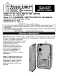
This Time Control with Freeze Protection is
designed to automatically control as well as
protect the Pool/Spa equipment and plumbing
against freeze damage. The Control, if wired
according to instructions, turns ON/OFF the
Filter Pump on a daily schedule and also turns
ON the Filter Pump when the air temperature
(where this Control is located) drops below the
temperature set by the thermostat dial
(between 32˚F and 45˚F). Nevertheless, the
control is not intended to be a substitute for
insulation, coverings or maintenance.
It is self-contained in an indoor-outdoor, beige,
rainproof enclosure and designed to operate
on 240 Volt, 60 cycle only.
Model PF1102MT is a mechanism only,
functions just like Model PF1102T and
fits (snaps into) any Intermatic Pool
Panel, Models T10000R, T30000R or
T40000R Series.
IMPORTANT SAFETY INSTRUCTIONS
When installing and operating this Product and other associated equipment, basic safety precautions should always be
followed.
1. This Control must be installed by a qualified person, according to National and Local Electrical Codes.
2. Install this Control not less than 5 feet (3 meters in Canada) from inside edge of pool and 1 foot (30cm) above ground.USE
COPPER CONDUCTORS ONLY rated minimum 75˚ C.
3. Do not exceed the maximum ratings of individual components, wiring devices, and current carrying capacity of conductors.
4. For Control grounding, bonding, installing and the wiring of underwater lights, refer to Article 680of the National Electrical Code
or Article68 of the Canadian Electrical Code.
5. The Control should not operate any equipment which would cause bodily injury or property damage should it be activated
unexpectedly.
INSTALLATION
open ended (plastic or metal) conduit, about 10 inches
long, installed at bottom of the enclosure. Handle capillary tube with care!
6. TEST INSTALLATION:
a. Turn thermostat dial to its lowest setting and
place crushed ice (in plastic bag) inside capillary
coil of Thermostat.
b. Turn power ON to Control, wait one minute then
slowly turn thermostat dial counterclockwise
until Filter Pump starts.
c. Turn power OFF to Control, remove ice, check
wiring, reinstall front plate.
d. Turn power ON to Control and set Timer and the
Thermostat, see OPERATION instructions on
page 3.
1. Select the proper outdoor location for the Control
and prepare the necessary conduit run(s) required by
the installation layout.
2. Hang enclosure on a flat vertical surface or other
support, using hardware suitable for the purpose.
3. Properly terminate conduits at both ends and pull-in
the conductors (Min.75˚C Rated) as specified by the
installation layout.
4. Follow wiring diagram on page 4 of this manual and
make LINE and LOAD (Pump) connections as shown.
The LINE connections are Black and Red. Connect
LOAD (Filter Pump) to Blue and Yellow leads. Make
sure the installation is properly grounded.
5. If the Control is installed in location where it is
exposed to direct sun most of the day, extend 8 inches
of the copper capillary tube of the thermostat into an
INSTALLATION - MODEL PF1102MT
1. Install mechanism in any Intermatic Pool Panel with
only one Time Switch by snapping it into the unused
mounting bracket, furnished with the Panel.
SETTING / OPERATING INSTRUCTIONS
TO SET ELECTRONIC FILTER TIMER, follow instructions on page 3. The length of the daily
filtration/heating cycle depends on many variables such as size, shape, and geographic location of the
pool, water chemistry, type of pool equipment, usage and season of year. If not sure, contact your local
pool service professional for advice.
TO SET THERMOSTAT, turn dial to desired temperature between 32˚F and 45˚F. Remember, many
variables,such as the location of this Control, the location of the pool or spa, the location and insulation
of the plumbing, etc., must be considered before selecting the “turn ON” temperature of the Filter Pump.
Your local pool service professional is the best source of information. The Thermostat is factory set to
turn OFF the Filter Pump when the ambient temperature rises 5˚ F above its set point.
2
Programming Instructions
OPERATION
(CONT.)
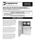
To Set or Change the Time of Day: To clear entire
memory, press P key. Hold down the CLOCK key
while pressing either the HOUR or MINUTE keys.
Continue pressing until the desired number is
shown. Then simply lift finger off the CLOCK key
to set.
To Set Program (ON/OFF times): Press TIMER
key once to enter into program mode. Display will
show “1 ON-- --”. Press the HOUR key and then
the MINUTE key to select the desired first ON
time. Press TIMER key once. Display will show “1
OFF-- --”. Repeat previous step to select the
desired first OFF time. Repeat the entire
sequence to complete up to eight total ON/OFF
times as desired. When programming is done,
press the CLOCK key then the SELECT key
repeatedly until the indicator bar is above the
word “AUTO”.
To Review Program: Press TIMER key repeatedly. When done, press CLOCK key to return to
the time of day.
To Cancel/Change Part of the Program: Press
TIMER key repeatedly until the particular On or
OFF time appears. Set new ON or OFF time.
Display
Reset port
to cancel all
prior settings
Indicator LED “ON”
when connected to
power source and
contacts are closer.
ON/AUTO/OFF
Select Key
Function Keys
To Override Automatic Operation Permanently:
Press SELECT key to move indicator bar to the
desired ON or OFF position. NOTE: Timer will not
resume automatic operation until indicator bar is
repositioned above the word AUTO.
To Override the Automatic Operation one time:
Press OVR. key.
NOTE: Timer will resume automatic operation
with the next opposite set-point.
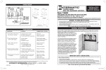
SYMPTOM
1. Blank Timer Display
2. Timer will not respond to
programming
3. Timer will not function as
programmed
4. Pump is ON at all times
5. Filter Pump will not start
when temp.is below 32˚F.
TROUBLESHOOTING
CAUSE(S)
CORRECTIVE ACTION
Discharged battery
Defective timer
Replace battery
Replace timer
Timer is not in “AUTO” mode
Press SELECT key and move
indicator bar over to AUTO
Memory is full
Timer is in Permanent “ON” mode
Defective timer
Defective relay
Defective thermostat
Defective relay
Faulty wiring
3
Press P to clear memory
See above.
Replace timer
Replace relay
Replace thermostat
Replace relay
Check wiring
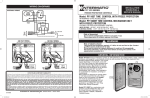
WIRING DIAGRAMS
LINE 2
LINE 1
1 2
COM.
N.C.
N.O.
3 4 5
MEMORY
HOLD-UP
BATTERY
240V
SUPPLY
LIMITED ONE YEAR WARRANTY
If within one (1) year from the date of purchase, this product fails due to a defect in workmanship, Intermatic Incorporated will repair or replace it, at its sole option, free of charge.
This warranty s extended to the original household purchaser only and is not transferable.
This warranty does not apply to: (a) damage to units caused by accident, dropping, or abuse
in handling, acts of God or any negligent use; (b)units which have been subject to
unauthorized repair, opened, taken apart or otherwise modified; (c) units not used in
accordance with instructions; (d) damages exceeding the cost of the product; (e) sealed lamps
and/or lamp bulbs, LED's and batteries; (f) the finish on any portion of the product. such as
surface and/or weathering, as this is considered normal wear and tear, (g) transit damage,
initial installation costs, removal costs, or reinstallation costs.
INTERMATIC INCORPORATED WILL NOT BE LIABLE FOR INCIDENTAL OR
CONSEQUENTIAL DAMAGES. SOME STATES DO NOT ALLOW THE
EXCLUSION OR LIMITATION OF INCIDENTAL OR CONSEQUENTIAL
DAMAGES, SO THE ABOVE LIMITATION OR EXCLUSION MAY NOT APPLY TO
YOU. THIS WARRANTY IS IN LIEU OF ALL OTHER EXPRESS OR IMPLIED
WARRANTIES. ALL IMPLIED WARRANTIES, INCLUDING THE WARRANTY OF
MERCHANTABILITY AND THE WARRANTY OF FITNESS FOR A PARTICULAR
PURPOSE,ARE HEREBY MODIFIED TO EXIST ONLY AS CONTAINED IN THIS
LIMITED WARRANTY, AND SHALL BE OF THE SAME DURATION AS THE
WARRANTY PERIOD STATED ABOVE. SOME STATES DO NOT ALLOW
LIMITATIONS ON THE DURATION OF AN IMPLIED WARRANTY, SO THE ABOVE
LIMITATION MAY NOT APPLY TO YOU.
This warranty service is available by either (a) returning the product to the dealer
from whom the unit was purchased, or (b) mailing the product, along with proof of
purchase, postage prepaid to the authorized service center listed below. This
warranty is made by: Intermatic Incorporated/After Sales Service/7777 Winn Rd.,
Spring Grove, Illinois 60081-9698/815/675/7000 http://www.intermatic.com Please
be sure to wrap the product securely to avoid shipping damage.
Because of our commitment to continuing research and improvements, Intermatic Incorporated reserves the right to make
changes, without notice, in the specifications and material contained herein and shall not be responsible for any damages, direct
or consequential, caused by reliance on the material presented.
158PF12653
INTERMATIC INCORPORATED,
4
SPRING GROVE, IL 60081-9698