1
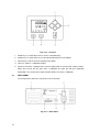
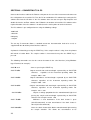
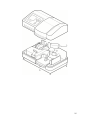
Model 6305
Spectrophotometer
Operating Manual
635 015 REV B/06-14
2
Safety
Please read this information carefully prior to installing or using this equipment.
1. The 63 series spectrophotometers are designed for operation by trained personnel who
are aware of the principles and applications involved. For further help and advice please
visit www.jenway.com
2. The spectrophotometer is a sensitive electronic and optical instrument designed for use in
a laboratory environment. Careful adherence to the installation instructions must be
observed. If in doubt contact a relevant and competent authority for advice before
proceeding.
3. In addition to observing the instructions detailed in the Operating Manual and Service
Manual for this instrument all installation, operating and service personnel must be aware
of, and employ, a safe system of work.
4. Voltage levels hazardous to life are present in this instrument, for personal safety only
trained engineers aware of the risk and avoidance of electric shock should remove
protective covers from the instrument.
5. This instrument is designed for minimal maintenance, which must be carried out carefully
following the procedures detailed in this manual. All safety instructions in these
procedures, as well as those defined locally for the area or environment where the work
is being carried out must be observed.
6. Other than for those items defined in the maintenance procedures herein there are no
user serviceable items in this instrument. Removal of covers and attempted adjustment
or service by unqualified personnel will invalidate any warranty and incur additional
charges for repair.
7. Reference should always be made to the Health and Safety Data for any chemicals or
reagents used. All available information, advice and warnings on the handling, storage,
use and disposal of such must be carefully observed. When not available this data must
be requested from the supplier before proceeding in any way.
8. It is important that good laboratory practice is observed when handling samples,
chemicals, reagents and ancillary equipment in order to carry out measurement and
analysis with this instrument. Suitable safety and personal protective equipment must
be used at all times.
9. If it is suspected that safety protection has been impaired in any way, the
spectrophotometer must be made inoperative and secured against any intended
operation. The fault condition must be reported to the appropriate servicing authority.
In all such reports the model number and serial number of the spectrophotometer must
be quoted.
Sécurité
Ces informations sont importantes ; veuillez les lire avec attention avant d'installer ou
d'utiliser l'instrument.
1. Les spectrophotomètres de la série 63 sont conçus pour être utilisés par du personnel
formé qui connaît les principes et les applications concernés. Pour obtenir de l'aide et
des conseils supplémentaires, merci de consulter le site Internet www.jenway.fr
2. Le spectrophotomètre est un instrument électronique et optique sensible conçu pour être
utilisé en laboratoire. Les instructions d'installation doivent être scrupuleusement
3
respectées. En cas de doute, contactez une personne compétente afin d'obtenir des
conseils avant de procéder à l'installation.
3. En plus de suivre les instructions détaillées des manuels d'utilisation et d'entretien de cet
instrument, tout le personnel impliqué dans l'installation, le fonctionnement et l'entretien
doit connaître et utiliser un système de travail sûr.
4. Des niveaux de tension à risque sont présents dans cet instrument. Pour la sécurité du
personnel, seuls des ingénieurs formés conscients du risque et de la nécessité d'éviter
les chocs électriques peuvent enlever les capots de protection de l'instrument.
5. Cet instrument est conçu pour une maintenance minimale qui doit être effectuée avec
soin en suivant les procédures détaillées dans ce manuel. Toutes les instructions de
sécurité listées dans ces procédures, ainsi que celles définies localement pour la zone
ou l'environnement dans lequel le travail doit être réalisé, doivent être respectées.
6. Hormis les éléments définis dans les procédures de maintenance, il n'existe aucun
élément dans cet instrument qui peut être réparé par l'utilisateur. L'enlèvement des
capots et les tentatives de réglage ou d'entretien par du personnel non-qualifié annuleront
toute garantie et entraîneront des frais supplémentaires de réparation.
7. Il est nécessaire de toujours consulter les données relatives à la santé et à la sécurité
de chaque produit chimique ou réactif utilisé. Tous les conseils, informations et
avertissements disponibles concernant la manipulation, le stockage, l'utilisation et
l'élimination de ces produits chimiques doivent être respectés soigneusement.
Lorsqu'elles ne sont pas disponibles, ces données doivent être demandées dans tous les
cas au fournisseur avant de poursuivre.
8. Il est important que de bonnes pratiques de laboratoire soient respectées lors de la
manipulation d'échantillons, de produits chimiques, de réactifs et d'équipements
auxiliaires afin de réaliser des mesures et des analyses avec cet instrument. Des
équipements de protection individuels et de sécurité adaptés doivent être utilisés à
tout moment.
9. Si une protection de sécurité est susceptible d'être détériorée, le spectrophotomètre doit
être mis hors service et sécurisé pour éviter toute utilisation prévue. L'état défectueux
doit être signalé à l'autorité en charge de la maintenance. Le numéro du modèle et le
numéro de série du spectrophotomètre doivent être indiqués dans tous les rapports.
Sicherheit
Dies sind wichtige Informationen, bitte lesen Sie sie vor Installation oder Verwendung
dieses Geräts sorgfältig durch.
1. Die Spektrophotometer der 63-Serie sind für den Betrieb durch geschultes Personal,
das über die entsprechenden Prinzipien und Anwendungen Bescheid weiß, vorgesehen.
Weitere Hilfe und Hinweise finden Sie auf www.jenway-equipment.de
2. Ein Spektrophotometer ist ein empfindliches elektronisches und optisches Instrument,
das für die Verwendung in Laboren vorgesehen ist. Die Installationsanweisungen sind
genau zu beachten. Wenden Sie sich im Zweifelsfall an die jeweils zuständige Stelle,
bevor Sie fortfahren.
3. Neben der Befolgung der Anweisungen des Betriebshandbuchs und des
Wartungshandbuchs für dieses Gerät muss sämtliches Installations-, Betriebs- und
Wartungspersonal über ein sicheres Arbeitssystem informiert sein und dieses
anwenden.
4. In diesem Gerät herrschen lebensgefährliche Spannungspegel, aus Sicherheitsgründen
dürfen nur geschulte Techniker, die über die Gefahr und Vermeidung von
Stromschlägen informiert sind, Schutzabdeckungen vom Gerät entfernen.
4
5. Dieses Gerät ist für minimale Wartungsarbeiten ausgelegt, die unter Einhaltung der in
diesem Handbuch dargelegten Verfahren sorgfältig durchzuführen sind. Alle
Sicherheitsanweisungen dieser Verfahren sowie die örtlich festgelegten Anweisungen für
das Gebiet oder Umfeld, in dem die Arbeit ausgeführt wird, sind einzuhalten.
6. Außer der in den Wartungsverfahren in diesem Handbuch angegebenen Teile gibt es in
diesem Instrument keine Teile, die vom Benutzer zu warten sind. Die Entfernung von
Abdeckungen sowie der Versuch der Einstellung oder Wartung durch unqualifiziertes
Personal führen dazu, dass die Garantie ungültig wird und können zusätzliche
Reparaturkosten nach sich ziehen.
7. Die Angaben zum Gesundheitsschutz und zur Arbeitssicherheit für die verwendeten
Chemikalien bzw. Reagenzien sind jederzeit zu berücksichtigen. Sämtliche verfügbaren
Informationen, Hinweise und Warnungen in Bezug auf die Handhabung, Lagerung,
Verwendung und Entsorgung dieser Stoffe sind genau zu befolgen. Falls diese
Informationen nicht verfügbar sind, müssen sie vom Lieferanten angefordert werden,
bevor die Arbeiten fortgesetzt werden.
8. Es ist wichtig, dass bei der Handhabung von Proben, Chemikalien, Reagenzien und
Hilfsgeräten zur Durchführung von Messungen und Analysen mit diesem Instrument die
gute Laborpraxis befolgt wird. Es ist jederzeit eine geeignete Sicherheitsausrüstung
und persönliche Schutzausrüstung zu verwenden.
9. Falls vermutet wird, dass der Sicherheitsschutz auf irgendeine Weise beeinträchtigt
wurde, ist das Spektrophotometer außer Betrieb zu setzen und gegen den Betrieb zu
sichern. Die Störung ist der entsprechenden Wartungsstelle zu melden. In diesen
Berichten ist die Modellnummer und die Seriennummer des Spektrophotometers
anzugeben.
Seguridad
Información importante que debe leer atentamente antes de instalar o utilizar este
instrumento.
1. Los espectrómetros de la serie 63 se han concebido para ser utilizados por personal
con formación que conozca los principios y las aplicaciones que entrañan. Si necesita
más ayuda o indicaciones, diríjase a www.jenway.com
2. El espectrómetro es un instrumento electrónico y óptico de gran sensibilidad destinado a
entornos de laboratorio. Deben seguirse atentamente las instrucciones de instalación. En
caso de duda, consulte a la autoridad competente y pertinente antes de continuar.
3. Aparte de cumplir las instrucciones detalladas en el Manual de funcionamiento y el
Manual de servicio de este instrumento, todo el personal de instalación, manejo y servicio
debe conocer y aplicar un sistema seguro de trabajo.
4. Este instrumento presenta niveles de tensión peligrosos; por motivos de seguridad
personal, las tapas protectoras del instrumento debe ser retiradas únicamente por
técnicos debidamente cualificados que conozcan los riesgos y sepan evitar las
descargas eléctricas.
5. Este instrumento ha sido diseñado con requisitos mínimos de mantenimiento, que debe
realizarse con cuidado de acuerdo con los procedimientos detallados en este manual.
Deben cumplirse todas las instrucciones de seguridad de estos procedimientos, así como
las que se establezcan localmente para la zona o el entorno donde se esté realizando el
trabajo.
6. A excepción de los elementos indicados en los procedimientos de mantenimiento de este
manual, este instrumento no contiene piezas que necesiten ningún tipo de
mantenimiento por el usuario. La retirada de las tapas y cualquier intento de ajuste o
5
mantenimiento por parte de personal no cualificado dará lugar a la invalidación de la
garantía y podría causar gastos adicionales de reparación.
7. Deben consultarse siempre los datos sobre salud y seguridad de los productos
químicos o reactivos empleados. Debe leerse atentamente toda la información, los
consejos y las advertencias existentes sobre la manipulación, el almacenamiento, el uso
y la eliminación de los mismos. Si no se dispone de información, deberá solicitarse al
proveedor antes de continuar.
8. Es importante adoptar buenas prácticas de laboratorio cuando se manipulen muestras,
productos químicos, reactivos y equipos auxiliares para realizar medidas y análisis con
este instrumento. Se deben utilizar siempre equipos de seguridad y protección
personal.
9. Ante la sospecha de que alguna medida de seguridad se haya visto de algún modo
comprometida, el espectrómetro deberá dejarse inutilizado, así como garantizarse que
nadie pueda utilizarlo. Debe informarse de cualquier fallo al responsable de servicio
pertinente. En todos los informes, deben indicarse el número de modelo y el número
de serie.
Sicurezza
Queste informazioni sono importanti; si prega di leggerle attentamente prima di installare
o utilizzare lo strumento.
1. Gli spettrofotometri della serie 63 sono progettati per essere utilizzati da personale
qualificato che conosce i principi e le applicazioni ad essi collegati. Per ulteriori
informazioni e per assistenza visitare il sito internet www.jenway.com
2. Lo spettrofotometro è uno strumento ottico elettronico sensibile progettato per l'uso in
laboratorio. Seguire minuziosamente le istruzioni di installazione. In caso di dubbi
rivolgersi all'autorità competente appropriata per una consulenza prima di procedere.
3. Oltre ad osservare le istruzioni indicate nel Manuale di funzionamento e manutenzione
del presente strumento, tutto il personale addetto all'installazione, funzionamento e
manutenzione deve conoscere e implementare un sistema di lavoro sicuro.
4. Questo strumento utilizza livelli di tensione pericolosi, pertanto per la sicurezza personale
solo i tecnici qualificati che conoscono i rischi e come evitare le scosse elettriche
possono rimuovere le coperture protettive dallo strumento.
5. Questo strumento è progettato per necessitare di una manutenzione minima, che però
deve essere eseguita con cura seguendo le procedure indicate in questo manuale.
Rispettare tutte le istruzioni per la sicurezza presenti in queste procedure, nonché quelle
definite a livello locale per l'area o l'ambiente in cui viene eseguito il lavoro.
6. Ad esclusione delle parti indicate nelle procedure di manutenzione contenute in questo
manuale, l'apparecchiatura non contiene componenti che possano essere riparati
dall'utente. La rimozione di coperture ed eventuali tentativi di regolazione o riparazione
da parte di personale non qualificato renderanno nulla qualsiasi garanzia e genereranno
dei costi aggiuntivi per la riparazione.
7. Fare sempre riferimento ai dati sulla salute e la sicurezza per tutte le sostanze chimiche
o reagenti utilizzati. Osservare attentamente tutte le informazioni, i consigli e le
avvertenze disponibili sulla loro manipolazione, conservazione, utilizzo e smaltimento.
Qualora tali dati non siano disponibili, richiederli al fornitore prima di procedere in
qualsiasi modo.
8. È importante che vengano osservate le buone pratiche di laboratorio quando si
manipolano campioni, sostanze chimiche, reagenti e apparecchiature accessorie per
6
eseguire misurazioni e analisi con questo strumento. Attrezzature idonee per la
protezione personale e la sicurezza vanno utilizzate in ogni circostanza.
9. Se si sospetta che la protezione della sicurezza sia stata compromessa in qualsiasi
modo, disattivare e rendere inutilizzabile lo spettrofotometro. La condizione di guasto
deve essere comunicata al responsabile della manutenzione appropriato. Tale
comunicazione deve sempre comprendere il numero di modello e il numero di serie
dello spettrofotometro.
7
Contents
SECTION 1 - Introduction .......................................................................................... 9
1.1
1.2
INSTRUMENT DESCRIPTION............................................................................................. 9
INSTRUMENT SPECIFICATION.......................................................................................... 9
SECTION 2 – Installation ......................................................................................... 10
2.1
2.2
2.3
2.4
2.5
2.6
UNPACKING....................................................................................................................... 10
INSTALLATION .................................................................................................................. 10
DISPLAY ............................................................................................................................. 11
CONTROLS ........................................................................................................................ 11
REAR PANEL ..................................................................................................................... 12
SAMPLING ......................................................................................................................... 13
SECTION 3 – Theory and Practice of Spectroscopy Measurements ....................... 14
3.1
3.2
3.3
THEORY OF SPECTROSCOPY MEASUREMENT .......................................................... 14
SPECTROSCOPY MEASUREMENT ................................................................................. 15
GOOD PRACTICE GUIDELINES ....................................................................................... 16
SECTION 4 – PHOTOMETRICS MEASUREMENTS .............................................. 18
4.1
4.2
TRANSMISSION MEASUREMENT MODE ....................................................................... 18
ABSORBANCE MEASUREMENT MODE .......................................................................... 18
SECTION 5 – CONCENTRATION MEASUREMENTS ............................................ 19
5.1
5.2
USING A KNOWN STANDARD ......................................................................................... 19
USING A KNOWN FACTOR .............................................................................................. 19
SECTION 6 – CONNECTING TO A PC ................................................................... 20
6.1
6.2
RS232 Output ..................................................................................................................... 21
Recorder Output ................................................................................................................. 22
SECTION 7 – Accessories and Spare Parts ............................................................ 23
7.1
7.2
OPTIONAL ACCESSORIES............................................................................................... 23
SPARES ............................................................................................................................. 23
SECTION 8 – Maintenance and Service .................................................................. 24
8.1
8.2
8.2.1
8.3
ROUTINE MAINTENANCE ................................................................................................ 24
LAMP REPLACEMENT ...................................................................................................... 24
Xenon Flash Lamp Module Replacement .......................................................................... 24
SERVICE ............................................................................................................................ 26
SECTION 9 – Troubleshooting ................................................................................. 27
9.1
9.2
ERROR CODES ................................................................................................................. 27
TECHNICAL SUPPORT ..................................................................................................... 27
SECTION 10 – Declaration of Conformity ................................................................ 28
8
SECTION 1 - Introduction
1.1
INSTRUMENT DESCRIPTION
The 6305 spectrophotometer is suited to a wide range of applications in education, quality control,
environmental and clinical analysis. This model is a UV/visible spectrophotometer covering a
wavelength range from 198nm to 1000nm, with measurement modes for absorbance, %
transmittance and concentration. It has full interfacing capability for Analogue output and serial
(RS232) interfacing. The optical system is independently housed and isolated with lenses to give
maximum protection from environmental contamination. Combined with a mechanically rigid
structure, this model provides a system with fast warm-up, low drift and high reliability.
1.2
INSTRUMENT SPECIFICATION
6305
Wavelength
Range
Resolution
Accuracy
Spectral bandwidth
Photometrics
Transmittance
Absorbance
Accuracy
Resolution
Stability
Concentration
Range
Resolution
Calibration
Units
Factor
Standard
Other
Beam height
Light source
Outputs
Power
Size (w x d x h)
Weight
198 to 1000nm
1nm
± 2nm
8nm, 6nm over the UV range
0 to 199.9%
-0.300 to 1.999A
±1%T, ±0.01Abs at 1.000 Absorbance
0.1%T, 0.001A
1%/hr after 20 minute warm up
-300 to 1999
1/0.1
Blank with a single standard or factor
no units, %, ppm, M, g/l, mg/l
0.1 to 9999
0.1 to 1999
15mm
Xenon flash lamp module
Analogue, RS232
<50W
365 x 272 x 160mm
6kg
9
SECTION 2 – Installation
2.1
UNPACKING
Remove the 6305 from the packaging and ensure the following items are included:
1. Model 6305 spectrophotometer
2. Required power cable either UK mains lead moulded plug (HH179(S)), EU mains lead
moulded plug (HH180(S)), or US mains lead moulded plug (FCABLEUS)
3. Pack of 100 disposable plastic visible wavelength cuvettes (060 084)
4. Jenway 63-zero PC software (635 100) and interface cable (013 210) model 6300 only
5. Instruction manual (635 015)
6. Jenway Foreign Manual CD (JENMANCD)
7. Optional accessories (as ordered)
2.2
INSTALLATION
Model 6305 is supplied ready to use.
The unit should be placed on a clean flat surface which is free from drafts and vibrations. The unit
is designed for operation on 115V to 230V AC input at 50 to 60Hz. The standard 2 metre cable
supplied with the unit is fitted with an IEC type connector which can be plugged directly into the
POWER IN socket on the rear panel. The unit should be positioned within 1.5 metres of an
earthed mains supply.
The mains fuse is housed within the POWER IN socket. When replacing the fuse the unit must be
disconnected from the mains supply. The fuse rating is 2A ‘F’ (fast blow type). In the event of the
fuse failing after replacement it is advisable to consult with Bibby Scientific Service or your
distributor before proceeding further.
It is possible to switch the voltage between 230V and 115V. When changing the voltage please
ensure the fuse rating is correct. Before attempting to change the voltage disconnect the
instrument from the mains supply. Withdraw the fuse holder from the power input socket and
remove the fuse. Extract the grey fuse retainer and rotate so that the correct voltage is visible
through the aperture in the fuse holder. Replace the fuse retainer in its holder, fit the correct fuse
and push assembly back into the power input socket. For further information please refer to the
service manual.
Connect the power supply unit to the power inlet socket on the rear panel of the instrument and
connect to the mains socket. Turn the power on at the mains and switch the instrument on using
the power switch on the rear of the instrument. DO NOT open the sample chamber door during
initialisation.
The instrument will automatically re-align the monochromator using spectral peaks associated
with the xenon flash lamp. During this initialisation, the instrument displays CAL on the primary
10
display before displaying the main measurement screen. Please note that the instrument will go to
the last wavelength and measurement mode used.
2.3
DISPLAY
This spectrophotometer has an LCD display:
Fig. 2.3.1 – Display
1. Primary display area – Transmission, Absorbance, Concentration
2. Primary display adjust annunciator
3. Secondary display area – Wavelength, Factor
4. Primary display units
5. Secondary display annunciator
6. Operation with PC
7. Menu options - %T, ABS, CONC, FACTOR, UNITS
8. Menu pointers (for above)
2.4
CONTROLS
The keypad used for this model enables an easy and effective way of navigating the
different measurement modes. The arrow keys can be used to move between modes and
to adjust wavelengths, factors, concentration and units. The main menu screen and
surrounding keypad is displayed below:
11
Fig. 2.4.1 – Controls
1. Arrow Keys: Used to adjust values on the selected display
2. Arrow Keys: Used to move the cursor horizontally between menu options
3. Return Key: Used to select the display menu option
4. CAL Key: Initiates a calibration routine
5. Print Key. Provides a printout of the current reading with an incremental sample number.
When pressed for the first time after a calibration the print out will give calibration
information. The incremental sample number will be reset after a calibration.
2.5
REAR PANEL
The image below shows the rear panel on the instrument:
Fig. 2.5.1 – Rear Panel
12
1. Lamp access panel
Allows access to lamp when replacement is necessary (6300 and
6320D only) Refer to section 8.2 for xenon lamp replacement (6305 only)
NOTE: The lamp access panel and all ventilation slots must NOT be covered or
obstructed at any time.
2.6
2. Power switch
On/off switch for the unit
3. Power in socket
IEC type connection socket for mains cable
4. Output sockets
Analogue output
5. RS232 serial port
Connection to a PC
SAMPLING
Model 6305 is supplied with a 10mm cuvette holder. Other accessories can be fitted (refer to
section 7).
13
SECTION 3 – Theory and Practice of Spectroscopy Measurements
3.1
THEORY OF SPECTROSCOPY MEASUREMENT
UV-visible spectroscopy is the measurement of the absorbance of light at a specific wavelength in
a sample. This is used to identify the presence and concentration of molecular entities within the
sample. The Beer-Lambert law is used to relate the absorption of light to the properties of the
sample through which the light is travelling through. The Beer-Lambert law states that:
is the absorbance
A
-1
-1
is the molar absorption coefficient (l mol cm )
-1
c
is the concentration (mol l )
l
is the path length (cm)
This law shows that absorbance is linear to concentration but this is only true for low
concentrations. For absorbance levels above 3 the concentration starts to move away from the
linear relationship.
Transmittance is the proportion of the light which passes through the sample:
Where:
Io
It
lo
is the incident light
lt
is the transmitted light
l
is the path length
l
Therefore:
T = It
Io
Absorbance is inversely related to transmittance:
A = log 1
T
14
3.2
SPECTROSCOPY MEASUREMENT
There are four main components of a spectrophotometer. These are a light source to emit a high
and constant amount of energy over the full wavelength range; a method for separating the light
into discreet wavelengths; a sample holder and a light detector.
The optical layout of the 6305 spectrophotometer is shown below:
Figure 3.2.1 – Diagram of light path
The light from the xenon lamp is focused onto the grating, with 1200 lines per millimeter, which
separates the light into discreet wavelengths. The diffracted spectrum of light then passes through
a further slit and lens arrangement before passing through the sample in the sample chamber
from left to right. The light which is not absorbed by the sample is transmitted through a collecting
lens and onto the signal detector. The photo-diode detector used is mounted directly onto the
detector PCB and is used to calculate the % transmittance. The result is displayed either as %
transmittance or absorbance on the instrument display.
15
3.3
GOOD PRACTICE GUIDELINES
1. For optimum performance all spectrophotometers should be sited in a clean, dry, dust
free atmosphere. When in use ambient temperature and light levels should remain as
constant as possible.
2. If required adherence to Standard Operating Procedures (SOP) and Good Laboratory
Practice (GLP) should be monitored with regular calibration checks and a suitable
Quality Control (QC) programme.
3. The sample chamber lid must be fully closed during measurement and before any
readings are recorded or printed.
4. The correct selection of sample containers is imperative for accurate and
reproducible results:
a) Check that the material of the sample container is compatible with the
wavelengths to be used for measurement. In general glass can only be used
down to 360nm or 320nm depending on quality. Standard plastic cuvettes can be
used down to 320nm. Special UV versions can be used down to 260nm. Below
this level quartz cuvettes must be used. NOTE: the plastic cuvettes supplied
with the unit are not suitable for use below a wavelength of 320nm.
b) Plastic disposable cuvettes should only be used ONCE.
c) Glass cuvettes should be thoroughly cleaned after use. Discard when scratches
become evident on optical surfaces.
d) Care should be taken when selecting semi-micro or micro cuvettes. The cuvette
window on the inner chamber (the area filled with sample) must be wider than the
aperture in the sample holder or light will reach the detector without passing
through the sample. In this case, semi-micro or micro cuvettes with self-screening
black surrounds must be used or, alternative holders for these cuvettes should be
used.
e) Glass test tubes and other sample tubes should be used with care. Where
possible, matched tubes should be used and any index mark set to the correct
position before measurements are made.
f)
Ensure any sample containers used are compatible with the constituents of both
the samples and standards they are to hold. Plastic cuvettes are not compatible
with organic solvents.
g) All sample containers must be handled with care; by the top, bottom and nonoptical surfaces only. Any finger marks evident must be removed by a suitable
cleaning process.
16
h) Flow-through cuvettes must be selected with care and consideration for the
sample type, sample volume, pumping system, rinse, sample and waste handling
to be used.
5. Samples and standards should not be stored in open cuvettes or sample containers
as evaporation will change the value and lead to staining of the walls which may be
irreversible. If stored in stoppered and sealed cuvettes, they should be filled with little
or no air space and the values regularly checked against a reference standard or
quality control material.
6. Samples should be allowed to equilibrate to ambient temperature before
measurement (unless a suitable temperature controlled sample holder is in use).
Temperature change during measurement may cause air bubbles to form on the
walls of the sample holder. This is a common cause of drift during measurement.
7. In the preparation of samples and standards high grade borosilicate glass and AR
grade chemicals and reagents must be used. Good quality deionised water or other
suitable solvents must be used for dissolving or diluting samples, chemicals and
reagents.
8. All measurements require calibration to a blank, for maximum accuracy this should be
prepared with care using the same deionised water or solvent used for dissolving or
diluting the sample. Where reagents are added to the sample to produce a colour
proportional to its concentration a ‘sample based’ blank should be used. In this case
the blank should consist of all reagents or chemicals to be used, except the sample
which will produce the colour to be measured.
9. Deviations from the Beer-Lambert Law may occur at high and low concentrations
giving non-linear response during sample concentration measurements. For all new
methods a linear range should be defined by the preparation of a calibration curve.
10. Cuvettes and sample holders must be filled to a minimum level which covers the light
path. All Jenway spectrophotometers have a beam height of 15mm.
11. The instrument must be calibrated to zero absorbance/100% transmittance prior to
taking readings.
17
SECTION 4 – PHOTOMETRICS MEASUREMENTS
The 6305 can perform simple measurements of % transmittance or absorbance. The sample is
measured at one wavelength and at one point in time.
4.1
TRANSMISSION MEASUREMENT MODE
To select % Transmittance use the LEFT or RIGHT arrow keys to move the cursor to the %T
indicator on the menu bar (refer to figure 2.3.1). The primary display will show the transmittance
with %T units. To adjust the wavelength use the UP and DOWN arrow keys.
The calibration must be performed at the same wavelength at which the sample will be measured.
Insert a cuvette containing the blank (clear) solution into the sample chamber and close the
instrument lid. Press the CAL key. The instrument will perform a zero % transmission calibration
followed by a 100% transmission calibration. An internal shutter is automatically activated to
perform the zero % setting and this part of the routine is therefore independent of the solution in
the light path).
Once the calibration has been performed a sample can be measured. Remove the cuvette
containing the blank solution and place a cuvette containing the sample to be measured in the
sample holder. Close the instrument lid and the % transmittance result will be shown on the
screen.
Subsequent samples can be measured in the same way. If the wavelength is adjusted between
sample measurements then the instrument must be calibrated again before more samples can be
measured.
4.2
ABSORBANCE MEASUREMENT MODE
To select absorbance use the LEFT or RIGHT arrow keys to move the cursor to the ABS indicator
on the menu bar (refer to figure 2.3.1). The primary display will show the absorbance with ABS
units. To adjust the wavelength use the UP and DOWN arrow keys.
The calibration must be performed at the same wavelength at which the sample will be measured.
Insert a cuvette containing the blank (clear) solution into the sample chamber and close the
instrument lid. Press the CAL key. The instrument will perform a zero % transmission calibration
followed by a 0.000 Absorbance calibration. An internal shutter is automatically activated to
perform the zero % setting and this part of the routine is therefore independent of the solution in
the light path.
Once the calibration has been performed a sample can be measured. Remove the cuvette
containing the blank solution and place a cuvette containing the sample to be measured in the
sample holder. Close the instrument lid and the absorbance result will be shown on the screen.
Subsequent samples can be measured in the same way. If the wavelength is adjusted between
sample measurements then the instrument must be calibrated again before more samples can be
measured.
18
SECTION 5 – CONCENTRATION MEASUREMENTS
The concentration measurement mode enables simple measurements of concentration to be
performed. In this measurement mode it is possible to calibrate against a standard of a known
concentration or use a known factor. The sample is measured at one wavelength at one point in
time.
To select concentration use the LEFT or RIGHT arrow keys to move the cursor to the CONC
indicator on the menu bar (refer to figure 2.3.1). The primary display will show the concentration
with the selected units. To adjust the wavelength use the UP and DOWN arrow keys.
To select the units use the LEFT or RIGHT arrow keys to move the cursor to the UNITS indicator
on the menu bar (refer to figure 2.3.1). Use the UP and DOWN arrow keys to select ppm, mg/l,
g/l, M, % or blank units. Once the required units have been selected press the RETURN or CAL
key to store the units and return to the concentration measurement mode.
5.1
USING A KNOWN STANDARD
The calibration must be performed at the same wavelength at which the sample will be measured.
Insert a cuvette containing the known concentration standard into the sample chamber and close
the instrument lid. Press the CAL key; the CAL annunciator will flash continuously. Use the arrow
keys to change the concentration to the required value for the standard. Press the CAL or
RETURN key to calibrate the instrument to the standard concentration. The instrument will
calculate the factor for subsequent measurements. If the factor calculated is out of range, then the
instrument will display Err 3 for 2 seconds after the calibration. To view the factor use the LEFT
or RIGHT arrow keys to move the cursor to the xF indicator on the menu bar (refer to figure
2.3.1).
Once the calibration has been performed a sample of unknown concentration can be measured.
Remove the cuvette containing the standard solution and place a cuvette containing the sample
to be measured in the sample holder. Close the instrument lid and the concentration result will be
shown on the screen.
Subsequent samples can be measured in the same way. If the wavelength is adjusted between
sample measurements then the instrument must be calibrated again before more samples can be
measured.
5.2
USING A KNOWN FACTOR
If the factor is known there is no need to calibrate against a known standard. To enter the factor
use the LEFT or RIGHT arrow keys to move the cursor to the xF indicator on the menu bar (refer
to figure 2.3.1). Use the UP and DOWN arrow keys to enter the required factor. Once the required
factor has been entered press the RETURN or CAL key to store the factor and return to the
concentration measurement mode.
19
SECTION 6 – CONNECTING TO A PC
Connect the interface cable to the RS232 serial port on the rear of the instrument and connect to
the serial port on the rear of the PC. Turn the PC on and load the PC software by inserting the PC
software disc into the CD drive. If the PC software does not auto run open My Computer and
double click on the 63-Zero software icon. Follow the instructions to install the PC software to the
required location. Once the software is installed, turn the mains power on to the instrument.
The PC software is pre-configured to run using the following settings:
1200 baud
7 data bits
Odd parity
1 stop bit
The 25 way D connector allows a standard one-to-one interconnection lead to be used, as
supplied with the 40 column printer/interface cable kit.
A printout is initiated by pressing the PRINT key. If the sample number is unity, then the printout
will include a header block. The sample number is incremented every time the PRINT key is
pressed.
The following commands can also be sent to the 6305 via the serial interface (using Windows
HyperTerminal, for example):
ASCII D or d
ASCII T<CR>
Same as pressing the PRINT key
Outputs transmission and wavelength separated by an ASCII TAB
character,
regardless of the instrument operating mode. For
example: 100.0 540
ASCII A<CR>
Outputs absorbance and wavelength separated by an ASCII TAB
character, regardless of the instrument operating mode. For
example: 0.001 540
ASCII C<CR>
Outputs concentration and wavelength separated by an ASCII TAB
character, regardless of the instrument operating mode. For
example: 123.4 540
ASCII V<CR>
Outputs a voltage proportional to the monochromatic light level
passing the sample and wavelength separated by an ASCII TAB
character. For example: 1234.5 540
ASCII Z<CR>
Calibrates a zero absorbance if the dark shutter is open
(SO<CR>command), or zero transmittance if the dark shutter is
closed (SC<CR>command).
ASCII SC<CR>
Closes the dark shutter which blocks monochromatic light entering
the sample chamber. This allows 0% transmittance to be
20
calibrated.
ASCII SO<CR>
Opens the dark shutter which allows monochromatic light to enter the
sample chamber. This allows 100% transmittance (zero absorbance) to
be calibrated. The shutter must be open for normal measurements.
ASCII Gnnn<CR>
Commands the instrument to go to wavelength nnm. For example:
G540<CR> will set the wavelength to 540nm.
ASCII Fxxxx.x<CR>
Sets the concentration factor to xxxx.x. For example: F1000<CR> will set
the factor to 1000.
Note <CR> is an ASCII carriage return character. The last three commands provide an output
which can be readily incorporated into most spreadsheet software packages.
6.1
RS232 Output
The bi-directional RS232 interface is available on the rear panel 25 way D type connector. The
connections are as follows:
TDX 2
– INPUT TO 6305
RXD 3
– OUTPUT FROM 6305
RTS 4
– LINKED TO CTS
CTS 5
– LINKED TO RTS
DSR 6
– OUTPUT FROM 6305
DCD 8
– OUTPUT FROM 6305
DTR 20
– INPUT TO 6305 (must be active)
GND 7
Suggested interconnections are detailed below:
6305
IBM PC XT (25 way “D”)
TDX 2
2 TXD (From PC)
RXD 3
3 RXD (To PC)
RTS 4
4 RTS (From PC)
CTS 5
5 CTS (To PC)
DSR 6
6 DSR (To PC)
DCD 8
8 DCD (To PC)
DTR 20
20 DTR (From PC)
GND 7
7 GND
21
6305
IBM PC XT (9 way “D”)
TDX 2
3 TXD (From PC)
RXD 3
2 RXD (To PC)
RTS 4
7 RTS (From PC)
CTS 5
8 CTS (To PC)
DSR 6
6 DSR (To PC)
DCD 8
1 DCD (To PC)
DTR 20
4 DTR (From PC)
GND 7
5 GND
Note the interface cable kit (542 009) can be used to implement the above interconnections.
6.2
Recorder Output
This is available via the 4mm rear panel sockets. The level is proportional to the displayed
reading, depending on the measurement mode:
Transmission
1mV per 0.1%T
Absorbance
1mV per 0.001ABS
Concentration
1mV per concentration unit
22
SECTION 7 – Accessories and Spare Parts
7.1
OPTIONAL ACCESSORIES
Part Code
634 001
632 001
632 031
630 204
637 071
630 005
630 304
648 001
632 511
033 290
630 028
037 551
543 001
060 287
060 288
542 009
Description of Accessory
4 position manual cuvette holder
Sipper pump, supplied with inlet and outlet tubing (230V/50Hz)
Sipper pump, supplied with inlet and outlet tubing (110V/60Hz)
10x10mm path length cuvette holder
10mm cuvette and 16/24mm test tube holder
10 to 100mm adjustable path length cuvette holder
Micro-cuvette holder
Water heated 10x10mm single cuvette holder
Dual cell holder for 10mm cuvettes and 12.7mm diameter tubes (6320D ONLY)
Storage/carry case (not for use with 6320D)
Dust cover
RS232 to USB converter for use with computer without a serial port
40 Column printer supplied with interface cable, paper roll and ribbon and
universal power supply
Paper roll for printer (quantity 1)
Printer ribbon (quantity 1)
Interface cable kit
7.2 SPARES
Part Code
012 094
630 204
632 511
060 084
HH179(S)
HH180(S)
FCABLEUS
635 100
013 210
016 021
016 025
Description of Spare Part
Xenon Flash Lamp Module (6305)
10x10mm path length cuvette holder
Dual cell holder for 10mm cuvettes and 12.7mm diameter tubes (6320D ONLY)
Pack of 100 disposable plastic visible wavelength 10x10 cuvettes
UK mains lead moulded plug
EU mains lead moulded plug
US mains lead moulded plug
PC software on CD ROM
Serial Lead to connect to PC
Replacement fuse 2A
Replacement fuse 1A
To order spares please contact your local distributor or Bibby Scientific:
E-mail: [email protected]
Tel: +44 (0) 1785 810234
23
SECTION 8 – Maintenance and Service
8.1
ROUTINE MAINTENANCE
Ensure the external surfaces of the unit are clean and free from dust. The sample area should
always be kept clean and any accidental spillage should be wiped away immediately. To give
added protection when not in use, the unit should be disconnected from the mains supply and
covered with the optional dust cover.
The only routine maintenance which maybe required is the replacement of the light source. The
replacement lamp is available from your local distributor or Bibby Scientific (refer to section 7.2 for
spare part codes). Only genuine replacement lamps should be used. Similar lamps may have
different filament configurations or be wavelength restricted for domestic or commercial use and
will give rise to errors if used.
8.2
LAMP REPLACEMENT
8.2.1
Xenon Flash Lamp Module Replacement
Before replacing the lamp disconnect the unit from the mains supply. Access to the xenon flash
lamp module can be gained via removing the top cover of the instrument.
1. Remove the 4 screws located on the underside of the instrument.
2. Lift the top cover clear, taking care not to strain the ribbon cable.
3. Remove the 2 xenon lamp retaining thumb screws.
4. Remove the connector from the rear of the xenon lamp.
5. When replacing the lamp ensure it is pushed fully up into the optics housing before
tightening the thumb screws.
6. Refit the top cover, taking care with the ribbon cable.
7. Refit and tighten the 4 screws located on the underside of the instrument.
8. Reconnect the power supply, turn on the unit and ensure that the lamp is illuminated after
a few seconds.
For further instructions refer to the service manual.
24
25
8.3
SERVICE
Our dedicated service staff are on hand to help in the unlikely event that your Jenway equipment
develops a fault. Please contact them by one of the following means with a clear description of
the problem:
E-mail: [email protected]
Tel: +44 (0) 1785 810475
Fax: +44 (0) 1785 810471
On occasion it may be necessary for your equipment to be sent back to our Service Department
for repair. In this case please contact the Service Department for a reference number which you
should include with your faulty equipment. Please also ensure you include a clear description of
the fault and a completed copy of our Decontamination Certificate. This is available as a
downloadable pdf file at www.jenway.com, or contact us and we will be happy to send you a copy.
Please clearly mark the package for the attention of the Service Department and post to the
following address:
Bibby Scientific Ltd
Beacon Road
Stone
Staffordshire
ST15 0SA
United Kingdom
All replacement parts are guaranteed for 1 year and where ever possible, returned equipment is
turned around in 10 working days.
26
SECTION 9 – Troubleshooting
9.1 ERROR CODES
Refer to the table below to diagnose error codes. If you require further assistance contact Jenway
Help (refer to section 9.2).
Error Code
Err 1
Error Name
Dark cal error
Issue
This error occurs when the 6305 closes the shutter to block
light entering the sample chamber. If the detector output
does not fall to a level normally associated with a dark cal
then this error is indicated. The most likely cause is that the
sample chamber lid is not closed.
Err 2
Light cal error
This error indicates that there is insufficient light to calibrate
to 100%. The most likely cause is that the light at the
selected wavelength is being absorbed by a sample in the
sample chamber.
This error can also be caused if the lamp has failed.
Err 3
Concentration
calibration error
The calculated factor is outside the instrument range.
Recalibrate the instrument using a standard of lower
concentration.
Err 5
Lamp Failure
The instrument is unable to detect a peak signal for
wavelength calibration. Possible causes of this error are that
the lamp has failed or that a sample has been left in the
sample chamber during start-up.
Err 6
Power on self-test
error
Detector signal with the lamp off exceeds the preset
threshold. Possible cause is that the sample chamber lid is
not closed.
Err 7
Power on self-test
error
The instrument is unable to detect the monochromator
reference position sensor. Please contact Bibby Scientific
service or your local distributor.
9.2
TECHNICAL SUPPORT
Jenway have a dedicated Technical Support team made up of experienced scientists who are on
hand to help with any applications advice and questions you may have about our products
and
how to use them. If you require any technical or application assistance please contact the team
at:
E-mail: [email protected]
Phone: +44 (0)1785 810433
27
SECTION 10 – Declaration of Conformity
28
Bibby Scientific Ltd
Bibby Scientific France SAS
Bibby Scientific Ltd. – Singapore
Beacon Road Stone
Staffordshire ST15 0SA
United Kingdom
Tel: +44 (0)1785 812121
Fax: +44 (0)1785 813748
e-mail: [email protected]
www.bibby-scientific.com
ZI du Rocher Vert - BP 79
77793 Nemours Cedex
France
Tel: +33 1 64 45 13 13
Fax: +33 1 64 45 13 00
e-mail: [email protected]
www.bibby-scientific.com
Prudential Tower, Level 26,
30 Cecil Street 049712
Singapore
Tel: +65 6631 2976
Fax: +44 (0) 1785 810405
e-mail: [email protected]
www.bibby-scientific.com
Bibby Scientific Middle East Ltd
Bibby Scientific US Ltd
BPO Box 27842
Engomi 2433
Nicosia Cyprus
Tel: +357 22 660 423
Fax: +357 22 660 424
e-mail: [email protected]
www.bibby-scientific.com
3 Terri Lane Suite 10
Burlington NJ 08016
USA
Tel: 800-225-9243
Fax: 609-589-2571
www.bibby-scientific.com
29