1
OWNER’S MANUAL
CALIFORNIA PROPOSITION 65 INFORMATION
TO CALIFORNIA CUSTOMERS AND
TO CUSTOMERS SELLING DIESEL ENGINE EQUIPMENT
INTO - OR FOR USE IN - CALIFORNIA
Proposition 65, a California law, requires warnings on products which expose
individuals in California to chemicals listed under that law, including certain chemicals
in diesel engine exhaust.
Obligations of Manufacturers of Diesel-Powered Off-Road Equipment.
The California Superior Court has approved either of the following two methods if
compliance with Proposition 65 requirements by manufacturers of off-road equipment
containing diesel engines.
1. On-Equipment Warning.
Place the warning pictured in attachment 1 on all equipment shipped by you into
or for sale in California after January 1, 1996. The warning must be in a location
where it is easily visible to the operator of the equipment when (s)he is operating
the equipment. The warning must be secured to the equipment. If warnings or
operating instructions are provided through a digital display, you may use that
method of providing the warning.
2. Operator Manual Warning.
When the operator manual is next revised or by December 31, 1995, whichever is
earlier, place the warning in attachment 2 in the operator manual. The warning
may be either printed in the manual or on a sticker.
The warning must appear in one of the following locations:
Inside the front cover
Inside the back cover
Outside the front cover
Outside the back cover
As the first page of text
Under either alternative, the warning must appear in the same size, print and format
as the attachment selected or be of an equally conspicuous size and format. If the
warning is provided in an on-screen display, the warning must contain the language
in the attachment and must be provided at the time of or in connection with ignition in
the same manner as other safety warnings electronically communicated on screen.
Obligation of Resellers of Diesel Engines.
This letter must accompany any loose diesel engine sold in California.
Should you have any questions, please call the manufacturer’s representative.
1
ATTACHMENT 1
Warning to Place on Equipment
CALIFORNIA
Proposition 65 Warning
Diesel engine exhaust and some
of its constituents are known to
the State of California to cause
cancer, birth defects, and other
reproductive harm.
ATTACHMENT 2
Warning in the Manual
CALIFORNIA
Proposition 65 Warning
Diesel engine exhaust and some
of its constituents are known to
the State of California to cause
cancer, birth defects, and other
reproductive harm.
CALIFORNIA
Proposition 65 Warning
Diesel engine exhaust and some of the constituents
are known to the State of California to cause cancer,
birth defects, and other reproductive harm.
2
T-630 Recommended Service
-- CAUTION -Before Any Service or Maintenance
• Engine Must Be OFF.
• Set Park Brake and remove key.
• Lock Articulate Safety Lock Bar.
• Engage Auger Safety Catch.
• Do not allow unauthorized or unqualified personnel to operate or
service this machine.
DAILY SERVICE:
1. Grease all fittings except front axle
2. Grease turntable
3. Check engine oil level *
4. Check engine air breather indicator
5. Check engine water (with engine cold)
6. Check auger seal and tighten if necessary
7. Check chain tensions (1/2" play) of:
a. Turntable
b. Turntable swing motor
c. Auger drive
8. Lubricate turntable chain and swing motor chain
9. Check oil level in front axle (2 places)**
10. Fuel T-630*
* For engine oil and filter recommendations consult engine manufacturer’s manual.
** 90 - 120w Gear Lube.
4
12
3
9
9
2
11
14
6
13
4
7
1
10
8
5
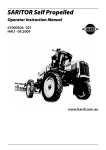
LUBRICATION POINTS
KEY
1
2
3
4
5
6
7
8
9
DAILY SERVICE
FRONT AUGER BEARING - End of Chute
HOPPER PIVOT - 1 Fitting on Right Side & 1 Fitting on Left Side
TURNTABLE PIVOT BEARING
STEERING CYLINDER REAR PIVOT - 1 Fitting on Right Side & 1 Fitting on Left Side
TURNTABLE CHAIN SPROCKETS - Left Side ( 6 Locations )
TOP FRAME PIVOT
STEERING CYLINDER FRONT PIVOT
LOWER FRAME PIVOT
TURNTABLE TRACK
KEY
10
11
12
13
13
DAILY SERVICE
T-630 Lube Points
FRONT AXLE - Hub Oil Cap ( Visual Check )
LIFT CYLINDER - LOWER - 1 Fitting Each Cylinder
LIFT CYLINDER - UPPER - 1 Fitting Each Cylinder
TOURQE HUB GREASE BOLT - 1 Fitting Each Hub
WEEKLY SERVICE
14
FRONT AXLE - 6 Locations on Brake Rods
few 2/17/06
WEEKLY SERVICE:
1. Check hydraulic oil (engine must be off)
2. Check tire pressure (65 PSI)
3. Check battery water level
-- CAUTION -Engine must be OFF, Park Brake must be ON, and Articulate
Safety Lock Bar must be LOCKED.
4. Grease front axle
MONTHLY SERVICE:
1. Check two (2) Fairfield gearboxes gear lube levels**
2. Test Engine Safety Shutdown
AFTER FIRST 50 HOURS THEN EVERY 300 HOURS OR 3
MONTHS SERVICE:
1. Change Sunstrand Suction Filter
2. Change Twin Return Filters
3. Change Gear Lube in Fairfield Hubs (80-140 w/EP additive)
YEARLY SERVICE:
1. One (1) strainer in hydraulic tank should be removed and
cleaned
2. Hydraulic oil change and flush
3. Change Gear Lube in Fairfield Hubs (80-140 w/EP additive)
** 90 - 120w Gear Lube.
5
TUCKERBILT EQUIPMENT WARRANTY
NO EXPRESS WARRANTIES AND NO IMPLIED WARRANTIES AS TO
MERCHANTABILITY OR FITNESS FOR ANY PARTICULAR USE OR PURPOSE
OR OTHERWISE (EXCEPT AS TO TITLE), OTHER THAN THOSE EXPRESSLY
SET FORTH HEREIN WHICH ARE MADE EXPRESSLY IN LIEU OF ALL OTHER
WARRANTIES, SHALL APPLY TO PRODUCTS SOLD BY TUCKER’S, AND NO
WAIVER, ALTERATION, OR MODIFICATION OF THE FOREGOING CONDITIONS
SHALL BE VALID UNLESS MADE IN WRITING AND SIGNED BY AN EXECUTIVE
OFFICER OF TUCKER’S.
Tucker’s guarantees to replace or, at its option, repair any products or parts thereof
which are found to be defective in material or workmanship within 3 months from the
date of shipment, free of charge, F.O.B. Tucker’s plant, provided that the product has
been installed in accordance with Tucker’s recommendations, and that the product
has been operated under normal conditions for the purpose for which it was
manufactured. Prompt notification of any defect and proof that the product has been
properly installed, maintained, and operated within the limits rated and normal usage
is required before Tucker’s will agree to replace or repair defective parts.
IN NO EVENT SHALL TUCKER’S BE LIABLE FOR CONSEQUENTIAL
DAMAGES, DAMAGES FOR LOSS OF USE, OR SPECIAL DAMAGES, OR FOR
TRANSPORTATION, INSTALLATION, ADJUSTMENT OR OTHER EXPENSES
WHICH MAY ARISE IN CONNECTION WITH SUCH PRODUCTS OR PARTS.
6
TUCKERBILT EQUIPMENT WARRANTY (CONT.)
If purchaser is a distributor, Tucker’s limited warranty is transferable to the initial
user, provided notice of transfer is given by purchaser to Tucker’s at the time of
such transfer, and provided further that the initial user used the products in
accordance with the requirements stated herein.
Neither the warranty nor any other provisions stated herein entitles Purchaser or
any third party to damages, direct or consequential, for Personal injury arising
from the installation, operation, or use of product furnished hereunder, and
purchaser agrees to assist Tucker’s and to hold Tucker’s harmless in
effectuation of this provision.
Machinery, parts, accessories and components manufactured by others are
warranted only to the original manufacturer’s warranty.
7
GRC TRACTOR HYDRAULIC FLUID
Bulletin No. 20581
(Supersedes No. 1022751)
DESCRIPTION: This product is a highly developed hydraulic/transmission fluid
which performs the following functions:
• Lubricates the transmission, differential and final drive gears.
• Acts as a power steering, power brake, power take-off and
implement drive fluid.
• Provides a medium with the correct friction and heat transfer
characteristics for proper operation of the tractor wet brakes and
power take-off unit.
QUALITIES:
The following characteristics make GRC Tractor Hydraulic Fluid
an outstanding product for multi-functional application:
• Superior extreme pressure (EP) and antiwear performance protects
tractor transmissions, axles and hydraulic pumps.
• The frictional characteristics are designed to minimize
“chatter” while permitting the wet brakes to hold properly. This
frictional balance also provides smooth engagement of the
power take-off clutch.
• A special blend of base helps maintain seals and gaskets used in
modern tractors.
• Its balanced formulation provides excellent rust and corrosion
protection as well as good oxidation stability for high temperature
service.
APPLICATIONS: GRC Tractor Hydraulic Fluid is recommended for most hydraulic
fluid and transmission oil applications for tractor and implements,
including:
•
•
•
•
•
•
•
•
•
Allis Chalmers PF
Allison C-3
Ford M2C134-A, M2C86-A
IH Hy-Tran
J. I. Case JIC-143, JIC-145
John Deere J-20A, J-12B
Massey-Ferguson M-1110, M-1127, M-1135
UHTF
White Oliver Type 55
8
PROPERTIES:
Gravity, API (1)
Flash Point F Min.
Viscosity, cP at 0 F Max. (2)
Viscosity, cSt at 100 C
Viscosity, SUS at 100 F (1)
Viscosity, SUS at 210 F
Viscosity Index, Min.
Pour Point, F Max.
Sulfated Ash, %
Foam Test (3)
Pounds per Gallon (1)
28.0
380
4,500
8.9-9.4
310
56-58
130
–30
1.4-1.7
Pass
7.46
Notes:
(1)
(2)
(3)
Typical value.
ASTM D 2983 (Brookfield)
ASTM 892
MOBILFLUID® 424
HIGH PERFORMANCE TRACTOR HYDRAULIC/TRANS FLUID
Approved against specifications
JOHN DEERE J20C
FORD NEW HOLLAND M2C134D
MASSEY FERGUSON M1135, M1141
ALLISON C–4 (AGRICULTURE APPLICATIONS)
VOLVO BM
WHITE NEW IDEA Q-1802, Q-1826
DENNISON HF-0, HF-1, HF-2
SAUER SUNDSTRAND
KUBOTA UDT
AGCO POWERFLUID 821XL
CATERPILLAR 10-2
CLARK
SUNDSTRAND HYDROSTATIC
ZF TE-ML06
Also recommended for service makeup and refill in
Torque converters, power-shift transmissions, final
Drives and hydraulics calling for SAE 10W-30
engine oils or mild EP fluids
9
AUGER BEARING
Rex #MBR2207
Tucker’s #80305
Shaft Size
Inches
Complete
Block No.
Size
Code
B
C
E
F
H
L
M
N
R
S
+.000
-.002
W
2-7/16
MBR-2207
8
4-19/32
3-1/2
7/8
7-5/8
5/8
2-29/32
1-13/16
1
3-1/4
5.500
3-9/16
Y
Bolt
FlangeSize
I.R. End
1-11/16
Complete Block
Net Wt. Lbs.
1/2
14.8
CENTER SWING BEARING
FAFNIR OR EQUAL
Fafnir #RCJ1-3/4
Tucker’s #80502
Fafnir flange cartridges are used in applications where a minimum amount of machining is to be done. Each unit is
furnished assembled and ready for mounting by means of bolts through the flange. They use a wide inner ring
bearing, self-aligning B type, which compensates for shaft misalignment. RCJ type flange units are equipped with
G-KRRB (R-Seal) wide inner ring bearings.
LCJ type flange units are equipped with G-KLLB (Mechani-Seal) wide inner ring bearings.
A grease fitting provides means of relubrication where required. A groove on the inside surface of the housing
conducts grease to either of two holes in the bearing outer ring.
Complete Unit & Shaft
Diameter In Inches
RCJ,LCJ,TCJ 1-3/4
A
B
C
D
E
5-3/8 4-1/8 11/16 1-5/8 2-5/16
F
G
H
J
K
RCJ
LCJ
TCJ
33/64
11/16
2-7/32
4-1/8
2-1/2
G1112KRRB
G1112KLLB
G1112KPPB2
10
Collar
No.
Housing
No.
S1112K T-16667
Approx. Unit
Wt. in Lbs.
5.70
TORRINGTON BEARING OR EQUAL
d
bore (norm.)
mm
inch
D
o.d. (norm.)
mm
Bearing designation
inch
B1
B
d1
inner ring width (norm.) outer ring width (norm.) spherical diameter (ref.)
type SF
Mm
inch
mm
inch
mm
inch
45.59
1.795
TORRINGTON #12SF20 STEERING BEARING Tucker’s #80500
31.750 1.250 50.800
2.000
12SF20
27.76
1.093
23.80
TORRINGTON #20SF32 HOPPER PIVOT BEARING
50.800 2.000 80.962 3.1875
20SF32
44.45
1.750
38.10
TORRINGTON #25SF40 ARTICULATE BEARING
63.500 2.500 100.012 3.9375
25SF40
55.55
2.187
47.62
.937
Tucker’s #80306
1.500
73.02
2.875
Tucker’s #80304
1.875
91.19
3.590
LOCK COLLAR SWING BEARING
FAFNIR OR EQUAL
FAFNIR #RCJT 1-3/4
Tucker’s #80501
Complete Unit &
Shaft Diam. in Inches
RCJT, LCJT,TCJT,
1-3/4
A
B
C
D
F
G
H
L
4-3/8 7-1/16 1-3/4 5-27/32 33/64 2-5/16 9/16 2-1/2
11
RCJT
LCJT
TCJT
Collar
No.
G1112KRRB
G1112KLLB
G1112KPPB4
S1112K
Housing Approx. Unit
No.
Wt. in Lbs.
T-21416
5.24
OPTIONAL T-630 AIR DRYER:
Bendix AD-9 Air Dryer
Bendix #065225
Tucker’s #80619
For all technical information: http://www.bendix.com/downloads/service_data_sheet/Sd082412b.pdf
Mount AD-9 Dryer vertically, outside engine compartment, in area of air flow. Provide
8 inches clearance below air dryer for servicing.
Use at least 6 ft. of discharge line between compression discharge port and air dryer
inlet for a multi-cylinder compressor and 10 ft. of line for a single cylinder compressor.
Six feet of discharge line and a 90 cubic inch reservoir can be used in lieu of 10 ft. of
discharge line for single cylinder compressors. Maximum discharge line length for all
compressors is 20 feet. The discharge line should slope downward from the
compressor to the air dryer inlet to avoid water traps and to allow drainage to the air
dryer. Discharge line material may be either high temperature hose or copper tubing.
Bendix compressors require a minimum of 4 feet of copper tubing extending from the
discharge port with the balance being either high temperature hose or copper.
12
PNEUMATIC PISTON VIBRATOR
Houston Vibrator, Inc.
All Dimensions in Inches
HVI MODEL
NUMBER
A
B
C
D
E
F
G
NPT Inlet
WT
BV-225
7-1/4
9
3-1/2
1
7-1/2
1-3/4
5/8
1/4
21
Tucker’s #80443
VIBRATOR VALVE
Parker Schrader Bellows
#015210439
Tucker’s #80442
2-way, hand-operated, large capacity, normally–closed poppet valve with rugged brass body.
Aluminum handle has large palm surface for easy actuation.
PORT
SIZE
FLOW
CAPACITY
OLD
NUMBER
MODEL
NUMBER
3/8
170 SCFM
1521W
01521-0439
ACCELERATOR VALVE
Wabco Controlair Valve
The H-1 CONTROLAIR Valve is a pedal actuated, 3way pressure regulating valve, suitable for application
where the valve portion extends below the floor level.
Depressing the pedal increases the outlet pressure.
The pedal is self-returning. This valve is suitable for
brake and clutch control or any use where foot
operation pressure control is desired.
WABCO
Tucker’s
PSI Range
0-65
0-65
Piece number
P52570-0001
80303
REPLACEMENT SEAL KIT:
WABCO #P59028
Tucker’s #80303-01
13
TWO-DIRECTION ACCELERATOR CYLINDER
WABCO ACTUATOR POSITIONER
An extremely versatile type, the Two–Direction positioner
moves ½ its total stroke length in each direction from
a center “zero” position. It is a compact, economical,
accurate linear piston type with three total stroke lengths,
1”, 1-1/2”, and 2”. WABCO’s HC-2 Controlair Valves or
MC-2 Type “M” Valves with center indexing are natural
Partners with the Two-Direction positioner.
ORDERING INFORMATION
Piece No.
Operating
Pressure
Force
Rating
Total
Stroke
Length
P59833-1000
10 - 60
820
2”
Tucker’s #80300
THROTTLE VALVE FORWARD & REVERSE
WABCO Panel-Mounted Valve
4-WAY EXHAUST CENTER VALVES
3-POSITION HANDLE
2-HA-2 PILOTAIR VALVE (with detents).
WABCO #P59335
Tucker’s #80301
PORTS SUPPLIED
HANDLE
POSITION
OUT 1
OUT 2
1
X
2
3
X
14
LIFT-SWING VALVE
Gresen #SP-4-4HP
Tucker’s #80104
Model SP Spool Directional Controller Valve
Item No.
Part No.
1
270127022703904-001
903-001
2805-001
2897-001
Description
HOUSING, SP 1-SPOOL See Note 1
HOUSING, SP 2-SPOOL See Note 1
HOUSING, SP 3-SPOOL See Note 1
2
SPOOL, 4-WAY, 3-POSITION See Note 1
SPOOL, 3-WAY, 3-POSITION See Note 1
SPOOL, 4-WAY, FREE FLOW See Note 1
SPOOL, METERING See Note 1
3
RELIEF, ADJUSTABLE, J
RELIEF, HIGH PRESSURE, ADJUSTABLE, J-HP
RELIEF, NON-ADJUSTABLE, J-NJ
RELIEF, HIGH PRESSURE, NON-ADJUSTABLE, J-NJ-HP
RELIEF, DIFFERENTIAL POPPET TYPE, NON-ADJUSTABLE, WS
RELIEF, DIFFERENTIAL POPPET TYPE, ADJUSTABLE, WSA
PLUG, NO RELIEF, NR
4
K-2028
LOAD CHECK
5
POSITIONER, SPRING RETURN TO NEUTRAL
POSITIONER, MANUAL
POSITIONER, 3-POSITION RETENT (PRIOR TO EARLY 1974)
POSITIONER, 3-POSITION RETENT (AFTER EARLY 1974)
POSITIONER, 1-POSITION WITH SPRING RETURN
POSITIONER, ROTARY RETENT
POSITIONER, SPRING EXTENDED SPOOL
LIMITER, SPOOL TRAVEL
6
7691-001
SEAL, STANDARD (2 REQ’D. FOR EACH SPOOL)
2816-001
SEAL, BUYTL QUAD RING (2 REQ’D. FOR EACH SPOOL)
2902-001
SEAL, BUNA-N QUAD RING (2 REQ’D. FOR EACH SPOOL)
7
902-001
HANDLE ASSEMBLY, SHORT
2580-001
HANDLE ASSEMBLY, STANDARD
3461-001
HANDLE ASSEMBLY, OFFSET TO RIGHT
3462-001
HANDLE ASSEMBLY, OFFSET TO LEFT
8
PLUG, CLOSED CENTER
PLUG, CONVERSION
SLEEVE, POWER BEYOND
NOTE 1: These are matched parts and are not sold separately. A complete valve assembly must be ordered.
Refer to Monoblock product catalog No. 10401 for complete details and ordering instructions.
15
CYLINDER LOCK
Vicker’s #02-160853
Tucker’s #80215
HOT OIL SHUTTLE VALVE
Sunstrand #8800485-2400
Tucker’s #80202-01
16
SPEED SELECTOR – TRANSMISSION
WATERMAN HYDRAULICS
Waterman #12C51SM-A12T6
Tucker’s #80202
17
MODEL CFD FLOW DIVIDER
GRESEN #CFD50-5-HP
Tucker’s #80109
Parts List
ITEM
1
2
3
4
5
6
7
8
9
10
11
12
13
14
15
16
17
18
19
20
PART NO.
015-001
2707-001
1458-001
14601447-001
1462-001
1463-001
1464-001
1465-001
1466-001
1467-001
1468-001
1469-001
1470-001
1456-001
1455-001
1459-001
1448-001
1449-001
1450-001
1451-001
1452-001
2504-001
2503-001
1453-001
1454-001
458-001
459-001
462-001
1458-001
2707-001
073-001
DESCRIPTION
Plug
O-ring seal
Spool cap, Solid
Housing
Spool – see options below
1.5 GPM
2.0 GPM
3.0 GPM
4.0 GPM
5.0 GPM Controlled
6.0 GPM flow Gallonage
7.0 GPM
8.0 GPM
9.0 GPM
10.0 GPM
Spool Spring
Spool Spring Guide
Spool Cap, Hollow
Spool Spring Shim
Relief Cap
Relief Spring (0-1500)
Relief Spring (1501-2500PSI)
Spring Guide
Relief Ball
O-ring seal
Backup Washer
Relief Seat
Shim (.040 thick)
Shim (.020 thick)
Shim (.010 thick)
OPTIONAL NR RELIEF
NO. REQ.
1
3
1
1
1
Spool cap (Solid)
O-ring Seal
3/8” NPT Pipe Plug
1
1
1
PORTING KEY
CF = Controlled Flow
EF = Excess Flow
P = Pressurized Oil From
Pump
T
1
1
1
1
1
1
1
1
1
1
1
As reqd.
As reqd.
As reqd.
18
= Relief Valve Return to
Tank (from constant
flow side only)
Note: This port
plugged on (NR)
models.
DIFFERENTIAL-POPPET RELIEF VALVE
Model WJ & WJL Series
Gresen #WJL-75
Tucker’s #80211
Set @ 2,000 PSI
INSTRUCTIONS FOR ADJUSTING THE RELIEF SETTING
Remove 1881-001 cap and add shims to increase setting or remove shims to
decrease setting. Shims must be placed over stem of 1881-001 relief poppet under
spring.
CAUTION: Never attempt to adjust relief pressure without use of a reliable gage in the system.
Parts List
Item No. Part No.
K-19002
K-6006
1
458-001
2
459-001
3
462-001
4
1450-001
1864-001
1451-001
1865-001
5
1615-001
6
1718-001
7
2707-001
8
1880-001
1880-003
9
1881-001
10
1883-001
11
1890-001
1890-002
12
2716-004
2716-005
13
2818-008
2818-006
14
1234-001
Description
Service kit (Contains Items 10 and 11)
SEAL KIT (Contains Items 5, 6, and 7)
SHIMS (.040)
SHIMS (.020)
SHIMS (.010)
SPRING, Relief Pressure (Choose one)
500-1350 PSI, No Color
1351-1750 PSI, Silver
1751-2200 PSI, Yellow
2201-3000 PSI, Red
SEAL, O-Ring Order K-6006
SEAL, O-Ring Order K-6006
SEAL, O-Ring, Order K-6006
CAP, Relief, without hole lockwire (Standard)
CAP, Relief, with hole for lockwire (Optional)
POPPET, Relief Order K-19002
RING, PISTON Order K-19002
BODY, Relief, without hole for lockwire (Standard)
BODY, Relief, with hole for lockwire (Optional)
Housing, SAE 10 Ports
Housing, ½” NPTF Ports
Housing, SAE 10 ports
Housing, ½” NPTF Ports
LOCKWIRE and LEAD SEAL (Not shown)
19
Quantity
A/R
A/R
A/R
1
1
1
1
1
1
1
1
1
1
1
1
1
1
A/R
A/R
A/R
A/R
1
AUGER SELECTOR VALVE
Gresen Model S75
Tucker’s #80111
Parts List
ITEM
No. Req’d
S-50
Part No.
Description
S-75
Part No.
S-100
Part No.
1
1
Valve Housing
*1140-001
*1120-001
*1310-001
2
1
Valve Spool
*1139-001
*1130-001
*1311-001
3
2
Snap Ring
602-001
1127-001
1312-001
4
2
Spool Seal
8021-001
7700-001
8020-001
5
1
Control Knob
081-001
081-001
081-001
6
1
Lock Washer
1291-001
1291-001
1291-001
7
Opt.
Handle Adapter
1478-001
1478-001
1478-001
8
Opt.
Cotter Pin
086-001
086-001
086-001
9
Opt.
Handle Pin
085-001
085-001
085-001
10
Opt.
Lock Washer
603-001
603-001
603-001
Available Kits-Seal Kit contains items 3 and 4
K-13001
K-14001
K-15001
Control Knob Kit contains items 5 and 6
K-13002
K-13002
K-13002
Clevis Adapter contains items 7 and 10
K-13003
K-13003
K-13003
*Not sold as separate items. Spools are factory honed to individual housing and are not
interchangeable. Repair service available at factory.
20
INSTRUCTIONS FOR REPLACING SEALS
ON MODEL S75 SELECTOR VALVE
IMPORTANT: When installing new seals care must be taken to
prevent dirt entering valve or system. Extreme
care must also be taken to avoid cutting new
seals when installing in valve.
1. Remove Snap Rings at handle end and rear end of spool.
2. Push knob in until rear Seal is exposed. Remove rear Seal.
3. Spool may now be removed from valve body. Remove front Seal from
spool.
4. To prevent cutting Seal on sharp edges, wrap spool in 3 or 4
layers of glossy paper, leaving only the front Seal groove
exposed. Install new Seal from rear of spool over the paper
and into the Seal groove.
5. Apply clean grease to new Seal. Remove paper and insert
spool in body and with a rotating action on knob, push in
spool until front Seal disappears and until rear Seal groove
is exposed.
6. Install rear Seal in grove.
7. Apply clean grease to rear Seal.
8. IMPORTANT – Now install rear Snap Ring and with firm
rotating action pull Spool to stop.
9. Install front Snap Ring.
21
VIBRATOR OILER VALVE
VERSA VALVES
SERIES “B”
Normally Closed
Palm Button
For Panel Mtg.
Two-Way
BLK-2208-P25B
Tucker’s #80106
THROTTLE CYLINDER
CYLINDERS AND VALVES, INC.
22
AUGER MOTOR
CHAR-LYNN #119-1030
Tucker’s #80102
EACH ORDER MUST
INCLUDE THE
FOLLOWING:
1. Product Number
2. Data Code
3. Part Name
4. Part Number
5. Quantity Parts
Type of motor Type of shaft
Standard
Straight
Ports
1-5/16 O-ring
Displacement Cu. In./rev. and Product Number
20.6
29.2
40.6
57.4
119-1030
23
SWING MOTOR
CHAR-LYNN #104-1035
Tucker’s #80103
Type of Motor
Type of Shaft
Ports
Displacement (cu. In./rev.) &
Product Number
EACH ORDER MUST
INCLUDE THE
FOLLOWING:
1. Product Number
2. Data Code
3. Part Name
4. Part Number
5. Quantity Parts
24
Standard w/2 Bolt SAE A Flange
1-1/4 14 T Splined
7/8–14 O-ring
18.7
T-630 TANK RETURN FILTER
GRESEN #FLR415-5EDNH
Tucker’s #80101
INSTALLATION INSTRUCTIONS
1.
2.
3.
4.
When mounting filter on equipment, allow
1” clearance below filter for easy
replacement of dirty filter element. For
convenience and best results, mount filter
in vertical position with Filter Housing
“DOWN”.
Be sure to connect filter for oil flow in
direction of arrows cast on Filter Head.
If possible, plumb filter into system so that
when the Filter Housing is removed to
clean or replace element, oil supply in
reservoir will not drain. This can be
accomplished by making certain that the
lower surface of the Filter Head Casting is
above Reservoir Oil Level.
To change from “Suction-Line” Filtration
(line Between Reservoir Tank and Pump
Intake) to “Return Line” Filtration (line
between Outlet of Control Valve to
Reservoir Tank) or vice-versa, see
INSTRUCTIONS TO REPLACE BY-PASS
SPRING.
DESCRIPTION
K-23013
NO. REQ’D PER ASSEMBLY
FILTER ELEMENT
3293-001Element, 10 micron paper
2
COMPLETE SEAL AND ELEMENT KIT
K-23015 3276-001 Element,10 micron shielded
2
Elements and Seal Kits contain one each of items 2, 8, 7, and two of item 6.
ITEM 2 Flat Gasket 1575-001
ITEM 8 “O” Ring 1576-001
25
FS250 SERIES
HYDRAULIC SYSTEM FILTER
GRESEN #SP212-1EDNH
Tucker’s #80107
INSTALLATION INSTRUCTIONS
1.
When mounting Filter, allow 1-1/2” clearance below
filter for easy replacement of dirty Filter Element.
For convenience and best results, mount Filter in
vertical position with Filter Housing “DOWN”.
2.
Connect Filter for oil to flow in direction of arrow
cast on Filter Head.
3.
If possible, install Filter so that when the Filter
Housing is removed to replace element, oil supply
in Reservoir will not drain. This can be
accomplished by making certain that the lower
surface of the Filter Head Casting is above
Reservoir Oil Level.
4.
To change from “Suction-Line” Filtration (line
between Reservoir Tank and Pump-Intake) to
“Return Line” Filtration (line between Control Valve
Outlet and Reservoir Tank) or vice-versa.
5.
Follow instructions printed on Filter Element can
when changing Elements.
PARTS LIST
1
2
3
4
PART
NUMBER
See Table 1
7519-001
7507-XXX
7510-001
5
K23028
6
6673-001
7
8
0015-001
See Table 2
ITEM
DESCRIPTION
Filter Element
Filter Element Seal
Head Casting, FS250*
Relief Valve Poppet
No. 6671-001 Compound
Indicator With No. 6673001 Decal and No.6672001 30” Vacuum Indicator
Indicator Decal, Red, For
Compound Indicators only
1/8” Pipe Plug, optional
Relief Valve Spring
QUANTITY
REQ’D
1
1
1
1
1
1
1
1
* Filter Head Casting is not available as a spare part. Order complete Filter
26
TABLE 1 – FILTER ELEMENT
DESCRIPTION
PART NUMBER (STAMPED
ON ELEMENT)
7531-001
7520-001
7521-001
KIT NUMBER * (FOR COMPLETE
KIT REPLACEMENT)
K-23020
K-23018
K-23019
3 Micrometer, Paper
10 Micrometer, Paper
25 Micrometer, Paper
* Complete Kit includes 1 Element (Item 1) and 1 Seal (Item 2) shown in the Parts List.
Note: Element Kits are packed 12 Elements per case.
TABLE 2 – RELIEF VALVE ASSEMBLY
PRESSURE
RATING
APPLICATION
SPRING
COLOR
PART
NUMBER
3 psi
5 psi
9 psi
15 psi
25 psi
Suction Line
Suction Line
Suction Line
Return Line
Return Line
Blue
Black
Red
Silver
Steel Gray
7511-001
7512-001
7513-001
7514-001
7515-001
KIT NUMBER*
(For Complete
Kit Replacement)
K-23023
K-23021
K-23024
K-23022
K-23025
* Complete Kit includes 1 each of Item 4 and 8 shown in Parts List
INSTRUCTIONS TO REPLACE RELIEF VALVE SPRING
TOOLS REQUIRED
1.
2.
Hold Relief Poppet in place with a ½” Allen wrench.
Depress Spring, turn counterclockwise. To simplify
Spring removal, make a simple Spring Replacement
Tool by using electric conduit or tubing as follows:
a.
Cut a section of 1-1/8” O.D., 1” I. D. by 4” long
electric conduit or equal.
b.
Cut 2 notches 1/8” wide by 1/8” deep. Place Tool
notches over Spring, depress and turn
counterclockwise
3.
Remove Spring and Poppet.
4.
Install new Spring.
Note: The 5 PSI Spring is standard for suction line
applications. 3 PSI and 9 PSI Springs are
optional. The 15 PSI Spring is standard for
return line applications. 25 PSI Spring is
optional.
Caution: When replacing poppet and spring make
sure that poppet is always installed from
the outlet side of the filter head and the
spring from the inlet side.
27
CONDITION INDICATOR INSTALLATION INSTRUCTIONS
If filter is installed in “Return-line” (Line from Outlet of Control Valve to reservoir Tank), the indicator
must be installed on the “pressure” side of the filter designated by the word “IN” cast in the Filter Head.
For “Suction Line” operation (Line between Reservoir Tank & Pump Intake), install the indicator on the
“suction” side, designated by the word “OUT” cast in the Filter Head.
INSTRUCTIONS FOR PROPER MARKING OF “DANGER ZONE” ON INDICATOR DIAL FACE.
1. If unit is operated as a “Suction-Line” Filter, indicator dial has danger zone marked on dial starting
at 10” Hg(5 PSI Spring) and the Red Decal is not required. To avoid possible damage to your
pump, check with the manufacturer to determine the max. safe inlet drop allowed.
EXAMPLE: When Filter is installed in “Suction Line” ahead of pump, some allowable restriction is
created. As dirt or foreign matter is collected in Filter, increase suction is required.
This may cause starvation or cavitation of pump prior to the opening of Filter Relief
Valve, which is normally set at 10” Hg(5 PSI Spring). Gresen Vane Pumps are
designed to withstand a suction of 10” Hg(5 PSI Spring).
2. If unit is operated as a “Return Line” Filter, (with 15 PSI Spring) take pressure reading on Filter
Condition Indicator when Filter is clean and with oil at operating temperature. Disregard Indicator
reading until oil reached operating temperature. To this figure, add the number from the chart
below, which corresponds to your particular installation. The total of these two figures represents
the point on the lndicator dial face at which the enclosed Red Decal should be placed when the 15
PSI Spring is installed. This will be the starting point of DANGER ZONE. The Relief Valve begins
to open as the needle enters into the RED DANGER ZONE. This indicates that the Filter Element
should be changed or cleaned to avoid the possibility of circulating any dirty oil through the
system.
3. When installation has been completed, and before starting oil flow in the system, check Indicator
to be sure needle is on “0”.
PUMP
OUTLET
(GPM)
0 - 20
21 - 30
31 - 40
41 - 50
51 - 60
RETURN-LINE INDICATOR CALIBRATION CHART
(150 SUS OIL and FILTER ELEMENT)
MODEL FS250 FILTER
PAPER ELEMENT PAPER ELEMENT PAPER ELEMENT
3 MICROMETER
10 MICROMETER
25 MICROMETER
10
6
2
-
13
11
9
5
-
28
14
12
9
7
5
HYDRAULIC OIL LEVEL SENSOR
APPROVED PURIFICATION CORP.
Approved Purification Corp. #L2500
Tucker’s #80213
IN-TANK STRAINER
HYDRAULIC SUPPLY COMPANY
Hydraulic Supply Co. #SU65SF32
Tucker’s #80100
ORDERING INFORMATION
TYPE OF ELEMENT ELEMENT AREA
S
U
Cm2
In2
6
One Pc.
U
2903
450
6
NORMAL MICRON
THREAD STANDARD LINE
MAGNET
RETENTION
(N.P.T.)
SIZE (in inches)
5
S
F
32
150
No
5
S Female F
2
32
(100 mesh)
Magnet
29
HEAT EXCHANGER (OIL COOLER)
Thermal Dynamics #DHR2491130
Tucker’s #80207-1
RUBBER MOUNTS FOR HEAT
EXCHANGER
Thermal Dynamics #L84740
Tucker’s #80207-02
BENDIX D-2 GOVERNOR
Bendix #BW275491
Tucker’s #80609
AIR COMPRESSOR
Bendix #108261
Tucker’s #80609-01
12 CFM at 1250 RPM
Available Remanufactured Exchange
Maintenance Kit with High Temperature ORings PC. No. 280915
Maintenance Kit with Standard O-Rings
276121
30
Bendix Air Valves
31
AIR HORN
Tucker’s #80608 Air Horn Kit (includes
valve, horn, tubing, & fittings
Grover Products
Grover #1601Dual Connected Truktone Horn
Tucker’s #80608-2 Air Horn
Bendix Horn Valve Model HV-3
Tucker’s #80608-1 Horn Valve
AIR BRAKE AIR RESERVOIR
Tucker’s #80610
AIR PRESSURE GAUGE
Bendix #225635
Tucker’s #80607
32
REYCO INDUSTRIES INC.
P. O. BOX 2268 - SPRINGFIELD, MO. 65801-2268
TELEPHONE 417 – 862-4343 - TELEX: 436424 REYCO SPG. - FAX 417 – 862-0343
102 TRACTOR SUSPENSION
MAINTENANCE RECOMMENDATIONS
The 102 Tractor Suspension, by design, requires a minimal amount of Maintenance.
However, suspensions in over–the–road operations require periodic checks to assure
continued trouble free performance.
Our recommended 180 day inspection procedure is to :
1.
Check ¾” u-bolt nuts to assure maintenance of 300 ft. lbs. torque.
2.
Check all hanger mounting bolts to assure tight fit of hanger to frame. For specific
torque recommendations, consult the vehicle service manual or manufacturer.
3.
Check equalizer nut (equalizer bolt) to assure that 600 ft. lbs. torque is maintained.
4.
Check torque arm bolts to assure that 160-200 ft. lbs. Torque is maintained.
5.
Check ¾” torque arm clamp nuts to assure that 125-150 ft. lbs. torque is maintained.
Insure the clamp is directed away from the spring to prevent possible interference
during operation.
6.
Check fit of springs to hangers and equalizer to assure continued good “ride”
characteristics of Reyco suspension.
We recommend, during pre-delivery and after the first 1,000 miles of operation, that all of the
above items be checked, including a check of the suspension alignment.
In addition to checking alignment during pre-delivery and at the first 1,000 miles of operation,
suspension alignment should be checked when any one of the following conditions prevail:
1.
Discovery of a loose suspension fastener. (Loose is defined as any torque below the
recommended torque).
2.
Discovery of elongated holes in a suspension component.
3.
When bushings are being replaced.
4.
Excessive or abnormal tire wear.
To insure an accurate torque reading, the torque tool used for checking torque must provide
a correct measurement. Also, the nut and bolt should be dry (free of any lubrication) and
clean (free of any dirt, grit, rust, etc.).
36
T-630 Hose Contents
Part #
Qty
Hose Placement
81929
1
Left Wheel Motor (rear port) to Right Side Top
Port Sunstrand Pump
81930
1
(65 ½”) Left Wheel Motor (front port) to Left
Port Sunstrand Pump bottom Tee – Center
Port
81931
1
Vickers Pressure Right Side Outside Adapter
Line to Auger Valve
81932
2
Auger Valve to Auger Motor (Lines to Cross)
81933
1
Auger Valve Return Line
81934
1
Air Compressor to Air Tank
81935
1
Lower Articulate Pin Grease Line
81936
1
Return Line for Fuel
81937
1
Grease Line (Auger Bearing)
81938
2
(Under Rear Frame Assembly) 2 Grease Lines
(Steering Cylinder)
81939
1
Upper Articulate Pin Grease Line
81940
81941
1
1
Sunstrand Pump to Suction Filter
Gate Valve to Vickers Pump
81947
1
Upper Turntable Grease Line: Rear Nylatron
43
Contents
Qty
Part #
1
BA12FR12
1
BA12FRC12
31”
FC136-12
2
1BA12FR12
66.5”
FC136-12
2
219”
2
93.5”
2
2
189”
1AA16FR16
GH781-16
1AA16FR16
GH781-16
1212-20S
FJ8706-2020S
FC300-20
2
1206-10S
2
2
116”
1
1
18”
1
1
187”
1
1
12”
1
1
10
1
1
15”
34”
10”
1
1
10.5
63-473A-10
900568-10B
2807-10
1AA4MP4
1AA4FJ4
GH781-4
1AA4MFA4
1AA5FJ4
GH781-4
1AA2MP4
1AA4FJ4
GH781-4
1AA2MP4
1AA4FJ4
GH781-4
1AA4MP4
1AA4FJ4
GH781-4
2661-20
2661-32
1AA4FJ4
1AA4MP4
GH781-4
T-630 Hose Contents
Part #
Qty
Hose Placement
81948
1
Upper Turntable Grease Line: Front Nylatron
81949
1
Upper Turntable Grease Line: Center Bearing
81950
2
Cushion Valve to Swing Motor (Top to Top &
Bottom to Bottom)
81951
1
Auger Valve Outlet Tee Straight End to Auger
Speed Selector
81952
1
Two Speed Selector to Pump
81953
1
Two Speed Selector Return
81954
2
1 – Two-Speed Selector to Left Wheel Motor
Bottom
1 – Left Motor Bottom to Right Bottom
81955
2
1 - Two Speed Selector to Left Wheel Motor
Top
1 – Left Motor Top to Right Top
81957
1
Hot Oil Valve to Oil Cooler
81958
1
Bottom of Pump Tee Blocks to Hot Oil Valve
81959
1
Bottom of Pump Tee Blocks to Hot Oil Valve
81960
2
Torque Hub Grease Line
81961
1
Top Swing Bearing Grease Line
81962
1
Bottom Swing Bearing Grease Line
44
Qty
1
1
22.5
1
1
11.5”
1
1
Contents
Part #
1AA4FJ4
1AA4MP4
GH781-4
1AA2MP4
1AA4FJ4
GH781-4
1AA8FR8
1AA8MP8
34.5”
GH781-8
1
1
31”
2
30”
1
54”
1
1
64”
1AA12FR12
1AA12FRB12
GH781-12
1AA6FR6
GH781-6
1AA8FR6
GH781-6
1AA6FR6
1AA6FRB6
GH781-6
2
1AA6FR6
62.5
GH781-6
1
1
23”
2
90”
2
72”
4
72”
1
1
12”
1
1
6.75”
1AA8FR8
1AA8FRB8
GH781-8
1AA8FR8
GH781-8
1AA8FR8
GH781-8
1AA4FJ4
GH781-8
1AA4MFA4
1AA4FJ4
GH781-4
1AA4MFB4
1AA4FJ4
GH781-4
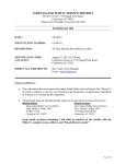
Auburn
Power Wheel Hub
To Disengage Gearbox for Towing
Remove (2) ¼” Bolts holding Disengage Cap.
Turn cap over and bolt back on the housing.
Reverse the procedure to re-connect the gearbox for driving. Caution must be taken to make certain the
Disengage rod is in the out position before re-installing the cap!!!!
Procedure must be done to both gearboxes
Power Wheel® Service Manual
Model 10 Double Reduction
Wheel Drives
AUBURN, INDIANA 46706-3499
U.S.A.
PHONE: (219) 925-3200
FAX: (219) 925-4725
4
1
2
3
5
6
7
8
10
9
11
12
17
13
16
➛
15
14
19
22
18
27
23
24
28
25
29
26
33
34
35
20
21
32
30
31
OPTIONAL
IDENTIFICATION
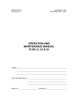
IMPORTANT: All Power Wheel units and kits are shipped with a nameplate that includes the Auburn Gear part number and order code as shown.
Power Wheel®
Example:
ORDER CODE: 6WB13156C
PART NO.: 6000236
SERIAL NO.: 143434
AUBURN, IN U.S.A.
In addition to the nameplate, Power Wheel drives are stamped with an identification number which appears on the cover or hub flange as shown.
Example:
6000236-A-4-9
When ordering parts, the information included on the nameplate or the stamped identification number is necessary to accurately identify the drive
and obtain the correct replacement parts. Once this information has been obtained, contact Auburn Gear for the appropriate parts list.
DISASSEMBLY OF POWER WHEEL
STEP 1
STEP 8
Slide the coupling (2) from splines on input shaft (3).
Remove the bearing nut lock screw (21).
STEP 2
STEP 9
Position the assembly upright on face of spindle (4).
Remove the secondary carrier assembly (19). Removal is accomplished by
loosening the lock screw (21) and bearing locknut (20) until the carrier assembly
can be removed from spindle (4) splines. Loosen lock screw (21) with 3/16 hex
drive. It may be necessary to remove the ring gear (17) first, if difficulty is encountered in removing the carrier. NOTE: A special service tool is required for
removal of the bearing locknut. Contact Auburn Gear for procurement of service
tool, part number 592Y.
STEP 3
Remove the disengage cover (31) if necessary.
STEP 4
Remove twelve bolts (29), flat washers (28) and large cover (27). Disengage
plunger (25) usually remains with large cover (27). Remove plunger (25) and “O”
ring (26) from cover or end of input shaft (3). The thrust washer (24) will usually
remain in position on the thrust face of large cover (27).
STEP 10
STEP 5
Remove the ring gear (17). It may be necessary to strike ring gear (17) with a
rubber mallet to loosen from hub.
Remove primary sun gear (23) from end of input shaft (3).
STEP 11
STEP 6
Remove thrust plate (13) from in front of the tapered bearings and lift hub (10)
from spindle (4). If bearings are not a loose fit, it may be necessary to press
spindle from hub.
Remove the primary carrier assembly (22).
STEP 7
STEP 12
Remove the input shaft (3) from the assembly. The disengage spring (15), thrust
washers (14), and retaining rings (16) will remain intact on the input shaft. Remove these components only if replacement is required.
Remove the oil seal (6) and bearing cones (7 & 12) from hub (10). Inspect
bearing cups (8 & 11) in position and remove only if replacement is required.
ASSEMBLY OF POWER WHEEL
STEP 1
STEP 7
Press new bearing cups (8 & 11) in each side of the hub (10). It is recommended
that bearing cups (8 & 11) and cones (7 & 12) be replaced in sets.
Assemble a washer (14), spring (15), a second washer (14), and a retaining ring
(16) in the middle groove of input shaft (3). Install a second retaining ring (16) in
groove near small end of input shaft (3).
STEP 2
STEP 8
Assemble bearing cone (7) into cup (8) at seal end of hub (10) and press a new
seal (6) into hub (10). Install boot seal (5) on hub (10) if unit is so equipped.
Place the input shaft (3) down into spindle (4) with the snap ring end of the shaft
up.
STEP 3
STEP 9
Position spindle (4) upright on bench. Lubricate lips of seal (6) and lower hub
(10) onto spindle (4). Hub (10) should be centered as it is lowered over spindle
(4) to prevent seal damage.
Assemble bearing cone (12) over spindle (4) and into bearing cup (11). Replace
thrust plate (13) over spindle end splines and on bearing cone (12).
Assemble the primary carrier assembly (22) into the ring gear (17). It will be
necessary to rotate carrier to align secondary sun gear {part of primary carrier
assembly (22)} with planet gear teeth in secondary carrier assembly (19). Assemble primary sun gear (23) over input shaft (3). Rotate primary sun gear (23)
to align input shaft (3) to gear splines and gear teeth in primary carrier assembly
(22).
STEP 5
STEP 10
Assemble secondary carrier assembly (19) splines over splined end of spindle
(4). Install bearing locknut (20). Tighten locknut to 75 lb. ft. (101.9 Nm) while
rotating the hub to seat bearings. Loosen the locknut 1/2 turn then retighten
locknut to 85 – 90 lb ft. (115.2 – 121.9 Nm) while rotating the hub. Loosen the
locknut to nearest locking notch and secure with lock screw (21). Tighten lock
screw to 20 – 25 lb. ft. (27.2 – 34.0 Nm).
Lubricate “O” ring (26) and assemble in groove inside cover hole, push plunger
(25) into cover with pointed end facing inside of unit.
STEP 4
STEP 11
Assemble the thrust washer (24) with tangs engaged with cover (27). NOTE: A
small amount of grease applied to the back side of thrust washer (24) will hold
washer in place. Apply a bead of silicone sealant to end face of ring gear (17).
Assemble cover (27) aligning holes of cover and ring gear. Install the twelve
Grade 8 bolts (29) and flat washers (28) which retain cover (27) and ring gear
(17) to hub (10). Torque bolts to 120 – 130 lb. ft. (163.2 – 176.8 Nm).
STEP 6
Clean mating surfaces and apply a bead of silicone sealant to face of hub (10)
that mates with ring gear (17). (See instructions on sealant package) Assemble
ring gear (17) to hub (10) being careful to align all bolt holes.
2
STEP 12
STEP 14
Assemble the disengage cover (31) with dimpled center protruding out if wheel
is to be used to drive the vehicle. Assemble and torque the two 5/16 - 18 x 1/2
inch bolts (32). Torque bolts to 10 - 20 lb. ft. (13 - 27 Nm).
After motor is assembled to drive or drive is sealed at spindle, fill with lubricant
to proper level and replace all plugs.
STEP 13
NOTE: When installing a hydraulic motor to the Power Wheel drive it is
necessary to place an “O” ring or gasket (not supplied by Auburn Gear)
between the motor and the planetary drive. “O” ring sizes: SAE A 2-042, SAE
B 2-155, SAE C 2-159.
If required, assemble a new retaining ring (1) into groove in inside diameter of
coupling (2). Invert the Power Wheel assembly and assemble the coupling (2),
with end nearest retaining ring out onto the input shaft (3). NOTE: Coupling (2)
must be assembled to input shaft so that end with retaining ring is nearest motor
or spindle side of drive.
CARRIER ASSEMBLIES
It is recommended that the secondary and primary carrier assemblies (19 & 22) be serviced in their entirety to protect the integrity of the Power Wheel drive.
LUBRICATION RECOMMENDATIONS
IMPORTANT: POWER WHEEL PLANETARY DRIVES ARE SHIPPED WITHOUT LUBRICANT AND MUST BE FILLED TO THE PROPER LEVEL PRIOR
TO START UP.
Observe lubrication recommendations given by the original equipment manufacturer. When specific recommendations are not available, use mild extreme
pressure lubricant API-GL-5, No. 80 or 90 when filling the Power Wheel under normal temperature ranges between 0 - 120°F (-18 to 49°C). Power Wheel is to
be half full of oil when unit is mounted level and horizontal. Use drain and fill plugs located in cover and ring gear. Oil is to be changed after first 50 hours of
operation with subsequent changes every 1000 hours or yearly, which ever comes first. If unit is to be operated vertically, if ambient conditions are outside the
specified range, or if the oil temperature exceeds 200°F (93°C) contact Auburn Gear for oil and level recommendations.
TOWING VEHICLE
CAUTION: The Power Wheel will not normally be damaged by towing; however, the hydraulic drive components may be damaged unless the Power Wheel is
disengaged from the drive motor. Road speeds in excess of 25 MPH should be avoided unless clearly specified to be permissible by the equipment manufacturer.
TO DISENGAGE POWER WHEEL
CAUTION: For units equipped with the standard spring disconnect, assemble the disengage cover (31) with the dimpled center protruding inward. For units
equipped with the optional quick disconnect, push in center plunger of disconnect. PARKING BRAKE WILL NOT FUNCTION IF UNIT IS DISENGAGED.
STORAGE
A protective film is applied to the Power Wheel at the factory to prevent rust during shipment. Additional protection may be required if the Power Wheel is to be
stored for an extended period of time.
SEALING COMPOUND
Silastic RTV732 sealer and General Electric Silimate RTV No. 1473 or RTV No. 1503 are currently recommended for sealing gasket surfaces. Sealant should
be applied in a continuous bead, which should be centered on the surface to be sealed but should move to the inside of the hole at each bolt hole location. For
service requirements order Auburn Gear part number 604101.
SPECIFICATIONS
Maximum intermittent output torque ............................................................................................................................................. 180,000 lb. in. (20,340 Nm)
Maximum input speed ....................................................................................................................................................................................... 5,000 RPM
Oil capacity .............................................................................................................................................................................................. 150 oz (4,435 ml)
3
ITEM
NO.
DESCRIPTION*
NO. USED
IN ASS’Y.
ITEM
NO.
DESCRIPTION*
NO. USED
IN ASS’Y.
1
Retaining Ring
1
19
Secondary Carrier Assembly
1
2
Coupling
1
20
Locknut
1
(Serviced as part of the Carrier Assembly)
3
Input Shaft
1
21
Lock Screw 618304
1
(Serviced as part of the Carrier Assembly)
4
Spindle
1
22
Primary Carrier Assembly
1
5
Boot Seal 604411
1
23
Primary Sun Gear
1
6
Oil Seal 604404
1
24
Thrust Washer
1
7
Bearing Cone 613305
1
25
Disengage Plunger
1
8
Bearing Cup 613306
1
26
“O” Ring 614101
1
9
Wheel Bolt
12
27
Large Cover
1
10
Hub
1
28
Flat Washer 604703
12
11
Bearing Cup 613313
1
29
Hex Head Bolt (Grade 8)
12
12
Bearing Cone 613312
1
30
Pipe Plug 03-04-101-09
1
13
Thrust Plate 619304
1
31
Disengage Cover 14-02-039-005
1
14
Washer
2
32
Hex Head Bolt 618305
2
15
Disengage Spring 615603
1
33
Quick Disconnect Gasket
1
16
Retaining Ring
2
34
Quick Disconnect Assembly
1
17
Ring Gear
1
35
Hex Head Bolt
2
18
Magnetic Plug 14-00-052-002
1
* Contact Auburn Gear with part number and order code of drive to obtain the appropriate parts list.
Refer to parts list for the specific part numbers and quantities.
Model 10 Power Wheel® Service Kits
Part No.
Description
Included Items
592Y
Model 10 Bearing Locknut Tool
Not Shown
MH441 - 0497
Power Wheel® is a registered trademark of Auburn Gear
Bill of Materials for Part Number: 60001861 (Order Code: 0W2B13519ZR ~ 10" P.W. - 1ST A)
there is no service manual available for this part number
Need
Pack
6079146
Part
SPINDLE ~ #10 - INT B/N - 1ST
Description
1
1
604411
SEAL-BOOT ~ #10
1
1
604404
SEAL-OIL, MODEL 10
1
1
608938
COUPLING ~ #10 - 1ST ARTICLE R
1
1
613305
BEARING-CONE
1
1
613306
BEARING-CUP
1
1
613312
BEARING-CONE
1
1
613313
BEARING-CUP
1
1
617930
HUB ~ 10"
1
1
619304
WASHER-THRUST
1
1
604702
WASHER-SPR BACK UP
2
1
615603
SPRING-DISENGAGE
1
1
618914
SHAFT-INPUT ~ #10
1
1
613914
RING-RETAINING
2
1
10-00-041-002
COMPOUND-SEALING - 10.3 OZ. CA
1
1
603924
COVER ~ 10" WD
1
1
614101
RING-O (SVC = 10/PKG)
1
10
14-02-039-005
COVER-DISENGAGE ~ 6"
1
1
618305
BOLT-HEX HEAD ~ 5/16-18 X. 5
2
1
610801
PLUNGER
1
1
604703
WASHER-FLAT
12
1
0009430269
BOLT-HEX HEAD ~ 9/16 X 12 X 6"
12
1
14-00-191-003
PLUG-SHIPPING, SAE B, 4.06" O.
1
1
14-00-052-002
PLUG-PIPE ~ 1/2-14 MAGNET (SV
1
2
03-04-101-09
PLUG-PIPE ~ 1/8-27
1
1
616217
GEAR-RING ~ 10"
1
1
616564
GEAR-PRI SUN ~ #10
1
1
665963
ASSY-PRI CARRIER ~ 10"
1
1
665964
ASSY-SEC CARRIER ~ 10"
1
1
14-00-193-003
WASHER-THRUST (SVC = 5/PKG)
1
5
618310
BOLT-WHEEL ~ 3/4-16 NF2A (SVC
12
10
T-630 Chute Kit Assembly and Installation
81990
81990-12
21ft Chute Kit
22ft Chute Kit
A piece of beam or channel works well to keep chute
pieces aligned. Aligning center bend lines on bottom,
work from center around to weld the three sections
together as shown, inside and out. Grind outside flat
where it will slip up into chute channels.
Cut spacer rods from scrap rebar or similar about 14-1/4” long.
Squeeze chute to spacers and tack weld. Shown below.
The chute is ready to install.
Remove Auger and old Chute from T-630. Clean concrete build up from all surfaces where
new components will mate.
Caulk one Chute Bolt Flange and install to
rear of hopper.
Install Chute into position, resting on Chute Bolt Flange just installed
making sure bolt holes are aligned.
Start about the middle of the Chute installing bolts on each side, but do not tighten. Work
toward the discharge end of the chute installing the rest of bolts, still not tightening. Install the
Bearing Cap and Chute Bolt Flange, leaving them loose also.
Next steps critical to maintain chute alignment.
Level the Chute Channels to the level of T-630. Use weights or crane to
maintain level.
Loosely install bolts from middle of chute toward hopper as far as easily
reached from outside hopper. Caulk each side of Chute from hopper to
just in front of cab.
From inside hopper, caulk each side of the Chute.
Loosely install all remaining bolts. Then tighten all bolts in the hopper
area. Break out temporary spacers as you go.
Now back outside the hopper, caulk about 1/3 of remaining chute area.
Tighten bolts to near the end of the caulk. Breaking out spacers.
Caulk another 1/3 and tighten, removing spacers.
Caulk the remaining Chute and tighten the rest of the bolts.
Tighten Bearing Cap and Chute Bolt Flange.
Weld Chute Bolt Flanges Front and Rear.
Level bottom of Spout with top of Chute and weld.
Cut Chute out for Spout after welding.
38
36
25
4
1
16
11
33
35
27
32
20
2
29
3
31
30
10
8
39
9
7
41
44
40
22
6
37
34
13
14
28
42
24
43
45
23
18
15
21
17
12
26
19
ITEM NO.
1
2
3
4
5
6
7
8
9
10
11
12
13
14
15
16
17
18
19
PART NUMBER
812661
2023-4-4S
205102
2024-4-4S
14GF-ST
812751
80546
38LW
38N
246089
P81229
81265
81277
80306
34-4CS8F
34SLNF
81287
81253
12-2CS
UPPER TURNTABLE ASSEMBLY
DESCRIPTION
Upper Tt Fab Assembly
Adaptor, Aeroquip
BW 90 Deg. Elbow 205102
Adaptor, Aeroquip
Grease Fitting 1/4" Strt.
Bearing Nylatron Upper Tt
Bracket TT Hook Slide
Bearing Nylatron Hook Slide
1/2-13 X 2 Hex Cap Screw
Manual/QTY.
1
1
2
1
3
6
12
12
12
2
1
1
1
1
4
4
2
4
24
3/8-16 X 1 1/2" Brass CS Bolt
3/8" Lock Washer
3/8-16 Hex Nut
BW Tube Insert 246089
Up Tt Pivot Brg. Cover
Shaft Turntable
Housing Tt Pivot Bearing
Bearing Hopper Pivot
Screw Cap .75 X 4 Gr8
Nut Self Lckg Fine .75
20
12SLN
1/2-13 Self Locking Hex Nut
25
21
p81290
Bracket 3/4 Pl. Spacer Slide
4
22
45
p81290
Bracket 1/4" Pl. Spacer Slide
Retaining Ring T.t. Ctr. Pi
4
1
Truarc 5100-200 - S2
ITEM NO.
23
24
25
26
27
28
29
30
PART NUMBER
p81290
p81290
34-4CS
34FN
80502
80501
81274
81303
31
81306-01
32
33
34
35
36
37
38
39
40
41
42
43
44
45
80408-01
81295
812951
81305
81285
12-114CS
80407-01
812862
8102
112FW
112CN
81293
81292-01
Truarc 5100-200 - S2
81250KM few
DESCRIPTION
Bracket 10 Ga. Spacer Slide
Bracket 14 Ga. Spacer Slide
Screw Cap .75 X 4
Nut Flanged L. 3/4-10
Bearing Swing Assy. Center
Bearing Swing Assy.
Spacer Tt Drive 1-5/8"
Spacer .8125 Tt Drive
Manual/QTY.
4
4
16
16
2
4
2
1
Sprocket 100 Outer-lower Swing
2
Sprocket Splined Lower Swing
Shaft Idler Tt Sprocket
Keystock Tt Idler Shaft
1
2
2
1
2
2
1
1
1
1
1
1
1
1
Shaft 1-3/4 8/16 DP 13 Tooth
Retainer Swing Shaft Spr.
1/2-13 X 1 1/4" Cap Screw
Sprocket Splined Swing Drive
Bolt Tt Swing Motor Adj.
Hopper Tt Shaft Welded
1 1/2" Flat Washer
1 1/2"-12 Castel. Nut
Tt Chain Kit (#60)
Chain Kit Tt(#100)
Retaining Ring T.t. Ctr. Pi
5
ITEM NO.
1
2
C
4
PART NUMBER
80402
81316
2
3
DESCRIPTION
60A13 Sprocket
03-32-00034 Hub, Splined
Bore Sprocket to 1.627" Dia
W/ 1/8 X 45 Chamfer for Weld Prep
Machine Weld flush with
Sprocket Face
1
QTY.
1
1
C
2.00"
3./4"
A
.313
.250
2
1.625
Dia.
B
2.250
B
1
1.750
Dia.
1 1/4"-14 Splined Hub #H034
Weld Both sides
A
SECTION A-A
SCALE 1 : 1
A
MACHINE & STEEL
SERVICE INC.
P.O. BOX 492810 LEESBURG, FLA. 34749-2810
5
4
One Required per Unit
A
80406
DR. BY
T-630
DATE
Sprocket Splined Swing Motor
3
2
FEW
2/16/2006
SHOP #
80406
1
5
4
ITEM NO.
1
PART NUMBER
6050x
2
80403
3
bead6
2
3
DESCRIPTION
Hub 2.210 OD x 2-3/16 w/ 8/16
Spline
QTY.
1
1
1
2
1
#60-A-50 Sprocket
Tucker Part # 80403-01
C
C
2.188
2.210
Diameter
1
B
B
Machine Hub to
2.210" O.D. X 2 3/16" Long
Bore Sprocket for snug fit
to hub. Assemble and
weld both sides
Hub 2.210 OD x 2-3/16 w/ 8/16 Spline
Tucker Part # 80403
One Required per Unit
80407-01
A
A
DR. BY
DATE
T-630
MACHINE & STEEL
SERVICE INC.
P.O. BOX 492810 LEESBURG, FLA. 34749-2810
5
4
Sprocket Splined Swing Drive
3
2
few
2/16/2006
SHOP #
80407-01
1
5
4
2
3
1
C
C
1/2-13 Tapped Hole
1 1/2" Deep
Both Ends
B
B
10.0"
A
1 3/4 ' O.D. 13 Tooth Involute Spline
Hub City Part # 03-32-00026
MACHINE & STEEL
SERVICE INC.
P.O. BOX 492810 LEESBURG, FLA. 34749-2810
5
4
One Required per Unit
A
81305
DR. BY
T-630
DATE
Shaft 1-3/4 8/16 DP 13 Tooth
3
2
FEW
10/12/2004
SHOP #
81305
1
5
4
2
3
1
Saw Cut to Length is OK,
but must be Square
C
C
2 3/8"
1 5/8"
B
B
Turntable Drive Spacer
Two Required, 2" Sch 40 Black Pipe
A
MACHINE & STEEL
SERVICE INC.
P.O. BOX 492810 LEESBURG, FLA. 34749-2810
5
4
A
81274
DR. BY
T-630
DATE
3
12/13/2004
Scale:
Spacer Tt Drive 1-5/8"
FEW
NONE
81274
2
1
5
4
2
3
1
C
C
Saw Cut OK but must be Square
2 3/8" O.D.
13/16"
B
B
One Required, 2" Sch 40 Black Pipe
A
MACHINE & STEEL
SERVICE INC.
P.O. BOX 492810 LEESBURG, FLA. 34749-2810
5
4
A
81303
DR. BY
T-630
DATE
3
12/13/2004
Scale:
Spacer .8125 Tt Drive
FEW
NONE
81303
2
1
5
ITEM NO.
1
4
4
PART NUMBER
80400-01
80403
2
3
DESCRIPTION
100 A 10 Sprocket
Hub 2.210 OD x 2-3/16 w/ 8/16 Spline
1
QTY.
1
1
1
C
C
Weld Both Sides
2
Turn O.D. of Hub to 2.210 Dia and
Bore Sprocket for snug fit.
2.188
B
B
2.210
Sprocket Centered on Hub
A
MACHINE & STEEL
SERVICE INC.
P.O. BOX 492810 LEESBURG, FLA. 34749-2810
5
4
80408-01
DR. BY
T-630
DATE
Sprocket Splined Lower Swing
3
2
few
2/16/2006
SHOP #
80408-01
1
A
5
4
2
3
1
1.625
.692
.436
C
C
3/8" Keyseat
3.220
B
B
100B10 Sprocket (Martin)
Tucker # 80401-01 (1990)
1.750
+.001
-.000
2.624
Two Required per Unit
A
A
MACHINE & STEEL
SERVICE INC.
P.O. BOX 492810 LEESBURG, FLA. 34749-2810
5
4
81306-01
DR. BY
T-630
DATE
Sprocket 100 Outer-lower Swing
3
2
FEW
10/14/2004
SHOP #
81306-01
1
1/2" Nylatron
Bearing
3/4" Pl. Spacer
Upper Turntable Plate
1/4" Pl. Spacer
10 Ga. Pl.
Spacer
1 9/32
14 Ga. Pl.
Spacers (2)
Turntable Hook
Slide Bracket
SPACERS REQ. PER T-630
4 - Req. - 3/4"Pl. Part #81288
4 - Req. - 1/4"Pl. Part #81289
4 - Req. - 10 Ga. Pl. Part #81290
8 - Req. - 14 Ga. Pl. Part #81296
SPACERS - SLIDE BRACKET
81250KM Spacers few
37
26
8
31
7
38
25
36
4
28
27
21
23
20
19
5
18
24
29
FRONT SUSPENSION
ITEM NO.
4
5
6
7
8
18
19
20
21
22
23
24
25
26
27
28
29
31
33
36
37
PART NUMBER
DESCRIPTION
81185 Spring Hanger Spring Hanger Bracket LR Reyco#2252301(Left Rear Shown)
Spring Hanger RH Reyco # 2252102 (Not Shown)
81186LH
Spring Hanger Bracket LH Reyco # 2230101 (Left Front shown)
81186 RH
Screw Cap 5/8 x 1 3/4 GR 8 Fine
58-134CS8F
Nut Flange L. Sae 5/8-18
58FNF
Torque Arm T-630
Reyco # T7643
80570-10
Reyco
# T5493
Rubber
Bushing
3
21278-01T
Big Washer
1 3/16" X 3 3/4" X 5/16" Washer
Cap Screw Sae 1 X 7
1-7CS
1NSAE
T-5493
Small Washer
Sleeve
12-4.5CSF
2X3X7-8
12-5CSF
81762
38-114CS
80343
80570-11
38FW
Hex Nut l. Sae 1"
Rubber Bushing 1
1 1/16" X 2 3/4" X 1/4" Washer
13/16 X 3 5/16 X 5/8 Sleeve
Cap Screw Sae 1/2-20 X 4 1/2
Rubber Bushing 2
Cap Screw Sae 1/2-20 X 4 1/2
Front Axle Assembly
Cap Screw .375 X 1.25
Nuts Right Hand Wheel
T-630 Hanger Wear Pad
Washer Flat .375
33
81205M few
QTY.
2
1
1
20
20
2
4
4
4
4
4
2
4
2
2
2
1
20
2
4
4
5
C
4
2
3
ITEM NO.
1
2
3
4
5
6
7
8
9
10
11
12
3
4
PART NUMBER
Big Washer
Small Washer
T-5493
2X3X7-8
21278-01T
Sleeve
1-7CS
1NSAE
12-4.5CSF
LW 0.5
12SLNF
Bolt (Axle) 1/2X 5-1/4
1
DESCRIPTION
1 3/16" X 3 3/4" X 5/16" Washer
1 1/16" X 2 3/4" X 1/4" Washer
Rubber Bushing 1
Rubber Bushing 2
Rubber Bushing 3
13/16 X 3 5/16 X 5/8 Sleeve
Cap Screw Sae 1 X 7
Hex Nut l. Sae 1"
Cap Screw Sae 1/2-20 X 4 1/2
1/2" Lock Washer
Nut Self Lckg Fine .5
Cap Screw Sae 1/2-20 X 5 1/4
QTY.
4
4
4
2
4
4
4
4
2
4
2
2
C
5
2
B
B
6
1
7
8
12
10
9
11
A
MACHINE & STEEL
SERVICE INC.
P.O. BOX 492810 LEESBURG, FLA. 34749-2810
5
4
A
80570-01
DR. BY
T-630
DATE
10/7/2005
SCALE: 1:4
Bushing Kit T-630 Axle
3
few
80570-01
2
1
T-630 Front Wheel Stud
CLIPPED COLLAR
SHOULDER STUDS
EUCLID No.
E-5560-R
DOORMAN No. 610 044
¾” – 16 THDS.
BOTH ENDS
BUDD No. 19004-5
11
13
10
14
12
6
7
2
5
9
4
1
8
3
T-630 AUGER
81020KM
ITEM NO.
PART NUMBER
QTY.
81020K-01
DESCRIPTION
4" Sch. 80 Pipe (22')
1
2
81028
Flights W/ Hard Surface
17
3
81027D
Pipe Sleeve Auger Drilled
2
4
81977-9
Front Drive - Rear Idler Shaft
1
5
81977-10
1
6
80311
Front Drive - Rear Idler Shaft Bullet
Rear Auger Seal - Inner Ring
7
12-1SHCS
Screw Socket Cap 1/2 X 1
1
8
58-512CS8
Bolts Auger
4
9
58SLN
4
10
81977-3
Nut Self-lock .625
Front Drive Auger Drive Shaft
11
81977-3KEY
Front Drive - Shaft Key
1
12
81029
1
13
34-2CS
Washer Idler Shaft
Screw Cap .75 X 2
14
12-1TP
Pin Tension 1/2 X 1
1
1
2
1
1
few
5
ITEM NO.
C
B
4
PART NUMBER
DESCRIPTION
QTY.
Rod (cyl.) Machined T-630
1
1
81053
2
81050-17
3
81052
4
81050-10
1"-14 Nylock Nut
1
5
81050-16
Piston Wear Ring No. 612-300-075
1
Piston/Rod O Ring No. 568-022
1
Piston Hyd. Cyl. T-630
1
6
81050-15
Piston Polypak No. U25-2.50-37B
2
7
81054
Cylinder (hyd.) Mach. T-630
1
8
81055
Sleeve Cyl. Head T-630
1
9
81057
1/2" Pipe Half Coupling, High Pressure
1
10
81051
T-630 Cylinder Head
1
11
81050-13
Cylinder Head Backer Ring No. 575-337
1
12
81050-14
Cylinder Head O Ring No. 568-337
1
13
81050 -11
Poly Pak No. U25-1.75
1
Wiper No. ST175
1
14
81050-12
17
81056
Plate Hyd. Cyl. End T-630
1
18
81040
Tie Rod End - Cylinder
1
20
80500
Bearing T-630 Hyd. Cyl.
2
15
81041.
Rod - Tie Rod End
1
22
18GF-ST
1/8 Straight Grease Fitting
1
23
51618-12SS
5/16-18 X 1/2" Socket Set Screw
2
24
18GF-90
90 Deg 1/8 Grease Fitting
1
A
6
9
20
2
3
1
C
B
12
2
5
14
23
20
24
4
18
A
17
A
3
7
Four Required per Unit
MACHINE & STEEL
SERVICE INC.
P.O. BOX 492810 LEESBURG, FLA. 34749-2810
5
4
SECTION A-A
SCALE 1 : 3
10
8
12
11
13
1
15
22
A
81050
DR. BY
T-630
DATE
3
3/22/2005
Scale:
Hyd. Cylinder T-630
FEW
1/3
81050
2
1
Gresen Cross Port Relief
# DWV50@2000
Tucker # 80113
Eaton/Charlynn Steering Valve 233-4005 Tucker # 80205-10
Steering Column 204-1002 Tucker # 80205-12
Steering Wheel 209-1016-001 Tucker # 80208-10
Swing
CF
Gresen Valve
V42 Single Spool w/Relief
Set to 2250 PSI
Tucker # 80108
Vickers Counter Balance
Housing # 02-160853
Cartridge # 02-171990
Housing Tucker # 80215B
Cartridge Tucker # 80215C
Auger
Charlynn Motor
#119-1030
Tucker # 80102
Tuckerbilt Hydraulic
Cylinders 81050
Charlynn Motor
#104-1035
Tucker # 80103
Tuckerbilt Hydraulic
Cylinders 81050
5
GPM
IN
LS
CF
EF
Gresen SP4-4-HP Valve
Tucker # 80104
EF
T
17 GPM
P
Eaton/Charlynn Priority Vavle
# 606-1345-002-QA
Tucker # 80205-11
Prince Flow Divider RD-455-5
Tucker # 80109-01
22 GPM
Gresen S-75 Selector
Tucker # 80111
24 GPM
Vickers Pump
4301994
Tucker # 80204
Gresen WJL-75 Relief
Set to 2000 PSI
Tucker # 80211
Michigan Fluid Power
Strainer SU65SF32
Tucker # 80100
T-630 Auxiliary Hydraulic Circuit
With Charlynn Steering System
Gresen Filter
FLR4155EDNH
Tucker # 80101
Auburn Gear
OW2B13519Z
Power Wheel Hub
Tucker: 80200-2
Auburn Gear
OW2B13519Z
Power Wheel Hub
Tucker: 80200-2
GB
GB
Sauer
M46-4102 46CC
Dual Displ.
Motor
Tucker: 80201-1
Sauer
M46-4102 46CC
Dual Displ.
Motor.
Tucker: 80201-1
Waterman
12C51SM-A12-T6
Directional Vlv.
Tucker: 80202
Sunstrand
8800485-2400
Hot Oil
Shuttle Valve.
Tucker:80202-01
Energise for
High Speed
Sauer
96-2659 1000CC
W/N.S. & Sae B Pad
Tucker: 80203-1
G4
D2
B NA
G3
A
101 HP
G1
Vickers Pump
#4301994
Ref. Aux Hyd.
Schematic
Engine
2400 RPM
G2
B
D1
G5
C1
G6
USE STANDARD PETROLEUM BASE
ANTI-WEAR HYDRAULIC FLUID WITH A
VISCOSITY OF 150-225 SSU @ 100°F
TWO SPEED PROPEL CIRCUIT
2 Speed Prop Cir
few
EATON 100B933
30/30 Spring Air Chamber
EATON 100B933
30/30 Spring Air Chamber
Bendix 229B13
Q-Release Valve
Tucker B0611
Bendix 229B13
Q-Release Valve
Tucker B0611
Spring Brake
Service Brake
3/8"
3/8"
Hose #4
BW 275176
Park Brake
Valve
Tucker 80600
Hose #5
BW 225635
Tucker 80607
1/4"
3/8"
IN
Forward
Reverse
Valve
3/8"
Wabco P52570-0001
Tucker 80303
Wabco P59335
Wabco P59335
Tucker 80301
IN
Vib. Oil
Valve
OUT
Alum.
Manifold
Block
1/4"
Hose #2
Hose #1
Versa BIK 2208-P258
Tucker 80106
1/2"
Vib.
Valve
Auger
Valve
1/4"
Shrader 01521-0439
Tucker 80442
(See Hyd. Schd.)
Throttle Cyl.
Cylinders &
Valve Inc.
CC-700
Tucker 80110
Tuckerbilt
81304
Hose #14
1/4"
BW 800372
Tucker 80612
Air Tank
Velvac 035058
Tucker 80610
1/2"
Tucker 80301
Hose #3
Throttle
Valve
Accel.
Valve
3/8"
Hose #14
Foot
Brake
Hose #3
OUT
Grover 1601
Horn
Tucker 80608-2
3/8"
1/4"
1/4"
1/4"
BW 228013
Horn Valve
Tucker 80608-1
BW 279364
Tucker 80605
Forward/Reverse Cyl.
Wabco P59833-1000
Tucker 80300
3/8"
3/8"
BackUp Alarm Switch
Hobbs B76575-4-2 NO
Tucker 80604
BW 275491
Governor
Tucker 80609
Hopper
Vib.
Air
Comp.
Mod. BX2150
BW 108261X
Tucker 80609-01
Houston
BV225IMPULSE
Tucker 80443
Auger
1/2"
Chain
Hopper
Vib.
Houston
BV225IMPULSE
Tucker 80443
1/2"
AIR LINE SCHEMATIC
Note:
BW = Bendix - Westinghouse
85023
2
27
14
1
24
25
23
26
22
12
13
16
6
8
11
21
7
9
5
20
4
3
19
18
FRONT AUGER DRIVE
ITEM NO.
PART NUMBER
1
2
3
4
5
6
7
8
9
10
11
12
13
14
15
16
17
18
19
20
21
22
23
24
25
26
27
81977-1
81977-2
81977-3
81977-4
80305
80405A
80405B
81029
34-2CS
12-1TP
12-134CS
LW 0.5
12N
81459
80102
80404A
80404B
81807
12-2FTB
34-2CB
34FN
58-134CS8F
58SLN
81977-6
81977-7
1JN
80216
DESCRIPTION
Front Auger Drive Housing Assy
Front Auger Drive Cover Assy
Front Drive Auger Drive Shaft
Front Drive Shaft Spacer
Bearing Auger
Sprocket Auger Shaft
Bushing Auger Shaft Spr.
Washer Idler Shaft
Screw Cap .75 X 2
Pin Tension 1/2 X 1
Screw Cap .5 X 1.75
Washer Lock .5
1/2-13 Hex Nut
Plate Auger Motor Mount
Motor Auger
Sprocket Auger Motor
Bushing Auger Mtr. Spr.
Chain Kit Auger (28 Links #100)
Fast Thread Bolt .5 X 2
Carriage Bolt 3/4 X 2
Nut Flanged L. 3/4-10
Screw Cap 5/8 x 1 3/4 GR 8 Fine
Nut Self-lock .625
Front Drive Motor Adj Bolt Assy
Front Auger Drive Motor Adj Block
1-8 Nit Jam Nc 1
Plug Auger Chain Insp.
QTY.
1
1
1
1
1
1
1
1
1
1
4
4
4
1
1
1
1
1
2
1
2
4
4
1
1
2
1
81977M
BUSHING INSTALLATION INSTRUCTIONS
IMPORTANT: DO NOT USE LUBRICANTS IN THIS INSTALLATION
TO INSTALL BUSHING:
1. Remove all paint, oil, grease, etc. from tapered surface of bushing and bore of mating parts.
2. If bushing has a keyway, install shaft key. ( If a rectangular key is required, one will be furnished
with the bushing.)
3. Select Standard or Reverse mounting assembly. See Figures 1 and 2.
Note: If bushing does not slide on shaft freely, wedge a screwdriver blade into the saw cut at the
Flange OD to open the bore of the bushing. Caution: Excessive wedging will split the bushing.
4. Standard Mount – Slide bushing on shaft, flange first. If using the setscrew, gently snug it against the key.
DO NOT TIGHTEN SET SCREW TIGHT YET, Excessive Torque will cause mating part to be eccentric.
Position mating part in place on bushing Aligning drilled holes in mating part with tapped holes in bushing
flange. Using lockwashers, install capscrews thru the mating hub and into the bushing flange. (Note: M thru
S bushings can only be Standard Mounted. Be sure the two tapped holes in the mating hub do not align near
the bushing saw cut. If they Do, rotate the bushing 90 degrees).
5. Reverse Mount – Place mating part over and onto shaft as far as possible with large bore end of taper
outward . Slide bushing onto shaft so tapered end will engage into the mating part. If using the setscrew,
gently snug it against the key. DO NOT TIGHTEN SET SCREW TIGHT YET, Excessive Torque will cause
mating part to be eccentric. Align drilled holes in bushing flange with tapped holes in mating part. Using
lockwashers, install the capscrews thru the bushing flange and into the mating hub.
6. Use a Torque Wrench. Tighten all capscrews evenly and progressively in rotation to the torque value
listed in the table. Excessive wrench torque, closing the gap between the bushing flange and mating
hub, or the use of lubricants will break the mating hub.
To Remove Bushing:
1. Loosen and remove all capscrews.
2. For Standard Mount, thread capscrews into tapped holes in mating part to jack against bushing flange.
For Reverse Mount, thread capscrews into tapped holes in bushing flange to jack against mating hub.
Tighten bolts evenly and progressively in rotation to separate the two components.
3.
Loosen setscrew to slide bushing from shaft.
Screw Tightening Information
Size &
Ft.-Lbs.
Tapered
Thread of
To Apply With
Bushing
Capscrew
Torque Wrench
SK
5/16-18
15
( 180 in.)
E
½-13
60
12
10
11
9
3
4
1
2
6
5
14
7
15
16
8
13
17
FRONT DRIVE REAR BEARING HOUSING KIT
81977-12M
ITEM NO.
PART NUMBER
1
81977-8
2
81977-9
3
80312
DESCRIPTION
Front Drive - Rear O-Ring Housing
Front Drive - Rear Idler Shaft
Rear Auger Seal - Bearing
QTY.
1
1
1
4
81977-11
Front Drive - Rear Bearing Housing
1
5
6
7
8
9
10
11
12
13
14
15
16
17
80313
81977-10
12-1SHCS
80311
568-357
12-134CB
12FN
58-512CS8
58SLN
12-2CS
12FW
LW 0.5
12N
Rear Auger Seal - Composite Brg
1
1
1
2
1
2
2
2
2
4
4
4
4
Front Drive - Rear Idler Shaft Bullet
Screw Socket Cap 1/2 X 1
Rear Auger Seal - Inner Ring
O-ring 568-357
Bolt Carr. 1/2" X 1-3/4"
Nut Flanged L. 1/2-13
Bolts Auger
Nut Self-lock .625
1/2-13 X 2 Hex Cap Screw
Washer Flat .5
Washer Lock .5
1/2-13 Hex Nut
4
SWING LIFT UNIVERSAL
2
3
1
5
6
7
8
9
ITEM NO. PART NUMBER
DESCRIPTION
QTY.
1
81615
Universal Assy. Lift-swing
1
2
81616
Handle Lift-Swing
1
3
595-064
Key Woodruff 1/4" X 1"
1
1
4
80348
Grip Black Rubber
5
80506
Tie Rod End For.-Rev. Cyl.
2
6
516HCLW
2
7
516-78SHCSF
Lockwasher Hi-Collar 5/16
Screw Cap SKT SAE 5/16X7/8
8
516NF
2
9
81608
5/16-24 Nut
Link Connect Lift-swing
2
2
81857-1M
few
5
ITEM
NO.
1
2
3
4
C
5
6
7
8
9
10
11
4
PART
DESCRIPTION QTY.
NUMBER
Bolt Carriage
12-112CB
57
1/2 x 1 1/2
LW 0.5 Washer Lock .5 57
12N
1/2-13 Hex Nut
Screw Cap
38-1CS
.375 X 1
Nut Flanged
38FN
L.3/8-16
Label Auger
80154
Danger
Flange Chute
81524
Bolt
81525
Chute Skin
Spout
819781
Assembly
Funnel Flange
Assy. T-630
8197813
Gate Spout
Chute Skin 12"
81525-12
Section
57
2
3
3
2
1
1
4
5
8
8
3
2
C
6
7
8
3
1
1
1
B
B
9
10
11
A
A
MACHINE & STEEL
SERVICE INC.
P.O. BOX 492810 LEESBURG, FLA. 34749-2810
5
4
81990-12
DR. BY
T-630
DATE
2/6/2006
SCALE: NONE
Chute Liner Kit T-630 - 22'
3
few
81990-12
2
1
1
13
10
11
8
3
7
6
12
2
4
9
5
Kit Top Repair Articulate 81070-TRK
ITEM NO.
PART NUMBER
DESCRIPTION
Bearing Articulate
QTY.
Pin Articulate
Articulate Shaft Thread Plug
1
1
1
80304
2
81070
3
81070-10
4
81075
Spacer Articulate Pin
1
5
81076
1
6
568-024
Washer Articulate Pin
O-Ring 568-024
7
18GF-90
90 Deg 1/8 Grease Fitting
1
8
2222-2S
1/8" NPT Plug-Aeroquip 2222-2S
1
Seal Articulate Pin
Retainers Top Bearing
1
Screw Cap .5 X 1.5
4
Nut Lock Self Sae 2"-8
1/2" Std. Spring Lock Washer
1
9
80505
10
81124
11
12-112CS
12
2-8SLNF
13
12LW
1
Articulate Brg Install Tool
80170-02
1
1
2
4
2
Pin Articulate Alignment Tool
81070-01
Note: Not part of Repair Kit
9
10
16
Kit Bottom Repair Art. Pin 81070-BRK
1
9
2
8
11
6
7
3
5
4
12
ITEM NO.
15
14
13
PART NUMBER
17
81070-BRKM
DESCRIPTION
Bearing Articulate
QTY.
Pin Articulate
Articulate Shaft Thread Plug
1
1
1
80304
2
81070
3
81070-10
4
81075
Spacer Articulate Pin
1
5
81076
1
6
568-024
Washer Articulate Pin
O-Ring 568-024
7
18GF-90
90 Deg 1/8 Grease Fitting
1
8
2222-2S
1/8" NPT Plug-Aeroquip 2222-2S
1
9
80505
Seal Articulate Pin
Screw Cap .5 X 1.5
2
10
12-112CS
11
2-8SLNF
12
1
1
4
1
12LW
Nut Lock Self Sae 2"-8
1/2" Std. Spring Lock Washer
13
80307
.005 Shim, Timkin #K21605
3
14
80308
.007 Shim Timkin # K21607
3
15
80309
2
1
16
81125
.020 Shim, Timkin # K21620
Retainers Bottom Bearing
17
81078
Spacer Articulating Bearing
4
1
Articulate Pin Extract Tool Kit 81070-07
1
4
2
ITEM NO.
5
3
PART NUMBER
DESCRIPTION
QTY.
1
81070-03
Articulate Pin Extract Rod
1
2
114-SLNF
Nut Self Lock Fine 1.25
1
3
81070.04
Articulate Pin Extract Shim 1/4"
1
4
81070-05
Articulate Pin Extract Shim 1/2"
1
5
81070-06
Articulate Pin Extract Pull Washer
1
2
9
3
13
6
11
11
12
1
7
5
8
4
CAB ENCLOSURE - WINDSHIELD
ITEM NO.
1
2
3
4
5
6
7
8
9
10
11
12
13
PART NUMBER
81987-70
81987-75
81987-74
81987-76
81987-80
80991WS
81995-15
81987-119
81995-06
91995-02
81995-201
81995-07
81995-03
DESCRIPTION
Windshield Assy.
Drip Edge Windshield
Hinge Windshield
Panel Lower Windshield
Opener Assy. Windshield
T-630 Cab Glass Weatherstripping
Heater Cab T-630
Bracket Cab Heater Mount
Motor Wiper T-630
Arm Wiper T-630
Glass, T-630 Cab Windshield (36 1/2 X 29)
Wiper Blade T-630
Switch Wiper T-630
81987-70M
QTY.
1
1
1
1
1
1
1
1
1
1
1
1
1
1
7
3
4
2
8
9
8
6
5
CAB ENCLOSURE - LEFT DOOR
ITEM NO.
PART NUMBER
81987-10M
1
81987-10
DESCRIPTION
Door Assy. Left Cab
QTY.
2
81987-30
Frame Assy. L Cab Door
1
3
80991LDL
T-630 Cab Glass WeatherstrippingLDL
1
4
81995-202
Glass, T-630 Cab L. Door Top (31 X 31)
1
5
80991LDS
T-630 Cab Glass WeatherstrippingLDS
1
6
81995-203
Glass, T-630 Cab L. Door Bottom (18 X 18)
1
7
81987-37
Header Left Door Cab
1
8
81995-18
2
9
81987-200
Handle (chrome) T-630 Cab
Left Cab Door Handle Kit - Keyed
1
1
4
10
11
2
12
5
14
13
15
1
3
8
9
6
7
81987-40M
CAB ENCLOSURE - RIGHT DOOR
ITEM NO.
QTY.
81987-40
DESCRIPTION
Door Assy. R. Cab
2
81987-60
Frame Assy. Rear R. Dr
1
3
81987-66
Frame Front Assy. R Door
1
4
81987-59
Header Right Door Cab
1
5
Filler Plate
10 GA Filler Plate
1
6
81987-63
1
7
81987-65
Plate Kick R Door Cab
Spacer R Door Kick Plate
8
81987-201
Right Cab Door Handle Kit - Keyed
1
9
81995-18
1
10
81987-100
Handle (chrome) T-630 Cab
Stop Assy. Hopper R. Door
11
81987-110
Latch Assy. R. Hopper Door
1
80991RDL
T-630 Cab Glass Weatherstripping RDL
1
1
1
12
PART NUMBER
1
1
1
13
80991RDS
T-630 Cab Glass Weatherstripping RDS
14
81995-205
Glass, T-630 Cab R. Door Rear (18 X 30)
1
15
81995-204
Glass, T-630 Cab R. Door Front (14 X 30)
1
2
3
4
1
5
CAB ENCLOSURE - REAR
ITEM NO.
PART NUMBER
81987-90M
DESCRIPTION
QTY.
1
81987-90
Plate Cab Rear
1
2
81987-95
1
3
80991R
Plate Cab Rear Filler Plate
T-630 Cab Glass Weatherstripping
4
81995-206
1
5
81987-92
Glass, T-630 Cab Rear (8 X 16)
Catch Assy. L Door
1
1
Tuckerbilt® T-630 Filters:
Perkins 1104D Engine Tier III
Spin On for Twin
Sunstrand Elements Enginaire Air Filter
Suction
www.enginaire.com
10 Micron 10 Micron
Gresen
7520-001
3293-001 *NA
Donaldson P550388
P553293
Perkins
1104D
*NA
*NA
Wix
51759
51506
NAPA
1759
1506
Eng. Air
*NA
*NA
Twin Elements Flat
Gasket Gresen #
Fuel
*NA
Fuel/Water
Separator
Oil
*NA
*NA
P556245
P554407
2656F843 2656F501 2654407
51459
68191-1
*NA
*NA
*NA
1575-001
Twin Elements 'O' Ring
1576-001
Gresen #
CAT 3054C / Perkins 1104C Engine Tier II
Gresen
Spin On for
Sunstrand
Suction
10 Micron
Twin
Elements
7520-001
3293-001 *NA
Air
Fuel
Fuel/Water
Separator
Oil
10 Micron
*NA
*NA
*NA
P556245
P554407
252-6338
7W-2326
Donaldson P550388
P553293
Caterpillar
*NA
3054C
*NA
Inner: 233-5184
934-181
Outer: 233-5182
Perkins
1104C
*NA
*NA
Inner: 26510381
26560201 26550005 2654407
Outer: 26510380
Wix
51759
51506
NAPA
1759
1506
Twin Elements Flat
Gasket Gresen #
1575-001
Twin Elements 'O' Ring
1576-001
Gresen #
*NA
Not Applicable
51459
John Deere 4045T with TIER II Electronic Ignition
Spin On for
Sunstrand
Suction
10 Micron
Twin
Elements
Gresen
7520-001
3293-001
*NA
Donaldson
P550388
P553293
P181045
John Deere
*NA
*NA
*NA
Wix
51759
51506
42234
NAPA
1759
1506
2234
Air
4045T
Fuel
4045T Oil
*NA
*NA
10 Micron
Twin Elements Flat Gasket
Gresen #
1575-001
Twin Elements 'O' Ring
Gresen #
1576-001
RE509031 RE504836
John Deere 4045T prior to TIER II Electronic Ignition
Spin On for
Sunstrand
Suction
10 Micron
Twin
Elements
Gresen
7520-001
3293-001
Donaldson
P550388
John Deere
4045T
Fuel
4045T
Oil
*NA
*NA
*NA
P553293
P181045
P550351 P551352
*NA
*NA
*NA
RE62418 RE59754
Wix
51759
51506
42234
33531
57243
NAPA
1759
1506
2234
3531
7243
10 Micron
Twin Elements Flat Gasket
Gresen #
1575-001
Twin Elements 'O' Ring
Gresen #
1576-001
*NA
Not Applicable
Air
T-630 Tier III Engine Wiring – Start Sequence
Start sequence:
Key to Run position: Dash lights – Warning Lamp, Oil Pressure, Stop Lamp, and
Wait to Start are controlled by the ECM on the engine. These lights come on for
2 seconds (as a test) and go out. The Low Water and Low Hydraulic lights are
timed on for 5 seconds by the Amperite Relay in the Black Box by the engine.
If the Wait to Start light stays on, the ECM is activating the Glow Plugs and you
should wait until the ECM turns the Wait to Start light off before trying to start the
engine.
Key to Start position: Electric flow to start passes through the key switch to
Terminal E on the lower terminal in the black box. From E through the Neutral
Start switch on the Main Hydraulic Pump to Terminal 1 on the upper strip. Then
through one of the N/C contacts on the E-Stop to the Start Relay in the Black
Box. This relay should then energize the starter.
E-Stop pressed:
The Low Water and Low Hydraulic diagnostic lights come on and stay on. The
circuit to the ECM indicating the key is on, is opened, and the circuit to activate
the starter is opened. (It will not even try to turn the starter)
Tier III T-630 Engine Trouble Shooting
Key Switched on, Low
Water and Low Hydraulic
indicator lights stay on and
engine will not try to start.
Engine will not even turn
over.
E-Stop is pushed in on
Black Box on drivers side
of engine.
Key Switched on, No
lights light, nothing works
at all
Check and Re-Set Circuit
Breaker in Black Box on
drivers side of engine.
Check all fuses in Black Box by engine.
Check 25 Amp fuse in power wire from Battery to ECM.
This fuse is near the positive terminal of the battery.
Double check battery
voltage
Tier III T-630 Engine Trouble Shooting
Key on, Diagnostic lights
come on and all go out
after 5 seconds, but engine
does not even try to start
(starter does not engage at
all).
Probably Neutral Start
safety on main pump.
With key off, confirm
continuity between
terminal E on lower strip
and 1 on upper strip in
Black Box. Is there
Continuity?
Refer to Black Box wiring
schematic. Blue wire from
Terminal 1 goes to E-Stop, 1 of
the Normally Closed contact
blocks. Is there continuity
through the contacts with the
E-Stop out?
Replace N/C Contact
Move pump lever by
hand back and forth
slightly to see if
continuity can be
established.
Remove bolt connecting Air
Cylinder eye to actuator arm on
main pump. Check continuity
again. Is it OK now?
Adjust eye on cylinder rod ½ turn
at a time to correct alignment.
Check Start relay in Black Box
for proper operation. Is it OK?
Refer to wiring diagram and
confirm wiring not broken.
Refer to wiring diagram and
confirm wiring not broken.
Wiring OK
Replace Relay
Wiring OK
Contact your local
CAT Dealer.
Refer to Neutral Start adjustment
procedure in pump manual. Possible
Switch replacement necessary.
+ 1
5
Black #18
2
- 3 4
Black #18
Red #18
Black #18
Black #18
Black #12 Ground
Red #14 Switch On
4
Blue #18
1
Red #18
86
85
Air Dryer
87
E-Stop
86
2
30
85
2
Start
87
5 Amp
5 Amp
5 Amp
Water Level,
Alternator
Excite, etc
30
N/O
Air Switch
Red #14
Red #12
30 Amp 10 Amp
20 Amp
Black #8
Ground
4
20 Amp
Black #18
Red #12
Orange #14
White #12 BU
#18 Pin 52 49, & 35-Throttle
#18 Pin 50-Throttle
Red #12
Yellow #18
Water Level Signal
Black #18 Pin 57-Glow Plug Gnd
Gray #18 Water Level +12v
Red #8
7
Blue #18 – N/S
1
2
3
4
5
6
7
8
9
10 11 12
Orange #14
Optional Air Dryer
Black #18 Glow
Plug Relay
Breaker
5
60 Amp
Red #14
Alternator Excite
Red #18
Switched Fuse
Black #18
Terminal 4
6
Black #18
Starter
Red #18 Glow Plug Relay
A
B
C
D
E
F
G
H
I
J
Red #8 +12V on Starter
Red #12 Start Signal
Blue #12 Drive Lights
Green #18
Low Hydraulic
Signal
Hydraulic
Level
#6 Wire
50A
Indicator
Lights in Cab
Starter
12v
9
Blue #18 Neutral Start
Main Harness Red #18
Pin 40
Switch On
Green #18 Pin 63-Glow Plug Wait
Brown #18 Pin 62-Oil Pres
Yellow #12 High/Low
Blue #18 Neutral Start
Gray #18 Pin 60-Stop Lamp
Yellow #18 Pin 59-Warning Lamp
Yellow – Warning Lamp
Red – Stop Lamp
Brown – Oil Pressure
Green – Wait to Start
Glow Plug
Cab Main
White #8 Power to Cab
Red #10 Ignition On
Black #12 Start
Green # 12 Low Hydraulic
Blue #10 Drive Lights
Yellow # 12 High/Low
Brown #12 Low Water
Starting Serial #
07355
T-4
Glow Plug Gnd
Cat Engine Wiring BOM
E-Stop
Grainger
Tucker #
Push-Pull
NC/NO Contact
Block w /Base
NO Contact
6HW12
80575-111
1
6HX35
80575-112-NO-NC
1
6HZ06
80575-112-NO
T-12
Warning Lamp
Quantity
NC Contact
6HZ09
80575-112-NC
1
Name Plate
6JC63
80575-113
1
Tyco Relay's
Tyco
Relay
VF7-41F11
80130-12
5
Relay Socket
VCF7-1000
80130-13
5
Terminal 6-10
280755-4
80130-14
2
Terminal 12-10
Amperite Time
Delay Relay
280756-4
80130-15
2
12DSPDT5SC
80130-11
1
80130-16
1
Terminal Strip 10 47360
80575-109-10
1
Terminal Strip 12 47312
80575-109
1
T-11
Stop Lamp
T-10
Oil Pressure
T-9
Glow Plug Wait
Throttle Switch
T-5
Waytek
Fuse Panel
46060
Throttle Switch
Red #12
25A
Black #12
8
9
+ -
+ -
Wiper (Optional)
9
Main Power - White
Ignition On - Red
Low Hyd - Green
Start - Black
Drive Lights - Blue
Ground Stud
Hi-Low - Yellow
Low Water - Brown
20 Amp
5 Amp
Oil Pressure - Brown
Warning Lamp - Yellow
Glow Plug Wait - Green
Stop Lamp - Red
20 Amp
12
4
Off
ACC
11
Hours
Ign
+
0000
20 Amp
Start
1
2
3
4
5
6
7
8
9
10 11 12
20 Amp
1
2
20 Amp
5
Tier III Engine Dash Wiring BOM
Tucker #
Qty
956-9100 CH 80130-36
1
2 Hour Meter
040022 GBI
80575-13
1
3 Push-Pull
50001
80132
3
5 Terminal Strip 12 47312
80575-110
1
6 12v LED Red
47662
80130-3
5
6-1 12v LED Yellow
47664
80130-3Y
1
7 Wiper Sw itch
Option
81995-03
1
8 Wiper Motor
Option
81995-06
1
Wiper Arm
Option
81995-02
1
Wiper Blade
Option
81995-07
1
81985-01
2
10 Cab Heater
Option
81995-15
11 4 Wire - 120 Ohm Resistor Assy 8197320
12 2 Wire - 120 Ohm Resistor Assy 8197320-2
1
1
1
3
Drive Lights
Wiper
(Option)
3
Wait to Start
(Red)
+ -
+ -
+ -
6
6
6
Warning
(Yellow)
Low Hyd
(Red)
Stop Lamp
(Red)
+ -
+ -
+ -
6-1
Hi-Low Speed
Warning
Lamp
+Starting Serial #
07355
Low Water
(Red)
Oil Pressure
(Red)
Push/Pull
1
Push/Pull
80130-16
9 Work Light
46060
7
3
Work Lights
Waytek
4 Fuse Panel
Push/Pull
1 Key Sw itch
Low
Hyd
+-
Low
Oil Pres Water
++-
6
6
Stop
Lamp
+Wait
+-
Dash
Closed
Heater (Optional)
10
HS
10
6
#18 Purple
76"
#18 Purple 17" Ext.
76"
17" Ext.
39"
¼”
#12 Black
14"
#12
Yellow
#12 White
17" Ext.
#18 Green
76"
16" Ext.
High/Low
G
HS
HS
HS
6
6
6
Glow Plug Wait
4
10
Throttle Air Switch
Oil Pressure
10
High/Low Speed Selector
Hydraforce SV08-40-6T-12DS
Tucker # 80202
BU Alarm
Switch
Hobbs # 76575 4 N/O
Tucker # 80604
#12 White
80"
17" Ext.
6-½”
½”
Neutral Start
1
1/
High/Low
Ground to
Engine
1/
2
2
1/
6
6-8
2
#12 Yellow
77"
10" Ext.
#12 White
80".
#18 Blue
81"
9-½” Ext.
S
10 H
#18 Brown
76"
16" Ext.
4"
¼”
16"
3/8"
BU Alarm
Preco Model 6003
Tucker # 80125
#12 Black
14"
4"
¼”
10
HS
#18 Blue
26"
3/8”
#18 Blue
3/8 HS
10
HS
Neutral Start
Sunstrand # 80020S40
Tucker # 80203-07
3/4
3/4
2-½”
¾”
2-½”
¾”
3/4
3/4
3/4
.350
.350
3/4
3/4
3/4
3/4”
7-½”
¾”
Glow Plug Ground
4
.350
#18 Black
71-½”
12" Ext.
#18 Black
.350
at
He
#12 Black
6
#12 Red
17"
¾”
#18 Blue
80"
9” Ext.
6
#18 Yellow
76-½”
17" Ext.
#18 Red
69-½”
10" Ext.
#12 White
61-½”
12" Ext.
6
Neutral Start
E
#18 Green
25 Amp Fuse
Heat Shrink
Non-Ins
#12 Red
60"
35" Ext.
3/8 HS
6
6
Stop Lamp
11
Warning Lamp
12
BU Alarm
30 A Fuse
#18 Purple
#18 Red
#18 Yellow
#12 Black
60"
35" Ext.
Switch On
5
#18 Red
Ins
Non-
#18 Black
#18 Purple
22"
¾”
Sealed Fuse Holder 12 Ga
Waytek Wire # 46033
Tucker # 80130-31
HS
3/8
#18 Gray
77-½”
18" ext.
31"
3/8"
k
rin
Sh
ns
n-I
No
Starting Serial #
07355
#18 Gray
#18 Brown
16
5/
HS
#8 Red
31"
5-¼” Ext
10
#8 Red
#18 Red
Glow Plug
Relay
14-¾”
¾”
20"
¼”
3/4
3/4
9-½”
¾”
#18 Red
51"
14” Ext
#18 Black
49"
12” Ext
3/4”
#10 Red
Starter
Terminal
2
8
6-
10
HS
#12 Red
#12 Blue
265”
9" Ext
#8 Black
9-½”
3/8"
5/16
HS
1
/
4
HS
#8 Black
42"
11-¾” Ext
#10
6-8
5/16
Start
Signal
6 l4
ina ug
m
l
r
Te w P
o
Gl elay
R
#12 Red
33-½”
8-¼” Ext
.350
#18 Black
Sw
lo itc
w he
Pl d
ug F
R use
el
ay
Circuit
Breaker
#12 Blue
G
HS
1/4 **
235”
¼”
Main
Power
Drive
Lights
Charging
From Alt.
#10 Red
28"
1-¼” Ext
Ground
S
Starting Serial #
07355
1/4 H
Starter / Charging/
Glow Plug Wire
Assembly
81974-W2-T3
Alternator
Charging
Post
Drive
Lights
Terminal F
Fuse Block
Ground
1/4
Glow Plug
Connector
on Engine
Tier III Glow Plug Wire
81974-W5-T3
46"
3/8"
81974-W6-T3
Tier III Glow Plug Fuse Wire
Glow Plug Relay
Positive on
Starter
5/16
5/16
+
50 Amp Fuse
Holder w/Cover
Description
Maxi-Fuse Holder Red 8"-#6
Leads
Maxi-Fuse Holder Cover
Maxi-Fuse 50 Amp Red
Relay
Waytek #
Tucker #
46024
46028
46243
80130-32
80130-33
80130-34
Cole Hersee # Tucker #
2411701
80587
#6 Red
46-½”
5/16
#18 Gray
28"
15-¼” Ext
1/2
12"
1/2”
3/4
3-½”
¾”
6-8
Water
Level
Terminal 5
3/4”
#18 Yellow
32-½”
17" Ext
.350
6-8
#18 Black
24"
7-1/4" Ext
#14 Red
36"
18" Ext
Water
Level
Terminal 11
12"
3/8"
8
6-
#14
Red
Water
Level
10 HS
Alternator
Terminal C
Gray
Black
3
Yellow
Alternator
Excite
4
1
2
1
2
3
4
Water
Level
To Water Level Switch
Kohler # 273404
Tucker # 80575-57
Starting Serial #
07355
3/8" Synflex
83"
Ground
Terminal
½”
Black
#18 Black
97"
Green
#18 Green
103"
6-8
Hydraulic
Oil Level
Terminal 8
Hydraulic
Oil Level
Sensor
Starting Serial #
06316