1
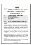
Fletcher
Product
Newsletter
J. H. Fletcher & Co.
www.jhfletcher.com
Inside
Page 2
Hydraulic
Pressure
Adjustments
Continued
Page 3
Pre Cleaner
Skirts
Vacuum
Page 4
Vacuum
Continued
Your E-Mail
Newsletter
on the Web
The Fletcher Product
Newsletter can be
downloaded from
www.jhfletcher.com.
From the home page,
click on Product
Newsletters. Select
the year and the issue
you would like to
download and click on
the link. You will need
Adobe Acrobat Reader
to view the newsletter.
Huntington, WV
2003 Issue 1
ROOF BOLTER HYDRAULIC
PRESSURE ADJUSTMENTS
A roof drill must be viewed as a collection of systems, all of which must be
operating properly in order for the machine
to operate with maximum safety and efficiency. The hydraulic pressures are but just
a part of one of the systems - the hydraulic
system. Attempting to compensate for
other issues by increasing the hydraulic
pressure can be a dangerous approach.
Pressure settings, depending upon the
machine function to which they relate, are
intended to 1) maintain a safe working
hydraulic pressure for the operator, and 2)
protect machine components, drilling tools
and the mine roof from excessive forces.
Inappropriate or excessive pressure settings
can result in damage to the machine or
drilling tools, not to mention serious operator injury or even death.
One of the most common problems
associated with “pressure” is an understanding of what creates pressure in a
hydraulic system. Pressure is created by
the restriction of flow. There must be flow
available from the pump before pressure
can be created. The majority of Fletcher
roof drills use gear type pumps. These
pumps develop a fixed flow output regardless of pressure. As the pump wears, the
ability of the pump to develop rated flow at
high pressure is reduced. This results in a
reduction in power output to the hydraulic
motor or cylinder being operated. Although
the static pressure output of the system may
be high, the corresponding volume output
can be almost zero. Hence, if the pump is
worn, simply raising the pressure setting
will not actually increase the overall output
of the circuit. But it can create a circumstance where, for instance, the drill thrust
could exceed safe limits causing the steel to
bend or break. Also, if a new pump is
installed without reducing the relief valve
setting, the pump could be damaged.
There are three important things to consider
before making any pressure adjustment:
KNOW WHAT YOU ARE ADJUSTING
KNOW WHY YOU ARE MAKING THE
ADJUSTMENT
KNOW WHAT THE CORRECT PRESSURE SETTING SHOULD BE
Additionally, consider other factors that
could be affecting machine performance
before attempting any pressure adjustment.
Some of these factors would include the
following:
Page 2
J. H. Fletcher & Co.
A. PUMP CONDITION
As pointed out earlier, if the pump is worn the
actual power output to the circuit being operated
will be reduced. Although it may be possible to
increase the static pressure setting, this will not
result in any improvement in operation and can
result in serious safety hazards.
B. HYDRAULIC OIL LEVEL
If the hydraulic oil level is low this will result in
heating, which will reduce pump and component
efficiency. In extreme cases cavitation will occur,
causing pump and component damage. Cavitation
will result in foaming of the hydraulic oil.
C. CONDITION OF HYDRAULIC OIL
Contaminated hydraulic oil will result in premature
hydraulic component failure. Always use the fill
pump system (manual or powered) when adding
hydraulic oil. Never pour hydraulic oil into the
machine through the breather cap opening. If the
hydraulic oil has been contaminated with water, the
oil will have a milky appearance.
D. FILTER CONDITION
Dirty pressure line filters will create additional
pressure loss in the system creating heat and reducing system effectiveness.
If the return line filters are dirty, this will create
excessive backpressure, again resulting in diminished system operation.
Clogging of the suction strainers (located in the
hydraulic tank) will starve the pumps and possibly
lead to cavitation.
E. MECHANICAL SYSTEM - BINDING,
ALIGNMENT AND LUBRICATION
If the system being operated, for instance the drill
feed or rotation, is not properly lubricated, maintained or adjusted, a considerable amount of the
power available to the system can be expended in
simply overcoming these problems resulting in
overall reduction in drilling ability. Drill head
alignment is particularly important on arm feed
style machines.
F. DUST COLLECTION SYSTEM
OPERATION
2003 Issue 1
The most important thing to remember when
troubleshooting or adjusting the drilling system is
that the hole cannot be drilled any faster than the
dust can be removed from the hole. Drilling rate
(speed) is directly related to the efficiency of the
dust suppression system. Always check the dust
suppression system for proper operation before
making any drilling system hydraulic adjustments.
Clogged hoses, leaks and dirty dust filters, worn
blowers or vacuum relief valves, will seriously
affect dust suppression system operation.
G. CONDITION OF DRILLING TOOLS DRILL STEELS AND BITS
As with the dust suppression system, the condition
of the drill steels and bits can seriously affect
drilling efficiency. Make sure bits are sharp, properly ground (if re-used) and drill steels are not bent,
cracked or broken. Also, try to minimize the use of
multiple drill steels.
Proper pressure settings are essential for safety.
Some of the hazards associated with incorrect
pressure settings include the following:
A. Drilling System:
Bending or breaking of drill steels can endanger the
operator resulting in serious injury or death.
B. Stabilizing Foot:
Setting the stabilizing foot with excessive pressure
can create a situation where the driller canopy can
strike the operator when the foot is retracted. This
has been discussed in Fletcher Information Bulletin
67, which is available on line at
www.jhfletcher.com or by contacting our Risk
Management Department at (304) 525-7811.
C. ATRS System:
If the ATRS pressure is set too low, the accumulator
will not be sufficiently charged during setting to
provide oil pressure for maintaining roof contact. If
the pressure is set too high, the system can exert
excessive pressure against the roof causing a possible dislodgment of roof material.
Page 3
J. H. Fletcher & Co.
Information concerning pressure settings and
machine maintenance and adjustment can be found
in the Service Manual. Keep in mind if you are
having problems identifying a circuit, the machine
hydraulics may have been modified or non-OEM
replacement components may have been used,
2003 Issue 1
which could affect how the machine operates and
expose your operator to a potentially unsafe piece of
equipment.
Additional information can be obtained by contacting our Risk Management Department.
PRECLEANER SKIRTS
Pre-cleaners have become a popular option
on Fletcher roof bolters. They minimize the
frequency of servicing the dust box, thereby
making the overall system more efficient. In
order to keep the pre-cleaners from being
damaged, they are mounted relatively high on
the machine. Depending on conditions, the
dust falling from the pre-cleaner could make a
cloud and be re-introduced into the mine air. In
order to help minimize this situation, precleaner skirts have been developed.
The skirt fits all Fletcher precleaner designs. The kit can be ordered in a 14” length
(part number: 56363 & 56221 or a 28” length
(part number: 56364 & 56221).
To attach the kit to the pre-cleaner the
operator should install the kit so that the
rubber skirt is not dragging on the ground,
this could suck water or dirt into the dust
system. We encourage you to look at this as
another way to control your operator’s exposure to dust. Even if you have a machine
mounted higher than 28”, the rubber can be
cut to length upon special request. To order,
call your Fletcher authorized parts distributor
or J.H. Fletcher & Co.
Skirt
Have you checked your vacuum lately?
The dust collection system used by J.H.
Fletcher & Co. has passed a MSHA performance
test. The MSHA approval incorporates all the
individual dust components into a certified
system. The vacuum setting used for testing is
based on blower performance (check your parts
manual for your specific blower). This vacuum
setting is stamped on the dust approval tag that is
usually located in the tram deck. This is the
minimum vacuum that can be used with the dust
approval. If the blower wears to the point that it
cannot maintain this pressure, it must be replaced.
You are required to use only genuine Fletcher
parts to maintain your dust collection system.
The importance of proper vacuum settings:
1. Less respirable dust: cuttings are properly
removed from the hole during the drilling
cycle creating a safer work environment.
Continued on page 4
J. H. Fletcher & Co.
Page 4
2003 Issue 1
Continued from page 3
2. Increased production: removing dust more
effectively increases drill penetration rate,
resulting in fewer bit changes and faster
cycle times.
3.
PN# 132121
Vacuum Pressure Gauge
Your E-Mail
J.H. Fletcher & Co. appreciates you sending us E-mail
and answering our web site survey. However, if you
are sending in E-Mail requests, we ask that you provide
us the following information: NAME , A FULL ADDRESS, PHONE NUMBER, AND YOUR E-MAIL ADDRESS.
PLEASE ADDRESS YOUR E-MAIL TO:
[email protected]
The information contained in this newsletter has
been obtained from sources believed to be reliable,
and the editors have exercised reasonable care to
assure its accuracy. However, J. H. Fletcher & Co.
does not guarantee that contents of this publication
are correct and statements attributed to other
sources do not necessarily reflect the opinion or
position of J. H. Fletcher & Co.
Published by J. H. Fletcher & Co.
Box 2187
Huntington, WV 25722-2187
c 2002
J. H. Fletcher & Co.
Box 2187
Huntington, WV 25722-2187
(304) 525-7811
Longer bit life: The bit stays cooler thus
increasing drilled footage and lowering bit
usage.
*Note: Check your complete dust collection system
at recommended intervals, as outlined in the
Fletcher maintenance manual, to keep your system
operating at an effective level of operation. Also
empty dust collection boxes at proper intervals to
keep them from getting overfilled.
To assist in checking the vacuum, Fletcher offers
a vacuum gauge (left) that is placed in the drill
chuck. the part number for the gauge is 132121.
Currently we are only sending the Fletcher Newsletter to a select
readership. If you know of someone in your company who wishes to be
placed on our mailing, please let us know. Below is a form for a free
subscription to the newsletter. Just fill out the form and return it to J. H.
Fletcher & Co., Risk Management, Box 2187, Huntington WV 25722-2187.
FREE SUBSCRIPTION FORM
Name_________________________ Job Title_________________
Company_____________________ Address__________________
City _______________________ State _____ Zip _____________
Phone ______________________